


MTDC 2 Door Access Control Interlock
The MTDC is a 2 door access control Interlock (man trap) board designed to be used with two
standalone access control readers or two networked access control readers. The MTDC
accepts door contact inputs and lock release inputs from 2 access control readers and controls
the lock release functions and traffic LED states according to the door states and the board’s
interlock logic.
Power Input (+12/24v-)
The MTDC accepts 12-24Vdc at 2 amps maximum. The input power is also routed to the lock control outputs. The
lock control outputs are auto-reset fused in the event a lock fails-shorted. See figure 1.
Door Override Input (+OVR-)
The MTDC OVR input accepts a 5-24vdc input Voltage or a dry relay contact input. The factory default is for a
Voltage input. See Figure 2 for jumper settings to set the board to accept a dry contact input. This input overrides
all interlock functions and opens both doors immediately. If traffic lights are connected to the MTDC, the red and
green LEDs will flash back and forth at ½ Hz. Once the override is removed the system resumes normal
operation. See figure 1.
Traffic Light Status Outputs (5V RD GN)
The MTDC allows the connection of up to 4 TLP-SS traffic light indicators to prompt persons using the interlock
system for “GO” and “STOP” situations. Below is a table of the various LED indications. See figure 1.
Green LED Red LED Condition
On solid Off Both doors secured, ready for a card read.
Off On Solid One or both doors are open, both must be closed to clear
Off Flashing Interlock timer is activated. User must wait for Green LED
Flashing Flashing Door override input is activated and both doors unlocked.
Note- After a valid card read, the green LED will stay lit until the door is opened.
Interlock Timer Output Relay (NC C NO)
This output changes state when the interlock timer is activated and the contacts are rated for 2 Amps. If the
interlock timer delay control is set to 0, this output changes state for 1 second. See figure 1.
Interlock Timer Delay (Delay)
This control allows for a delay between when the first door opens and when the second door is permitted to be
opened. During the adjustable delay of 0-60 seconds, The NC C NO output will change state. This output can be
used to trigger decontamination fans or other equipment. If the delay time is set to 0, the delay timer does not
function. During the interlock time interval, the red LED output will flash at a rate of 1/2Hz. See figure 1.
Door Contact Input (IN)
A NC (normally closed) door contact must be connected to these in puts for both doors in order for the MTDC to
function. See figure 1.
Door Contact Output (OUT)
This is a normally closed output that follows the state of the door contact input (IN). It is provided to report door
status to the connected access control reader to indicate forced door, door propped or auto-lock on door opened
conditions. See figure 1.
Door Unlock Input (-LC+)
The MTDC LC input accepts a 5-24vdc input Voltage or a dry relay contact input. The factory default is for a
Voltage input. See Figure 2 for jumper settings to set the board to accept a dry contact input. This input overrides
all interlock functions and opens both doors immediately. If traffic lights are connected to the MTDC, the red and
green LEDs will flash back and forth at ½ Hz. Once the override is removed the system resumes normal
operation. See figure 1.
Door Lock Output (COM NNV NV)
The locks are connected directly to these outputs. These outputs can supply up to 1 Amp at 12-24Vdc. NNV
stands for Normally No Voltage and NV stands for Normally Voltage. See figure 1.
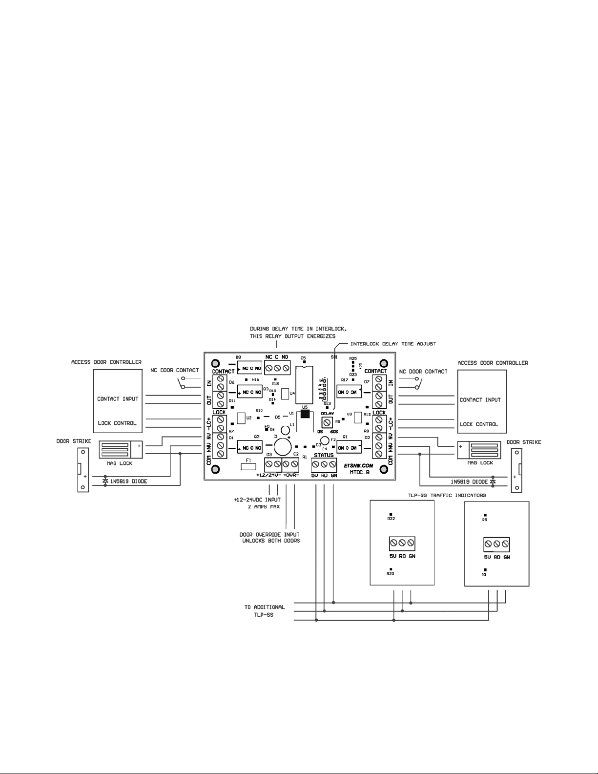
NOTE- Be sure to install transient protection diodes (such as type 1N5819) when using door strikes.
Maglocks can be directly connected to the board. See figure 1.
Figure 1.
 Loading...