

ETQ TG17M41 Owner's Manual
Owner’s Manual Model TG17M41

ETQ
EASTERN TOOLS & EQUIPMENT INC Tele: (888)908-6200 Web Site: easterntools.com
1
PREFACE
Thank you for purchasing products from EASTERNTOOLS & EQUIPMENT, INC. We
appreciate your business. The following manual is only a guide to assist you and is not a
complete or comprehensive manual of all aspects of maintaining and repairing your
generator. The equipment you have purchased is a complex piece of machinery. We
recommend that that you consult with a dealer if you have doubts or concerns as to your
experience or ability to properly maintain or repair your equipment. You will save time and
the inconvenience of having to go back to the store if you choose to write or call us
concerning missing parts, service questions, operating advice, and/or assembly questions.
Our gasoline generators have some of the following features:
.Lightweight construction
.Air cooled
.Four-stroke gasoline internal combustion engine
.Recoil starter
.Large fuel tank
.Automatic voltage stabilizer
.NFB circuit protector
.AC and DC outputs
.Low oil level sensor
The ETQ air-cooled gasoline generators are widely used when electrical power is scarce.
Our generators provide a portable mobile solution in supplying power for field operations
during project construction.
This manual will explain how to operate and service your generator set.
If you have any questions or suggestions about this manual, please contact your local
dealer or us directly. Consumers should notice that this manual might differ slightly
from the actual product as more improvements are made to our products. Some of
the pictures in this manual may differ slightly from the actual product as well.
Eastern Tools and Equipment, Inc. reserves the right to make changes at any time
without notice and without incurring any obligation.

ETQ
EASTERN TOOLS & EQUIPMENT INC Tele: (888)908-6200 Web Site: easterntools.com
2
TABLE OF CONTENTS
Page
TECHNICAL SPECIFICATIONS AND DATA 3
EQUIPMENT DESCRIPTION & KNOWING YOUR GENERATOR 4
SAFETY PRECAUTIONS 5
Danger
5
Electric shock and short circuit
5
Prevention from accidental burns
5
Refueling precautions
5
Engine safety precautions
6
Generator safety
6
PREPARATION BEFORE OPERATION 6
Engine oil
6
Gasoline
7
Air cleaner
7
GROUNDING THE GENERATOR 8
OPERATING THE GENERATOR 8
Starting the engine
8
Connecting electrical loads and electrical capacity
9
Stopping the engine
10
RECEPTACLES 11
MAINTENANCE 12
Cleaning the generator
13
Spark Plug
13
Storage
14
TROUBLESHOOTING 15
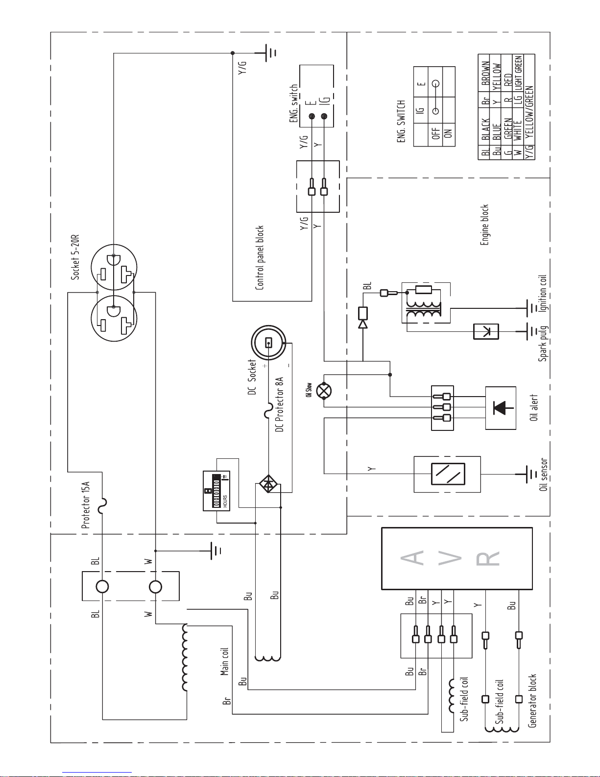
Wiring Diagram 16
PARTS LISTING 17
EXPLODED GENERATOR VIEW
17
CRANKCASE
20
PUSH ROD & VALVE ROCKER
21
CYLINDER HEAD & CYLINDER HEAD COVER ASSEMBLY
22
CRANKCASE COVER ASSEMBLY
23
CRANKSHAFT, PISTON & TIE-ROD
24
CARBURETOR ASSEMBLY & AIR CLEANER ASSEMBLY
25
FLYWHEEL & RECOIL STARTER
26
IGNITION COIL
27
REGULATING CONTROL SYSTEM
27
LIMITED WARRANTY 28
PRODUCT REGISTRATION 31

ETQ
EASTERN TOOLS & EQUIPMENT INC Tele: (888)908-6200 Web Site: easterntools.com
3
TECHNICAL SPECIFICATIONS AND DATA
TG17M41
Engine Type 4-stroke, Air-cooled, OHV
Displacement
119 cc
12.14 cu in
Bore × Stroke
60×42 mm
2.36×1.65 in
Engine Rated Power
2.94 KVA @ 3600 r/min
4 Hp @ 3600 r/min
Fuel Unleaded
Fuel Tank Capacity
13 L
3.43 Gal
Operation Hours 11Hrs @ 50% load
Engine Oil SAE 10W-30 or equivalent motor oil
Engine Oil Capacity
0.6L (20.3 Ounces)
1.Need to add oil to engine when “oil warning light “ is on.
2.Engine may stop and will damage if the oil is too low.
Engine Start Pattern Manual start
Generator Type Synchronous generator
Phase Single
Power Factor Cos θ = 1.0
AC Output Voltage 120V
AC Output Frequency 60Hz
AC Output Max Power 2250 ± 10% Watts
AC Output Rated Power 1750 ± 5% Watts
DC Output Voltage 12V
Noise Level 65 dB @ 7m
Product Weight
35 kg
77.2 lbs
Product Dimensions
51.6x43.0x43.5 cm
20.31x16.93x17.13 in
ETQ
EASTERN TOOLS & EQUIPMENT INC Tele: (888)908-6200 Web Site: easterntools.com
4
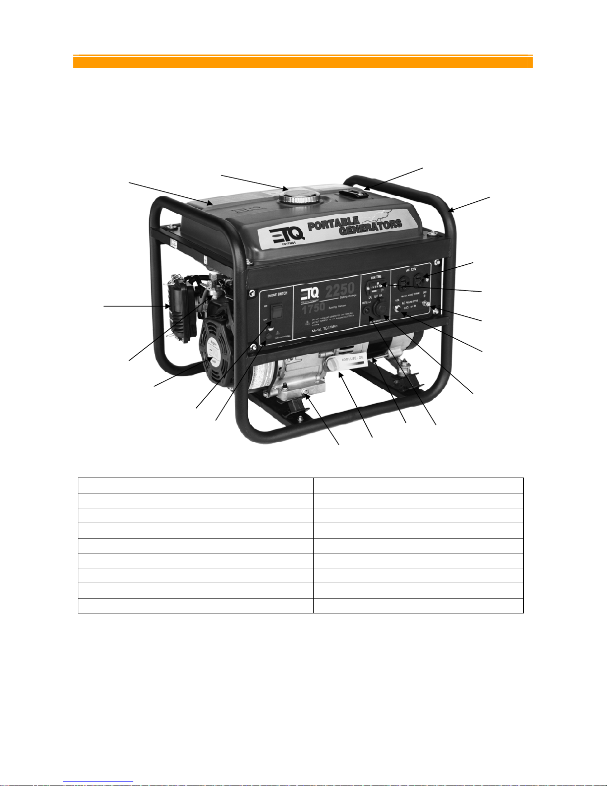
EQUIPMENT DESCRIPTION & KNOWING YOUR GENERATOR
Please read this manual and follow the procedures covered in this manual. Become familiar with the
generators functions, applications, and limitations.
Below is a diagram of the locations of the various controls and functions of the generator
(1) ENGINE SWITCH (10) HOUR METER
(2) OIL INDICATOR LIGHT ASSY (11) 120V Duplex Receptacle 5-20R
(3) OIL DRAIN PLUG (12) FRAME COMP
(4) OIL FILLER CAP (13) FUEL GAUGE
(5)ALTERNATOR (14) FUEL TANK CAP
(6) DC CIRCUIT BREAKER 8A (15) TANK COMP,FUEL
(7) DC RECEPTACLE (16) AIR CLEANER
(8) AC CIRCUIT BREAKER 14.5A (17) COCK ASSY.FUEL
(9) GROUND TERMINAL (18)RECOIL STARTER
WARNING: DO NOT exceed the generator’s wattage/amperage capacity. Our products are
continuously being changed and improved. Every effort has been made to ensure that information in the
manual is accurate and up to date. However, we reserve the right to change, alter or otherwise improve
the product and this manual at any time without prior notice.
(3)
(1)
(11)
(4)
(3)
(5)
(6)
(18)
(7)
(8)
(9)
(10)
(12)
(13) (14) (14)
(15)
(16)
(17)
(18)
ETQ
EASTERN TOOLS & EQUIPMENT INC Tele: (888)908-6200 Web Site: easterntools.com
5
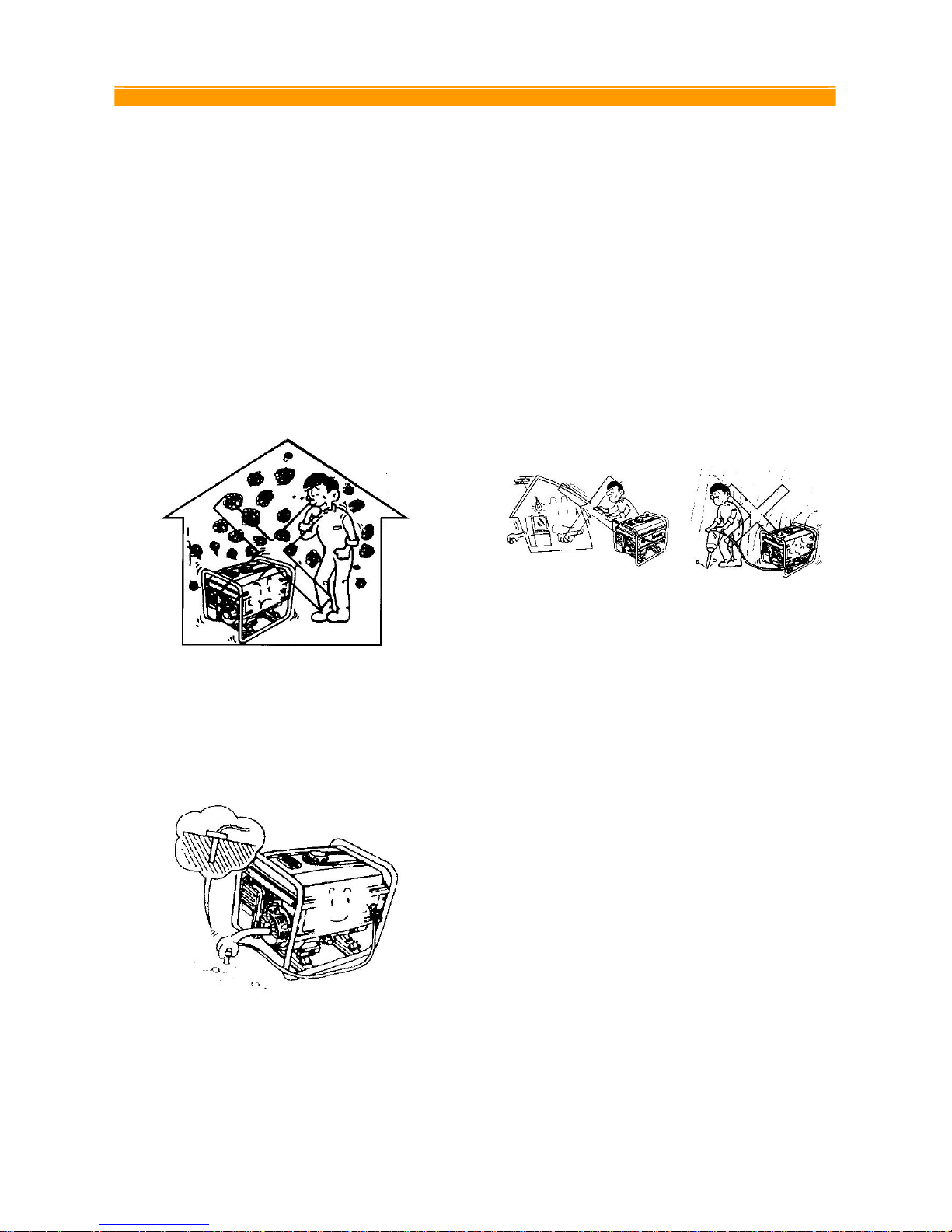
SAFETY PRECAUTIONS
In order to ensure safety for the consumer,
please carefully follow instructions on being
careful with the generators.
Operate the generator ONLY outdoors. Never
run the generator indoors as the engine gives
off poisonous carbon monoxide, an odorless
and colorless gas. Inhaling carbon monoxide
will cause nausea, fainting or death. Also, keep
the generator at least 3 feet away from
flammable matter for adequate ventilation.
DANGER
Always properly ground the generator. Failing to
do so can result in electrocution, particularly if
the generator is equipped with a wheel kit.
ELECTRIC SHOCK AND SHORT CIRCUIT
Be sure to notify the utility company when using
the generator for backup power. Use approved
transfer equipment to isolate the generator from
electric utility. In highly conductive area such as
metal decking or steel work, use a ground circuit
fault interrupter. Never touch the generator if the
generator is wet. Also, never touch the
generator if your hand is wet. Never operate
your generator if the weather conditions call for
any type of precipitation such as rain, snow, or
fog.
PREVENTION FROM ACCIDENTAL BURNS
Never touch the muffler and its cover when the
engine is running. Never touch the muffler and
cover after the engine has been used, as the
muffler remains hot for a good period of time.
REFUELING PRECAUTIONS
Gasoline and its vapors are extremely
flammable. Do not smoke near gasoline and
keep gasoline away from generator while the
generator is running. When adding fuel, turn the
generator off and let it cool at least 2 minutes
before removing the gas cap. Loosen gas cap
slowly to relieve the pressure in the tank.
Fill fuel tank outdoors and never overfill the
tank.
ETQ
EASTERN TOOLS & EQUIPMENT INC Tele: (888)908-6200 Web Site: easterntools.com
6
When storing gasoline or equipment with fuel in
tank.
Store away from appliances or equipment that
have a pilot light or other ignition sources
because it can ignite gasoline vapors.
ENGINE SAFETY PRECAUTIONS
Do not touch hot surfaces. Allow equipment to
fully cool down before touching.
After the generator has been run, the engine
produces heat. The temperature of the muffler
and nearby areas can reach or exceed 1600 F.
Severe burns will occur on contact with skin. Do
not modify the generator in any way. The
generator supplies the rated voltage and rated
frequency at its governed speed.
GENERATOR SAFETY
Never overload your generator as this can
damage your generator or the electrical devices
connected to it
Do not start generator with electrical devices
connected to it. Start the generator first and after
the speed of the generator stabilizes, electrical
loads can be applied to it.
When connecting electrical loads, make sure
the devices are "OFF" first before connecting
them. Keep the same concept when
disconnecting electrical devices; make sure all
devices are in the "OFF" position before
disconnecting.
Operate the generator on level surfaces only.
Inclined surfaces reduce the effective lubrication
of the engine.
Do not expose the generator to excessive
moisture, dust, dirt, or corrosive vapors.
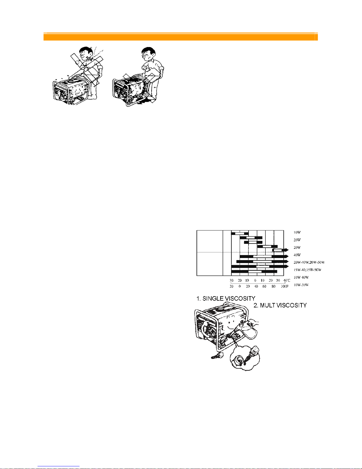
PREPARATION BEFORE
OPERATION
Before starting the generator, verify the
following conditions.
ENGINE OIL
• Fill the engine with SAE 10W-30 engine oil
for generator use or follow the table below.
• Make sure the generator is on a level
surface and make sure the oil dipstick is on
tight.
ETQ
EASTERN TOOLS & EQUIPMENT INC Tele: (888)908-6200 Web Site: easterntools.com
7
GASOLINE
• Add unleaded gasoline and never fill the fuel
tank indoors. Also, be sure to install the fuel
tank cap on tight after filling.
• DO NOT overfill the fuel tank. Always allow
room for fuel expansion. Never fill the fuel
tank when the engine is running or hot.
Allow the unit to cool for two minutes before
refueling. DO NOT use light a cigarette or
smoke when filling the fuel tank.
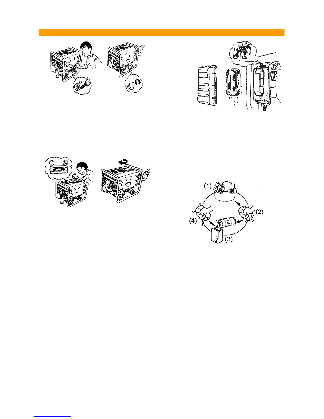
AIR CLEANER
• Unsnap the air cleaner cover springs, and
remove the air cleaner cover.
• Check the air cleaner element to be sure
they are clean and in good condition.
• If the air filter is dirty, remove and clean the
element.
o Wash in solvent
o Squeeze
o Soak oil
o Squeeze dry
• Reinstall the air cleaner element and secure
the cover by setting the cover spring.
ETQ
EASTERN TOOLS & EQUIPMENT INC Tele: (888)908-6200 Web Site: easterntools.com
8
GROUNDING THE GENERATOR
The National Electric Code requires that the
frame of generator and the external electrically
conductive parts of the generator be connected
to an approved earth ground. Local codes may
differ and require other grounding specifications.
For this purpose, please use the ground wire
that attaches from the frame to the generator
unit.
Using a No. 12 AWG (American Wire Gauge)
stranded copper wire to the frame and to an
earth-driven copper or brass grounding rod
provides sufficient safety against shock.
However, local codes may differ. Contact a local
electrician to find out specifications for
grounding your generator.
Note: Grounding your generator is highly
recommended. It helps prevent electrical shock
if a ground fault condition exists in the generator
or in faulty connected electrical devices. Also,
because the generator is rotating at high speeds,
static electricity tends to buildup within the unit.
Grounding helps dissipate the static electricity
buildup often buildup in underground devices.
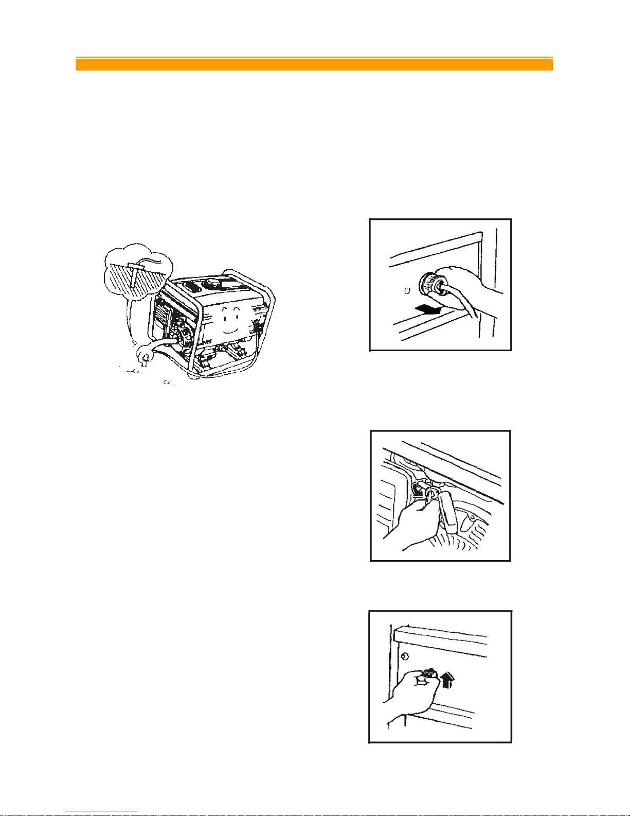
OPERATING THE GENERATOR
STARTING THE ENGINE
Before starting the engine, verify that the engine
oil is full, gasoline is full, and air Filter is in place.
Also, disconnect any load from the AC
receptacle (Figure 1) .
Figure 1. Disconnecting electrical devices
• Turn the fuel valve to the "On" position
(Figure 2).
Figure 2. Fuel Valve
Figure 3. Engine switch on position
ETQ
EASTERN TOOLS & EQUIPMENT INC Tele: (888)908-6200 Web Site: easterntools.com
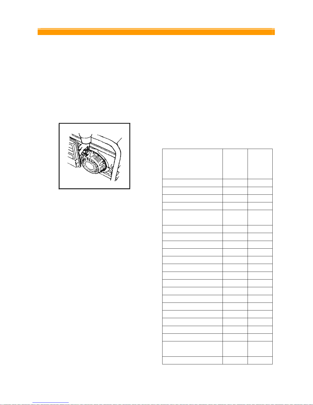
9
• Pull the recoil starter grip lightly until
resistance is felt, then pull hard(Figure 4).
• Warning: Do not allow the starter grip to
snap back against the engine. Return it
gently.
• When start the generator, please push the
choke rod to the “close” position. If can not
start with the correct step, please adjust the
position of the choke rod.
Figure 4. Recoil starting rope
• Push the choke rod to the "OPEN" position
a short distance at a time over several
seconds as the engine warms up.
CONNECTING ELECTRICAL LOADS AND
ELECTRICAL CAPACITY
After starting the generator, let the engine warm
up after connecting electrical loads to it. Do not
have any electrical loads connected before
starting the generator.
Make sure all electrical devices are 60 Hz
devices.
Do not connect 50 Hz devices to the generator.
Do not connect 3-phase loads to the generator.
Do not overload the generator.
Before beginning your work, you must verify that
the rated (running) and surge (starting) watts for
the items you will power at the same time are
within the generators operating capacity. Please
refer to the following Table 1 for wattage /
amperage ratings. Also, to prolong the life of
your generator, prolong the life of your generator,
sequentially add loads and permit the generator
to stabilize before adding another load. Never
exceed the capacity of the generator.
Estimate how many surge (starting) watts you
will need. Surge wattage is the short burst of
power needed to start electric motor-driven tools
or appliances such as a circular saw or
refrigerator.
Table 1. Wattage reference chart
Tool or Appliance
Rated
(Running)
Watts
Additional
Surge
(Starting)
Watts
Essentials
Light Bulb – 75 watt 75 Freezer 500 500
Sump Pump 800 1200
Refrigerator / Freezer – 18
Cu. Ft.
800 1600
1/3 HP Water Well Pump 1000 2000
Heating/Cooling
Air condition – 10000 BTU 1200 1800
Window Fan 300 600
½ HP Furnace Fan Blower 800 1300
Kitchen
1000 Watt Microwave Oven 1000 -
Coffee Maker 1500 Single element electric stove 1500 Hot plate 2500 -
Family Room
DVD / CD Player 100 VCR 100 -
Stereo Receiver 450 27 “ Color Television 500 Personal Computer w/17”
monitor
800 -
Other
ETQ
EASTERN TOOLS & EQUIPMENT INC Tele: (888)908-6200 Web Site: easterntools.com
10
Security system 180 -
AM / FM clock radio 300 ½ HP Garage door opener 480 520
40 Gallon electric water
heater
4000 -
DIY / Job Site
Halogen work light 1000 1/3 HP Airless sprayer 600 1200
Reciprocating Saw 960 960
½ HP Electric Drill 1000 1000
7 ¼ “ Circular saw 1500 1500
10” Miter saw 1800 1800
6” Table Planer 1800 1800
10” Table saw / Radial arm
saw
2000 2000
1 ½ HP air compressor 2500 2500
Note: wattages listed are only approximates. Check
your electrical device for actual wattage.
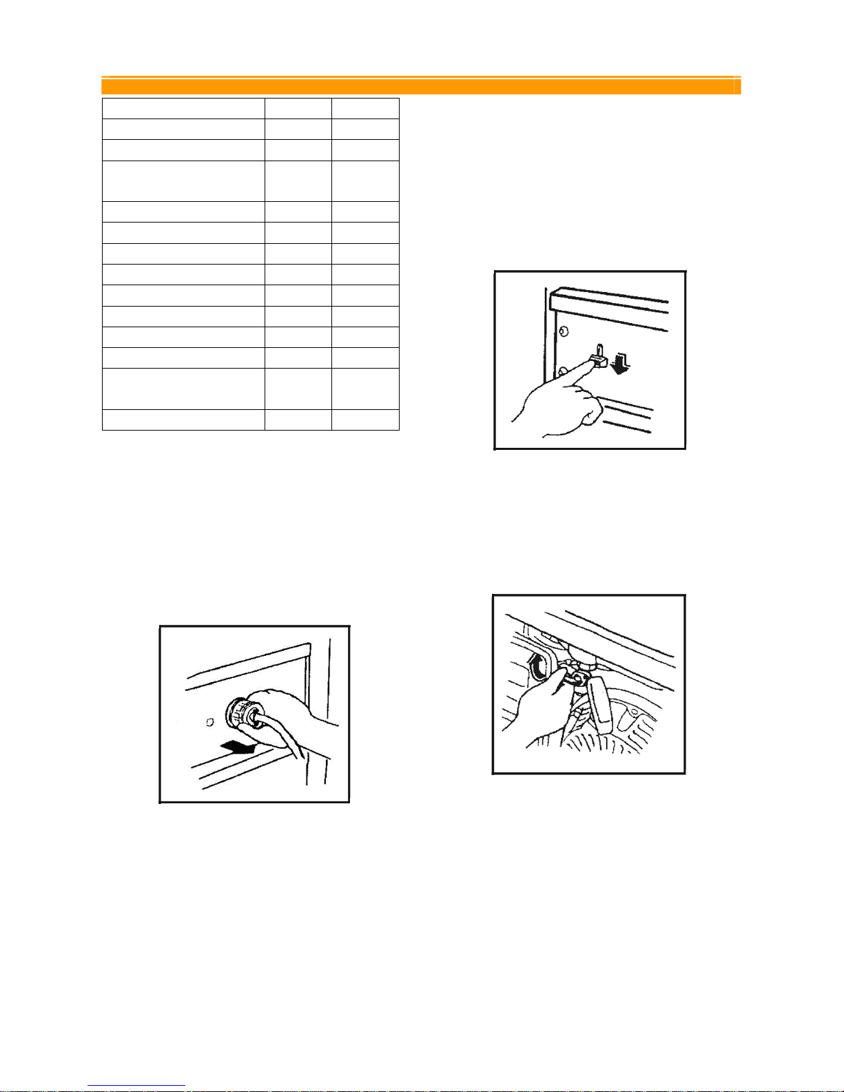
STOPPING THE ENGINE
• Unplug all the electrical loads from the
generator panel (Figure 1).
Figure 1.
• Let the engine run at no-load for several
minutes to stabilize the internal
temperatures of engine and generator.
• Turn the engine switch to the "OFF" position
(Figure 2).
Figure 2.
• Turn the fuel valve to the "OFF" position
(Figure 3).
Figure 3.
ETQ
EASTERN TOOLS & EQUIPMENT INC Tele: (888)908-6200 Web Site: easterntools.com
11
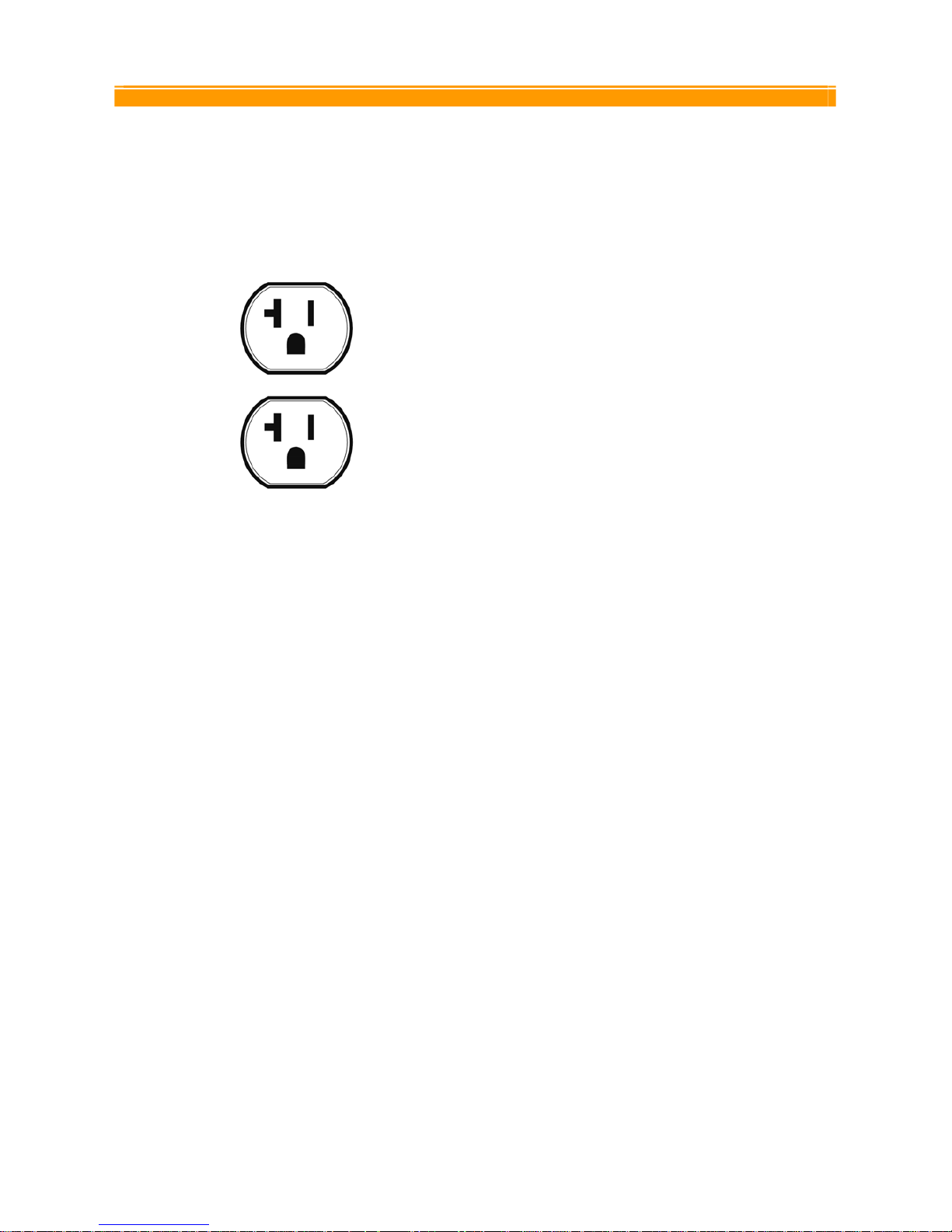
RECEPTACLES
This generator is equipped with the following
Receptacles
NEMA 5-20R: 125 Volt, 20 Amp Duplex
Receptacle
Note: Please be sure to use electrical cords that
support the amount of wattage being used.
The electrical cords should be able to handle 20
Amps of current at 125 Volts.
ETQ
EASTERN TOOLS & EQUIPMENT INC Tele: (888)908-6200 Web Site: easterntools.com
12
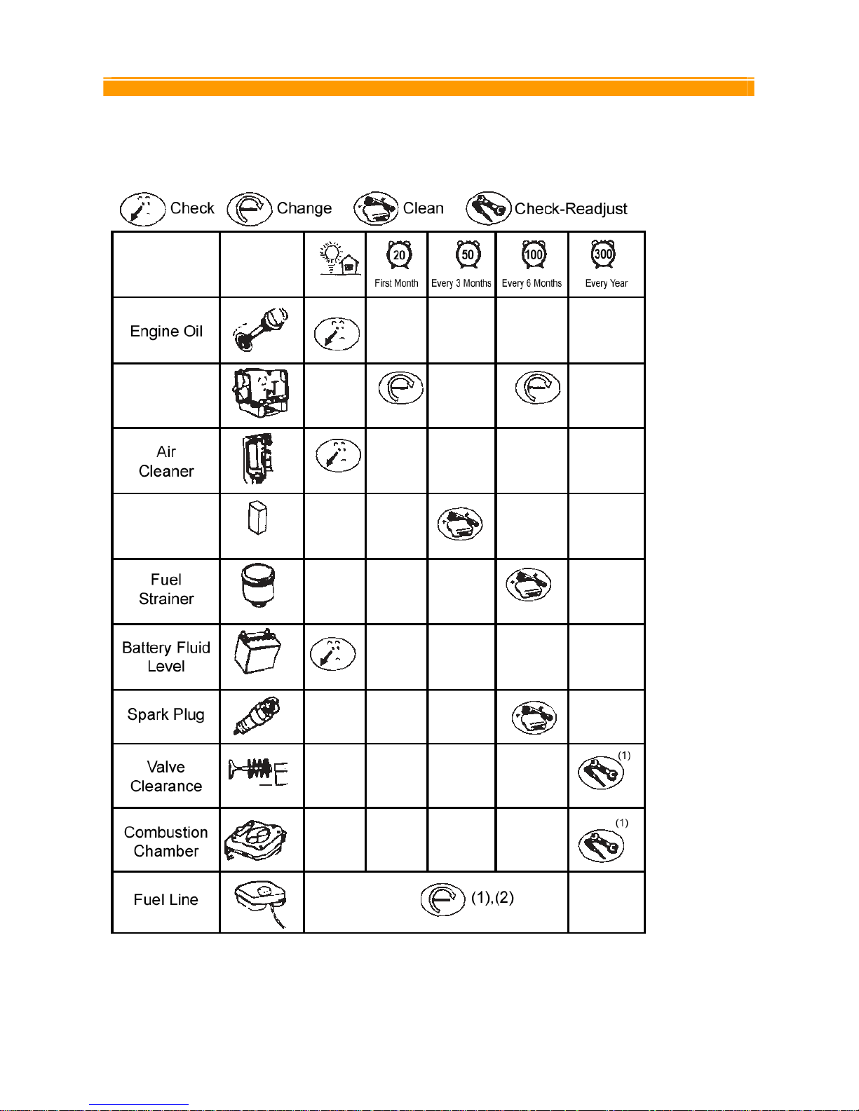
MAINTENANCE
Below is a routine maintenance schedule.
(1): These items should be serviced by a dealer.
(2): Every 3 years.
ETQ
EASTERN TOOLS & EQUIPMENT INC Tele: (888)908-6200 Web Site: easterntools.com
13
CLEANING THE GENERATOR
Generator maintenance consists of keeping the
unit clean and dry. Be sure to store the unit in a
clean and dry environment, where it will not be
exposed to excessive dust, dirt, moisture or any
corrosive vapors. Cooling slots should always
be clean and free from clogs.
Note: Do not use a garden hose to clean the
generator. Water can enter the fuel and intake
system and cause problems. In addition, if water
and dirt buildup on the generators internal
windings, the resistance of these windings will
decrease.
• To clean the generator, use a damp cloth to
wipe the exterior surfaces.
• Use a soft bristle brush to loosen caked on
dirt of oil.
• Use a vacuum cleaner to pick up loose dirt
and debris.
• Compressed air (not to exceed 25 psi) may
be used to blow away dirt.
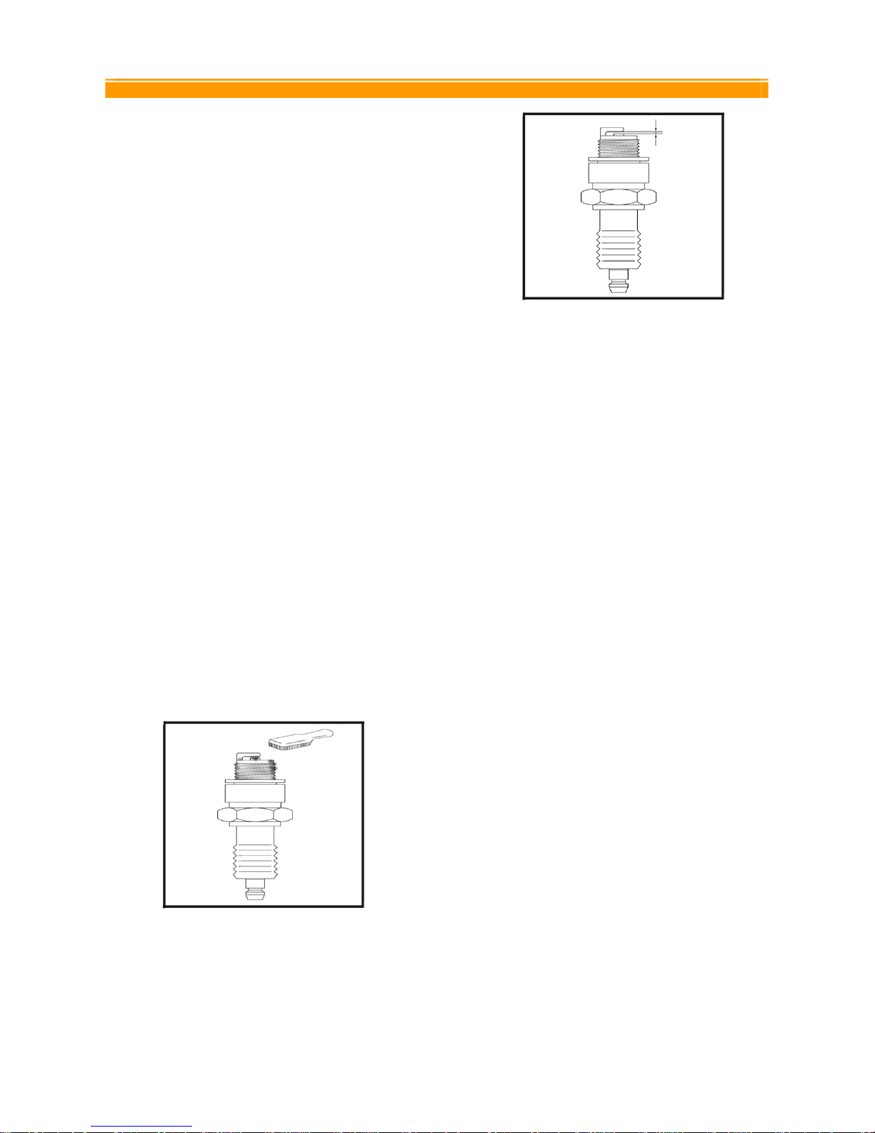
SPARK PLUG
• Remove the spark plug
• Remove the carbon deposits
• Check for discoloration. Standard is tan in
color.
• Check spark plug gap
Gap measurements
0.7~0.8 mm (.028~.031 inches)
NOTE: If spark plug needs to be replaced, use
NGK(or LG) Brand: BPR4ES or F6(R)TC
ETQ
EASTERN TOOLS & EQUIPMENT INC Tele: (888)908-6200 Web Site: easterntools.com
14
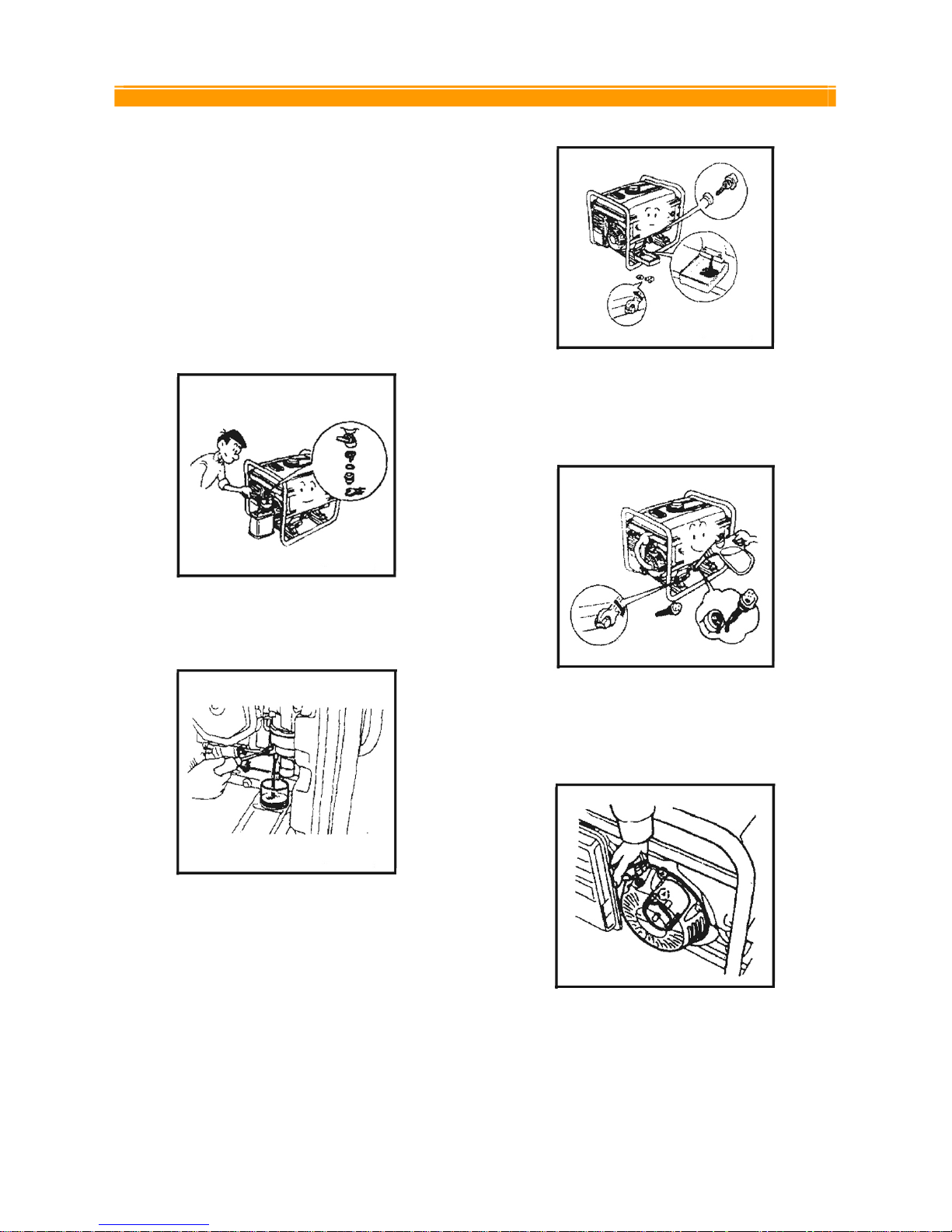
STORAGE
The generator should be started at least once
every week. If this cannot be done and you must
store the unit more than 30 days, please follow
the following guidelines.
Close the fuel valve: drain the fuel from the fuel
tank (Figure 1).
Figure 1.
• Drain the fuel from the carburetor (Figure 2).
Figure 2.
• Remove the oil filter cap and drain plug to
drain the oil (Figure 3).
Figure 3.
• Tighten the oil drain plug and fill the engine
with new oil to the filter neck (Figure 4).
Figure 4.
• Pull the starter grip carefully until resistance
is felt (Figure 5).
Figure 5.
• Store the generator in a clean area.

ETQ
EASTERN TOOLS & EQUIPMENT INC Tele: (888)908-6200 Web Site: easterntools.com
1
TROUBLESHOOTING
IMPORTANT: If trouble persists please call our customer help line at (888) 908-6200 M-F
8-5 Central Time.
Problem Cause Solution
Engine switch is set
to "off".
Set engine switch to "on" position.
Fuel valve is turned
to "closed".
Turn fuel valve to "open" position.
Choke is open. Close the choke
Engine is out of gas. Add gas.
Engine is filled with
contaminated or old
gas
Change the gas in the engine.
Spark plug is dirty. Clean spark plug.
Spark plug is broken. Replace spark plug.
Generator is not on
level surface.
Move generator to a level surface to prevent low oil shutdown
from triggering.
Engine will not
start
Oil is low Add or replace oil.
Circuit reset button is
off.
Wait for 2 minutes and push the circuit reset button to the "on"
position.
Bad connecting
wires/cables.
If you are using an extension cord, try a different one.
Engine runs but
there is no
electrical output
Bad electrical device
connected to
generator.
Try connecting a different device.
Generator is
overloaded
Try connecting fewer electrical loads to the generator.
There is a short in
one of the connected
devices.
Try disconnecting any faulty or short-circuited electrical loads.
Generator runs,
but does not
support all
electrical devices
connected to it.
Air cleaner is dirty. Clean or replace air cleaner.
ETQ
EASTERN TOOLS & EQUIPMENT INC Tele: (888)908-6200 Web Site: easterntools.com
3
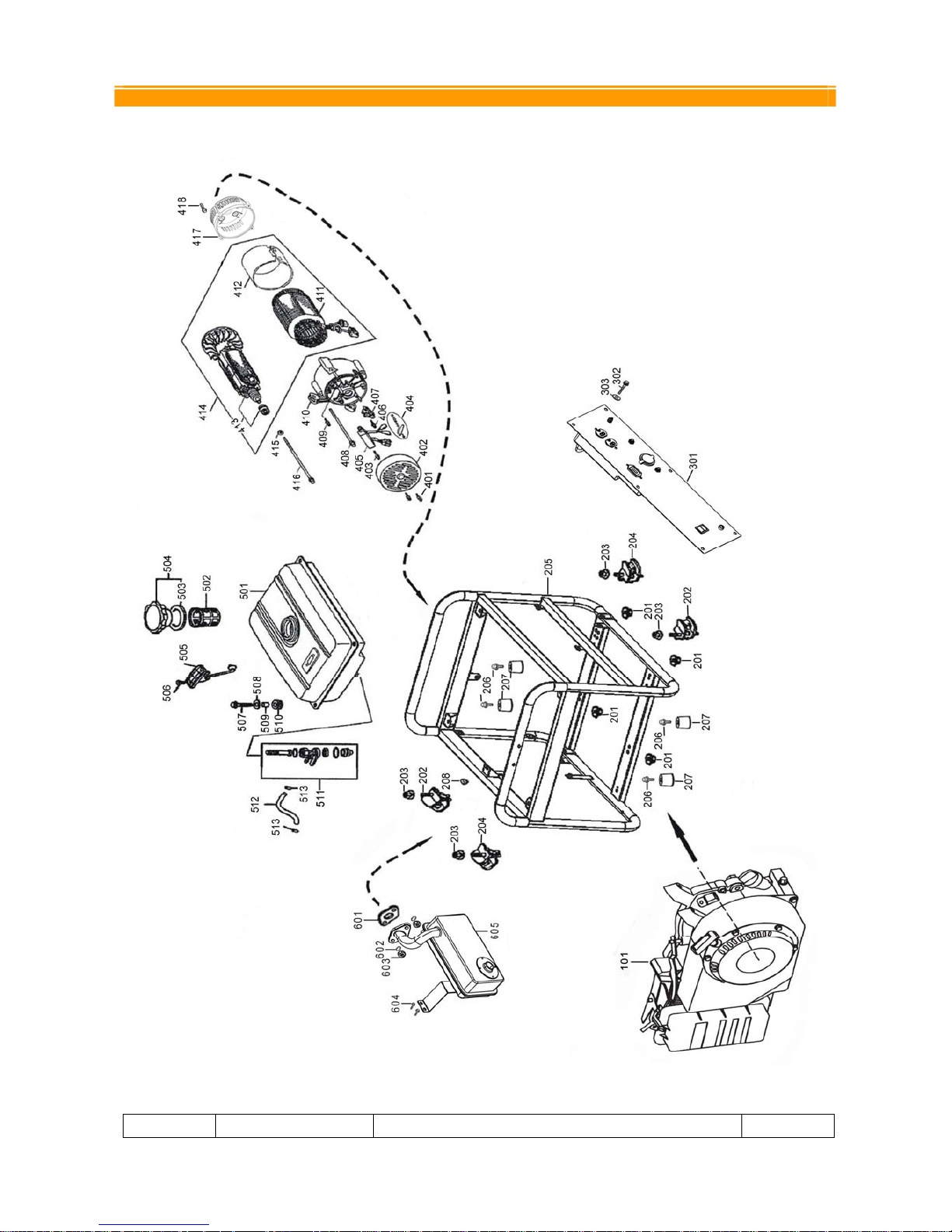
PART LISTINGS
EXPLODED GENERATOR VIEW
NUMBER PART NUMBER DESCRIPTION QTY

ETQ
EASTERN TOOLS & EQUIPMENT INC Tele: (888)908-6200 Web Site: easterntools.com
4
101 GASOLINE ENGINE 1
201 94050-08000-00 NUT FLANGE M8 4
202 77320-168-00 BOTTOM RUBBER A 2
203 94050-08000-00 NUT FLANGE M8 4
204 77330-168-00 BOTTOM RUBBER B 2
205 50310-A17-00 FRAME COMP 1
206 95701-06012-00 BOLT,FLANGE,6X12 4
207 60407-168-00 RUBBER PAD,FRAME(NUT) 4
301 33110-T17-00 CONTROL PANEL CASE 1
302 95701-06012-00 BOLT.FLANG M6×12 6
303 94101-06000-00 WASHER PAPER 6MM 6
401 95701-05012-00 BOLT,FLANGE 5×12 2
402 31203-168-00 BRACKET,RR.,MOTOR(BLACK) 1
403 95701-05016-00 BOLT,FLANGE 5×16 2
404 19620-168-00 CONNECTION FLAT 1
405 30300-168-00 VOLTAGE REGULATOR 1
406 95701-05016-00 BOLT,FLANGE 5×16 1
407 31160-168-00 BRUSH ASSY 1
408 95701-06105-00 BOLT FLANGE(STATOR) 6×10⁵ 4
409 95701-05012-00 BOLT,FLANGE 5×12 1
410 31170-168-00 GENERATOR STAY 1
411 31120-A17-00 STATOR COMP 1
412 31150-A17-00 STATOR COVER 1
413 31130-A17-00 ROTOR,COMP 1
414 31200-A17-00 MOTOR ASSY.,STARTING(3.25KW) 1
415 94102-08000-00 WASHER,PLAIN(ROTOR) 8MM 1
416 95701-08200-00 BOLT(ROTOR)8×200 1
417 11310-160-00 ADPT ENG MACH HONDA/HON OHV PLN 1
418 95701-08025-00 BOLT,FLANGE 8X25 4
501 17510-T17-00 TANK COMP,FUEL(BLUE) 1
502
15420-168-00 FUEL FILLER
1
503 17631-168-00 PACKING,FUEL FILLER CAP 1
504 17620-168-01 CAP COMP,FUEL FILLER 1
505 17640-168-00 FUEL SENSOR ASSY 1
506 93800-05010-00 SCREW, FLAT, 5×10 2
507 95701-06025-00 BOLT, FLANGE, 6×25 4
508 90486-06000-00
WASHER, TANK CUSHION 4
509 90324-168-00
FITTING BRUSH 6MM 4
510 17613-168-00
CUSHION,FUEL TAND 4
NUMBER PART NUMBER DESCRIPTION QTY

ETQ
EASTERN TOOLS & EQUIPMENT INC Tele: (888)908-6200 Web Site: easterntools.com
5
511 16950-168-00 COCK ASSY.FUEL 1
512 95001-168-00 TUBE,FUEL 4.5×115 1
513 95003-168-00 CLIP,TUBE (B8) 2
601 18381-170-00 GASKET,MUFFLER 1
602 94111-08000-00 WASHER,SPRING 8.5MM 2
603 94050-168-00 NUT 8MM 2
604 95701-06012-00 BOLT,FLANGE 6X12 2
605 18310-160-00 MUFFLER COMP 1
ETQ
EASTERN TOOLS & EQUIPMENT INC Tele: (888)908-6200 Web Site: easterntools.com
6
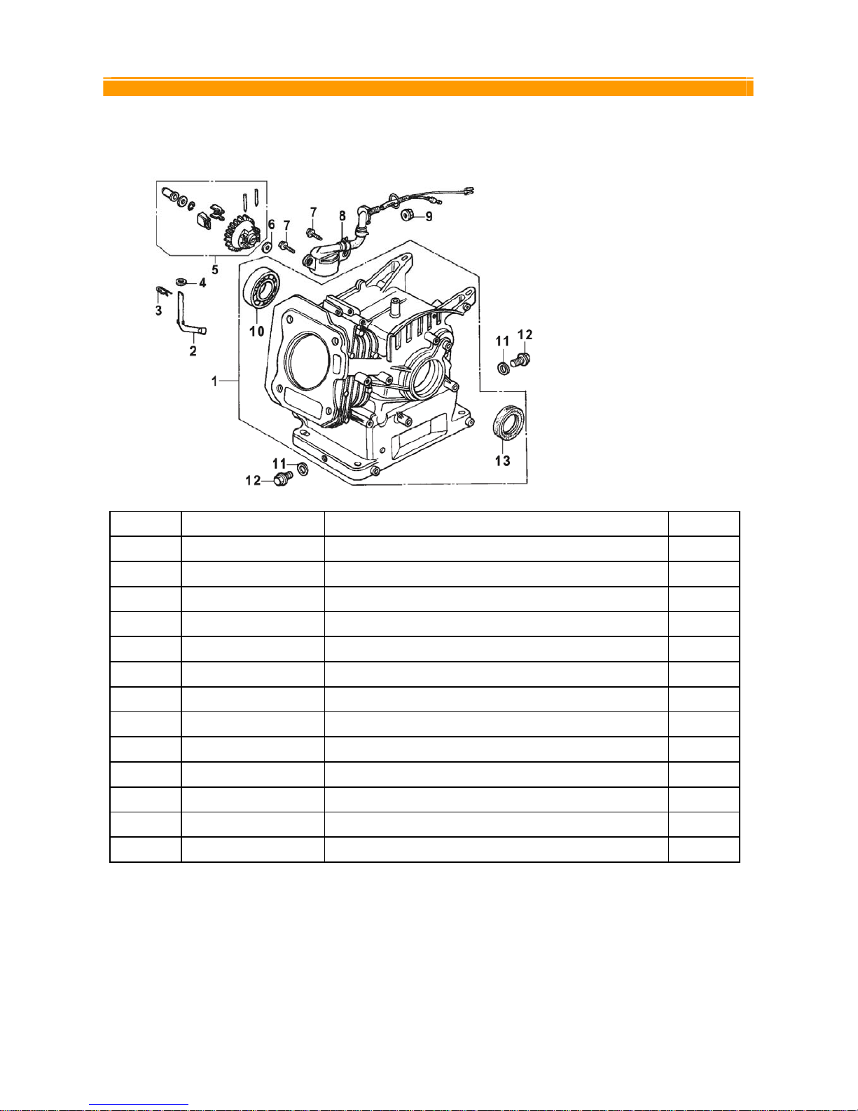
CRANKCASE
NUMBER PART NUMBER DESCRIPTION QTY
1 12000-160-00 CRANKCASE 1
2 16541-160-00 SHAFT,GOVERNOR ARM 1
3 94251-08000-00 PIN,LOCK,8MM 1
4 94101-168-00 WASHER,PLAIN 1
5 16506-168-00 GOVERNOR ASSY 1
6 94101-168-00 WASHER,PLAIN 1
7 95701-06016-00 BOLT,FLANGE,6X16 2
8 15510-168-00 SWITCH ASSY,OIL LEVEL 1
9 94050-10000 -00 NUT, FLANGE, 10MM 1
10 96100-168-00 BEARING BALL RADIAL 6205 1
11 90601-10200-00 WASHER,PLUG DRAIN 10.2MM 2
12 95701-10015-00 BOLT,PLUG,DRAIN 10×15 2
13 91201-160-00 OIL SEAL 1
 Loading...