

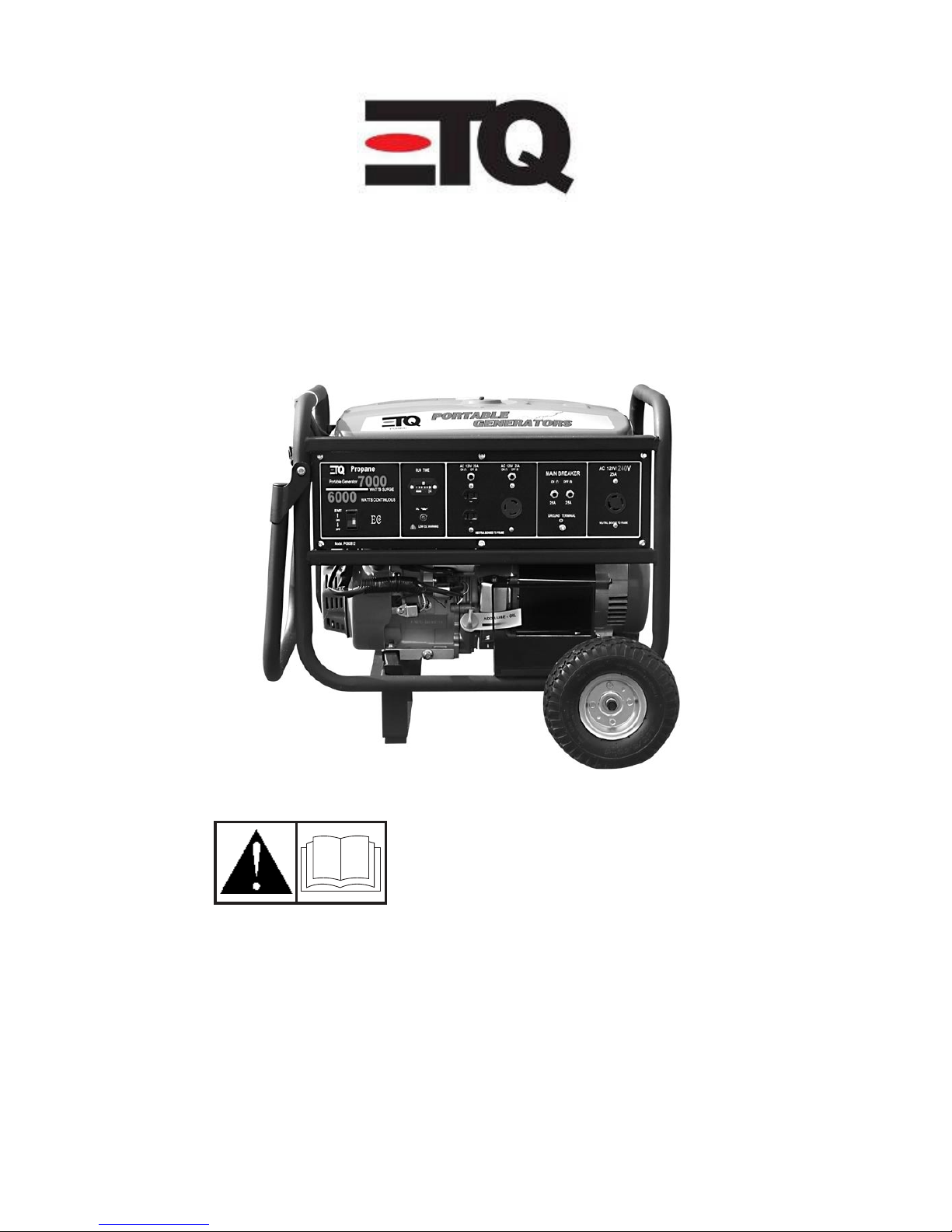
ETQ Liquid Propane Operation Manual
1
Eastern Tools & Equipment, Inc
Liquid Propane Portable Generator
Operation Manual
7000 Surge Watts
6000 Continuous Watts
Customer Service (888)-696-2345
www.easterntools.com
Eastern Tools & Equipment. Inc
Ontario, CA U.S.A

2
Thank you for purchasing products from EASTERNTOOLS & EQUIPMENT, INC. We appreciate your
business. The following manual is only a guide to assist you and is not a complete or
comprehensive manual of all aspects of maintaining and repairing your generator. The equipment
you have purchased is a complex piece of machinery. We recommend that that you consult with a
dealer if you have doubts or concerns as to your experience or ability to properly maintain or repair
your equipment. You will save time and the inconvenience of having to go back to the store if you
choose to write or call us concerning missing parts, service questions, operating advice, and/or
assembly questions.
This manual will explain how to operate and service your generator set.
Please fill out the inform ation below. This will help you save time if you ever need to provide the
following information for a warranty repair.
GENERATOR
Model Number: _________________________________________
Serial Number: ____________ ______________________________
E N G I N E
Model Number: _________________________________________
DATE PURCHASED: ____________ ____Day _______________Month ________________YEAR
TABLE OF CONTENTS
Safety warning 3
Sp ecification s/O il 4
Control and Features 5
Reductor assembly 6
Handle and Wheel Kit 7
Starting the unit 8
Connecting loads 8
Stopping the unit 8
Maintenance 9
Trouble shooting 10
Wi re Dia gram 11
Parts Diagram 12
Warranty 13
3
Safety Warning
Please read this manual to understand how to
use your unit as well as understanding the risk
the come with the u nit.
NOTICE exceeding your generator wattage/
amperage coverage capacity can damage your
unit as well as any devices attached to your unit.
Consumers should notice that this manual might
differ slightly from the actual product as more
improvements are made to our products. Some
of the pictures in this manual may differ slightly
from the actual product as well. Eastern Tools
and Equipment, Inc. reserves the right to make
changes at any time without notice and with out
incurring any oblig ation
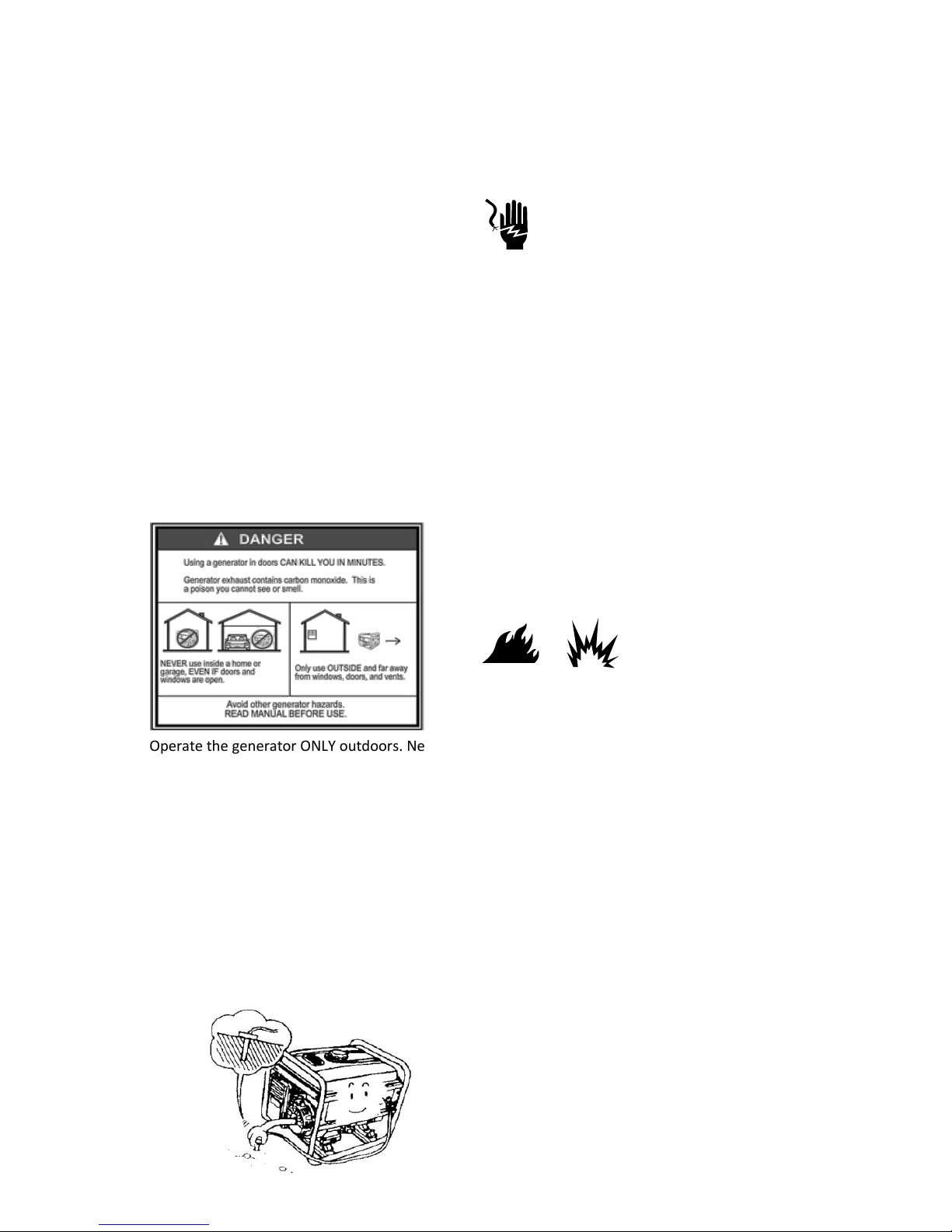
CARBON MONOXIDE WARNING
Operate the generator ONLY outdoors. Never
run the generator indoors as the engine gives
off poisonous carbon monoxide, an odorless and
colorless gas. Inhaling carbon monoxide will
cause nausea, fainting or death. Also, keep the
generator at least 3 feet away from flammable
ma tter fo r ade qua te ventila tion
GROUNDING THE UNIT
Always properly ground the generator. Failing to
do so can result in electrocution, particularly if
the generator is equipped with a wheel kit.
ELECTRIC SHOCK AND SHORT CIRCUIT
Be sure to notify the utility company
when using the generator for backup
power. Use approved transfer
equipment to isolate the generator from electric
utility. In highly con ductive area such as metal
decking or steel work, use a ground circuit fault
interrupter. Never touch the generator if the
generator is wet. Also, never touch the
generator if your hand is wet. Never operate
your generator if the weather conditions call for
any type of precipitation such as rain, snow, or
fog.
Do not use electrical cords that have been
damaged (worn, bare, frayed)
Do not touch bare receptacles or wires
Do not allow children to operate the generator.
FUEL SAFETY
When using the LPG generator, please be sure
that ther e is som e dis tance between LGP tank
and the LPG generator, to prevent unnecessary
danger because of the high temperature surface
area of the LPG tank. When using the unit,
please check the surface temperature of the
LP G t ank.
Place the generator in a well-ventilated area. DO
NOT place the generator near vents or intakes
where exhaust fumes could be drawn into
occupied or confined spaces. Carefully consider
wind and air currents when positioning
generator. Please do not light a cigarette near
the LPG generator.
GENERATOR SAFETY
Do not start g enerator with electr ica l d evices
conn ected to it. Start the gen erator first an d
after the speed of the generator stabilizes,
electrical loads can be applied to it.
When connecting electrical loads, make sure the
devices are "OFF" first before connecting them.
4
Keep the same concept when disconnecting
electrical devices; make sure all devices are in
the "OFF" position before disconnecting.
Operate the generator on level surfaces only.
Inclined surfaces reduce the effective lubrication
of the engine.
Do not expose the generator to excessive
moisture, dust, dirt, or corrosive vapors.
NOTICE poor treatment of your equipment
can greatly reduce the life of the LPG generator.
Use the generator for its intended usage. If you
have any concerns about maintain your unit
contact a local service center or called customer
service (888)-696-2345. Operate the LPG
generator on a level surface and do not place
objects in the units recoil slots.
Generator Specifications
Running Wattage
6000 Watts
Starting Wattage
7000 Watts
AC Load
120V/240V
Phase
Single
T.H.D.
<5%
Weight
193.8 lbs. (87.9 kg)
Height
23.31 inches (59.2
cm)
Wi dth
16.93 inches (42.0
cm)
Length
17.13 inches (43.5
cm)
Frequency
60Hz
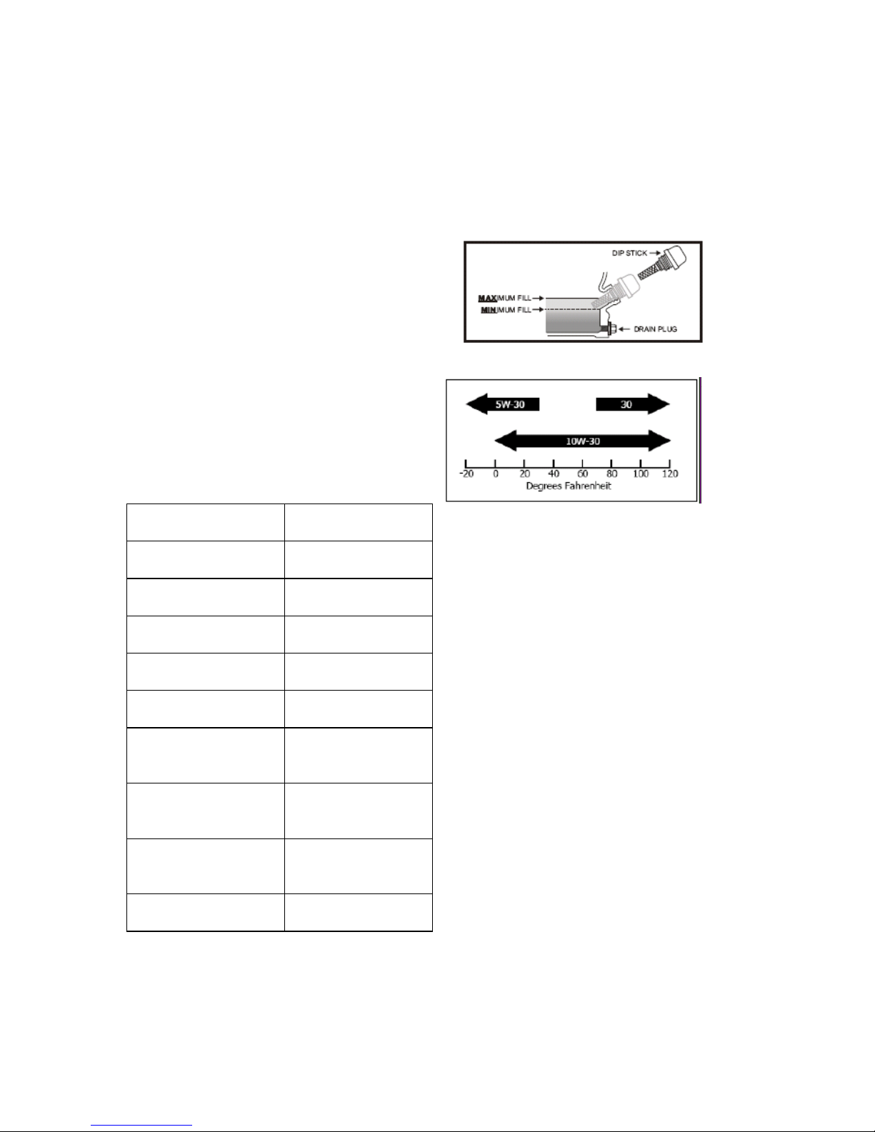
OIL
Change oil when the engine is warm. Refer to
the oil specification to select the proper grade of
oil for your operating environment.
1. Remove the oil drain plug with a 15 mm
socket and extension.
2. Allow the oil to drain completely.
3. Replace the drain plug.
4. Remove oil fill cap/dipstick to add oil.
5. Add 0.63 qt (0.6 L) of oil and replace oil fill
cap/dipstick.
6. Dispose of used oil at an approved waste
management facility.
Oil capacity is 1.16 qt (1.1 L).
SPARK PLUGS
1. Remove the spark plug cable from the spark
plug.
2. Use the spark plug tool that shipped with
your generator to remove the plug.
3. Inspect the electrode on the plug. It must be
clean and not worn to produce the spark
required for ignition.
4. Make certain the spark plug gap is 0.7 -
0.8mm (0.028 - 0.031 in.).
5. Refer to the spark plug recommendation
chart when replacing the plug.
6. Carefully thread the plug into the engine.
7. Use the spark plug tool to firmly install the
plug.
8. Attach the spark plug wire to the plug.
Your generator comes equipped with a ¾” long
reach plug (18 mm)
Intermittent use (less than 1 hour/month) or
colder temperatures (below 60°F)
N G K B 4 E S o r S T A R F 6 T C
Moderate use (less than 3 hours/month) or
Seasonal temperatures (50-80°F)
N G K B 4 ES or STAR F6TC
Extreme use (continuous) or hot climates(80100°F)N G K B 4 E S o r S T A R F 6 T C
5
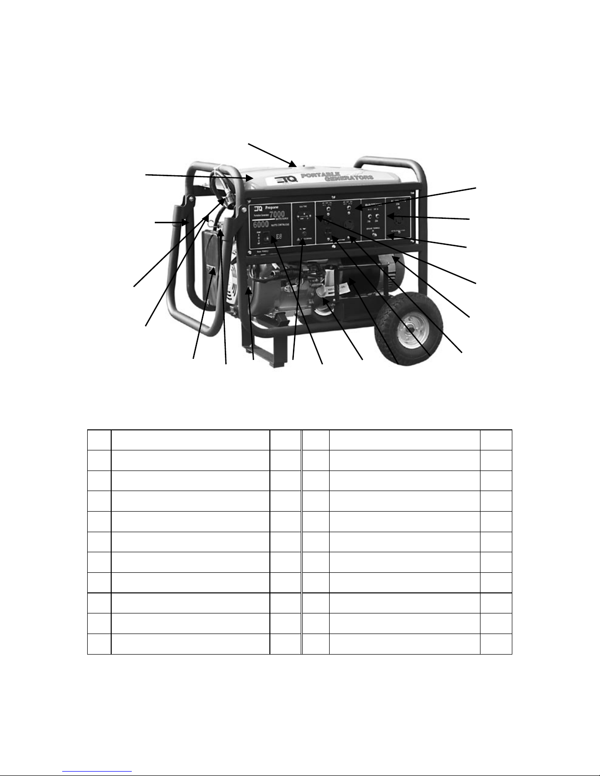
Controls and Features
Read this owner’s manual before operating your generator. Familiarize yourself with the location
and function of the controls and features. Save this manual for future reference.
NO.
D E S C R I P TI O N
Qty
NO.
D E S C R I P TI O N
Qty
1
AC CIRCUIT BREAKER 20A
1
11
OIL INDICATOR LIGHT ASSY
1
2
AC CIRCUIT BREAKER 30A
1
12
RECOIL STARTER
1
3
LUG GROUND
1
13
COCK ASSY.FUEL
1
4
HOUR METER
1
14
AIR CLEANER
1
5
BRACKET,RR.,MOTOR
1
15
CHOKE ROD
1
6
3-POLE RECEPTACLE L5-30R
1
16
T U B E , L P G
1
7
120V RECEPTACLE 5-20R
1
17
F R A M E C O M P
1
8
MOTOR ASSY.,STARTING
1
18
TANK TOP COMP,FUEL
1
9
CAP ASSY,OIL FILLER
1
19
REDUCTOR A S SY
1
10
ENGINE SWITCH
1
20
MUFFLER COMP
1
WARNING: DO NOT exceed the generator’s wattage/amperage capacity. Our products are
continuously being changed and improved. Every effort has been made to ensure that information
in the manual is accurate and up to date. However, we reserve the right to change, alter or
otherwise improve the product and this manual at any time without prior notice.
(1)
(2)
(3)
(4)
(5)
(6)
(7)
(8)
(9)
(10)
(11)
(12)
(13)
(14)
(15)
(16)
(17)
(18)
(19)
(5)
(6)
(7)
(4)
(1)
(2)
(3)
6
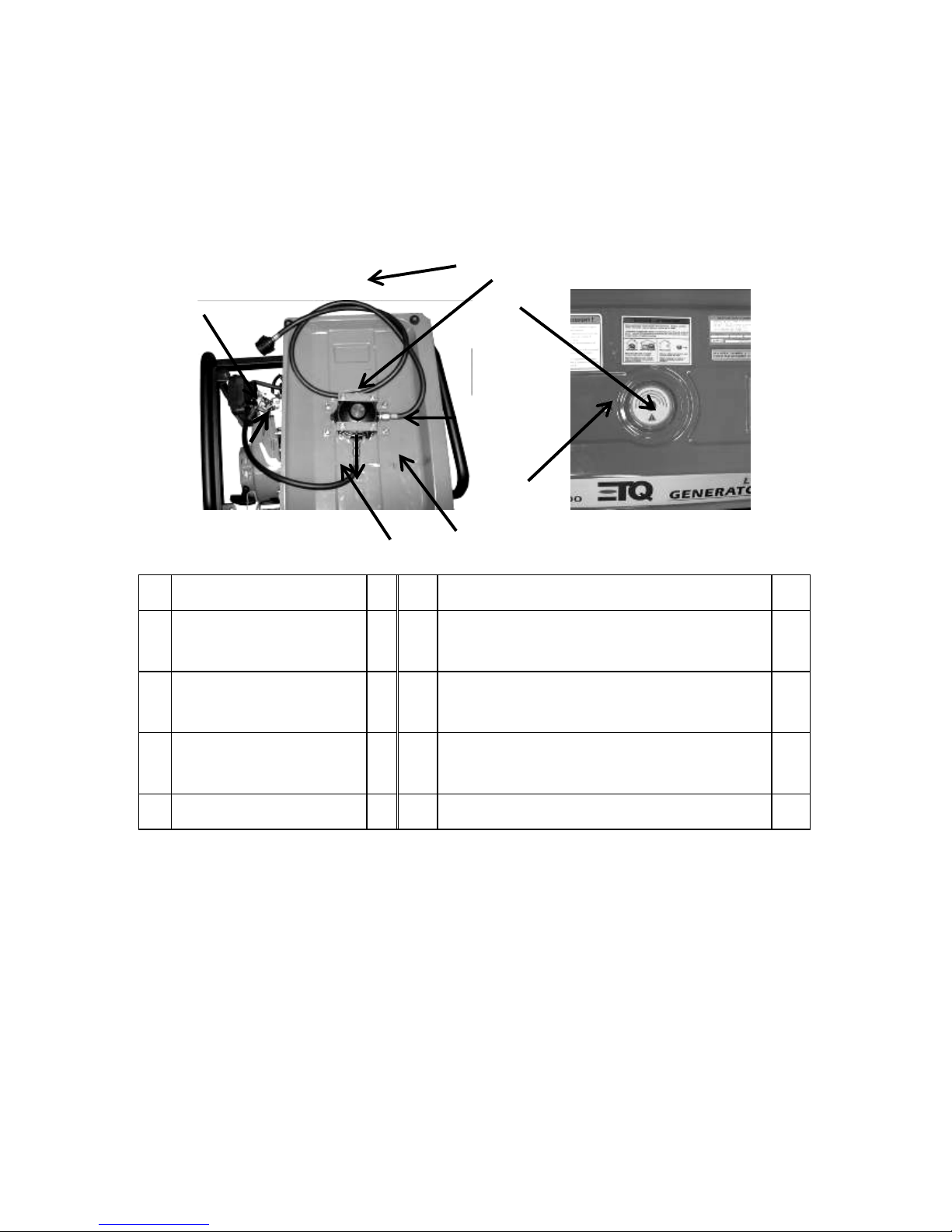
Operation instruction of REDUCTOR ASSEMBLY
Instruction on LPG denser device (bottom)
To develop cold start performance of LPG generator unit, the air REDUCTOR ASSY includes one LPG
denser device (bottom), the detailed operation of the bottom is shown below.
When starting the cold LPG generator unit, open the valve of the LPG tank, close the resistance air
valve handle, press the LPG denser device (bottom) lightly, and hold for 1-2 seconds, then stop.
Start the engine normally, and after finishing the start up, please open resistance air valve handle.
Parts
Included in with your unit are: (1) Flat head screwdriver, (1) Spark Plug Wrench, (1) 8 x 10 Wrench,
(1) 17x 19 wrench, (2) wheels, (1) axle, (1) handle bar, (1) leg stands
NO.
D E S C R I P TI O N
Qty
NO.
DESCR I P T I O N
Qty
1
High-pressure intake
tube(1000mm)
1 5 Mix device( the same as carburetor)
1
2
REDUCTOR ASSY
1
6
LPG denser device (bottom)→m ounted onto
REDUCTOR valve
1
3
TANK TOP COMP,FUEL
1
7
LPG air-pressure adjusting bottom→mounted
onto REDUCTOR valve
1
4
Low-pressure outlet tube
1
(1)
(2)
(3)
(4)
(5)
(6)
(7)
IN
OUT
7
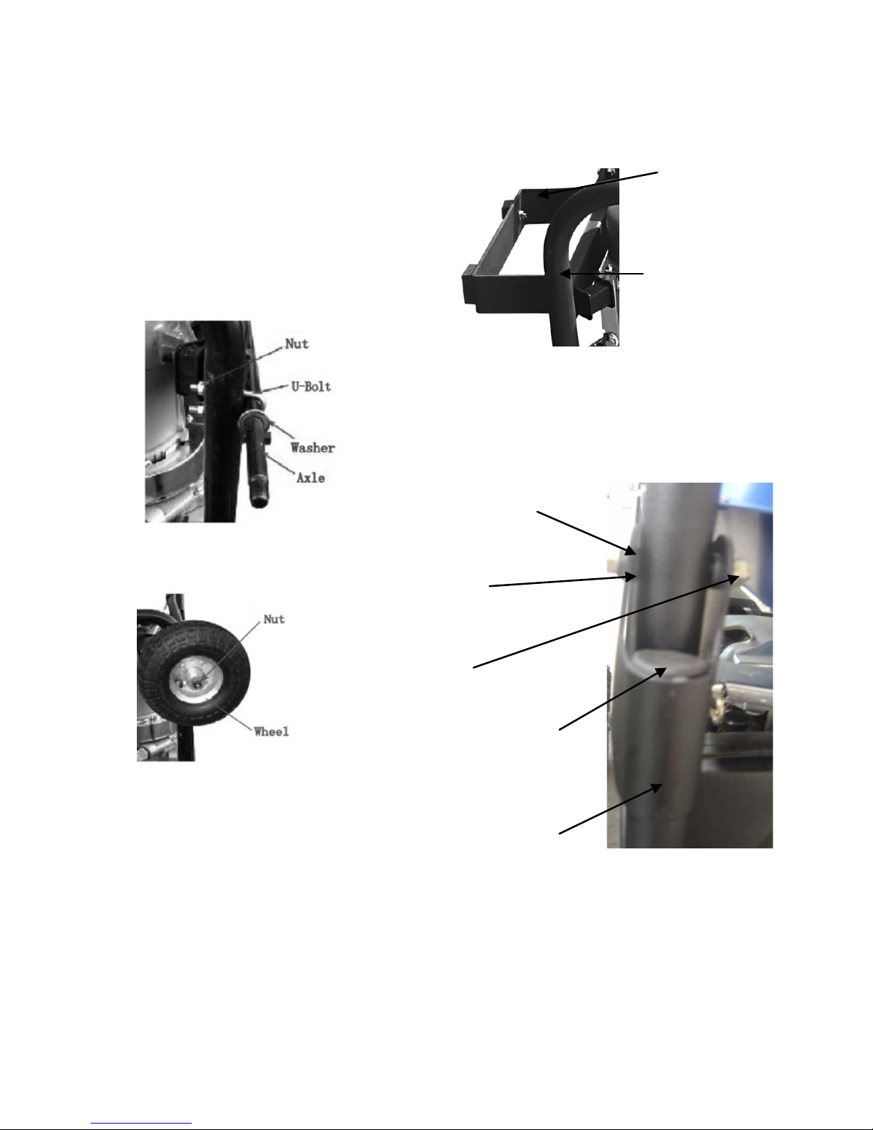
HANDLE AND WHEEL KIT ASSEMBLY
The wheel kit mist be assembled when there are
no liquids in the generator.
1. Place the generator on its side. (engine side
down).
2. Secure the axle with two u bolts.
3. Screw on the nuts onto the u-bolts to secure
the axle.
4. Place the washer onto the axle.
Place the wheel onto the axle.
Tighten down the wheel securely with a bolt.
1. Use the bolt and nut provided to secure the
foot tightly onto the frame of the generator.
2. Flip the generator back to its normal upright
position.
3. Now you are ready to install the handle bars.
1. Put the grips onto the handle bars.
2. Secure the bracket bolt and nut.
3.Make sure that the bracket is nicely tightened
down.
4. Place the handle bar into the bracket.
5. Secure with a bolt and nut
Foot
Bo lt + Nut
HANDLE PIPE COMP
IMMOBILITY PIECE TOP
NUT
WASHER
BOLT FLANGE
8
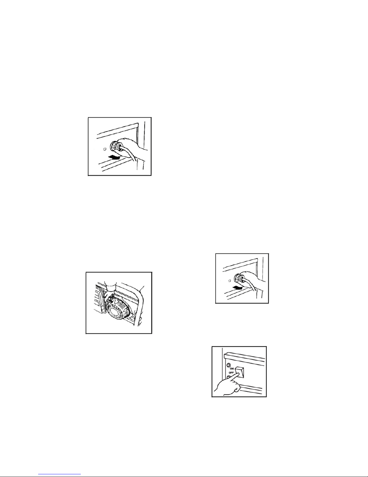
STARTING THE UNIT
Make certain the generator is on a flat, level
su rface.
2. Disconnect all electrical loads from the
generator. Never start or stop the generator
with electrical devices plugged in or turned on.
Disconnect electrical devices
3. Connect LPG tube to the LPG tank, and then
open the LPG valve slowly, till it totally open (to
insure no LPG leakage).
4. Move the choke lever to the “Choke”
position.
5. Press the denser bottom of the REDUCTOR
ASSY and hold 1~2 seconds;
6. Pull the starter cord slowly un til resistance is
felt and then pull rapidly
Recoil starting rope
7. As engine warms up, move the choke lever to
“Run”.
CONNECTING ELECTRICAL LOADS AND
ELECTRICAL CAPACITY
After sta rting th e gen erato r, let the engine
warm up after connecting electrical loads to it.
Do not have any electrical loads connected
befo re startin g the generat or.
Make sure all electrical devices are 60 Hz
devices.
Do not connect 50 Hz devices to the generator.
Do not connect 3-phase loads to the generator.
Do not overload the generator.
Before beginning your work, you must verify
that the rated (running) and surge (starting)
watts for the items you will power at the same
time are within the generators operating
capacity. Please refer to the following Table 1
for wattage / amperage ratings. Also, to prolong
the life of your generator, prolong the life of
your generator, sequentially add loads and
permit the generator to stabilize before adding
another load. Never exceed the capacity of the
generator.
Es timate how ma ny su rge ( starting) wat ts you
will need. Surge wattage is the short burst of
power needed to start electric motor-driven
tools or appliances such as a circular saw or
refrigerator.
Stopping the Engine
1.Turn off and unplug all electrical loads. Never
start or stop the generator with el ectri cal
devices plugged in or turned on.
2.Let the generator run at no-load for several
minutes to stabilize internal temperatures of the
engine and generator.
3. Turn the ignition switch to the “Off” position.
4.Turn the fuel valve to the “Off” position.
9
MAINTENANCE
Generator maintenance consists of keeping the
unit clean and dry. Be sure to store the unit in a
clean and dry environment, where it will not be
exposed to excessive dust, dirt, moisture or any
corrosive vapors. Cooling slots should always be
clean and free from clogs.
Note: Do not use a garden hose to clean the
generator. Water can enter the fuel and intake
system and cause problems. In addition, if water
and dirt buildup on the generators internal
windings, the resistance of these windings will
decrease.
• To clean the generator, use a damp cloth
to wipe the exterior surfaces.
• Use a soft bristle brush to loosen caked on
dirt of oil.
• Use a vacuum cleaner to pick up loose dirt
and debris.
• Compressed air (not to exceed 25 psi) may
be used to blow away dirt.
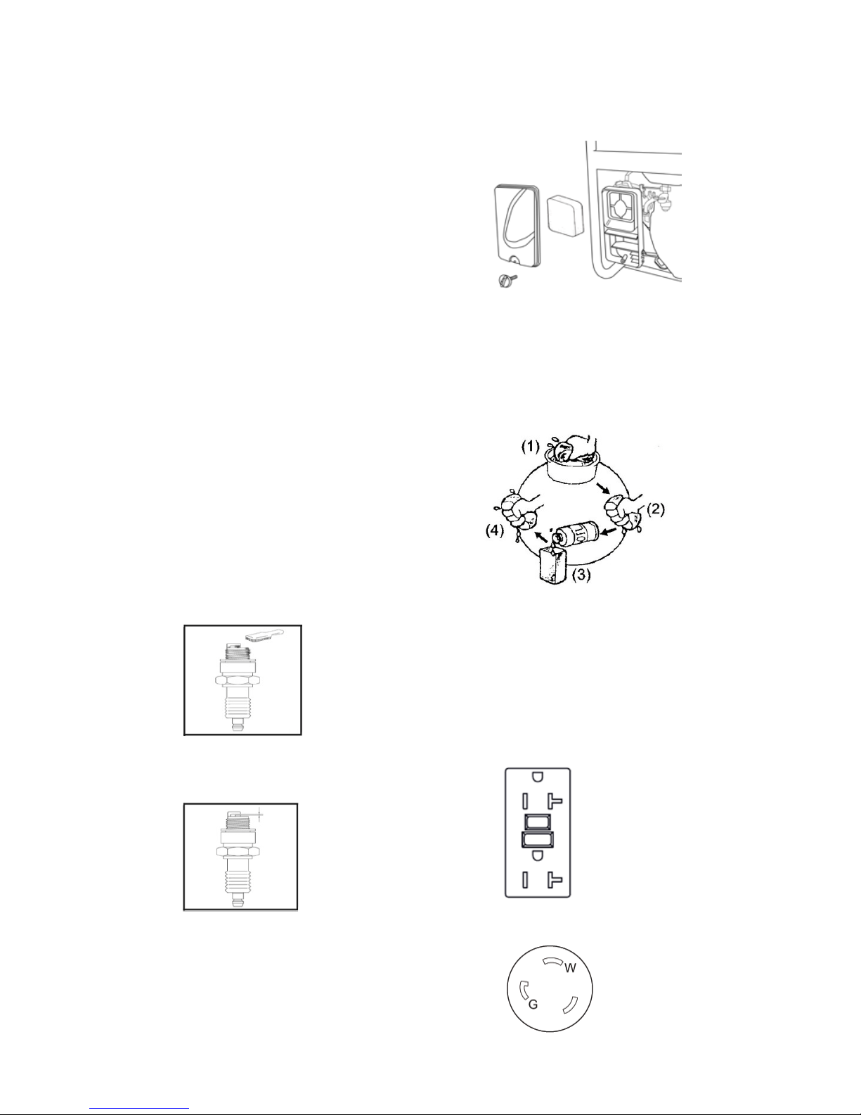
S PA R K P LU G
• Remove the spark plug
• Remove the carbon deposits
• Check for discoloration. Standard is tan in
color.
• Check spark plug gap
Make certain the spark plug gap is
0.7 -0.8mm (0.028 - 0.031 in.).
AIR FILTER
• Unscrew the bolt from the air cleaner
cover, and re move the air cleaner cover.
• Check the air cleaner element to be sure
they are clean and in good condition.
• If the air filter is dirty, remove and clean
the element.
• Wash in solvent
• Squeeze
• Soak oil
• Squeeze dry
• Reinstall the air cleaner element and
secure the cover by setting the cover
spring.
RECEPTACLES
This generator is equipped with the following
Receptacles
NEM A 5-20R: 12 5 V o l t , 2 0 A m p G F C I D u p l e x
Receptacle
L5-30R: 120Volt, 30Amp Twist Lock Receptacle

10
TROUBLE SHOOTING
P ro b le m
Ca use
So lut ion
Gene rator will no t start
No Propane
New Tank
Faulty spark plug
Replace spark plug
Unit loaded during start up
Remove load from unit
Gene rator will no t start;
Generator starts but runs
roughly
Low oil level
Fill crankcase to the proper level
Place generator on a flat, level
su rface
Choke in the wrong
position.
Adjust choke.
Spark plug wire loose
Attach wire to spark plug
Generator shuts down
during
operation
Out of Propane
Refill propane
Low oil level
Fill crankcase to the proper lev el.
Place generator on a flat, level
su rface
Generator cannot supply
enough
power or overheating
Generator is overloaded
Review load and adjust. See “Power
Management”
Insufficient ventilation
Check for air restriction. Move to a
well ventilated area
No AC output
Cable not properly
connected
Check all connections
Connected device is
defective
Replace defective device
Circuit breaker is open
Reset circuit breaker
Capacitor defective
Replace capacitor (Service Center)
Faulty brush assembly
Replace brush assembly (Service
Center)
Fa ulty AVR
Replace AVR (Service Center)
Loose wiring
Inspect and tighten wiring
connections
Other
Contact the help line.
Generator gallops
Engine governor defective
Contact the help line
Repeated circuit breaker
tripping
Overload
Review load and adjust. See “Power
Management”
Faulty cords or device
Check for damaged, bare or fray ed
wires. Replace defective device
 Loading...