

ETQ 170F, 170FSE, 178F, 178FE, 178FS Owner's Manual
...
OWNER’S MANUAL
AIR-COOLED DIESEL ENGINE
170F / FE / FS / FSE 178F / FE / FS / FSE 186F / FE / FS / FSE
1

PREFACE
Thank you for purchasing products from Eastern Tool & Equipment, INC. The following
manual is only a guide to assist you and is not a complete or comprehensive manual of all
aspects of maintaining and repairing your engine. The engine you have purchased is a complex
piece of machinery. We recommend that that you consult with a dealer if you have doubts or
concerns as to your experience or ability to properly maintain or repair your engine. You will
save time and the inconvenience of having to go back to the store if you choose to write or call
us concerning missing parts, service questions, operating advice, and/or assembly questions.
Engine Features and Highlights
• Direct fuel injected intake system
• Recoil-type manual starter and or optional electric starter system
• Forced air convection cooling system
• Composite steel fan cover for minimum noise levels
Our four stroke diesel engines are air cooled with a direct fuel injected intake system. They offer
maximum efficiency through the minimal conservation of energy and materials. These diesel
engines are compact and lightweight. They are easily maintained and portable making it
convenient to move. They are widely used as a source of mechanical power for industrial,
agricultural, and machinery equipment. Some applications include irrig ation equipment, diesel
powered pressure sprayers, grass-cutting machines, and soil-sampling machines. Other
applications include vibration rammers, shock rammers, marine engines, lightweight transport
vehicles, portable compressors, and lightweight portable generators.
This operating manual will explain how to operate and maintain your series of engines. Please
read it before running the engine for correct operation.
To ensure long engine life please follow the operating requirements listed in this manual.
If you have any questions or suggestions about this manual, please contact your local dealer or
us. Consumers should notice that this manual might differ slightly from the actual product as
more improvements are made to our products. Some of the pictures in this manual may differ
slightly from the actual product as well. Eastern Tools and Equipment, Inc. reserves the right
to make changes at any time without notice and without incurring any obligation.
2

TABLE OF CONTENTS
Page number
Safety Precautions 4
Chapter 1 Technical Specifications and Data 7
1-1 Technical Specifications 7
1-2 Overall Dimensions and Installation Conditions 9
1-2.1 Belt wheel and engine clearance requirements 10
1-2.2 Crankshaft driving angle conditions 11
1-2.3 Engine electrical system 11
1-3 Diesel engine shaft specifications 12
1-4 Diesel engine part names 13
1-5 Valve timing, initial angle of fuel delivery and valve clearances 14
1-5.2 Initial angle of fuel delivery 14
1-5.3 Valve clearances 14
1-6 Temperature ranges for exhaust and injection pressure specifications 14
1-7 Various engine torque specifications 15
Chapter 2 Diesel Engine Operation Procedures 16
2-1 Engine safety precautions 16
2-2 Fuel choices 16
2-3 Starting the diesel engine 19
2-3.1 Recoil Starting 19
2-3.2 Electric starter 21
2-3.3 Cold starting 21
2-4 Running and stopping the diesel engine 23
2-4.1 Running the diesel engine 23
2-4.2 Routine checks while engine is running 23
2-4.3 Stopping the engine 23
Chapter 3 Technical Maintenance of Diesel Engine 25
3-1 Daily checks and maintenance 25
3-2 Regularly checks and maintenance 25
3-3 Storing the engine for long periods of time 27
Chapter 4 Part Listings 29
4-1 Engine block 30
4-2 Cylinder head assembly 33
4-3 Piston connecting rod and crankshaft balancing mechanism 36
4-4 Fuel system parts 39
4-5 Oil and speed control system 41
4-6 Cooling and recoil starting system 44
4-7 Air cleaner and silencer system 47
Chapter 5 Engine Troubleshooting 50
5-1 Engine is not starting 50
5-2 Diesel engine lacks power 51
5-3 Engine stops automatically 51
5-4 Engine exhaust very black 51
5-5 Engine exhaust very blue 51
5-6 Engine exhaust white 52
5-7 Various methods of checking to see if engine is malfunctioning 52
Limited Warranty 53
Registration Card 55
Comment Card 55
3
SAFETY PRECAUTIONS
Please be sure to follow each instruction carefully
EXHAUST PRECAUTIONS
• Never inhale the exhaust gases, it contains
carbon monoxide, a colorless, odorless and
extremely dangerous gas which can cause
unconsciousness or death
• Never operate the engine indoors or in a
poorly ventilated area, such as a tunnel or
cave, etc.
• Exercise extreme care when operating the
engine near people or animals. Keep the
exhaust pipe free of external objects.
REFUELING PRECAUTIONS
• Be sure to stop the engine before refueling.
• Do not overfill the fuel tank.
• If fuel is spilled, wipe it away carefully and
wait until the fuel has dried before starting
the engine again.
• When changing oil, make sure that the fuel
cap is tightly secured to prevent fuel
leakage.
4
FIRE PREVENTION
• Never operate the engine while
smoking or near an open flame.
• Never use the engine around dry brush,
twigs, cloth-rags, or other flammable
materials.
• Keep the engine at least 3 feet (1 meter)
away from buildings or other
structures.
• Keep the engine away from flammables
and other hazardous materials.
PROTECTIVE COVER
• Always place the protective covers
over the rotating parts. If rotating parts
such as the driving pulley, belts, and
shafts are exposed, serious injuries can
be caused. To prevent injury, please
equip all rotating parts with protective
covers.
• Be careful of hot parts. The muffler
and other engine parts can become very
hot while the engine is running or after
the engine has been run. Always
operate the engine in a safe area and
keep children away from running
engines.
5
SURROUNDINGS
• Operate the engine on a table or level
surface free of small rocks and loose
gravel.
• Operate the engine on a level surface. If
the engine is tilted, fuel may spill from the
gas tank.
NOTE: Operating the engine at a steep incline
may cause the engine to seize up due to
improper lubrication even when the oil level is
a maximum.
• Be careful of fuel spillage when
transporting the engine. Always tighten
the fuel cap and close the fuel strainer cock
before moving the engine around.
• Never move the engine while it is in
operation.
• If the engine will be transported over a
long distance, drain all the fuel from the
fuel tank to prevent fuel leakage.
PRE-OPERATION CHECKS
• Carefully check fuel pipes and fuel joints
for fuel leakage. Leaked fuel creates a
dangerous situation.
• Verify that all the nuts and bolts of the
engine are tights. A loose nut or bolts may
cause serious engine failure and could lead
to serious injuries.
• Always check the engine oil and refill it if
necessary.
• Always check the fuel level and refill it if
necessary. Never overfill the fuel tank
• Avoid wearing dangling or long clothes
such as loose aprons, towels, and waist
belts, as these items may be caught in a
rotating part of the engine.
6

Chapter 1 Technical Specifications and Data
1-1 Technical specifications in English Units
Model
Item
Type Single vertical cylinder, 4-stroke, air-cooled, direct injection
Bore x Stroke (in.) 2.76 x 2.17 3.01 x 2.44 3.39 x 2.76
Displacement (cu. in.) 13.36 18.67 25.51
Speed (rpm) 3600 3600 3600
Continuous 4.0 5.9 8.85 Output
(HP)
Maximum 4.5 6.6 9.85
170F 178F 186F
Fuel tank capacity
(US gallons)
Full 27.1 37.17 55.75 Lube-oil
Capacity
(oz)
Crankshaft direction Clockwise from flywheel end
Cooling type Forced air cooled by flywheel fan
Lubrication type Pressure splash
Starting system Recoil manual start and or optional electric start
Dry weight (recoil) (lbs) 60 73 106
Dry weight (elec.) (lbs)
Dimensions (LxWxH)
(inch)
Effective 8.45 13.51 20.27
13.1 x 14.8 x 16.3 15.1 x 16.6 x 17.7 16.4 x 17.4 x 19.5
.66 .9 1.45
68 84 117
7

Technical specifications in SI units
Model
Item
Type Single vertical cylinder, 4-stroke, air-cooled, direct injection
Bore x Stroke (mm) 70 x 55 78 x 62 86 x 70
Displacement (cc) 211 296 406
Speed (rpm) 3600 3600 3600
Continuous 2.98 4.4 6.6 Output
(kw)
Maximum 3.36 4.92 7.3
170F 178F 186F
Fuel tank capacity
(Liters)
Full .8 1.10 1.65 Lube-oil
Capacity
(L)
Crankshaft direction Clockwise from flywheel end
Cooling type Forced air cooled by flywheel fan
Lubrication type Pressure splash
Starting system Recoil manual start and or optional electric start
Dry weight (recoil) (kg) 27 33 48
Dry weight (elec.) (kg)
Dimensions (LxWxH)
(mm)
Effective .25 .40 .60
332 x 376 x 415 383 x 421 x 450 417 x 441 x 494
2.5 3.4 5.5
31 38 53
8

1-2 Overall engine dimensions
Installation Conditions
(1) There must be a tight stationary foundation for the diesel engine to avoid vibrations or
movement when the engine is running. For prolonged engine life, consider using some
type of motor mount.
(2) Make sure that the centering position of the output shaft is properly aligned.
9
(3) Verify that the dimensions of the hole on the belt wheel and keyway shaft match or
correspond with each other. Also make sure that the bolt of the engine shaft is
tightened to the proper torque specifications.
(4) When the engine is matched with other belt driven machines, the total desired belt
distance traveled by the driven wheel must equal the total distance travele d by the
driver wheel. If this is not properly calculated and matched, the desired speed on the
driven wheel will be incorrect. A formula used to calculate the necessary diameters of
the various wheels is provided below.
The diameter of driving wheel (belt wheel) can be calculates as follows:
Diameter of engine driving wheel (engine pulley) =
Diameter of driven machine x speed of driven machine
Diesel speed (engine speed)
(5) Make sure that the belt has a correct tension to it.
Note: If the belt is to tight, the engine bearings will wear at a high rate leading to engine failure.
If the belt is to loose, the belt will slip at high speeds and high loads causing high pitch whistling
noises.
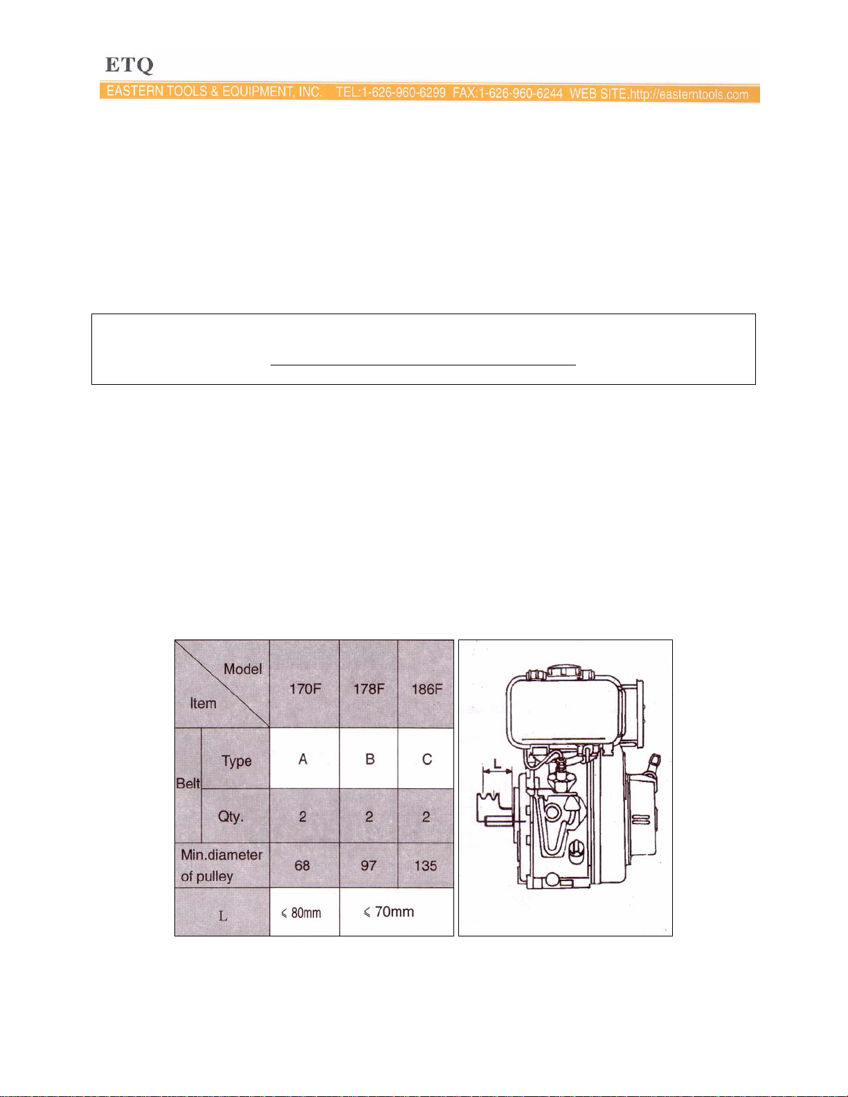
1-2.1 Allowed clearance between belt wheel and engine
The belt pulley wheel should be as close to the engine as possible. The values of L are tabulated
in table 1-1.
Table 1-1. Allowed belt pulley wheel to engine distances.
10
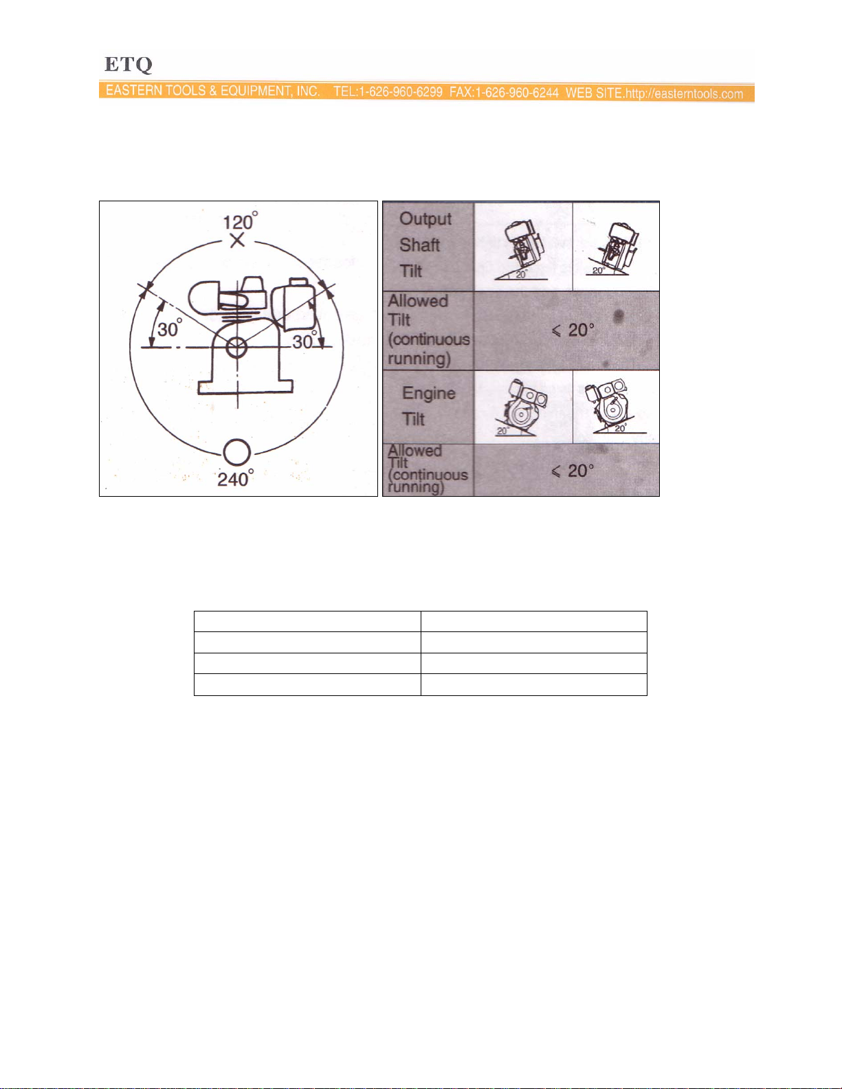
1-2.2 Crankshaft driving angles must be less than 120o, see Fig 1-1
The tilt must be kept within the allowed values shown in Fig 1-2
Fig 1-1. Allowed driving angles. Fig 1-2. Allowed tilt angles.
1-2.3 Please contact our dealers about the electric circuits involved with this engine.
We recommend the use of accumulators rated at 20 hours shown in table 1-2.
Table 1-2.
Model Units: (amp-hours)
170F 18~24
178F 24~26
186F 36~45
11
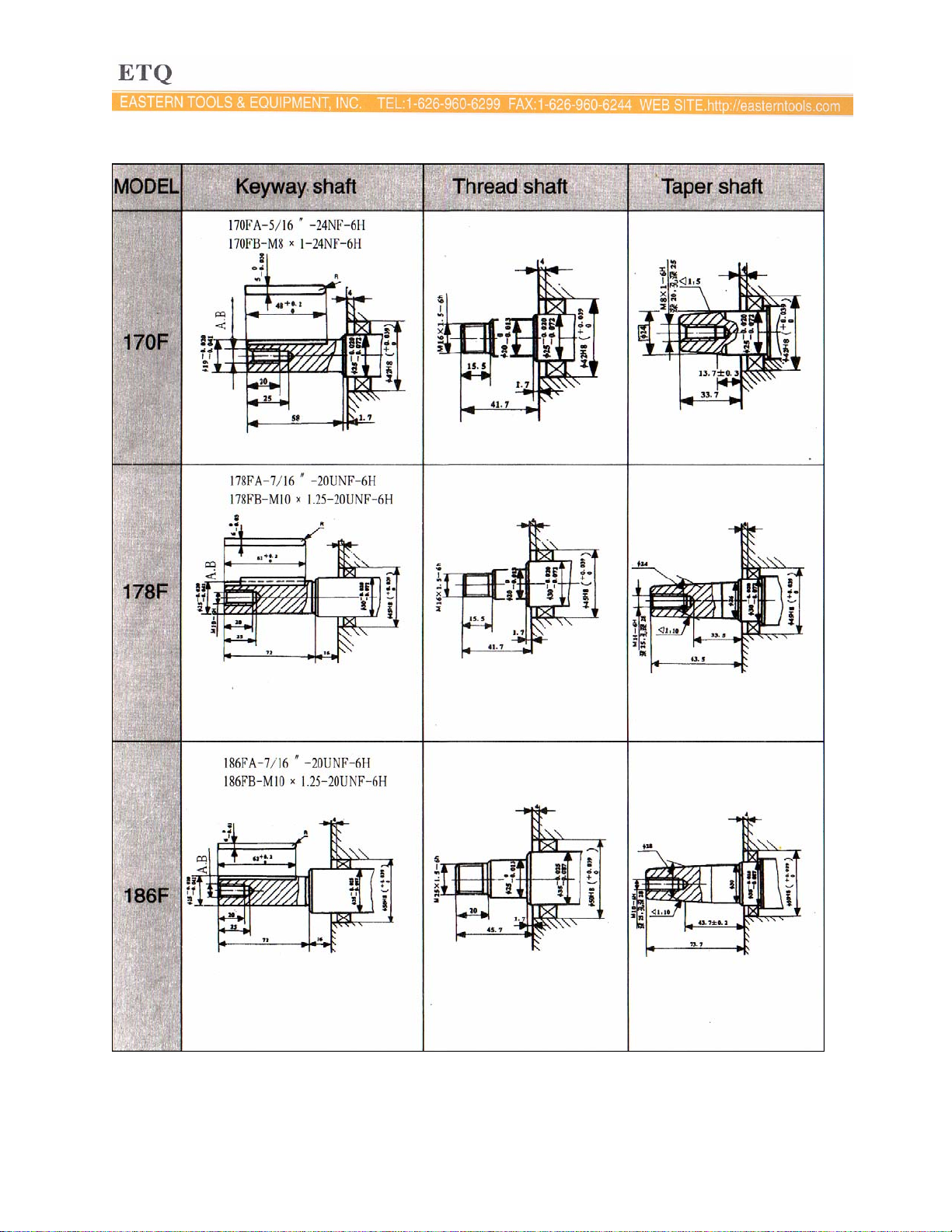
1-2 Diesel Engine shaft specifications units: mm
12
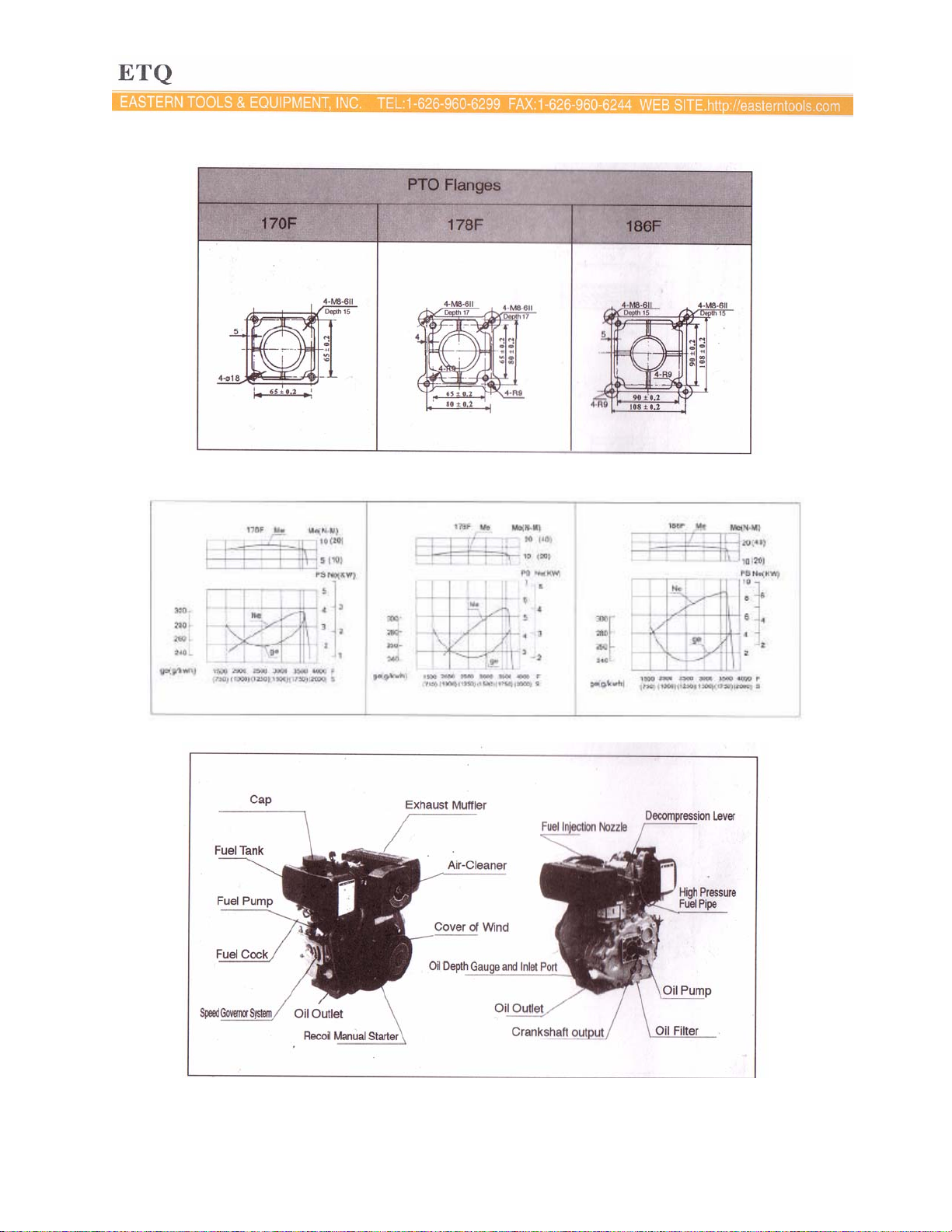
Sizes of PTO flanges
Diesel Engine Power Curves
1-4 Names of Diesel Engine Parts
13
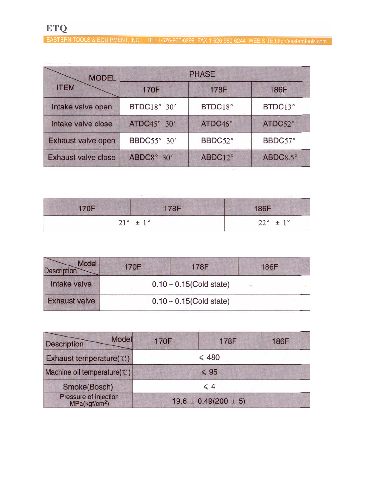
1-5 Valve timing, initial angle of fuel delivery and valve clearances. Units: Degrees
Table 1-3.
1-5.2 Initial angle of fuel delivery Units: Degrees
Table 1-4
1-5.3 Valve Clearances
Table 1-5
1-6 Temperature ranges for exhaust and injection pressure specifications
14
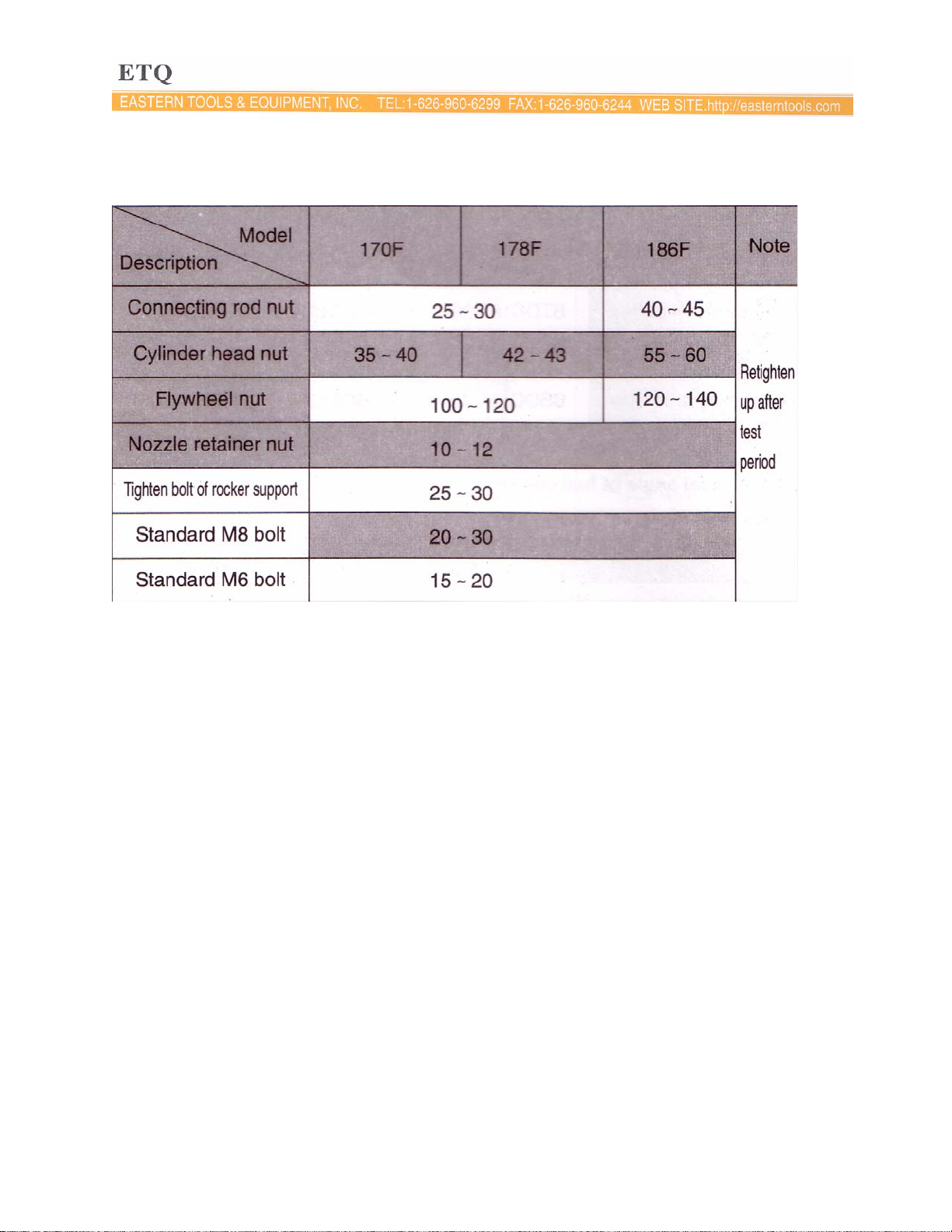
1-7 Torque specifications for various engine nuts and bolts
Table 1-7. Torque specifications in SI units Units: N m
15
CHAPTER 2 DIESEL ENGINE OPERATION
2-1 Please pay close attention for safe operation of the diesel engine.
1. The fuel used must be filtered by silk fabric or settled for 24 hours before it is used in the
engine. Never add oil to the crankcase when the engine is running.
2. Keep flammable and combustible goods away from engine while engine is running. The
engine should be placed in a simple ventilated place.
3. Do not touch the muffler when the engine is running or just after it has stopped.
4. The diesel engine should be operated at its rated power and rated speed. If abnormal
operating conditions are detected, stop the engine immediately to check and fix the
problem.
5. A new engine must be properly broken in. For the first 20 hours, run the engine at low
speed and low loads. Do not allow engine to run at high speeds and high loads during the
break in period.
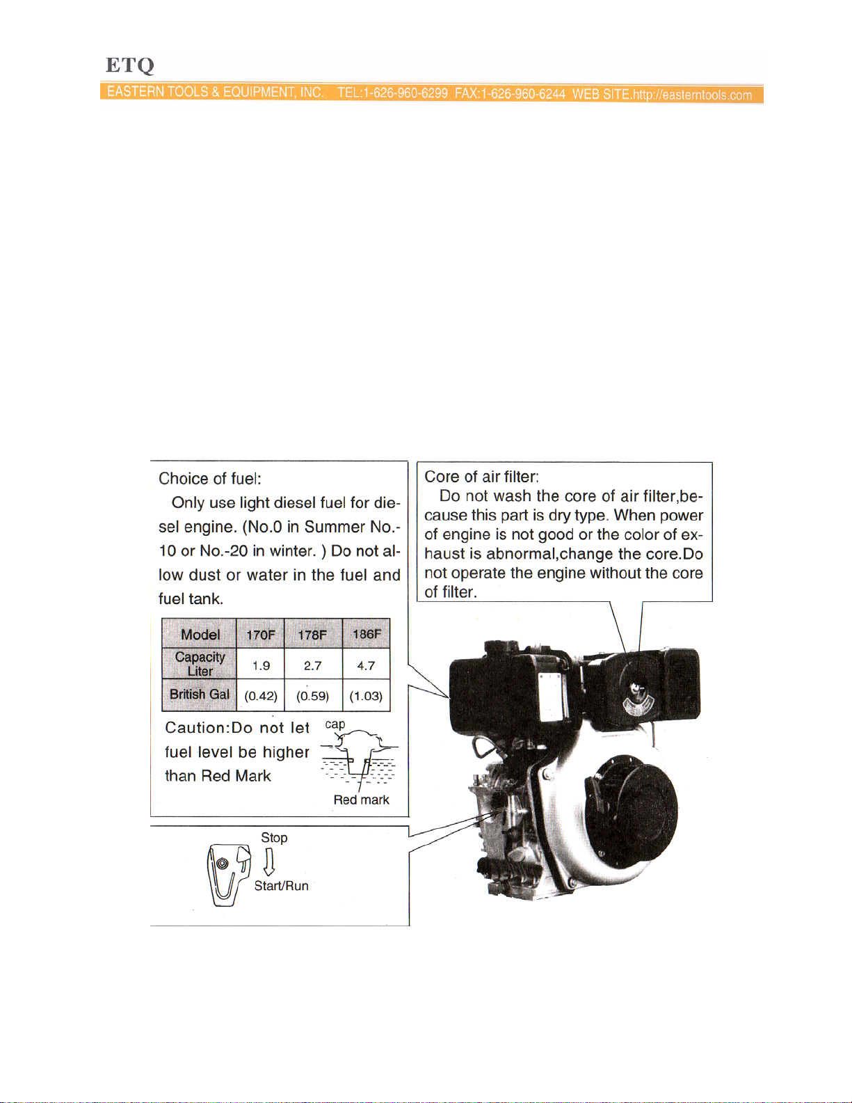
2-2 Fuel Choices
16

Oiling plug:
In winter, if it is difficult to start the
engine, pull the plug out and fill 2cc of lube oil
into the hole and then put the plug back in
place. Make sure the plug is tight, if not, the
engine can absorb dust into the combustion
chamber and damage itself.
Muffler
The factory has replaced the
engine fuel and engine oil
once already. To check the
fuel pipeline, make sure the
fuel line is completely
drained. IF there is air in the
pipeline, drain it out. To do
this, loosen the nut between
the injection pump and fuel
pipe, then drain out the air
until there are no bubbles
left in fuel line.
Compression release lever:
Push the lever down
to start the engine
Oil Lubricant Inlet:
Place the engine on level ground and fill the lubricant into the inlet. When checking the
oil level, gently place the dipstick into the oil. Do not turn the oil scale.
17
 Loading...