

Etiger Digital Technology ES D1A Users manual
ES-D1A
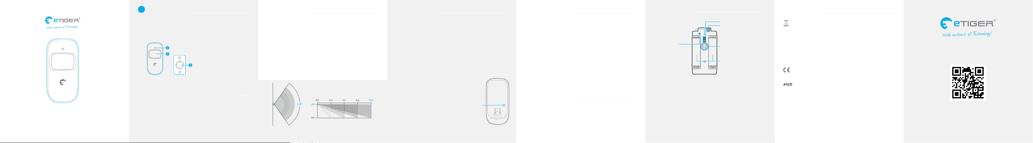
Wireless Motion Detector
www.etiger.com
EN
Box Content
1 x PIR Motion Detector
1 x Bracket
1 x User Manual
1. Detection window
2. LED indicator
3. Bracket
Before Using for the First Time
Open the case and remove the battery activation strip to activate the
batteries. Self-testing starts for 30 seconds.
Images, illustrations and text are non-contractual. ETIGER and the ETIGER logo are
registered trademarks and the property of ETIGER.
Copyright © 2014 ETIGER. All rights reserved.
Installation
Fix the bracket on the wall with screws and attach the detector to the
bracket. Adjust the bracket to change the detection distance and angle.
It is recommended to mount the detector 2m from the ground.
Avoid mounting the detector close to windows, air conditioner, heater,
refrigerator, oven, sunshine and places where the temperature changes fast
or where the air stream ows frequently.
If two detectors are installed in the same detection scope, adjust the
location to avoid interferences and false alarms.
The detector is more sensitive to cross movements than vertical movements.
Top view
Detection scope
Side view
Mode Setting
Testing mode
Once the self-testing is complete, long press the test button. The sensor
switches to testing mode, and scans once every 10 seconds. After 3
minutes, the LED blinks twice, and the sensor switches to working
mode.
Working mode / Stand-by mode
In working mode, if the sensor is triggered more than twice within 3
minutes, it will switch to standby mode to save power. If no movement
is detected within the next 3 minutes, the sensor goes back to working
mode.
Register the detector in the alarm system
Switch to Connection Mode on the control
panel. Press the test button of the sensor
twice. The control panel beeps once: the
motion detector is registered. If you hear
two beeps, the detector has already been
connected.
To check if the registration is complete, arm
the system and trigger the sensor again.
If the siren rings out, the registration is
successful.
Test
Button
Specications
Power Supply:
DC 3V (AA 1.5V LR6 x2)
Static current:
≤90uA
Transmitting current:
≤9.5mA
Transmission distance:
≤ 80 m (in open area)
Radio-frequency:
315MHz (±75KHz)
Housing material:
ABS plastic
Operating conditions:
Temperature: -10°C ~ +55°C
Relative Humidity: ≤80% (non-condensing)
Detector dimensions:
107 x 53 x 32 mm
Bracket dimensions:
52 x 30 x 26.5 mm
LED indications
Blinks continuously: Self-testing
Blinks once: An intruder is detected
Blinks twice: Self-testing is complete; entering working mode.
Blinks 3 times every 3 seconds: Under-voltage indication: the batteries
must be replaced (the user will be informed by SMS when the batteries
are low if the detector is registered in the control panel).
PCB Layout
Jumpers for Zone setup
LED working indicator
Antenna
Infrared sensor: Detects the infrared rays released by human body
motion. Do not touch the surface. Keep the surface clean.
Tamper switch: When the alarm system is armed, the tamper switch
will trigger the alarm if the case is opened.
Jumpers for Zone setup: The jumpers enable you to assign the
detector to a specic zone. Refer to the user manual of your alarm
system for more information on zone set up.
Tamper switch
Infrared sensor
AA 1.5V LR6
Standards
This product bears the selective sorting symbol for waste electrical
and electronic equipment (WEEE). This means that this product must
be handled pursuant to European Directive 2002/96/EC in order to be
recycled or dismantled to minimize its impact on the environment. For
further information, please contact your local or regional authorities.
Electronic products not included in the selective sorting process are
potentially dangerous for the environment and human health due to
the presence of hazardous substances.
In compliance with European laws.
This product was designed and manufactured in compliance with
Directive 2002/95/EC of the European Parliament and of the Council on
the restriction of use of certain hazardous substances in electrical and
electronic equipment (RoHS Directive - RoHS) and is deemed to comply
with the maximum concentration values set by the European Technical
Adaptation Committee (TAC).
Manufactured in China.
This user manual is available in other languages at
www.etiger.com/eu/support
Rue de la Loi, 25, 7100 La Louvière, Belgique
ETIGER EUROPE
service@etiger.com
ES-D1A-UM-EN20140724-1.1-W

FCC Information and Copyright
This equipment has been tested and found to comply with the limits for a Class B digital device,
pursuant to part 15 of the FCC Rules.
These limits are designed to provide reasonable protection against harmful interference in a residential
installation. This equipment generates,
uses and can radiate radio frequency energy and, if not installed and used in accordance with the
instructions, may cause harmful interference
to radio communications. However, there is no guarantee that interference will not occur in a particular
installation. If this equipment does
cause harmful interference to radio or televisi on reception, which can be determined by turning the
equipment off and on, the user is
encouraged to try to correct the interference by one or more of the following measures:
—Reorient or relocate the receiving antenna.
—Increase the separation between the equipment and receiver.
—Connect the equipment into an outlet on a circuit different from that to which the receiver is
connected.
—Consult the dealer or an experienced radio/TV technician for help.
15.19 Labelling requirements.
This device complies with part 15 of the FCC Rules. Operation is subject to the
following two conditions:
(1)This device may not cause harmful interference, and
(2) this device must accept any interference received, including interference that may
cause undesired operation.
changes or modifications not expressly approved by the party responsible for compliance could
void the user's authority to operate the equipment.
 Loading...