

Page 1
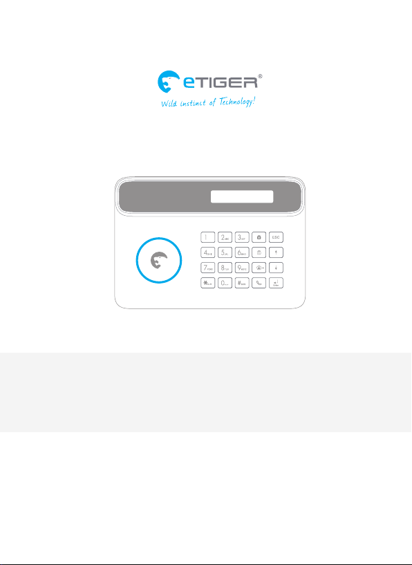
S4 Combo Secual / S4 Combo Vid Secual
GSM and Landline Alarm System
www.etiger.com
Page 2

Features
- GSM/PSTN transmitter
- Supports up to 30 remote controls, 50 wireless accessories and 50 RFID tags
- Can store up to 5 phone numbers, 5 SMS numbers, and 2 CMS numbers (for systems
connected to a Central Monitoring System)
- Arm / disarm the system by SMS, phone call, or App (on iOS or Android)
- Can be disarmed by RFID tag
- Built-in siren (100dB) and call function from the panel
- SMS alerts for power failure, power recovery and low battery
- Audio surveillance of the site from distance
- 2 x 800mAh lithium batteries included (8h battery life in standby mode)
Specications
Product name
S4 Combo Secual
SKU
S4-C
Control panel power supply
Input: AC 110-240V / 50-60 Hz
Output: DC 12V / 1 A
GSM working frequency
850 / 900 / 1800 / 1900 mHz
Radio-frequency
315MHz (±75KHz)
Standby current
110ma
Box Content
S4 Control Panel x1
Motion Detectors x2
Door / Window Contacts x2
Remote Controls x2
RFID Tags x2
PSTN Cable x1
PSTN Adaptor x1
2
Alarm current
340mA
Backup batteries
Lithium Batteries: 3.7V / 800 mAh x 2 (BL-5B)
Internal siren
100dB
Housing material
ABS plastic
Operating conditions
Temperature: -10°C~55°C
Humidity: ≤ 80% (non-condensing)
Control panel dimensions (L x W x H)
188 x 132 x 26 mm
AC Adaptors x1
Documentation x1
S4 Combo Vid Secual
+ IP Camera x 1 (with AC Adaptor and manual)
Page 3
Quick Start-up
Page 4
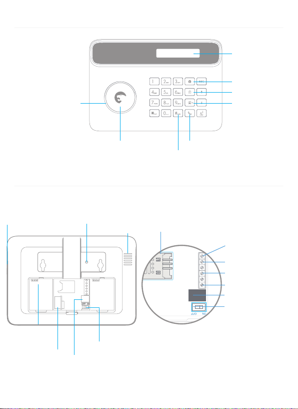
Control Panel Layout (Front)
VCC
Z1
GND
SP
GND
LOCK P1
LED Status Indicator
(armed / disarmed)
LCD Display
Arm
Disarm
Stay (Home Mode)
Control Panel Layout (Back)
Tamper Switch
Power Supply Interface
Monitoring MIC
Battery
Compartment
Telephone Interface
4
RFID Tag Reader
Speaker
Power Switch
SOS
SIM card Slot
Call
Output for
wired sensors
Wired sensors (24h zone)
Wired siren 500mA
Electronic lock
Adapter interface
Power On/O
Page 5
Connect your System
The S4 Combo Secual features a dual GSM and PSTN transmitter. This means that the control
panel of your alarm system will communicate with you either through a SIM card (GSM
module) or through your telephone landline (PSTN module).
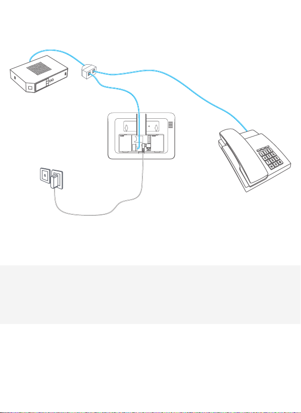
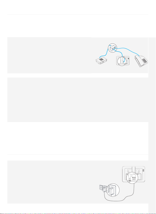
a. Using the PSTN transmitter (telephone landline)
Connect the smaller connector of the telephone cable
(supplied with your system) to the landline interface
in the battery compartment at the back of the panel.
Connect the other end of the telephone cable to the
signal output provided by your landline carrier or to the
phone connector of your ADSL box.
b. Using the GSM transmitter (SIM card)
Open the battery compartment at the back of the control panel and insert a SIM card in the
control panel.
Important
Before using the S4 Combo Secual in GSM mode, you need to purchase a SIM card that works
on the GSM network with 850 / 900 / 1800 / 1900 MHz frequency. We recommend you to
subscribe to a plan with unlimited texts and one hour of voice. For more information, please
contact your local reseller.
Important
Make sure the SIM card does not require any PIN code. For more information, please contact
your local reseller.
Turning your System On
1. Plug the AC adaptor to an AC socket.
2. Plug the output connector of the AC adaptor into the
adaptor interface in the battery compartment at the
back of the control panel.
3. Turn the power switch to "ON" (in the battery
compartment at the back of the control panel).
Accessories Safety and TroubleshootingQuick start-up Control Panel Operations SMS Operations
5
Page 6

Mount the Control Panel
Before mounting the control panel on the wall, make sure the reception of the GSM signal is sucient.
Fix the wall-mounting bracket on the wall with screws. Wedge the panel on the bracket, make
sure they t well.
First Operations
Select GSM / PSTN Mode
Refer to the instructions page 12 to deactivate the mode you do not want to use.
GSM mode only (SIM card required, sold separately): set "LINECUT ALARM" to "OFF"
PSTN mode only (connection to your telephone landline required): set "GSM FAIL TIP" to "OFF"
By default, both GSM and PSTN are activated.
Store a phone number
To interact with the control panel by SMS, by phone call and/or from the app, at least one phone
number must be stored in the control panel. Please refer to the instructions on page 10 of this
manual.
Change the language
By default the language of the S4 control panel is set to English. If you wish to change the system
language, refer to the instructions on page 25 of this manual. "System language" refers to the
language of the SMS you receive from the control panel, and the menu of the LCD display.
Arm / Disarm the System
The alarm system can be armed or disarmed on the control panel, by SMS, by App and by phone call.
On the control panel: Refer to the instructions on page 9 of this manual.
By RFID tag (disarm only): swipe the RFID tag in front of the RFID reader of the control panel.
To start receiving SMS notications when the system is disarmed by RFID tag, you must store an SMS
number and rename the RFID tags as explained respectively on page 21 and page 22 of this
manual (up to 4 RFID tags can be renamed). If you have stored several SMS numbers, only the rst
number stored will receive SMS notications when your system is disarmed by RFID tag.
By SMS (in GSM mode only):
To arm the system: send “1” by SMS to the number of the SIM card in the control panel.
To disarm the system: send “0” by SMS to the number of your system’s SIM card.
By app (in GSM mode only): Click on “Arm” in the app. The app is available for download on the
App Store and Google Play (more information on etiger.com).
6
Page 7

Register Wireless Accessories & RFID Tags
1. Type your admin code followed by “Enter” on the control panel to enter the setup menu.
2. Enter the Connection Mode by navigating through the menu:
"ACCESSORIES" --> "WIRELESS SENSORS" , "RFID TAG" or "REMOTE" --> "ADD A NEW"
When registering a detector, you will be asked to select the type of detector (Normal Sensor,
Home Sensor, Delay Sensor, 24 Hour Sensor). More information on page 10.
3. Trigger the accessory once within the next 15 seconds (for the RFID tag, swipe it in front of
the RFID reader of the control panel). You hear one beep: the registration is successful.
Default admin code is 123456. To change the admin code, refer to the instructions "Admin Code" on
page 12.
If the accessory has already been registered, the control panel will beep twice. The rst
accessory registered is assigned to zone 1, the second accessory registered is assigned to
zone 2, etc. Zones 1 to 9 can be renamed. Zones 10 to 50 cannot be renamed (refer to the
instructions on page 22 to learn how to rename zones).
Speed Dial
Press the Call button “ ” on the control panel for 3 seconds: the panel auto-dials the rst stored
phone number. Press the Call button “ ” to end the call.
Hands-free Phone Call from the Panel
Through PSTN
Press the Call button“
Through GSM
Press the Call button“
the Call button “
” on the control panel, type the phone number you wish to call and press “Enter”.
” on the control panel, type the phone number you wish to call and press
” again.
Accessories Safety and TroubleshootingQuick start-up Control Panel Operations SMS Operations
Hard Reset
Turn the control panel o. Press and hold the " " key while turning the control panel on.
Then enter "123456" on keyboard.
Settings will be restored to default values. Stored phone numbers and connected
accessories will be cleared.
7
Page 8
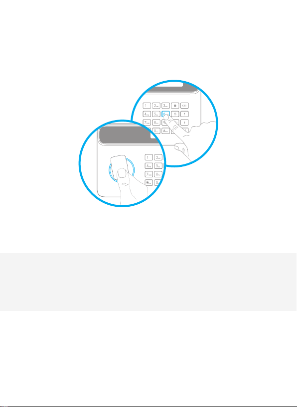
Control Panel Operations
Page 9

Arm the System
Press the Arm button " " on the control
panel. The control panel beeps once: the
system is armed.
Note
If the Entry / Exit Delay is activated, only the
Delay zone will be armed after the delay set
(refer to the instructions on page 12 of this
manual “Entry / Exit Delay”).
Disarm the System
Type your user code and press the Disarm
" on the control panel. The control
button "
panel beeps twice: the system is disarmed.
Default user code: 1234
Home Mode
Press the Stay button " " on the control
panel. The control panel beeps once: the
system is armed in Home Mode.
All the sensors assigned to the Normal zone
are armed. The sensors assigned to the
Home zone are disarmed.
For more information on zone setup, please
refer to the instructions on page 17 of this
manual.
Emergency Mode
Hold the “#
alarm is triggered immediately and the
siren rings out. At the same time, the control
panel dials the stored phone numbers.
” button for 3 seconds. The
SOS
Setup from the Control Panel
The control panel of your alarm system
features an LCD display that enables you to
navigate through the menu of the control
panel and set up your alarm system.
To enter the setting menu, type [your admin
code + Enter] on the control panel.
Default admin code: 123456
In the table on the next page, each column
represents a menu or a sub menu. Each
menu or submenu will be displayed on one
of the two lines of the LCD display. On the
LCD display, the current menu, submenu, or
setting is shown on the line at the bottom,
while the previous menu or submenu is
shown on the line at the top.
Navigate and select the setting you wish
to modify with the keys “ ” or “ ”, and enter
each menu or sub menu by pressing “Enter”.
How to use the keyboard
“ “ = delete
” = move forward
“
“ ” = move backward
“Enter” = select / conrm
“Esc” = back / previous step in the menu /
cancel
The tables on the next pages summarize
all the settings that can be accessed and
modied on the control panel.
Accessories Safety and TroubleshootingQuick start-up Control Panel Operations SMS Operations
9
9
Page 10

Main Menu Sub Menu 1 Sub Menu 2 Sub Menu 3 Comments Note
PHONE [1~5] IS:
PHONE NUMBERS
ACCESSORIES REMOTE
ACCESSORIES RFID TAG
ACCESSORIES
ACCESSORIES TEST MODE
SMS NUM [1~5] IS:
CMS NUM [1~2] IS:
ADD A NEW
DELETE ALL? 1=YES 0=NO
DELETE ONE ENTER 0130:
ADD A NEW PLS CONNECT
DELETE ALL? 1=YES 0=NO
DELETE ONE ENTER 0150
WIRELESS
SENSORS
ADD A NEW
DELETE ALL? 1=YES 0=NO
DELETE ONE ENTER 0150:
NORMAL SENSOR
HOME SENSOR
DELAY SENSOR
24 HOUR SENSOR
10
Page 11

Select the phone or SMS number you want to edit, type in the phone
number and conrm with the key "Enter". Use the key " " to clear.
5 phone numbers, 5 SMS numbers and 2 CMS numbers can be
stored in the control panel.
The LCD screen displays “PLS CONNECT 30”: press any button on
the remote control within the next 30 seconds (the countdown is
indicated on the screen after "PLS CONNECT", in seconds). You hear
one beep, the LCD screen displays “ADD OK! REMOTE [01~30]”: the
connection is successful.
Select the remote control you wish to delete.
The LCD screen displays “PLS CONNECT 30”: swipe the RFID tag
in front of the RFID reader on the control panel within the next
30 seconds (the countdown is indicated on the screen after "PLS
CONNECT", in seconds). You hear one beep, the LCD screen displays
“ADD OK! RFID [01~50]”, the connection is successful
Select the RFID tag you wish to delete
Select the sensor type you wish your sensor to be assigned to
(Normal Sensor, 24 Hour Sensor, Delay Sensor, or Home Sensor),
press “Enter” to conrm.
The LCD screen displays “PLS CONNECT 30”: trigger the detector
once within the next 30 seconds (the countdown is indicated on
the screen after "PLS CONNECT", in seconds). You hear one beep, the
LCD screen displays “ADD OK! SENSOR 01~50”, the connection is
successful.
Trigger the sensors you have previously connected to the control
panel. You hear 1 beep, the LCD screen displays the signals that have
been respectively sent by each sensor triggered. Make sure all the
sensors you have triggered are mentioned on the LCD screen. Press
“Esc” to exit the test mode.
If you want to set a CMS center phone
number, please refer to the instructions
on page 17 of this manual.
For more information on zone setup,
refer to the instructions on page 17.
This mode enables you to test if the sensors have been connected successfully
to the control panel.
Accessories Safety and TroubleshootingQuick start-up Control Panel Operations SMS Operations
11
Page 12

Main Menu Sub Menu 1 Sub Menu 2 Sub Menu 3 Comments Note
SYSTEM SETTINGS DATE AND TIME YYYYMMDD TIME e.g. 20140620 14H30
ENTRY DELAY 000300
SYSTEM SETTINGS ENTRY EXIT DELAY
EXIT DELAY 000300
AUTO ARM TIME <00:00>
SYSTEM SETTINGS AUTO ARM / DISARM
SYSTEM SETTINGS CONTROL BY PHONE ON / OFF
SYSTEM SETTINGS LINECUT ALARM ON / OFF
SYSTEM SETTINGS GSM FAIL TIP ON / OFF Notication of SIM/ GSM signal problem.
SYSTEM SETTINGS KEYPAD TONES ON / OFF
SYSTEM SETTINGS ACCESS CODE
AUTO DISARM TIME <00:00>
ON OR OFF?
ADMIN CODE 123456
USER CODE 1234
12
DURESS CODE 0000
OPEN DOOR CODE 8888
Page 13

This function can be used if you do not want to bring a remote
control or RFID tag with you. When the system is armed, you hear
one beep every second to remind you to leave. The beep rhythm
speeds up during the last 10 seconds. If an intruder is detected, the
alarm will be delayed accordingly.
Time is calculated in seconds. The Entry and Exit Delay can be set
from 0 to 300 seconds.
The entry and exit delay is only for sensors
connected as Delay Zone accessories (see
"Wireless" on page 10).
The Entry Delay gives you time to disarm
the system on the control panel without
triggering an alarm.
The Exit Delay gives you time to arm the
system on the control panel and leave
your home without triggering an alarm.
You can set up the system to arm and disarm automatically at a
dened time every day.
You can activate or deactivate the control of your system by phone
call. Activating the control by phone call enables you to arm and
disarm the system and monitor your home by phone call.
If the linecut alarm is on, the alarm will be triggered if your
telephone line is down. The rst SMS number stored receives a
notication by SMS (only in GSM mode).
Activate or deactivate the sound when typing on the keyboard of
the control panel.
Your admin code enables you to enter the setup menu.
Default admin code: 123456
Your user code enables you to disarm the system on the control
panel. The user code is the access code requested when you call
the control panel.
Default user code: 1234
In case of emergency, when you are requested to disarm the system by force, it is recommended to disarm your system with your
Duress Code. The panel will silently dial the stored phone numbers.
Default duress code: 0000
You can open electronic doors using this code. The door must be
wired to the [LOCK] interface on the back of the control panel.
Setting Auto Arm and Auto Disarm to
the exact same time will deactivate the
function.
See instructions on page 16 for more
information on the control of the system
by phone call.
Deactivate this function if you want
to use the alarm system in GSM mode
only.
Deactivate this function if you want to
use the alarm system in PSTN mode only.
It is recommended to change all codes
before using your system for the rst
time and to keep your codes secret
Accessories Safety and TroubleshootingQuick start-up Control Panel Operations SMS Operations
13
Page 14

Main Menu Sub Menu 1 Sub Menu 2 Sub Menu 3 Comments Note
SYSTEM SETTINGS RINGING TIMES <09>
SIREN SWITCH
WIRED SIREN
IN SIREN VOLUME 01 0=MUTE
SIREN ALERT TIME 3 MIN
SYSTEM SETTINGS SIREN SETUP
BUILTIN SIREN
WIRELESS SIREN
SYSTEM SETTINGS USER ID 4 DIGITS :0000
<ON OR OFF?>
ARM/DISARM TONE
<ON OR OFF?>
SIREN SWITCH
<ON OR OFF?>
ARM/DISARM TONE
<ON OR OFF?>
SIREN SWITCH
<ON OR OFF?>
ARM/DISARM TONE
<ON OR OFF?>
SYSTEM SETTINGS
SYSTEM SETTINGS CALL RECYCLE <09>
SYSTEM SETTINGS BACKLIGHT TIME 030 S Press “Enter” to adjust the time during which the LCD screen is lit. Backlight time can be set from 0 to 300 s
SYSTEM SETTINGS LANGUAGE Change the language of the system.
SYSTEM SETTINGS RESET
SYSTEM SETTINGS ABOUT ABOUT JUN 4 2014
HISTORY - - -
ARM UPLOAD ON / OFF More information on page 17 of this manual
DISARM UPLOAD ON / OFF More information on page 17 of this manual
14
Page 15

This function enables you to determine the number of times the control
panel will ring before taking your call (for control by phone call).
Siren ringing time is calculated in minutes, default setting is 3
minutes. If you set the ringing time to 0, the siren will not ring out.
More information on page 17 of this manual
When the alarm is triggered, the control panel dials the numbers
you have stored. If you do not disarm the system, the control
panel will call you again (up to 9 times). The “Call Recycle” function
enables you to dene the number of times the control panel
attempts to call you.
All system settings will be restored to default setting.
Stored phone numbers and connected accessories will be cleared.
Wired siren refers to a siren connected
to the control panel by wire.
Built-in siren refers to the siren featured
in the control panel.
Wireless siren refers to a siren
connected to the control panel by
radio-frequency.
This information is supplied by your CMS
center. After having stored the user ID, the
CMS center will be able to determine your
exact location according to your ID number.
Languages available may vary depending
on the version of your product.
Accessories Safety and TroubleshootingQuick start-up Control Panel Operations SMS Operations
Choose the event log you need to track, press “Enter”.
The control panel keeps in record the
latest 150 event logs.
15
Page 16

Control by Phone Call
This feature is available only after having enabled it from the control panel, as explained on page 12
of this manual.
Method 1
When an alarm has been triggered, the control panel dials the stored phone numbers. When you
pick up the phone, follow the voice instructions to control the panel from distance (refer to the
instructions in the table below).
Method 2
1. Dial the telephone number of your control panel (either the number of the SIM card in your
control panel or the number of the landline to which your panel is connected). After getting
through, the voice instructions will guide you to enter your access code.
2. Enter your access code (user code), followed by ”#”.
3. A voice gives you the options you can select.
4. Select the operations to control the panel (see instructions in the table below).
Note
The call will end automatically if you do not send any command within 30 seconds.
Table of commands for control by phone call
Command Function Comment
Press “1“ Arms the system Voice prompt “System armed”
Press “0“ Disarms the system Voice prompt “System disarmed”
“ Audio monitoring Press “ ” to extend the monitoring time
Press “
Press “3“ Phone call with control panel -
Press “6“ Turns the siren o -
Press “9“ Turns the siren on -
Press “#“ Exits control by phone call Hanging up also exits the control by phone call.
Note
In GSM mode, the audio monitoring is not limited in time.
In PSTN mode (connected to your landline), the audio monitoring is limited to 80 seconds. If you
wish to extend the time of audio monitoring, press the “
80 seconds.
” on your phone before the end of the
16
Page 17

Zone Setup of Accessories
Every detector can be assigned to 4 dierent categories of zones: Home Zone, Delay Zone,
Normal Zone and 24-H Zone. To assign a detector to a zone, follow the instructions on page
10 of this manual (the zone will be assigned at the time of connection of the accessory).
Normal zone
When the system is armed, if a sensor is triggered, the siren rings out. When the system is
disarmed, sensors do not trigger an alarm.
24h zone
Regardless the system is armed or disarmed, sensors assigned to the 24h zone can trigger an
alarm. It is recommended to assign smoke detectors, gas detectors and outdoor beam sensors to
the 24-H zone.
Delay zone
If you want to set up the entry and exit delay functions, corresponding sensors must be
assigned to the Delay zone. Once the delay time has been set up, the sensors will not trigger
the alarm during the delay set. Refer to the instructions “Entry and Exit Delay” on page 12 of
this manual. It is recommended to assign the Door / Window Contact to the Delay zone.
Home zone
When the system is armed in Home Mode, the sensors assigned to the Home zone do not
trigger an alarm. It is recommend to assign motion dectors to the Home zone so that you can
have your system armed in Home Mode when you are home and move inside your home without
triggering any alarm.
Connect to CMS Center
Ignore this step if you are not connected to a CMS center. I f you are connected to a CMS center,
the control panel will upload your contact ID to the CMS center automatically if an intrusion
is detected.
Accessories Safety and TroubleshootingQuick start-up Control Panel Operations SMS Operations
17
Page 18
...
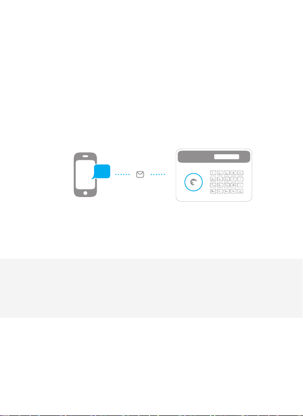
SMS Operations
Page 19
SMS Operations
IMPORTANT: BEFORE USING FOR THE FIRST TIME
INSERT A SIM CARD IN THE CONTROL PANEL BEFORE STARTING SMS OPERATIONS.
MAKE SURE THE SIM CARD DOES NOT REQUIRE ANY PIN CODE.
SAVE A SMS NUMBER IN THE CONTROL PANEL USING THE CONTROL PANEL.
Only stored numbers can control and congure the system.
Refer to the instructions page 10)
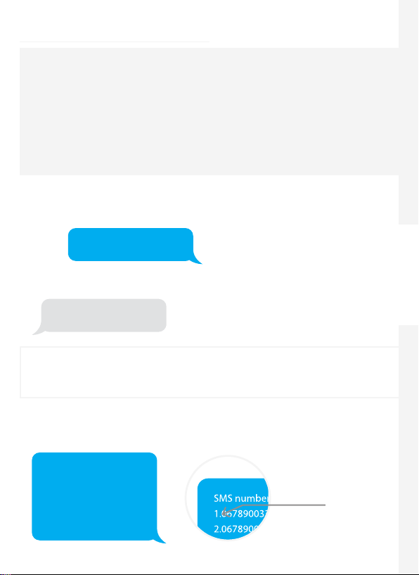
Each SMS operation dened in this user manual will be illustrated as follows:
You send:
SMS Command
The control panel replies:
Control panel’s reply
The system is in English by default. To change the system language, refer to the
instructions on page 25 of this manual.
Important
When replying to the control panel by SMS, make sure no space follows punctuation marks like
"." or ":". For examples, to store SMS numbers, your SMS must be formatted as follows:
The rst blue speech bubble is the SMS
command sent by the user.
The rst grey speech bubble is the reply sent
by the control panel.
The speech bubbles that follow are the
dialogue between the user and the control
panel (SMS sent by the user are in blue, SMS
sent by the control panel are in grey).
Accessories Safety and TroubleshootingQuick start-up Control Panel Operations SMS Operations
SMS numbers:
1.067890033
2.067890022
3.067890011
4.067890000
5.
No space after "1."
19
Page 20
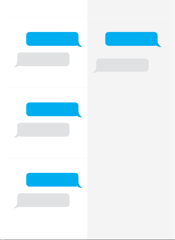
Disarm the System
Settings Enquiry
Send:
0
System disarmed.
Arm the System
Send:
1
System armed.
Home Mode
Send:
2
Send:
00
System:Disarmed
AC power:on
Note
The values indicated hereinabove will
change after having set up the system.
20
System in home mode.
Page 21

Store Phone Numbers
Send:
5
Phone numbers:
1.
2.
3.
4.
5.
Copy, paste, then edit
(case sensitive):
Phone numbers:
1. 067890033
2. 067890022
3. 067890011
4. 067890000
5.
Store Phone Numbers for SMS
Notications
Send:
6
SMS numbers:
1.
2.
3.
4.
5.
Copy, paste, then edit
(case sensitive):
SMS numbers:
1. 067890033
2. 067890022
3. 067890011
4. 067890000
5.
Accessories Safety and TroubleshootingQuick start-up Control Panel Operations SMS Operations
Ok
Ok
Note
The rst SMS number will receive SMS
notications when the system is disarmed
by RFID tag. To start receiving these
notications, you must rename the RFID
tags. Up to 4 RFID tags can be renamed.
Other tags will be attributed a number
based on the order of registration to the
control panel. Refer to the instructions on
page 10 to learn how to register an RFID
tag in the control panel.
21
Page 22

Rename Zones
Send "91~99". For example for zone 1, send:
91
SMS Alert for Accessory Low Battery
(available for two-way acessories such as
Motion Detectors)
For accessories assigned to zones that have
been renamed, an SMS will be sent under
the format “Zone name + low battery”.
Zones names:
1.
Copy, paste, then edit
(case sensitive):
Zones names:
1.Entrance door sensor
Ok
Note
Zones 1 to 9 can be renamed. The name of
the zone cannot consist of more than 30
Latin characters. Zones 10 to 50 cannot be
renamed.
Bedroom PIR low battery
For accessories assigned to zones that
have not been renamed, an SMS will be
sent under the format “Zone number + low
battery”.
Zone 10 low battery.
SMS Alert for Accessory Tamper
Alarm
(available for two-way acessories such as
Motion Detectors)
For accessories assigned to zones that have
been renamed, an SMS will be sent under
the format “Zone name + tamper alarm”.
Bedroom PIR tamper alarm.
For accessories assigned to zones that have
not been renamed, an SMS will be sent
under the format “Zone number + tamper
alarm”.
Zone 10 tamper alarm.
22
Page 23

Rename RFID Tag
Entry and Exit Delay Time
Send:
10
Rename RFID tags:
1.
2.
3.
4.
Copy, paste, then edit
(case sensitive):
Rename RFID tags:
1. Tom
2. Nurse
3. Nancy
4. David
Ok
Note
The rst SMS number will receive SMS
notications when the system is disarmed
by RFID tag. To start receiving these
notications, you must rename the RFID
tags. Up to 4 RFID tags can be renamed.
Other tags will be attributed a number
based on the order of registration to the
control panel. Refer to the instructions on
page 10 to learn how to register an RFID
tag in the control panel.
Send:
11
Entry delay time(0-300sec):0
Exit delay time(0-300sec):0
Copy, paste, then edit
(case sensitive):
Entry delay time(0-300sec):10
Exit delay time(0-300sec):20
Ok
Note
This function will only aect detectors
assigned to the Delay zone. Refer to the
instructions on "Wireless" on page 10 of this
manual to learn how to set up your sensor to
the Delay zone.
This function can be used if you do not want to
bring a remote control or a RFID tag with you.
When you arm the system, the system
will be armed after the delay set. When
you disarm the system, the system will be
disarmed after the delay set.
When arming the system, you hear one
beep every second to remind you to leave.
The beep rhythm speeds up during the last
10 seconds. If an intruder is detected, the
alarm will be delayed accordingly.
Accessories Safety and TroubleshootingQuick start-up Control Panel Operations SMS Operations
23
Page 24

Siren Volume and Ringing Time
Disarm Password
Send:
12
Siren volume(0=Mute,1=High):1
Siren ringing time(1-9min):5
Copy, paste, then edit
(case sensitive):
Siren volume(0=Mute,1=High):0
Siren ringing time(1-9min):1
Ok
Send:
13
Disarm password (4 digits):
1234
Copy, paste, then edit
(case sensitive):
Disarm password (4 digits):
8888
Ok
24
Page 25

Change System Language
Send the code corresponding to the
language you want to set. For example, for
English, send “0001”.
0001
Restore System to Factory
Settings by SMS
Send:
0000
Ok
Refer to the table below for the full list of
languages:
0001 English
0002 French
0003 Russian
0004 Danish
0005 Dutch
0006 Italian
0007 Swedish
Languages available may vary depending
on the version of your product.
0008 German
0009 Spanish
0010 Finnish
0011 Norwegian
0012 Arabic
0013 Farsi
Ok
The settings will be restored to default
values. Stored phone numbers and
connected accessories will not be deleted.
Note
Only stored numbers can send the SMS to
restore factory settings.
Accessories Safety and TroubleshootingQuick start-up Control Panel Operations SMS Operations
25
Page 26
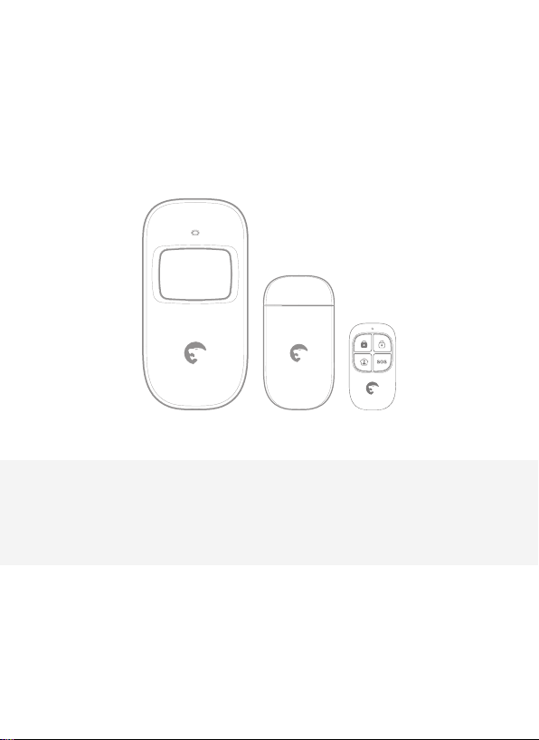
26
Accessories
Page 27
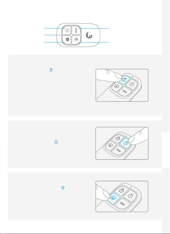
Wireless Remote Control
Disarm
LED indicator
Arm
Arm the system
Press the Arm button " " to arm the alarm
system. The LED indicator lights up (the
control panel beeps once). The system is
armed.
If an intruder is detected, the siren rings
out. (The siren turns o after 5 minutes as
per default settings.) In the meantime, the
system dials the stored phone numbers
automatically.
Disarm the system
Press the Disarm button " " to disarm the
alarm system. The LED indicator turns o
(the control panel beeps twice). The system
is disarmed.
Home Mode
Press the Home Mode button " " on the
remote control. The system state LED is on.
All the sensors in regular zones are armed
except those in the Home Mode zone.
The sensors in the Home Mode zone are
disarmed so that users can move inside
their home.
SOS
Home Mode
Accessories Safety and TroubleshootingQuick start-up Control Panel Operations SMS Operations
27
Page 28
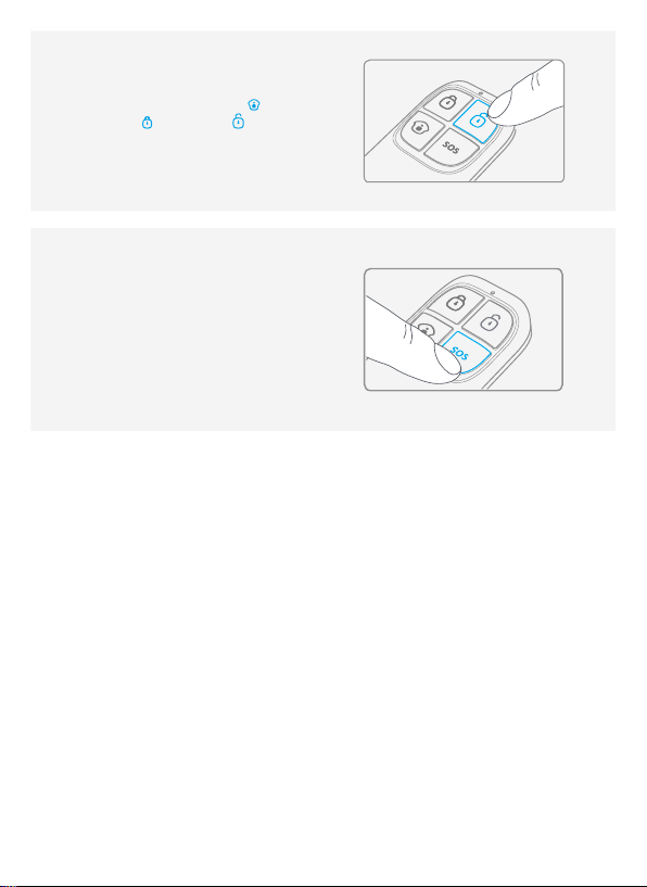
Mute Mode
Press the Home Mode button " " and
then the Arm " " or Disarm " " button
immediately after. Doing so, the control
panel does not beep when you arm or
disarm your system.
Emergency Mode
Regardless the status of the system, the alarm
is triggered when the SOS button "SOS" is
pressed on the remote control.
At the same time, the control panel sends a
notication by SMS ("RC-01 SOS", 01 being
the remote control's number) and dials the
pre-stored phone numbers.
Register in the control panel
Refer to the instructions in the table on page 10 of this manual "REMOTE".
To check if the registration is complete, refer to the instructions in the table on page 10
(“Test Mode”).
Specications
Power supply
DC 3V (CR2025 button battery x1)
Static current
≤10 uA
Operating current
≤7 mA
Transmission distance
≤ 80 m (in open area)
Radio-frequency:
315MHz (±75KHz)
28
Housing material
ABS plastic
Operating conditions
Temperature: -10°C ~ +55°C
Relative Humidity: ≤80%
(non-condensing)
Dimensions
57 x 31 x 11 mm
Page 29
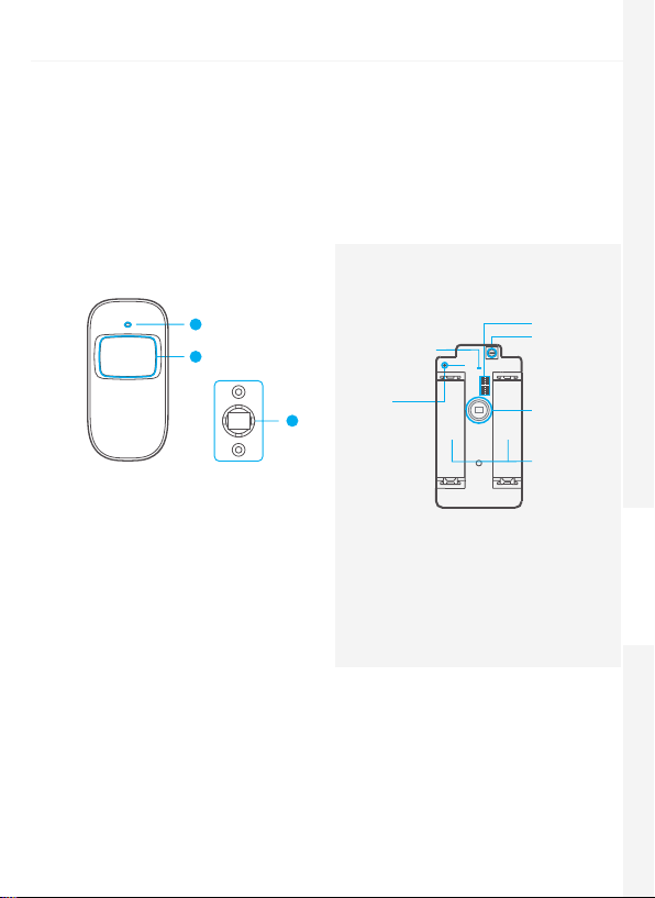
Wireless Motion Detector
Features
The ES-D1A is a high performance wireless motion detector boasting a digital dualcore fuzzy logic infrared control chip with intelligent analysis. This technology identies
interferences created by body motion and reduces the false alarm rate.
With automatic temperature compensation and anti-air turbulence technology, it easily
adapts to environmental changes.
Design
1. LED indicator
2. Detection window
3. Bracket
1
2
PCB Layout
LED working
indicator
Antenna
3
*Tamper switch
When the alarm system is armed, the tamper
switch will trigger the alarm if the case is
opened.
**Infrared sensor
Detects the infrared rays released by human
body motion. Do not touch the surface. Keep
the surface clean.
Alarm zone
setup
Tamper
switch*
Infrared
sensor**
AA 1.5V LR6
LED indications
Blinks continuously: self-testing
Blinks once: an intruder is detected
Blinks twice: self-testing is complete; entering working mode.
Blinks once every 3 seconds: under-voltage indication, the batteries must be replaced. (You
will be informed by SMS when the batteries are low if the motion detector is registered in the
control panel.)
Accessories Safety and TroubleshootingQuick start-up Control Panel Operations SMS Operations
29
Page 30

Usage
Open the case and remove the battery activation
strip. Self-testing will start for 30 seconds.
When the sensor is in operation, if it is triggered
more than twice within 3 minutes, it will switch
to standby mode to save power. If no movement
is detected within the next 3 minutes, the sensor
goes back to working mode.
Connect Button
Register in the control panel
Navigate through the menu of the control panel and reach "ADD A NEW" (Wireless Sensor).
Press the Connect button at the back of the motion sensor or trigger the sensor (by moving in
front of it) to register the detector in the control panel.
To check if the registration is complete, refer to the instructions in the table on page 10
"TEST MODE".
Installation
Avoid mounting the detector close to windows, air conditioner, heater, refrigerator, oven,
sunshine and places where the temperature changes fast or where the air stream ows
frequently.
If two detectors are installed in the same detection scope, adjust the location to avoid interferences
and false alarms.
Top
Fix the bracket on the wall with screws
and attach the detector to the bracket.
Adjust the bracket to change the
detection distance and angle. It is
recommended to mount the detector
2.2 m from the ground.
2.2 m
Ground
Boom
The detector is more sensitive to
cross movements than vertical
movements.
30
Top view
Side view
Page 31

Testing
A. After the installation, turn the detector on. After one minute of self-testing, press the test
button, walk in the scope of detection and watch the LED indicator to make sure the detector
is working.
B. The LED indicator blinks once when body movement is detected.
C. Adjust the detector angle to achieve the best detection performance.
Specications
Power supply
DC 3V (AA 1.5V LR6 Batteries x 2)
Static current
≤ 30uA
Alarm current
≤ 15 mA
Detection scope
8m / 110°
Transmission distance
≤ 80m (in open area)
Radio-frequency
315 MHz (±75 KHz)
Housing material
ABS plastic
Operating conditions
Temparature: -10°C~55°C
Relative humidity: ≤ 80% (non-condensing)
Detector dimensions (L x W x H)
107 x 53 x 32 mm
Bracket dimensions (L x W x H)
52 x 30 x 26.5 mm
Detection Scope
110°
Top view
0m 2m 4m 6m 8m
2m
0m
Side view
Accessories Safety and TroubleshootingQuick start-up Control Panel Operations SMS Operations
31
Page 32
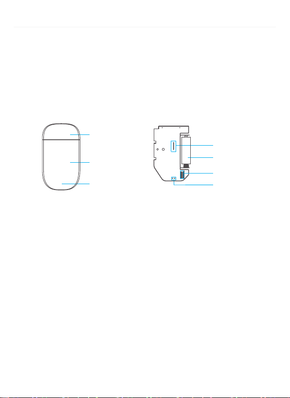
Wireless Door / Window Contact
Features
The ES-D3A is a Door / Window Contact that can be installed on doors, windows, and any other
objects that open and close. The sensor sends a signal to the control panel when the magnet
is separated from the transmitter.
Thanks to the tamper switch, any attempt to remove the cover of the Door / Window Contact
will trigger the alarm.
Design
Magnet
Transmitter
LED indicator
LED indications
Blinks once: the door or window is open and the transmitter sends a signal to the control
panel.
Blinks quickly: Low power indication, the batteries must be replaced.
PCB Layout
Tamper switch
A23 12V battery
Zone setting
LED working indicator
Register in the control panel
Navigate through the menu of the control panel and reach "ADD A NEW" (Wireless Sensor).
Then separate the magnet from the transmitter to register the detector in the control panel.
To check if the registration is complete, arm the system and separate the magnet from the
transmitter again by opening the door or window on which it is installed. If the siren rings
out, the registration is successful. Or refer to the instructions in the table on page 10 "TEST
MODE".
32
Page 33
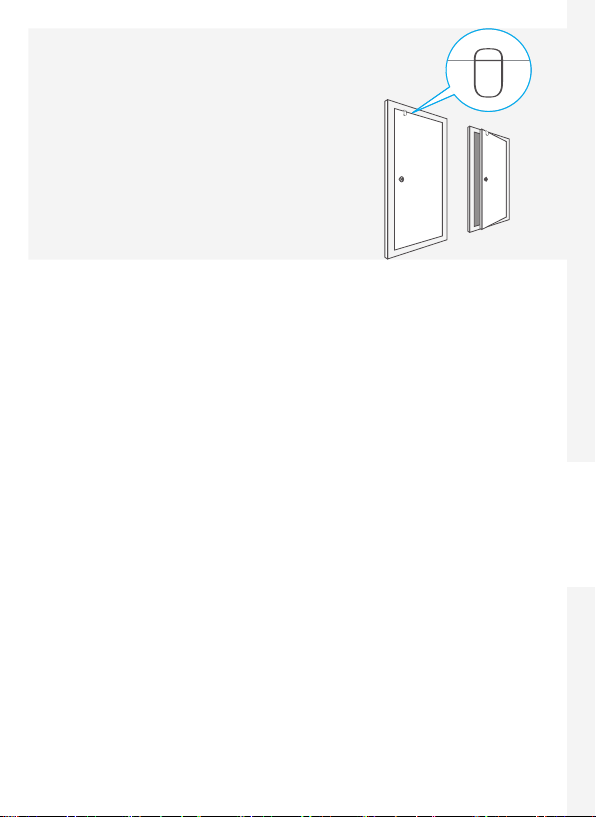
Installation
- Open the case and remove the battery activation strip.
- Mount the sensor on the door and the magnet on the
door frame.
- Make sure the magnet is placed above the transmitter.
- Mount the magnet max. 1 cm away from the transmitter
and secure the transmitter and magnet with doublesided tape or screws.
- Avoid mounting the sensor in areas with a large amount
of metal or electrical wiring such as a furnace or utility
room.
Specications
Power supply
DC 12V (A23 12V Battery x 1)
Static current
≤ 30 uA
Alarm current
≤ 15 mA
Transmitting distance
≤80 m (in open area)
Radio-frequency
315 MHz (±75 KHz)
Housing material
ABS plastic
Operating conditions
Temparature: -10°C~55°C
Relative humidity: ≤ 80% (non-condensing)
Transmitter dimensions (LxWxH)
60 x 45 x 18 mm
Magnet dimensions (LxWxH)
45 x 19 x 17.5 mm
Accessories Safety and TroubleshootingQuick start-up Control Panel Operations SMS Operations
33
Page 34

RFID Tag
Features
The RFID tag enables you to disarm your system or unlock electronic door locks.
Register in the control panel
Refer to the instructions in the table page 10 of this manual (“RFID TAG”).
Specications
Dimensions
45 x 30 x 7 mm
Register an Additional eTiger Siren
The control panel of the S4 features a built-in 100 dB siren.
Your eTiger security systems supports additional indoor and/or outdoor sirens so to enable
you to extend your system according to your needs.
To register an additional eTiger siren, refer to the instructions provided in the manual that
comes with your siren.
For more information on sirens and accessories compatible with eTiger security systems, visit
our website etiger.com
34
Page 35

Troubleshooting and Safety Instructions
Page 36

FAQ
Issue Cause of malfunction Solution
The control panel is switched oOpen the battery compartment
No response following
interaction with the
control panel
Accessories cannot
connect to the control
panel
No response from the
control panel following
commands from the
remote control
RFID tag fails to disarm
the system
Impossible to access
settings from the
control panel
If you are experiencing issues that are not described in the FAQ above, visit etiger.com to
download the latest update of this user manual and for additional support.
Electricity grid failure Contact your electricity provider
Backup batteries are empty
The control panel is not in
Connection mode
Accessories have not been
triggered for connection
When attempting the
connection, the control panel
beeps twice
The remote control has
not been connected to the
control panel
Remote control is too far from
the control panel
RFID tag has not been
connected to the control
panel
You are not in the setup menu
of the LCD display
and turn the power on
Plug the AC adapter to an AC
socket
Make sure the control panel is in
Connexion mode
Make sure the accessory is
triggered so to send a signal to the
control panel
The accessory has already been
connected
Make sure you do not trigger any
other accessory when connecting
one accessory to the control panel
(e.g. do not stay in the detection
scope of a motion detector if it is
not the one you want to connect)
Follow the instructions in this
manual to connect the remote
control to the panel
Transmission distance of the
remote control: 80 m (in open area)
A signal repeater can be installed
to increase the transmission
distance
Follow the instructions in this
manual to connect the RFID tag to
the control panel
Enter your admin code followed by
“Enter“ to enter the setup menu
36
Page 37

Precautions
For a safer use of the product and to optimize the lifespan of the product, we recommend you
to follow the precautions below:
- The wireless accessories must be connected to the control panel.
- Low power voltage may aect transmission distance.
- Do not press the SOS key on the remote control if it is unnecessary to avoid disturbing
neighborhood.
- Check the system regularly to make sure the system works properly.
- The control panel is neither waterproof nor moisture-proof, install it in a shady, cool and dry
place.
- The case of the control panel is made of ABS plastic. Keep away from bright light for a longer
lifespan.
- The control panel is not explosion-proof. Keep away from re and ames.
- Install the control panel away from objects such as heater, air conditioner, microwave oven etc.
that generate heat or electromagnetic elds.
- Dispose of the batteries according to local regulations.
- Dismantling of this product must be done by professional personnel only.
Accessories Safety and TroubleshootingQuick start-up Control Panel Operations SMS Operations
37
Page 38

Standards
This product bears the selective sorting symbol for waste electrical and electronic equipment
(WEEE). This means that this product must be handled pursuant to European Directive
2002/96/EC in order to be recycled or dismantled to minimize its impact on the environment.
For further information, please contact your local or regional authorities.
Electronic products not included in the selective sorting process are potentially dangerous for
the environment and human health due to the presence of hazardous substances.
In compliance with European laws. This product is in compliance with the essential
requirements and other relevant provisions of Directive 1999/5/EC.
This product was designed and manufactured in compliance with Directive 2002/95/EC of
the European Parliament and of the Council on the restriction of use of certain hazardous
substances in electrical and electronic equipment (RoHS Directive - RoHS) and is deemed to
comply with the maximum concentration values set by the European Technical Adaptation
Committee (TAC).
Manufactured in China.
Images, illustrations and text are non-contractual. ETIGER and the ETIGER logo are registered
trademarks and the property of ETIGER. Copyright © 2014 ETIGER. All rights reserved.
38
Rue de la Loi, 25, 7100 La Louvière, Belgium
ETIGER EUROPE
S4-C-UM-EN20140820-1.3-P
Page 39

FCC Information and Copyright
This equipment has been tested and found to comply with the limits for a Class B digital device,
pursuant to part 15 of the FCC Rules.
These limits are designed to provide reasonable protection against harmful interference in a residential
installation. This equipment generates,
uses and can radiate radio frequency energy and, if not installed and used in accordance with the
instructions, may cause harmful interference
to radio communications. However, there is no guarantee that interference will not occur in a particular
installation. If this equipment does
cause harmful interference to radio or televisi on reception, which can be determined by turning the
equipment off and on, the user is
encouraged to try to correct the interference by one or more of the following measures:
—Reorient or relocate the receiving antenna.
—Increase the separation between the equipment and receiver.
—Connect the equipment into an outlet on a circuit different from that to which the receiver is
connected.
—Consult the dealer or an experienced radio/TV technician for help.
This device complies with part 15 of the FCC Rules. Operation is subject to the
following two conditions:
(1)This device may not cause harmful interference, and
(2) this device must accept any interference received, including interference that may
cause undesired operation.
changes or modifications not expressly approved by the party responsible for compliance could
void the user's authority to operate the equipment.
This equipment complies with FCC radiation exposure limits set forth for an uncontrolled
environment .This equipment should be installed and operated with minimum distance 20cm
between the radiator& your body. This transmitter must not be co-located or operating in
conjunction with any other antenna or transmitter.
Page 40

www.etiger.com
 Loading...