

ETen ECV-2302 Quick Installation Manual
10/100Base-Tx VDSL2 Long
Reach Ethernet Extender
Quick Installation Guide
Introduction
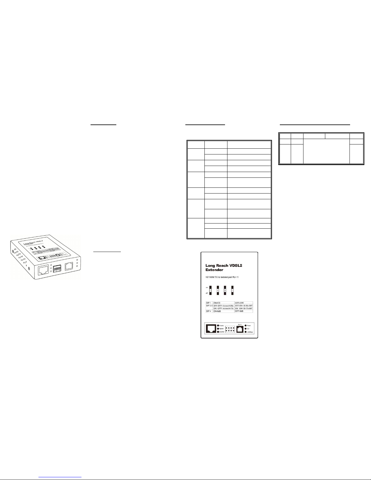
This device is a Long Reach Ethernet Extender
with one Ethernet port (on 1 RJ-45 connector) and
one VDSL2 port on 1 RJ-11 connector. This
extender is a bridge mode modem
accommodating well proven Ethernet and VDSL2
technologies to extend Ethernet over single-pair
phone line by using a VDSL2 signal. Up to 100/60
Mbps (or 90/90 Mbps with synchronous data rate)
transition bandwidth within 300m and 40/10 Mbps
for 1km long range connections that provides
ultra-high performance to the pervasive telephone
line network. Its plug-n-play solution minimum
installation time & cost by allowing video
streaming and data to share the same telephone
pair without interference.
With one DIP switches configuration, the Extender
including the CO (Central Office) site and CPE
(Customer Premise Equipment) site. It supports
high bandwidth VDSL2 over existing telephone
wires in the “last mile” from the ISP / Telecom /
Service provider’s fiber mode to the buildings and
customers’ home.
Key Features
One Ethernet Port (RJ-45)
One VDSL port (RJ-11)
Compliant with ITU-T G.993.2 (VDSL2)
Extending Ethernet over single-pair phone line
by using VDSL2 signal
Up to 90/90 Mbps transition bandwidth within
350m and up to 40Mbps for 1km long range
connections
Selectable DIP Switch for CO/CPE mode,
Annex A/B-17a/30a and SNR Control
Front Panel (LEDs)
LED Indicator
LED
Status
Description
Duplex
On
RJ 45 port full duplex
Off
RJ 45 port half duplex
Speed
On
RJ 45 connect at 100M
off
RJ 45 connect at 10M
Link/Act
On
RJ 45 port is link
Blinking
RJ 45 port Data is
transmitting or receiving
Power
On
Power is on.
Off
Power is off.
CO
On
Work as Master at Core
center
off
Work as CPE at Edge site
Nego
/Link /Act
Blinking
Negotiation
On
Link is connected
flash Blinking
Data Active
DIP Switches Mode Configuration
DIP 1 2 3 4
On
CO
OFF-OFF: Annex A-30a
OFF-ON: B-30a-997
ON-OFF: Annex A-17a
ON-ON: B-17a-997
6dB
Off
CPE
9dB
DIP 1 CPE or CO mode selection.
CO: Short of Central Office. After CO is
configured, the device acts as master
device of the VDSL connection.
CPE: Short of Customer Premises
Equipment. After CPE is configured, the
device acts as the terminal/client of the
VDSL Connection.
When connected the VDSL extenders,
one of the end must be configured to CO,
the other end must be configured to CPE.
DIP 2/3: Type of VDSL2 Frequency.
Default configuration is OFF-OFF, it
represents for Annex A-30a.
Please check with the service provider before
configured the DIP 2/3.
DIP 4: Signal Noise Rate selection.
Higher SNR means Less Noise, the data
transmitting quality is better. However, if
the device wants to remain better SNR,
the transmission rate may become lower.
For example, with the SNR 6dB, the
transmission performance is higher than
9db SNR. The DIP allows you to select
6dB or 9dB depends on your application.
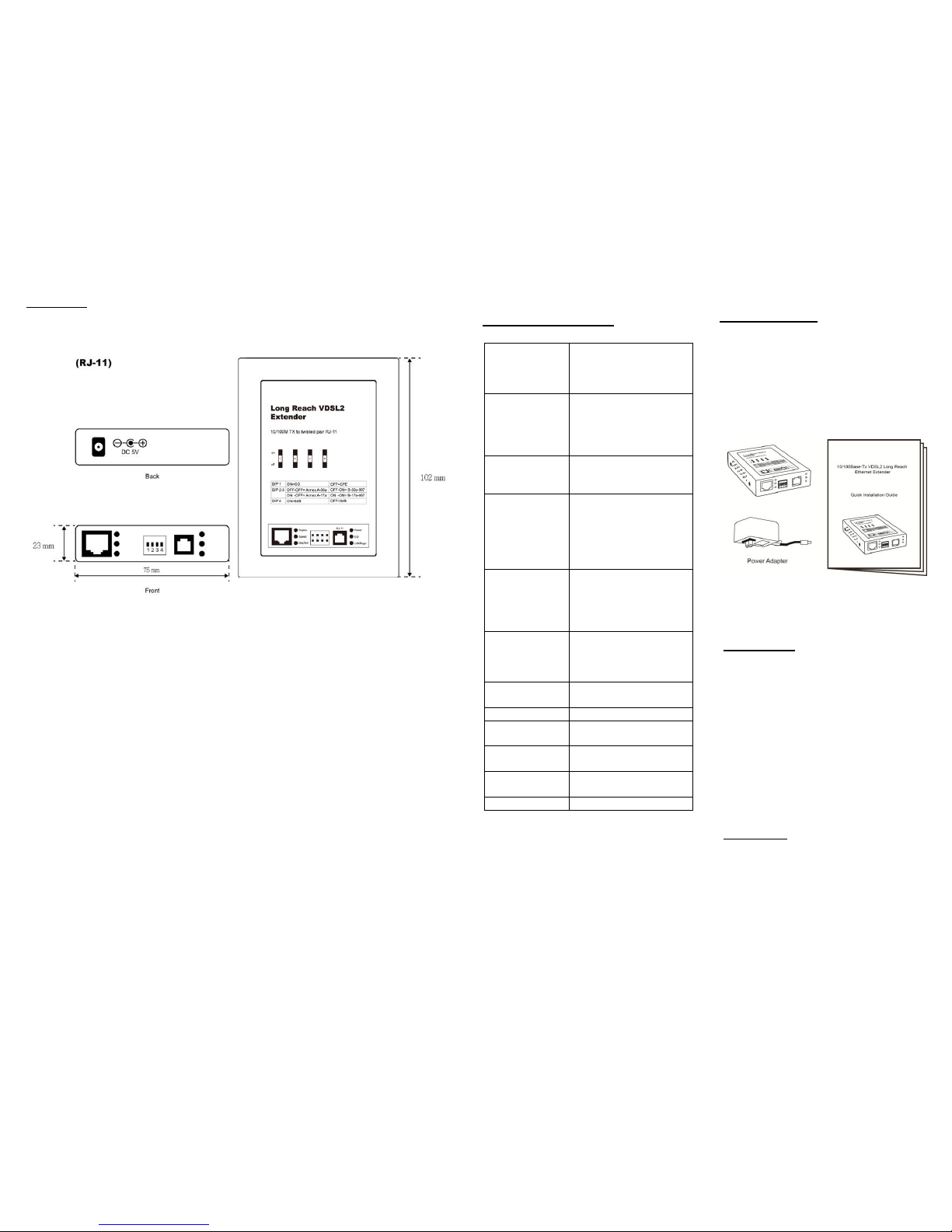
Mechanical
Technical Specifications
Standards
IEEE802.3 10Base-T
IEEE802.3u 100Base-TX
IEEE802.3x Full Duplex
ITU-T G.993.2 (VDSL2)
Interface
Ethernet: 10/100Base-TX
RJ-45 Connector,
Auto-MDI/MDI-X
RJ-11 female Phone Jack
DC Jack
Switching
MAC Address: 2K
Transmission Method:
Store and Forward
LED Indicators
Duplex
Speed
Link / Act
Power
Master
Link / Negotiation
DIP
DIP 1: CO/CPE mode
DIP 2-3: Annex A-30a,
B-30a-997, A-17a,
B-17a-997
DIP 4: SNR 6/9dB
Power Input
Adapter: 100~240VAC to
DC 12 Volt Output
Consumption : Max. 4.8W
@ 12V
Dimensions
102 × 75 × 23 mm
(L x W x H)
Weight
0.21 kg
Operating
Temperature
0 to 45℃
Storage
Temperature
-20 to 90℃
Humidity
10 to 90% RH
(non-condensing)
Certifications
FCC Class A, CE
Package Contents
Before you start to install this switch, please
verify your package that contains the
following items:
Two VDSL2 Long Reach Ethernet
Extenders
Two Power Adaptors
Quick Installation Guide
Note: If any of these items is found missing
or damaged, please contact your local
supplier for replacement.
FCC Warning
This device has been tested and found to
comply with limits for a Class A digital device
and pursuant to Part 15 of FCC Rules.
These limits are designed to provide a
reasonable protection against harmful
interference when the equipment is operated
in a commercial environment. This equipment
generates and radiates radio frequency
energy. If it’s not installed and used in
accordance with the user’s manual, it may
cause interference. In which case, users will
be required to correct interference at their own
expenses.
CE Warning
This is a Class A product. In a domestic
environment, this product may cause radio
interference in which case the user may be
required to take adequate measures.
 Loading...