

Page 1
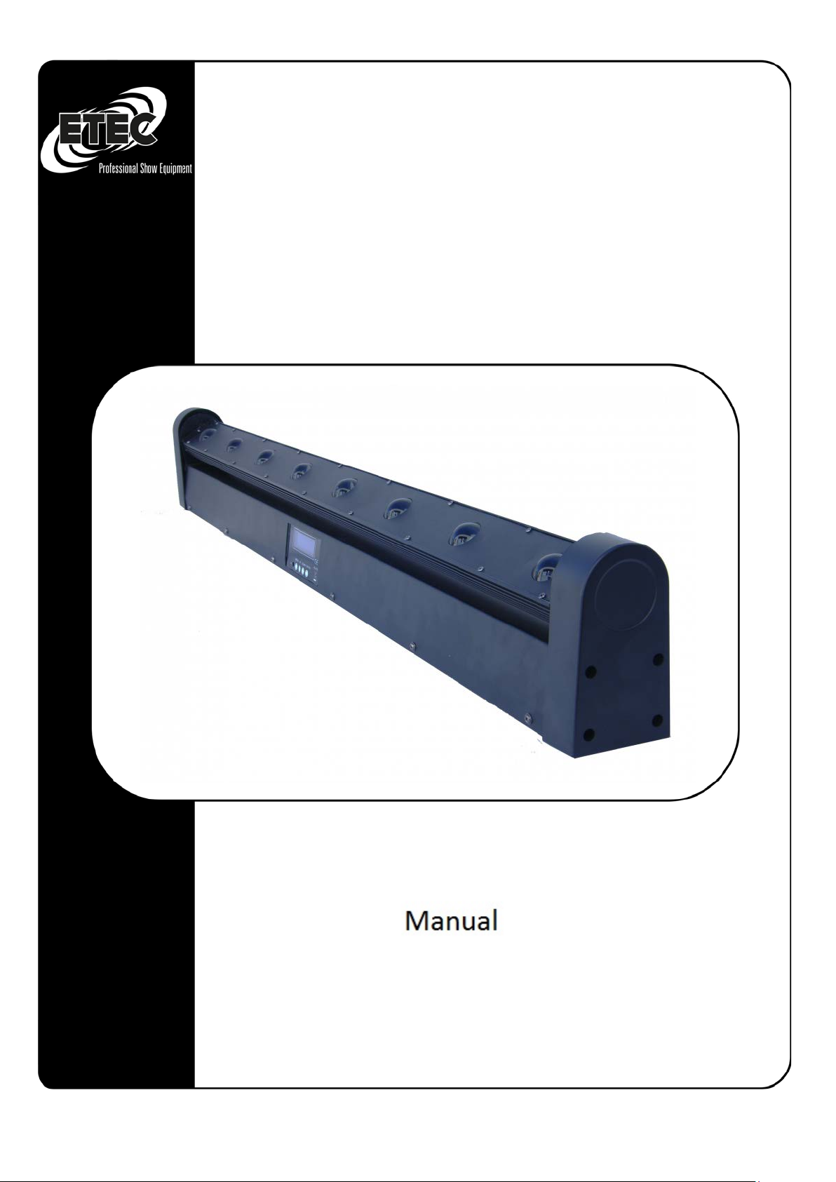
LED Roto Bar 8x10 Watt RGBW
Page 2

Table of Contents s
Introduction ............................................................................................................................................. 3
Important safety information.................................................................................................................. 5
Intended Use ........................................................................................................................................... 7
Disposal .................................................................................................................................................. 8
Maintenance ........................................................................................................................................... 8
Replace fuse ............................................................................................................................................ 9
Product description ................................................................................................................................. 9
Technical specifications ......................................................................................................................... 10
Functions and settings ........................................................................................................................... 10
Menu Display Overview ........................................................................................................................ 11
Menu explanation ................................................................................................................................. 11
DMX channel allocation ........................................................................................................................ 12
Installation / projector mounting .......................................................................................................... 15
Setting up a DMX connection ................................................................................................................ 17
Concluding note .................................................................................................................................... 17
Space for your notes ............................................................................................................................. 18
Page | 2
Page 3

Introduction
Congratulations!
You have acquired an excellent and innovative product from ETEC. In order to ensure the greatest
possible performance of the device, read this manual carefully and familiarize yourself with the most
important functions. This manual contains important information on the operation and maintenance
of this unit. Please keep this manual for future reference, together with the device.
Unpacking:
Please unpack the product immediately after receipt and check it for completeness and integrity. If
you notice any damage to the transport of one or more parts of the product or package, please notify
the seller immediately and collect the packaging material for later inspection. Keep the carton and all
related packaging materials. If the product needs to be returned, please make sure you return it in
the original packaging.
Provisional useful life of the LED headlamp:
The brightness of LEDs decreases with time. The main cause is HEAT because it speeds up the
process. When LEDs are placed very close together, they are exposed to a higher operating
temperature than when an ideal distance is maintained or operated under optimal conditions, ie
individually. For this reason, the useful life is significantly reduced when all color LEDs are operated
with maximum brightness. The service life achievable under normal operating conditions is
approximately between 40,000 and 50,000 hours. If the prolongation of the service life is of great
importance to you, you should ensure that the operating temperature is kept low. An air-conditioned
operating environment and the reduction of the overall luminous intensity can contribute to this.
Page | 3
Page 4
ATTENTION!
Disconnect the power cord before opening the housing!
ATTENTION! Be careful when handling this unit. In the case of
shock when you touch the cables!
Warnings
Protect the device from rain and moisture!
PLEASE READ THESE INSTRUCTIONS FOR YOUR SAFETY CAREFULLY,
BEFORE OPERATING THE UNIT FOR THE FIRST TIME!
Safety instructions:
All persons who install, operate and maintain this equipment must:
• Be qualified and
• Follow the instructions in this manual.
dangerous mains voltages, you could get a life-threatening electric
Before using the appliance for the first time, ensure that the product has not been damaged by
transport. If it is damaged, please contact the seller and do not use it. In order to ensure the perfect
condition and the safe handling, the safety instructions and warnings in this manual must be
observed.
Please note that we assume no liability for damages caused by manual changes. This device does not
contain any user-serviceable parts. Only carry out maintenance work by qualified technicians.
Page | 4
Page 5

Important safety information
The manufacturer is not liable for damage caused by the failure to observe this manual or
unauthorized modifications to this product.
• The power cord must never come into contact with other cables! Use the power cord and
all connections to the power supply.
• Do not remove the warnings and information labels from the product.
• The grounding contact must never be tampered.
• Make sure that no cables are around.
• Do not insert objects into the ventilation slots.
• Never connect this unit to another dimmer pack.
• Do not open or modify the unit.
• Never use the appliance during a thunderstorm. In the event of a thunderstorm, unplug the
power cord immediately.
• Do not turn the unit on and off at short intervals as this will reduce the lifetime of the unit.
• Do not expose the unit to shocks. Do not use excessive force when installing or using the
device.
• Use the product only in indoor areas and avoid contact with water or other liquids.
• Check that the housing is tightly closed and that all screws are tightened before using the
appliance.
• Do not place the product near open fires or flammable liquids or gases.
• Always allow at least 50cm clearance around the unit to ensure adequate ventilation.
• Always unplug the unit when not in use or when you want to clean it. Only hold the mains
cable at the provided area on the plug. Never unplug the cord from the wall outlet.
• Protect the product from extreme heat, moisture or dust.
• Make sure that the available mains voltage is not higher than indicated on the back of the
unit.
• Do not crush or damage the power cord. Check the unit and the power cord at regular
intervals for possible damage.
• If the connection cable is clearly damaged, it must be replaced.
• If the lens is clearly damaged, it must be replaced so that the functions of the unit are not
affected by cracks or scratches.
• Disconnect the appliance immediately from the power supply if it falls or becomes severely
damaged.
• Have the unit checked for safety by a qualified technician before using it again.
• Do not turn off the unit immediately after exposure to strong temperature fluctuations (eg
during transport). The resulting condensation could damage the unit. Do not turn the unit on
until room temperature is reached.
• Turn the power off immediately if it is not working properly. Pack the device carefully
(preferably in the original package) and send it to your dealer.
• Suitable for adult use only. The appliance must be placed out of the reach of children.
Never leave the connected device unattended.
• Only use replacement fuses of the same type and performance as the fuses already
contained.
• The user is responsible for the correct positioning and correct operation of the device. The
manufacturer is not liable for damages caused by incorrect use or incorrect installation.
• The unit falls under protection class I. Therefore it must be earthed with the yellow-green
cable.
Page | 5
Page 6

ATTENTION! EYE DAMAGE!
(Especially epileptics)!
• There may be too little smoke or odor during initial start-up. This is not unusual and does
not necessarily mean that the device is not working properly.
• Repairs, maintenance and electrical connections may only be carried out or handled by
qualified technicians.
Never look directly into the light source.
Page | 6
Page 7
International
Europe Cable
UK Cable
USA Cable
PIN L BROWN
RED
YELLOW/COPPER
PHASE
N
BLUE
BLACK
SILVER
ZERO
YELLOW-GREEN
GREEN
GREEN
GROUND
Intended Use
• This unit is not suitable for continuous operation. Maintaining regular operating breaks
increases the life of the unit.
• The minimum distance between the light source and the illuminated area is 0.5 meters
• The maximum ambient temperature for operation is ta = 45 ° C and must never be
exceeded.
• The relative humidity must not exceed 50% at an ambient temperature of 45 ° C.
• If the appliance is not used as described in this manual, it could be damaged and the
warranty void.
• Any improper use will lead to risks such as: Short circuits, burns,
• Electric shock, crashes, etc.
Your safety and the people you surround are in danger!
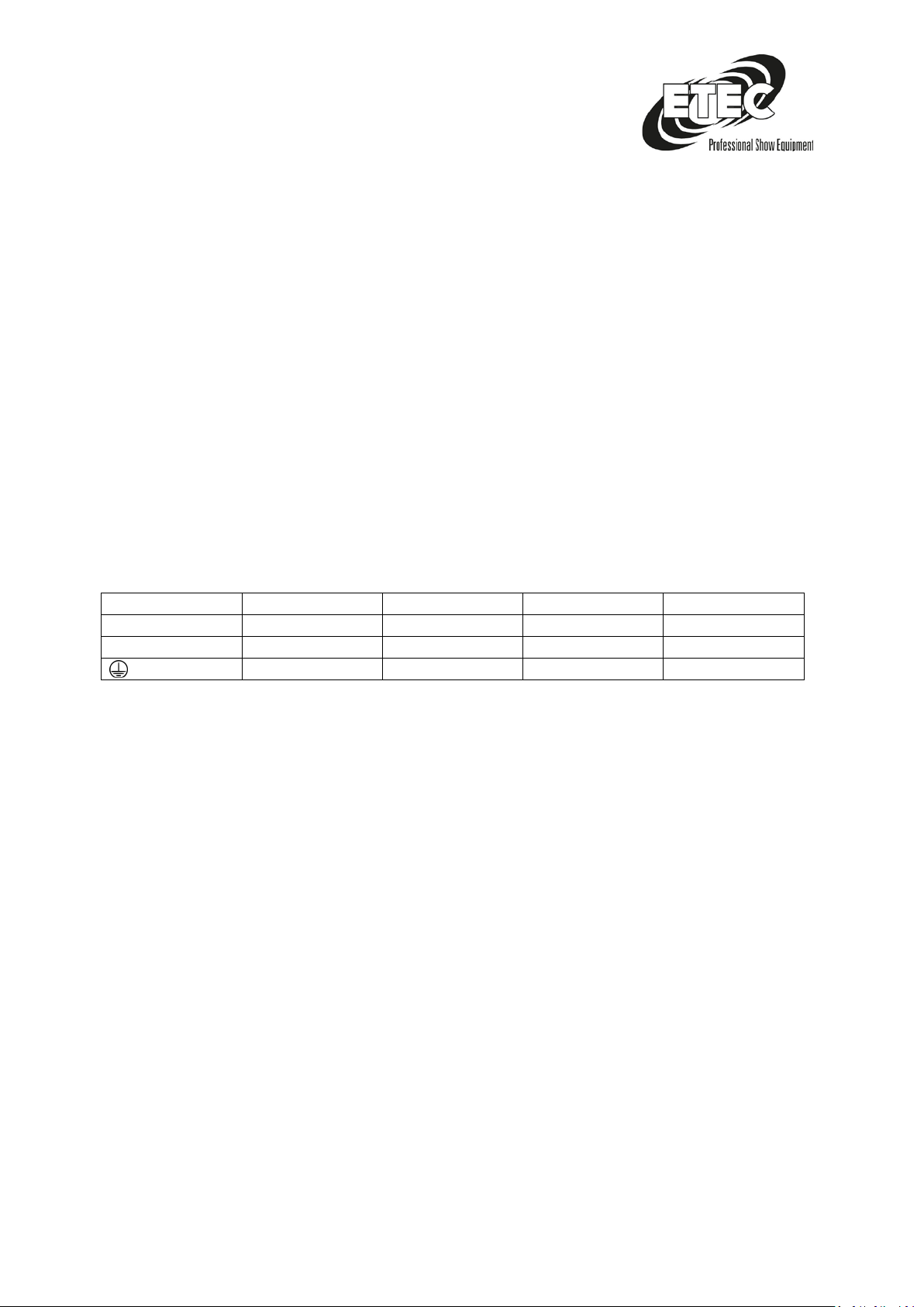
Power connections:
Connect the device to the power supply with the mains cable. Always ensure that the colored cables
are connected to the appropriate, correct locations.
Make sure that the device is always properly grounded!
Page | 7
Page 8

Disposal
Do not throw the appliance into normal household waste at the end of its useful life.
This product is subject to European Directive 2002/96 / EC.
• Dispose of the product via an approved disposal company or through your municipal waste
disposal facility.
• Observe the current regulations. If in doubt, contact your disposal facility.
• The packaging is certified by a dual system. Dispose of all packaging materials in
an environmentally friendly manner according to local regulations.
Maintenance
The device is almost maintenance-free. Nevertheless, the device should be cleaned regularly. If the
unit is not cleaned regularly, the light output of the unit will be considerably reduced over time.
Disconnect the unit from the mains and wipe it with a damp cloth. Never immerse the unit in any
liquid. Clean the unit with a soft cloth. Do not use alcohol or solvents. The connections should also be
cleaned regularly. Disconnect the device from the mains and wipe the connections with a cloth.
Ensure that all connections are completely dry before you connect or reconnect the device to other
devices.
The operator must ensure that all safety-relevant and mechanical devices are subjected to a
technical inspection test by qualified personnel after four years. The operator must ensure that all
safety-related and mechanical devices are inspected once a year by qualified personnel.
The following points must be considered during the inspection:
1. All screws used to install the product or parts of the product must be secured and not
corroded.
2. Neither the housing nor the fixtures or the places where the product is attached may be
deformed.
3. Mechanically moving components, such as axes, lenses, etc., must not have any wear marks.
4. Power cables must be undamaged and must not show any signs of material fatigue.
Page | 8
Page 9
1.
Replace fuse
Overvoltages, short circuits or unsuitable mains connections can cause a fuse to burn through. The
device does not work when the fuse is blown. If your device burns a backup, perform the following
steps.
1. Disconnect the mains plug.
2. Insert a flat screwdriver into the slot of the fuse cover. Lever the cover gently. The fuse now
comes to light.
3. Remove the old backup. If you look brown or milky, it is burned.
4. Insert the new fuse into the holder. Close the cover. Use only a fuse of the same type and the
same specifications. Observe the label with the technical data.
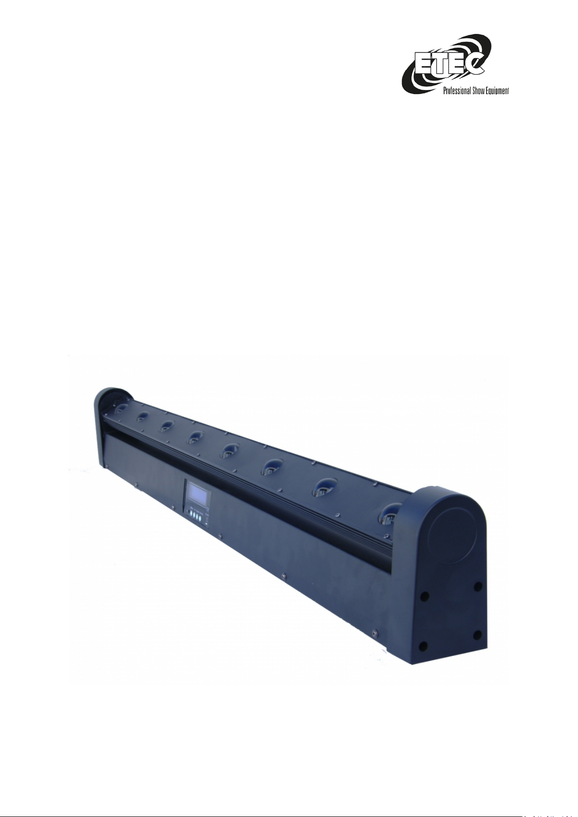
Product description
Page | 9
Page 10
Technical specifications
Power consumption: 180W
Power supply: 90 - 230V
Voltage frequency: 50 / 60Hz
Diodype: 4in1
Number of diodes: 8
Diode Power: 10W
Display: LCD matrix
Color: RGBW
Dimmer Linear: 0 - 100%
Number of DMX channels: 9/38
DMX standard: DMX 512
Control interface: 4 buttons
Operating modes: DMX512, automatic, music-controlled, manual, master / slave
DMX IN: XLR - 3-pin
DMX OUT: XLR - 3-pin
Protection class: IP20
Cooling: Fan
Height: [cm] 19
Width: [cm] 111
Depth: [cm] 13
Weight: [kg] 10.0
Functions and settings
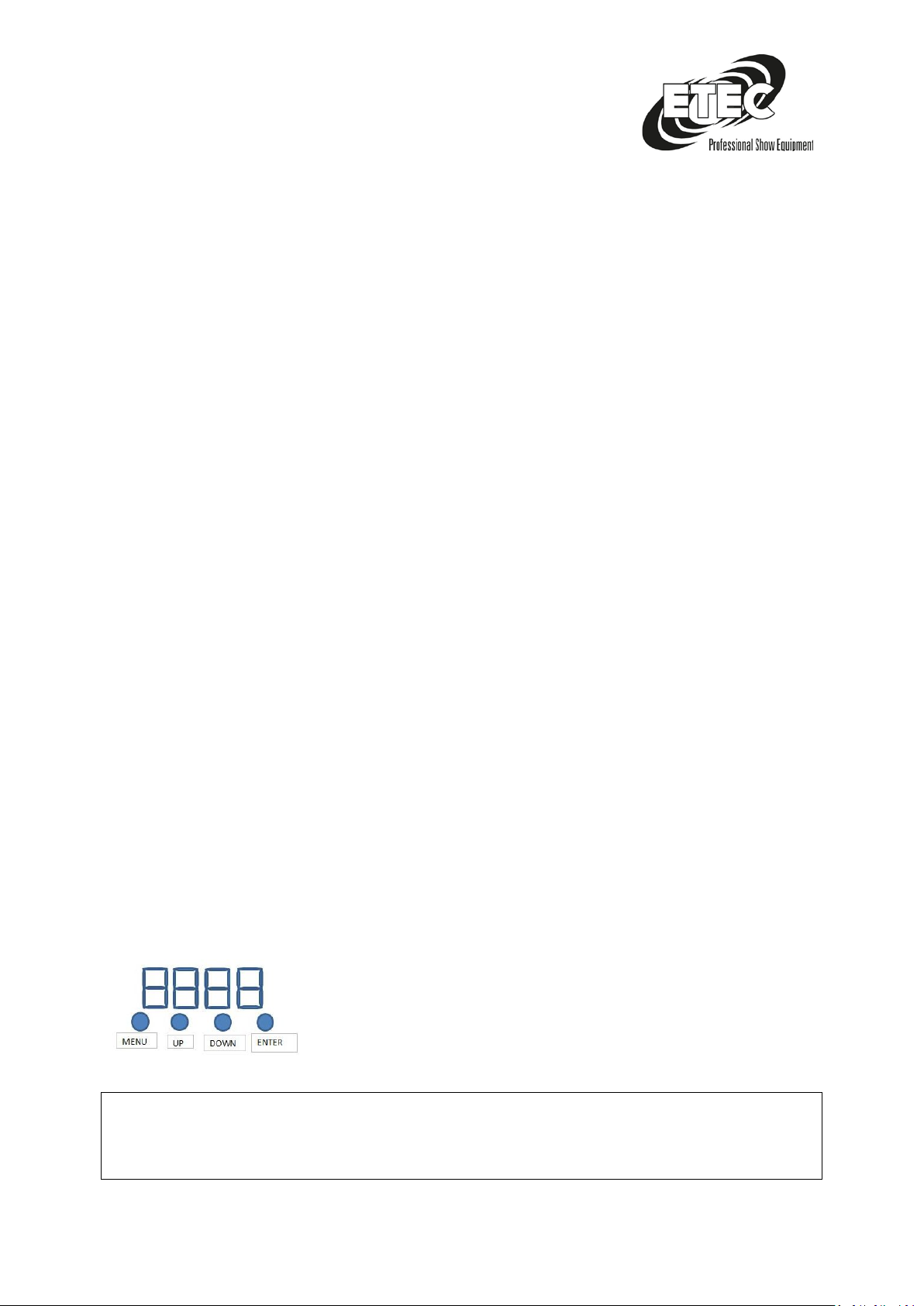
MENU: Function mode selection, such as DMX, Master / Slave, Auto, Sound Mode and Brightness
settings
DOWN/UP: Previous or Next function
Enter: Confirm and save the selection
Page | 10
Page 11
d001
001-512
9001
38 CH
9 CH
001-512
Au01-22
Au01
Effect 1
Au02
Effect 2
Au022
Effect 22
Soud
Sound control
SP01
01-08
Speed control
rPoF
OFF
motorforwardturnning
ON
Motor reversal
。。。
。。。。
M000
0-255
Motor deflection angle
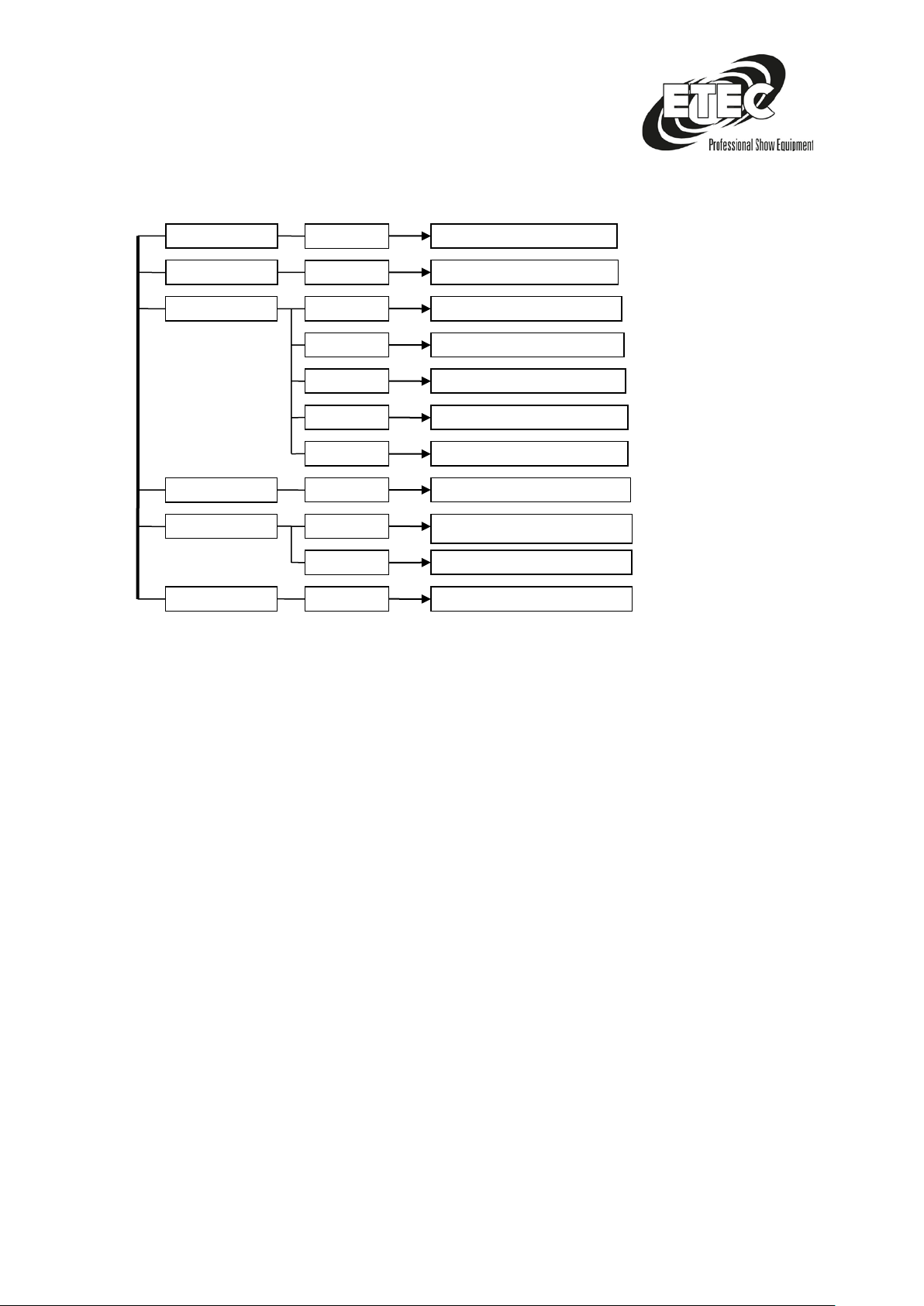
Menu Display Overview
Menu explanation
D001 DMX Channel modes with 38 DMX control channels
9001 DMX Channel modes with 9 DMX control channels
Au01-22 automatic programs 01 – 22
->Soud Sound control
SP01 Speed settings 01 -08
rPoF PAN invert
M000 Engine inclination angle
Page | 11
Page 12
1
Pan moving
0-255 Channel Function Description
2
Pan moving speed
0-255 Speed settings
3
Built-in effect
Internal programs
4
Built-in effect speed
Internal programs Speed settings
5
Master Dimmer
0-255 Master Dimmer 0-100%
6
RotDimmer
0-255 Red Dimmer 0-100%
7
GrünDimmer
0-255 Green Dimmer 0-100%
8
BlauDimmer
0-255 Blue Dimmer 0-100%
9
WeißDimmer
0-255 White Dimmer 0-100%
1
Pan moving
0-255 Movement of motors
2
Pan moving speed
0-255 Speed settings
Built-in effect
0-10
5-38 CH
11-22
Internal program1
21-31
Internal program2
32-42
Internal program3
43-53
Internal program4
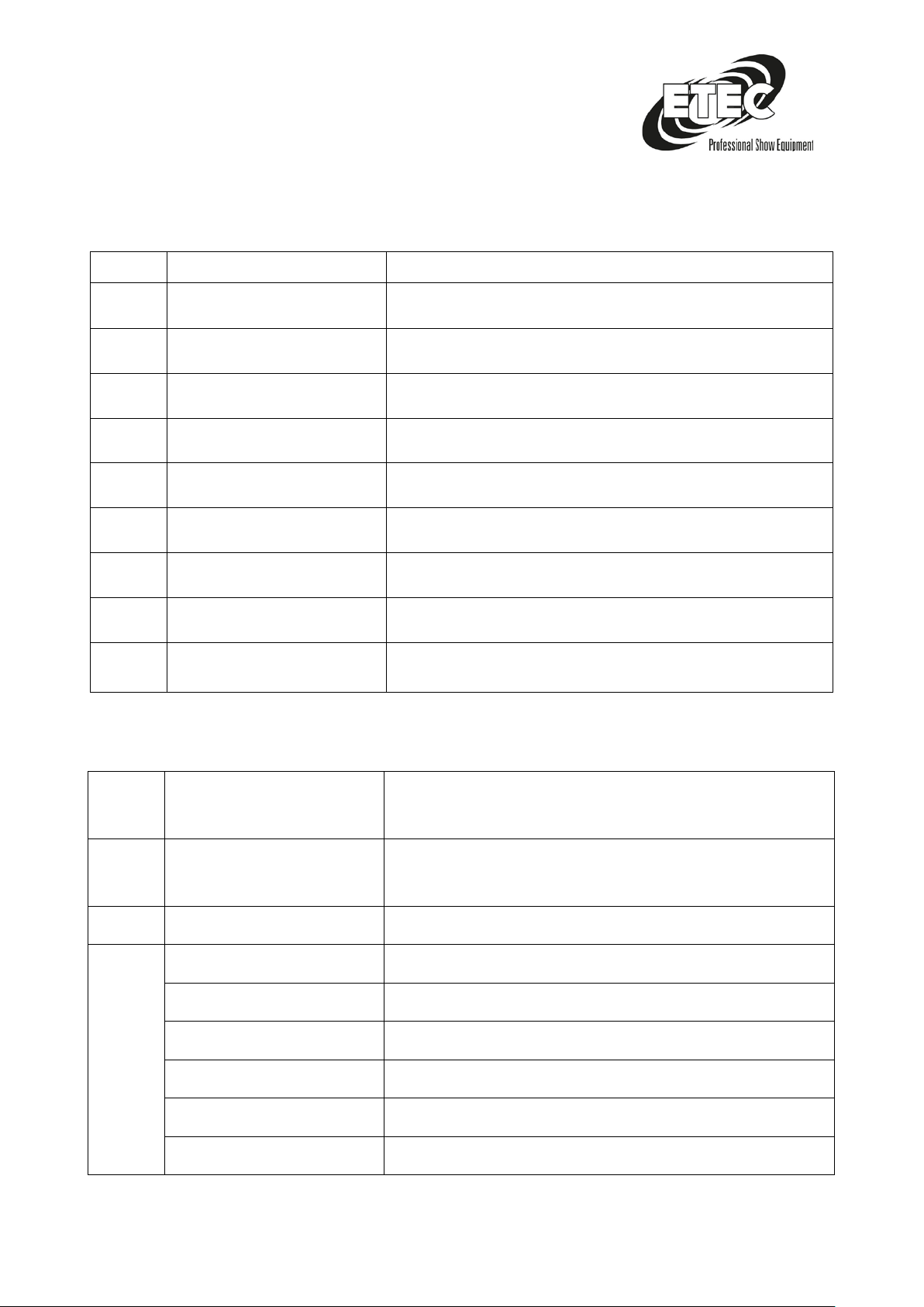
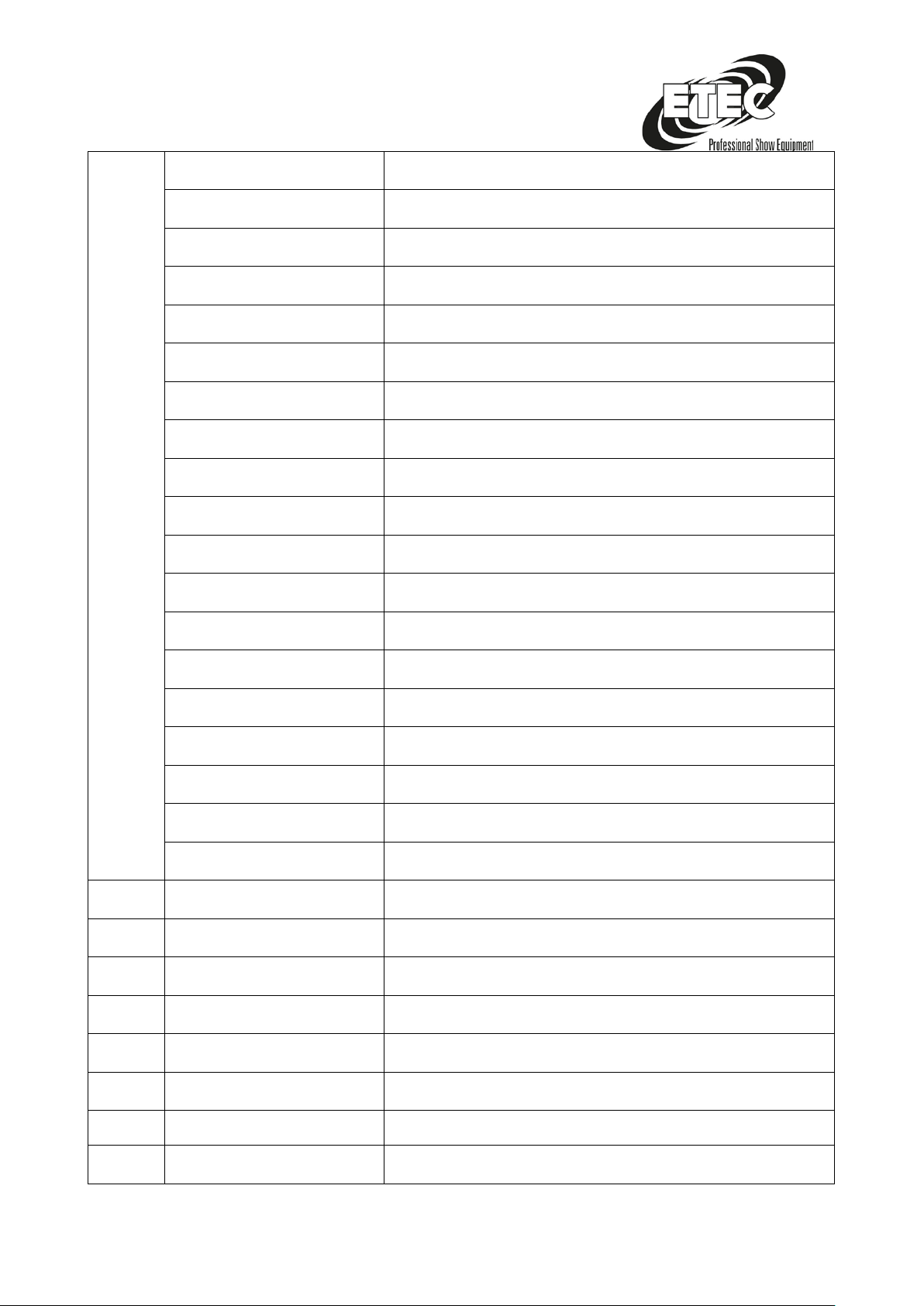
DMX channel allocation
9 Channels
Channel Function Description
38 Channels
Channel Function Description
3
Page | 12
Page 13
54-64
Internal program5
65-75
Internal program6
76-86
Internal program7
87-97
Internal program8
98-108
Internal program9
109-119
Internal program10
120-130
Internal program11
131-141
Internal program12
142-152
Internal program13
153-163
Internal program14
164-174
Internal program15
175-185
Internal program16
186-196
Internal program17
197-207
Internal program18
208-218
Internal program19
219-229
Internal program20
230-240
Internal program21
241-250
Internal program22
251-255
Sound control
4
Internal program Speed
Internal program Speed settings
5
Master Dimmer
0-255 Master Dimmer 0-100%
6
Strobe
6-255 Strobe setting, slow -> fast
7
BAR1 R Dimmer
0-255 Red Dimmer 0-100%
8
BAR1 G Dimmer
0-255 Green Dimmer 0-100%
9
BAR1 B Dimmer
0-255 Blue Dimmer 0-100%
10
BAR1 W Dimmer
0-255 White Dimmer 0-100%
11
BAR2 R Dimmer
0-255 Red Dimmer 0-100%
Page | 13
Page 14
12
BAR2 G Dimmer
0-255 Green Dimmer 0-100%
13
BAR2 B Dimmer
0-255 Blue Dimmer 0-100%
14
BAR2 W Dimmer
0-255 White Dimmer 0-100%
……
……
……
35
BAR8 R Dimmer
0-255 Red Dimmer 0-100%
36
BAR8 G Dimmer
0-255 Green Dimmer 0-100%
37
BAR8 B Dimmer
0-255 Blue Dimmer 0-100%
38
BAR8 W Dimmer
0-255 White Dimmer 0-100%
Page | 14
Page 15
CAUTION Danger to life!
Provisions of the BGV C1 and EN 60598-2-17!
Installation / projector mounting
During the installation, the
The suspension devices of the projector must be designed and dimensioned so that they can
withstand 10 times the payload for 1 hour without permanent harmful deformation.
The installation must always be carried out with a second independent suspension, For example, a
suitable fishing net. This second suspension must be designed and installed in such a way that no
part of the installation can fall in the event of a failure of the main suspension.
During the assembly, conversion and dismantling, the unnecessary stay in the area of movement
areas, lighting bridges, high-level workplaces and other hazardous areas is prohibited.
The contractor shall ensure that safety and technical equipment is inspected by experts prior to first
commissioning and after major modifications before commissioning.
The contractor has to ensure that safety engineering and mechanical engineering equipment is
inspected at least every four years by an expert in the scope of the acceptance test.
The contractor has to ensure that safety and mechanical equipment.
Method:
The projector should ideally be installed outside the area where people are sitting.
IMPORTANT! OVERHEAD ASSEMBLY REQUIRES A HIGH MEASUREMENT OF EXPERIENCE. This
includes (but is not limited to) calculations to define the load bearing capacity, the installation
material used and regular safety inspections of the material and the projector used. Never attempt
to perform the installation yourself if you do not have such a qualification; Plumber. Improper
installation may result in injury and / or damage to property.
The projector must be installed outside the hand area of people.
If the projector is to be suspended from the ceiling or high beams, etc., it is necessary to work with
the traverse system. The projector must never be mounted free-swinging in the room.
Danger: Projectors can cause serious injuries when falling! If you are in doubt about the security of a
possible installation, DO NOT install the projector!
Before mounting, make sure that the mounting surface can withstand at least 10 times the load on
the projector.
Page | 15
Page 16
CAUTION Risk of fire!
flammable materials (decoration, etc.) at a distance of at least 0.5 m.
CAUTION Danger to life!
When installing the appliance, please ensure that there are no easily
The device can be placed directly on the ground or installed in any possible position in the trussing
without changing its functional properties.
The projectorbase can be installed in two different ways.
Always secure the projector with an appropriate safety cable when installing the head (assembly
height> 100 cm).
Only safety ropes and quick coupling joints according to DIN 56927, Shackle according to DIN EN
1677-1 and BGV C1 Kettbiner may be used. The safety ropes, quick couplings, shackles and warp ties
must be adequately dimensioned and applied correctly on the basis of the most recent occupational
safety regulations (eg BGV C1, BGI 810-3).
Please note: For overhead mounting in public or commercial areas, a large number of regulations
must be observed which can only be reproduced here. The operator must independently seek and
comply with the applicable safety regulations!
The manufacturer is not liable for damages caused by improper installation and inadequate safety
precautions!
Hook the quick-release fastener into the provided eyelet eyelet on the bottom of the device. Route
the safety cable over the beam or a secure mounting point. Hook the end into the quick-release
fastener and tighten the locknut securely. The maximum drop distance must not exceed 20 cm. A
safety cable which has been subjected to a crash or is damaged is not allowed to be used as a safety
cable.
The device must be checked by an expert before commissioning!
Page | 16
Page 17
• Maximum recommended length of the DMX data transmission line: 100m
line: 30 devices
Setting up a DMX connection
DMX is a standardized transmission protocol that allows all DMX-compatible models of the various
manufacturers to be connected to one another and controlled by a single mixer. Free DMX data
transfer between different DMX devices are used.
The connection arrangement between the devices has no influence on the DMX addressing. For
example, DMX address 1 has been assigned to a device and it can be positioned at any point of the
DMX connection, at the beginning, at the end or anywhere in the middle.
Therefore the first device, which is controlled by a controller, can be the last one in a row at the
same time. When DMX address 1 has been assigned to a device, the DMX controller knows to which
address the data transfer set, regardless of the location of the DMX cable device.
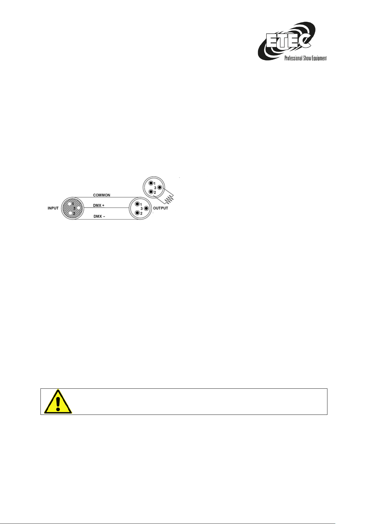
Resistance 120 ohms 1 / 4w between PIN 2 DMX -) and PIN 3 (DMX +) of the last headlight.
Attention: Avoid the contact between the general and the housing earthing of the spotlight. The
general grounding may cause a loop and your headlight could only work irregularly. Test the cables
with a resistance meter to check the correct polarity and to ensure the correct polarity.
Connect the headlights:
If you want to control light shows with one or more devices with a DMX-512 controller, or you want
to play synchronized shows with two or more devices in master / slave mode, you must use a serial
data transmission line. The total number of channels required by all devices determines the number
of devices that the data transmission line can support.
The devices connected to a serial data transmission line must be connected in series. According to
the standard EIA-485, no more than 30 devices should be connected to a data transmission line.
However, if you connect more than 30 devices to a serial data transfer line without using an optical
splitter, the quality of the DMX signal may be degraded.
• Maximum recommended number of headlights on a DMX data transmission
Concluding note
Technical and optical changes within the scope of product improvement are reserved - even without
prior notice.
Page | 17
Page 18

No liability shall be accepted for printing errors and resulting faulty operation. If in doubt, consult
your ETEC dealer!
Space for your notes
_________________________________________________________________________________
_________________________________________________________________________________
_________________________________________________________________________________
_________________________________________________________________________________
_________________________________________________________________________________
_________________________________________________________________________________
Importeur
Hansaring 138-142
48268 Greven
Fon: +49 (0) 25 71 - 80 5 40 42
Fax: +49 (0) 25 71 - 80 5 40 41
www.etec-professional.de
Page | 18
 Loading...