

Page 1
ETC® Setup Guide
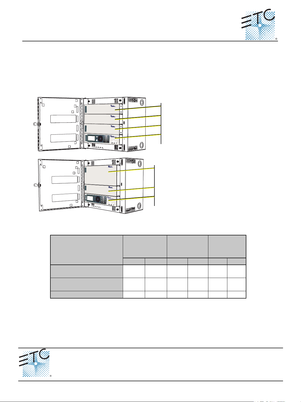
Blank module (ERn-BM)
Paradigm station repeater module (P-REP)
Paradigm architectural control processor (P-ACP)
Paradigm station power module (P-SPM)
Paradigm dual station repeater module (P-DREP)
Paradigm station power module (P-SPM)
Paradigm architectural control processor (P-ACP)
Paradigm Repeater Module Installation
The Paradigm station repeater (P-REP) module extends the system station bus length by 1,640
feet (500m) and adds support for up to 30 additional stations.
The Paradigm dual station repeater (P-DREP) module extends the system station bus length 3,280
feet (1,000m) through two separate Echelon segments, supporting 1,640 feet (500m) of additional
LinkPower station wire each, and adds support for up to 30 additional stations.
Both repeater module types may be utilized in the top module slots of the ERn4 rack enclosure.
The following table lists the recommended control wire types used in a typical Unison installation
and the maximum wire runs allowed.
Ethernet
(Cat5 /Belden
1583a)
Purpose
Link Power
(Belden 8471)
DMX
(Belden 9729)
Feet Meter Feet Meter Feet Meter
Total length of control wire
(without repeater module)
Maximum wire length (ERn
to station)
Maximum repeater distance
1640 500 1600 487 328 100
1313 400 1600 487 N/A N/A
1640 500 N/A N/A N/A N/A
Corporate Headquarters
London, UK
Rome, IT
Holzkirchen, DE
Hong Kong Rm 1801, 18/F, Tower 1 Phase 1, Enterprise Square, 9 Sheung Yuet Road, Kowloon Bay, Kowloon, Hong Kong Tel +852 2799 1220 Fax +852 2799 9325
Service:
Web:
7182M2210
Unit 26-28, Victoria Industrial Estate, Victoria Road, London W3 6UU, UK Tel +44 (0)20 8896 1000 Fax +44 (0)20 8896 2000
Via Ennio Quirino Visconti, 11, 00193 Rome, Italy Tel +39 (06) 32 111 683 Fax +44 (0) 20 8752 8486
(Americas) [email protected]
www.etcconnect.com
Rev A Released 08/2008
3031 Pleasant View Road, P.O. Box 620979, Middleton, Wisconsin 53562-0979 USA Tel +608 831 4116 Fax +608 836 1736
Ohmstrasse 3, 83607 Holzkirchen, Germany Tel +49 (80 24) 47 00-0 Fax +49 (80 24) 47 00-3 00
QSF 4.1.9.1
(UK) [email protected] (DE) [email protected]
Copyright © 2008 ETC. All Rights Reserved. Product information and specifications subject to change.
(Asia) [email protected]
Paradigm Repeater Module Setup Guide Page 1 of 4 Electronic Theatre Controls, Inc.
Page 2
ETC Setup Guide
Terminate LinkPower (LON®) Control Wiring
Unison control stations communicate with the Paradigm architectural control processor using the
LinkConnect station communication bus from the architectural control processor to the stations.
LinkConnect is based on Echelon
pair of wires (data+, data-).
Throughout this document, LinkConnect is referred to by the protocol it uses, LinkPower.
Termination is available for up to six home runs of LinkPower (LON) data runs utilizing Belden 8471
cable (or approved equal) plus one 14 AWG ESD drain wire when the data cable is not installed in
grounded metal conduit. LinkPower wiring is topology-free and polarity independent, you can install
your LinkPower data runs in any desired combination of bus, star, loop, and home. The total
combined length of LinkPower wire run cannot exceed 1,640 feet (500m), with a maximum distance
of 1,313 feet (400m) between any two un-repeated communicating devices. Without a repeater, no
device may be more than 1,313 feet (400m) away from the architectural control processor.
Standard LON interoperability requires that there should be a maximum of only one repeater
between any two LON devices. This means that only one repeater module, whether a Paradigm
station repeater module (P-REP) or a Paradigm dual station repeater module (P-DREP), may be
used per Paradigm architectural control processor (P-ACP). Each individual topology-free
LonWorks network can have no more than 62 LON stations with a repeater, station power module,
and Paradigm architectural control processor.
®
LonWorks® with LinkPower bidirectional protocol, and uses one
Paradigm Repeater Module
Note:
Note:
Step 1: Pull Belden 8471 (or approved equal) control wiring into the ERn4 enclosure.
Step 2: Strip 3/16” (4.8mm) of insulation from the ends of each wire pair.
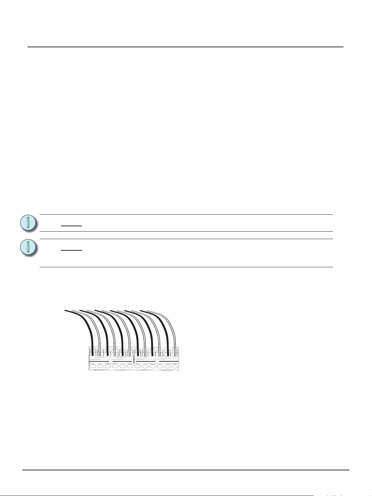
Step 3: Remove the LinkPower connector (labeled LON) from the I/O board
All low voltage control cables must run in separate conduit from power wires.
When utilizing a Paradigm station repeater module (P-REP) or Paradigm dual
station repeater module (P-DREP), terminate the affected LON segment(s) and
associated auxiliary power wiring to the top right I/O board in the ERn4 enclosure.
Notice the LinkPower/LON connector is labeled to
indicate that the connector is split between two LON
segments, allowing three station wire home runs per
segment. This is effective only when a Paradigm dual
station repeater module (P-DREP) is used. With the
standard Paradigm station repeater module (P-REP)
B A B A B A B A B A B A
1 2
all six station home runs connect to the single LON
control segment.
Paradigm Repeater Module Setup Guide Page 2 of 4 Electronic Theatre Controls, Inc.
Page 3
ETC Setup Guide
- + - + - + - + - +
Step 4: Loosen the terminal screws for the wire pairs you are terminating.
Step 5: Insert each white (typical) wire from the pairs into a “A” terminal on the connector and
tighten the screw(s) firmly to secure the wire into the terminal.
Step 6: Insert each black (typical) wire from the pairs into a “B” terminal on the connector and
tighten the screw firmly to secure the wire into the terminal.
Step 7: The 14 AWG ground wire can terminate to the ground bus located inside the ERn
enclosure.
Step 8: Replace the connector on the top I/O board.
Terminate Auxiliary Power
Auxiliary power is required when you are installing powered Unison control stations. ETC
recommends using two 16 AWG stranded wires for 24 Vdc auxiliary power to the control station(s).
Auxiliary power is topology-free. Maximum auxiliary voltage runs are dependant by the wire gauge
and the distribution of auxiliary load determined by each installation. The auxiliary supply is capable
of providing 36W (1.5A at 24Vdc).
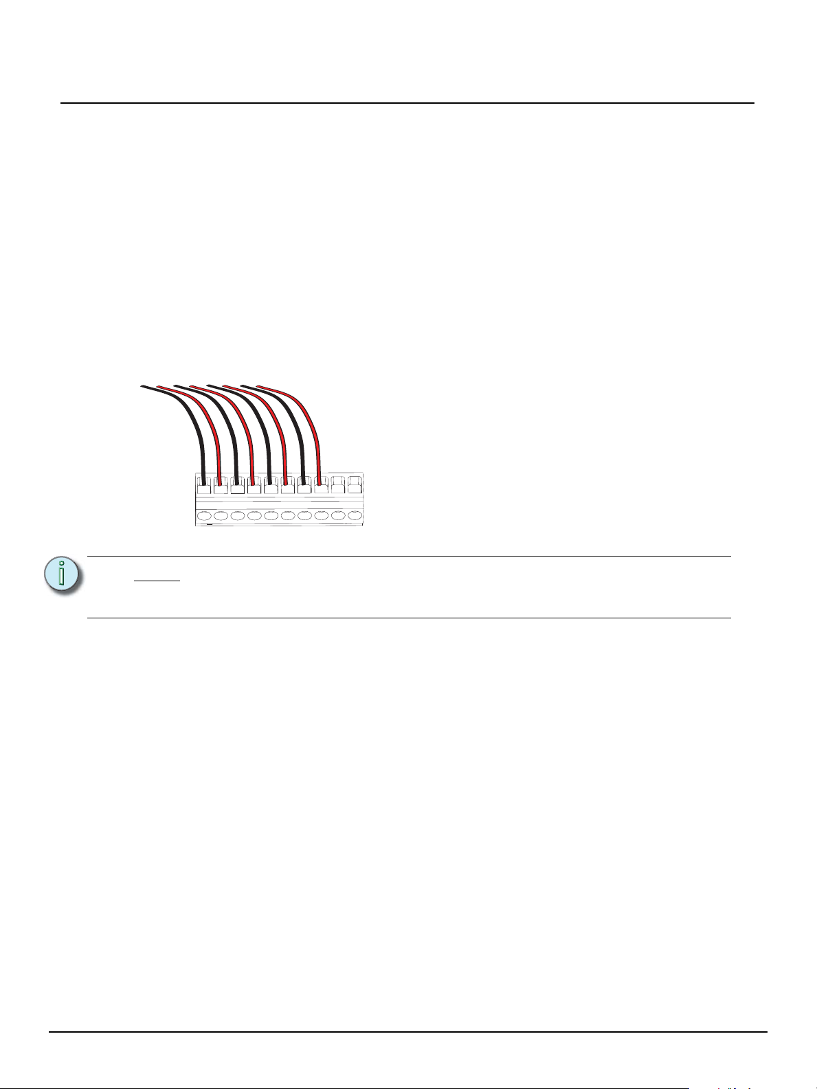
The auxiliary power connector (labeled Aux Power)
provides termination for up to 20 wires in the ten position
pluggable connector. Each terminal allows up to two 16
AWG wire and provides 24 Vdc power to Unison control
stations when used with the Paradigm ACP.
Paradigm Repeater Module
Note:
Step 1: Pull auxiliary control power wiring (typically 16 AWG red / black wire pair) into the
Step 2: Strip 3/16” (4.8mm) of insulation from the ends of each wire pair.
Step 3: Remove the auxiliary power connector from the I/O board.
Step 4: Loosen the terminal screws for the auxiliary wire pairs you are terminating.
Step 5: Insert the black (typical) auxiliary power wire from the pair into a “-” terminal on the
Step 6: Insert the red (typical) auxiliary power wire from the pair into a “+” terminal on the
Step 7: Replace the connector on the I/O board.
When utilizing a Paradigm station repeater module (P-REP) or Paradigm dual
station repeater module (P-DREP), terminate the affected LON segment(s) and
associated auxiliary power wiring to the top right I/O board in the ERn4 enclosure.
ERn4 enclosure.
connector and tighten the screw(s) to secure the wire into the terminal.
connectors and tighten the screw(s) to secure the wire into the terminal.
Paradigm Repeater Module Setup Guide Page 3 of 4 Electronic Theatre Controls, Inc.
Page 4

ETC Setup Guide
Status Indicators
When power is applied to the ERn enclosure, the Paradigm repeater module LEDs located on the
front panel illuminate, indicating the status of the auxiliary power, LinkPower control network, and
connected stations.
The Aux Power and LinkPower LEDs indicate in green when the Paradigm station power module is
connected properly and auxiliary power and LinkPower are present. When there is an unbalance in
LinkPower the fault indicators illuminate. This condition typically means that the station wiring has
a fault, however it could mean a connected device is having an issue. A qualified technician should
inspect the system wire and terminations first, then proceed to disconnecting devices to pinpoint
the fault and correct it. The power supply will update the fault indicators automatically when the fault
condition is cleared.
• If the NET A line has a fault (is shorted or has leakage to ground), the Fault + LED lights.
• If the NET B line has a fault (is shorted or has leakage to ground), the Fault - LED lights.
• If neither fault LED is illuminated the data connections are properly installed and the stations
are receiving the data and power required for operation.
Paradigm Repeater Module
Paradigm Repeater Module Setup Guide Page 4 of 4 Electronic Theatre Controls, Inc.
 Loading...