

Page 1
ETC® Setup Guide
C9
SmartLink™ Station Power Module S-SPM4
The SmartLink Station Power Module (kit part number 7024K1100) provides a SmartPack portable
dimmer pack with a centralized termination point of SmartLink, DMX, and an Emergency contact input.
The LinkPower Supply provides power for up to four SmartLink wall stations for remote preset and
sequence activation. Only one LinkPower supply per segment (system) allowed.
Power is provided from the SmartPack to the SmartLink Station Power Module via the RJ45-patch cable,
provided in the kit. Additional cable requirements may include:
Purpose Cable Type / Description Note
DMX Belden 9729 (recommended) or equivalent
SmartLink
Belden 8471 plus one 2,50mm
drain wire recommended (drain wire not required if
installed in grounded metal conduit).
Emergency
2 - 1,5mm
Installation
Connect Control Wiring
2
(16AWG), twisted
2
(14AWG) ESD
For use with wall stations. SmartLink is
FTT-10A topology-free and polarity independent.
Contact input for emergency lighting loads.
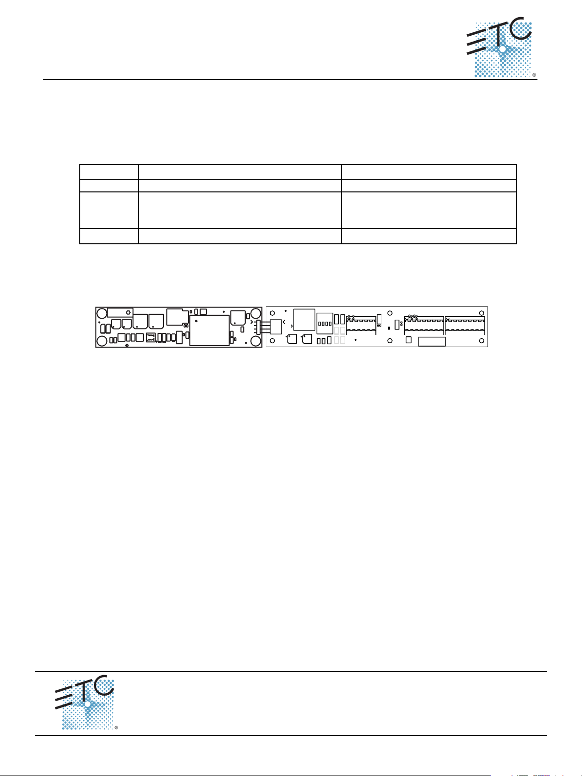
LinkPower Supply I/O board
ASSEMBLY
2
M1
I.D. LABEL
CR2CR1
M2
7021B4604B MADE IN USA
C3
C1
C2
R3 R4
R1
R2
L1
L2
2005 ETC, INC.
R8
CR7
VR1
C4
L3
C6
R7
T1
C5
CR4
CR3
CR5
R5
R6
CR6
GND
R11
R10
R9
EARTH
C8
CR8
J1
LINK
M3
POWER
J2
J1
M4
CONTROL
+
+
C1
C2
C3
PANIC/ LON
J3
LON1
LON2
DMX
NC
CR1C4CR2
34
21
S1
R3
R2
R1
NETB
NETA
CR3
CR4
NETB
M1
C5
PAN
COM
NETA
C7 C8
DMX IN
J4
J5
C6
L1
-
-
+
DMX
DMX
COM
DATA
ASSEMBLY
I.D. LABEL
CR5
DMX PASS-THRU
-
-
768
+
+
768
+
DMX
DMX
DATA
ISOCOM
DATA
7021B4602 REV.C
2005 ETC, INC.
MADE IN THE U.S.A.
DATA
C7
The six position pluggable screw terminal, labeled J3 Panic/LON, is provided as the termination point for
both Emergency and SmartLink control. The two remaining eight position pluggable screw terminals,
labeled J4 and J5, are for DMX In and DMX Pass-Thru. The RJ45 receptacle, labeled J2 Control, on the
I/O board is provided as the connection point between the SmartPack product and the SmartLink Station
Power Module.
Connect Emergency
Step 1: Strip 6,35mm (1/4”) of insulation from the ends of the two 1,5mm2 (16AWG) emergency wires.
Step 2: Remove the 6 position pluggable screw terminal from the I/O board.
Step 3: Twist the two wires together as close to the connector as possible.
Step 4: Insert one wire each into pins 5 and 6.
Step 5: Tighten the screw firmly for each wire.
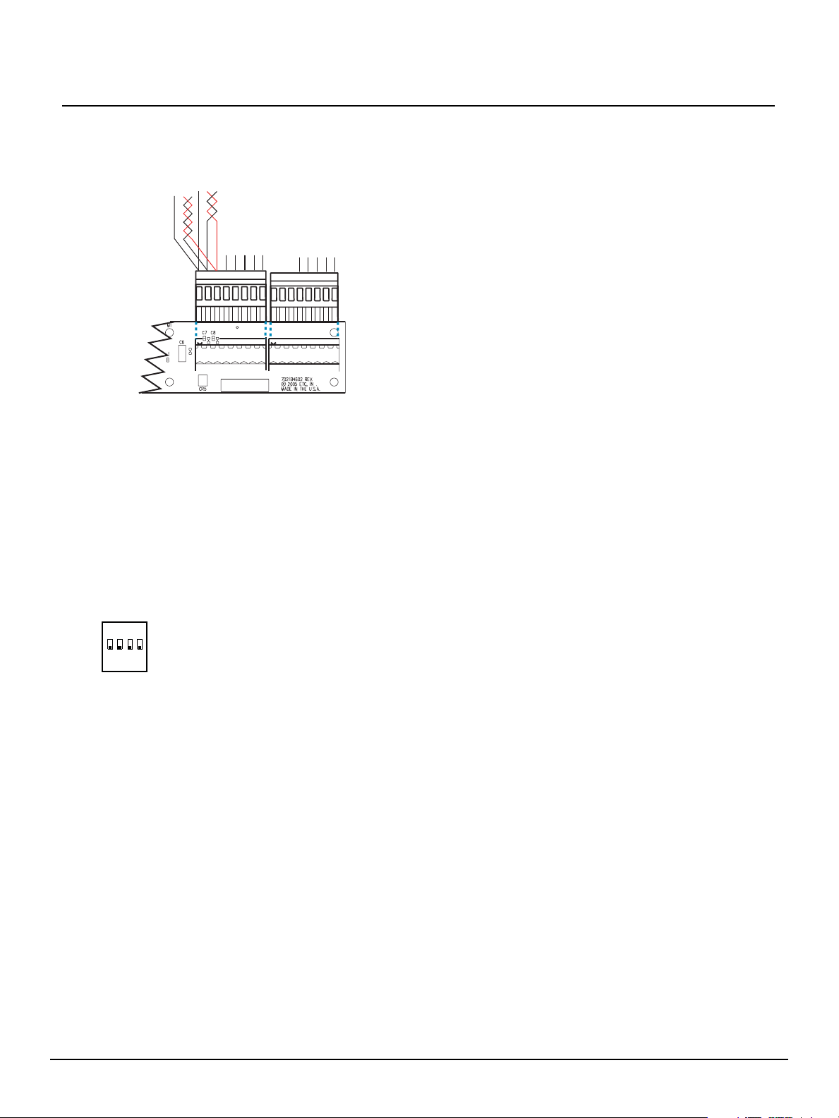
Connect SmartLink (LON)
Step 1: If pulling two Belden 8471 cables, label each pair with the data type and the run designation.
Step 2: Strip 6,35mm (1/4”) of insulation from the ends of the Belden 8471 wires.
Step 3: Insert the white wire from SL1 data run into pin 1 (Net B) terminal on the pluggable connector.
Step 4: Insert the associated SL1 black wire into pin 2 (Net A) terminal on the pluggable connector.
Step 5: Repeat steps 3 and 4 for the remaining data run (SL2) if required to the remaining pins 3 and
Step 6: Reinstall the 6 position pluggable connector to J3 on the I/O board.
Example SL1 and SL2.
Tighten the screw firmly.
Tighten the screw firmly.
4 terminal on the connector. Tighten the screw firmly for each wire.
Corporate Headquarters
London, UK
Rome, IT
Holzkirchen, DE
Hong Kong Room 605-606, Tower III Enterprise Square, 9 Sheung Yuet Road, Kowloon Bay, Kowloon, Hong Kong Tel +852 2799 1220 Fax +852 2799 9325
Service:
Web:
7024M2230
SmartLink™ Station Power Module S-SPM4 Page 1 of 2 Electronic Theatre Controls, Inc.
Unit 26-28, Victoria Industrial Estate, Victoria Road, London W3 6UU, UK Tel +44 (0)20 8896 1000 Fax +44 (0)20 8896 2000
Via Ennio Quirino Visconti, 11, 00193 Rome, Italy Tel +39 (06) 32 111 683 Fax +39 (06) 32 656 990
(Americas) service@etcconnect.com
www.etcconnect.com
Rev A Released 10/2005
3031 Pleasant View Road, P.O. Box 620979, Middleton, Wisconsin 53562-0979 USA Tel +608 831 4116 Fax +608 836 1736
Ohmstrasse 3, 83607 Holzkirchen, Germany Tel +49 (80 24) 47 00-0 Fax +49 (80 24) 47 00-3 00
Copyright © 2005 ETC. All Rights Reserved. Product information and specifications subject to change.
(UK) service@etceurope.com (DE) techserv-hoki@etcetcconnect.com.com
(Asia) service@etcasia.com
Page 2
ETC Setup Guide
SmartLink™ Station Power Module
Connect DMX
Prior to connecting DMX, follow the instructions for Belden 9729 cable preparation as defined on the
single sheet instructions packaged with the pluggable screw connector. A cable preparation kit for
installation of CAT5 cable is available, contact ETC for assistance.
(J4) DMX IN
(J5) DMX
PASS-THRU
As shown with Belden 9729 color code:
Pin 1 - Com
n/c
n/c
n/c
n/c
n/c
n/c
n/c
n/c
n/c
12345678
12345678
n/c
Pin 2 - DMX - (Black)
Pin 3 - DMX + (Red)
DMX In and Pass-Thru on the same pluggable screw
connector as shown.
COM
678
DMX+
DMX-
DATA-
DATA+
7021B5602
ISOCOM
678
DMX-
DMX+
DATA-
DATA+
B
Step 1: Using the 8 position pluggable screw connector provided in the cable preparation kit, connect
Shield (Com), DMX- and DMX+ as directed in the graphic above.
Step 2: DMX Pass-Thru using Belden 9729 can utilize the same pluggable screw connector as DMX
In. Connect Shield (Com), DMX- and DMX+ for DMX Pass-Thru as indicated in the graphic
above.
Connect the RJ45-Patch Cable
Connect one end of the RJ45-patch cable to receptacle J2 on the SmartLink Station Power Module and
the other end of the RJ45-patch cable to a SmartPack Portable dimmer pack.
Data Termination
• When using SmartLink with a LinkPower Supply installed in the segment (system), SmartLink is
automatically terminated at the LinkPower Supply. No further termination is required and LON
switches 1 and 2 should be set to Off.
• When using SmartLink without a LinkPower Supply installed in the segment (system), and
DMX
LON1
LON2
1234
OFF
SmartLink is utilized only for pack to pack synchronization, select one SmartLink enabled product
in the segment and set LON switches 1 and 2 On. All other SmartLink enabled products should set
LON switches 1 and 2 Off.
• When using DMX connected In and Thru the SmartLink Station Power Module and daisy-chained
to the RJ45 connectors on the rear of the SmartPack Portable dimmer pack, not via the XLR
connectors on the front of the SmartPack Portable dimmer pack, set switch 3 Off. You must provide
your own DMX termination at the last DMX device on the data run.
Connect ESD Ground
For installations with SmartLink data runs (Belden 8471) installed in grounded metal conduit there is
no requirement to run or terminate an additional ESD drain wire. For installations not installed in
grounded metal conduit, follow the instruction below for ESD termination.
Step 1: Locate the grounding lug on the right side of the I/O panel, next to the I/O board.
Step 2: Loosen, but do not remove, the set screw on the grounding lug.
2
Step 3: Strip 6,35mm (1/4”) of insulation from the ends of the 2,50mm
(14AWG) ESD drain wire(s) and
twist together.
Step 4: Insert the 2,50mm
2
(14AWG) wires into the grounding lug and secure.
Final Installation
Step 1: Locate the grounding pigtail and secure it to the rack at an available grounding point.
Step 2: Install the SmartLink Station Power Module into a standard 19” EIA rack and secure (hardware
not provided).
Reference the related SmartPack Portable documentation for setup and configuration details. Please
contact ETC Technical Services for assistance if needed.
SmartLink™ Station Power Module S-SPM4 Page 2 of 2 Electronic Theatre Controls, Inc.
 Loading...