

Page 1

Copyright © 2011. Electronic Theatre Controls, Inc.
All Rights reserved.
Product information and specifications subject to change.
Part Number:
7065M1200
Rev B
Released: 2011-11
User Manual
Production Dates: May 2011 - Present
Source Four XT HID Zoom 15° to 30°
Page 2

i
Table of Contents
ETC permits the reproduction of materials in this manual only for non-commercial purposes. All other rights are
reserved by ETC.
ETC intends this document, whether printed or electronic, to be provided in its entirety.
ETC is a registered trademark of Electronic Theatre Controls, Inc. in the United States and other countries.
Other product and company names mentioned herein may be trademarks and/or service marks of their respective
owners.
This product is protected by one or more of the following U.S. Patents: 6,016,038, 6,150,774, 6,788,011,
6,806,659, 6,683,423 and 7,023,543
Basic Assembly . . . . . . . . . . . . . . . . . . . . . . . . . . . . . . . . . . . . . . . . .1
Basic Information . . . . . . . . . . . . . . . . . . . . . . . . . . . . . . . . . . . . .1
Lamp and Ballast Information . . . . . . . . . . . . . . . . . . . . . . . . . . .2
Compliance Information. . . . . . . . . . . . . . . . . . . . . . . . . . . . . . . .2
Replacing the HID Lamp . . . . . . . . . . . . . . . . . . . . . . . . . . . . . . . . . .3
Installation . . . . . . . . . . . . . . . . . . . . . . . . . . . . . . . . . . . . . . . . . . . . .5
Electrical . . . . . . . . . . . . . . . . . . . . . . . . . . . . . . . . . . . . . . . . . . .5
Removing and Installing the Barrel . . . . . . . . . . . . . . . . . . . . . . .6
Adjustments . . . . . . . . . . . . . . . . . . . . . . . . . . . . . . . . . . . . . . . . . . . .8
Focusing the Beam . . . . . . . . . . . . . . . . . . . . . . . . . . . . . . . . . . .8
Shaping the Beam . . . . . . . . . . . . . . . . . . . . . . . . . . . . . . . . . . .10
Adjusting the Angle . . . . . . . . . . . . . . . . . . . . . . . . . . . . . . . . . .12
Cleaning the Lenses and Reflector . . . . . . . . . . . . . . . . . . . . . . . . .13
Cleaning Glass Lenses . . . . . . . . . . . . . . . . . . . . . . . . . . . . . . .13
Cleaning the reflector. . . . . . . . . . . . . . . . . . . . . . . . . . . . . . . . .14
Page 3
1
Basic Assembly
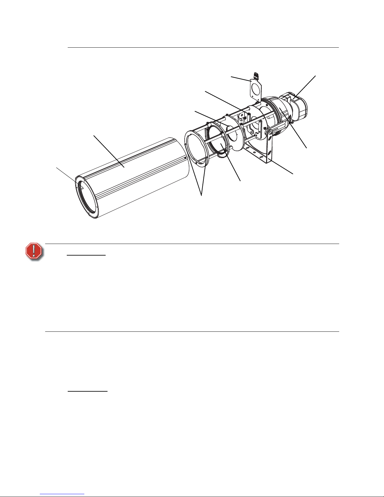
Figure-1 Components of the Source Four HID Zoom Fixture.
Basic Information
ETC’s Source Four XT HID Zoom is a Source Four spotlight for all-weather use. Powerful Source
Four optics, light output and energy savings in a sleek IP66-rated watertight and dustproof design.
XT features ETC’s Source Four Zoom 15° to 30° optical system plus our longlife 12,000-hour, 150W
HID lamp. Hang by yoke, place on ground, attach to poles and other structures.
Applications
WARNING:
Please note the following safety warnings before use:
Do not use this fixture with a damaged power lead. If the power lead
(cordset) is damaged, it must be replaced.
Do not mount the fixture on or near combustible surfaces.
Do not use this fixture if glass lens is deeply scratched or cracked. Damaged
lenses must be replaced.
Do not operate the fixture for long periods of time without the barrel
installed.
Remove foam packing from internal lenses before connecting power to your
fixture.
• Houses of worship • Retail store logos and patterns
• Theme parks • Outdoor performance venues (non-dimming)
• Museums
• Public sculptures
• Outdoor signage
Reflector
housing
Ballast
Pattern holder
Barrel
Yoke
Barrel locating
hole
Focus lens
and frame
Field lens
and frame
Pattern holder
slots
Locating pin
Page 4
2 Source Four XT HID Zoom User Manual
Lamp and Ballast Information
HID Lamps
Ballast
• Acceptable voltage is either 120V or 220V - 277V (±10%) 50/60 Hz only, depending
on the model purchased.
• 120V (Nominal) Ballast:
• 120V ±10%, 60Hz
• 1.5 Amps operating current
• 220V, 230V (50Hz), 240V, 277V (Nominal) Ballast:
• 277V ±10%, 60Hz
• 220V, 230V, 240V ±10%, 50Hz/60Hz
• 0.61 Amps operating current at 277V
• 0.69 Amps operating current at 230V
• 150 watt, high-power factor, fully encapsulated electronic ballast.
• Tilt-down ballast housing for lamp change, without disturbing focus.
Compliance Information
Complies with Low Voltage Directive and EMC Directive. Tested to Standards:
EN60598-1, EN60598-2-17, EN60922, EN55015, EN61000-3-2, EN61000-3-3,
EN61547.
CAUTION:
Do not use lamps other than the HID in Source Four XT fixtures. Use of lamps
other than HID will void UL/cUL safety compliance and your warranty.
CAUTION:
This fixture must be grounded.
CAUTION:
The fixture is sold for either 120V or 220V, 230V (50Hz), 240V, 277V to match the
power supply. Verify that the lamp and ballast voltage requirements matches your
power supply. Connecting the fixture to the wrong voltage voids the
warranty.
Ceramic Metal Halide
Part
number
Lamp code Watts Base Bulb
Initial
Lumens
Color temp. CRI
Average rated
life
RT157 CDM150/T6/830
150 G12 T6
14,000 3000°K 85 12,000 hours
RT158 CDM150/T6/942 12,700 4200°K 96 12,000 hours
CAUTION:
Source Four HID fixtures are not dimmable. Dimming will damage the ballast
and void your warranty.
Page 5
3
Replacing the HID Lamp
A lamp must be installed before you use the fixture. The lamp can be replaced without affecting the
focus.
Step 1: Ensure power has been disconnected and the lamp is cool before replacing the lamp.
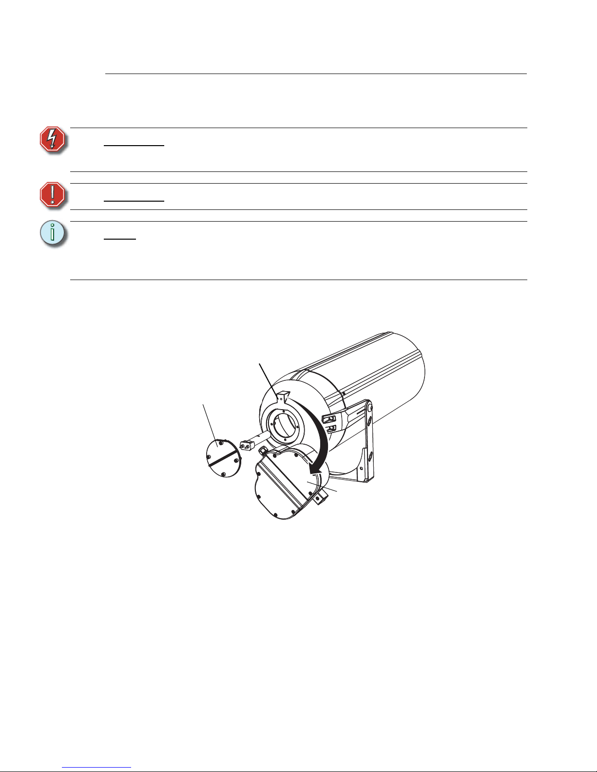
Step 2: Loosen the screw securing the ballast.
Figure-2 Ballast and Reflector Housing Base on the Back of the Fixture.
Step 3: Rotate the ballast to reveal the lamp cap.
Step 4: Loosen the four screws of the lamp cap.
The screws are captive so they will stay in the cap.
Step 5: Pull the lamp assembly straight out of the fixture.
Step 6: Carefully pull the old lamp out of the ceramic base.
Step 7: Holding it by the base, remove the new HID lamp from its box.
WARNING:
Do not replace the lamp when it is raining or snowing. Do not stand in water
while replacing the lamp. Failure to follow this warning can result in serious
injury or death.
WARNING:
Disconnect power and let the lamp cool before replacing.
Note:
Verify that the HID lamp you intend to install is suitable for your fixture’s ballast.
See Lamp and Ballast Information, page 2. Operating HID lamps above their rated
voltage reduces lamp life and can cause premature lamp failure.
The facility’s voltage must match the voltage of the fixture and its ballast.
Blast screw
Rotate ballast
Lamp cap
Page 6
4 Source Four XT HID Zoom User Manual
.
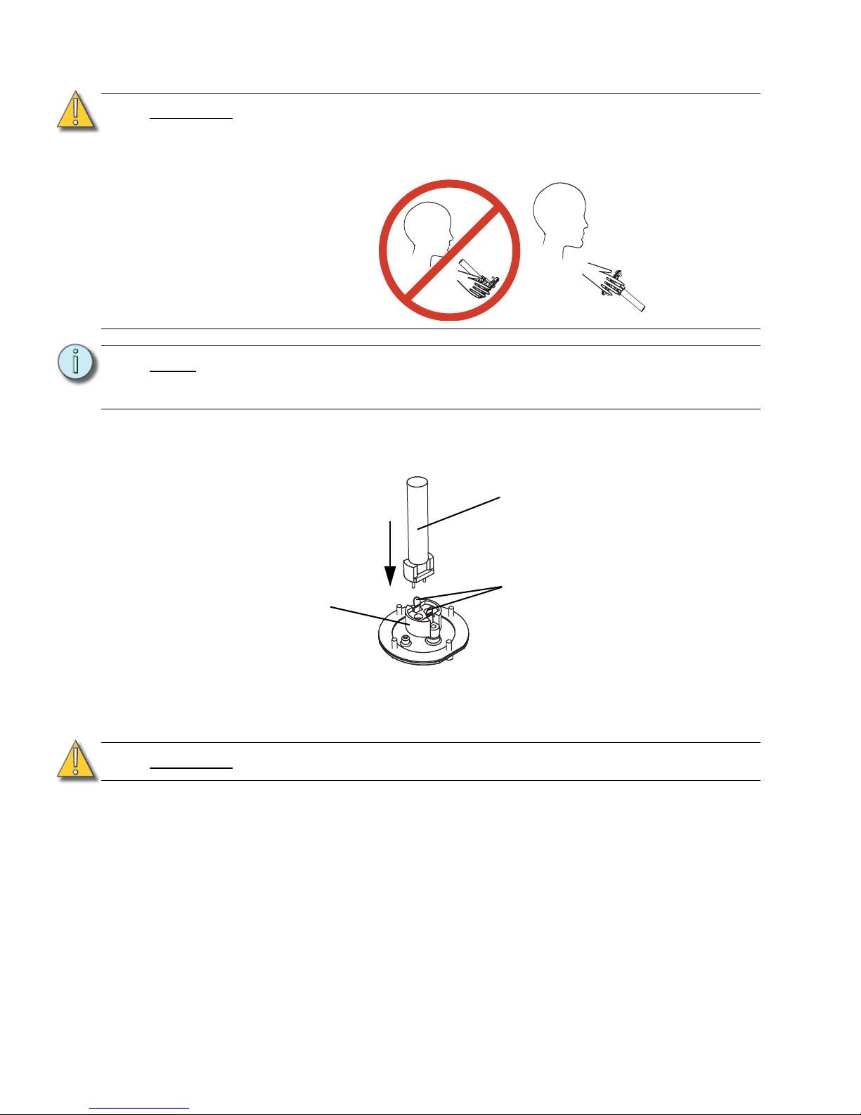
Step 8: Align the flat sides of the lamp base with the lamp retaining clips on both sides of the
socket.
Figure-3 Inserting the Lamp into the Lamp Housing.
Step 9: Push down on the lamp base until the lamp seats firmly.
When properly installed, the base of the lamp will be secured by the lamp retaining clips.
Step 10: Reinstall the lamp assembly by aligning the lamp cap with the fixture.
Ensure the wire is pushed aside and not touching the lamp.
Step 11: Tighten the screws in a zig-zag pattern.
CAUTION:
Use caution when installing or replacing any lamp.
When installing or replacing lamp, be sure to point the lamp away from your face
and away from others before inserting it firmly into the assembly.
This may prevent injuries if the lamp should break.
Note:
To avoid premature lamp failure, do not touch the lamp glass. If you do, clean it
carefully with isopropyl alcohol and a clean lint-free cloth. Allow to dry before
operation.
CAUTION:
Improperly installed lamps cause premature lamp failure and socket problems.
INCORRECT
CORRECT
HID lamp
Lamp housing
Lamp retainer clips
Page 7
5
Installation
Install on a suitable, rigid permanent base with secured bolts. This can include poured concrete
pads, factory-supplied pole-top and wall-mount brackets, and other attachments which meet the
published weight and wind-load requirements for the fixture. Use the full-sized template that is
included in the installation instructions or download the template at www.etcconnect.com.
• Weight: 39 pounds, exclusive of accessories and/or color filters and patterns.
• Wind Load: 1.4 cubic feet of effective projected area (EPA).
Electrical
The fixture is completely pre-wired at the factory, and there is no need for entry into the ballast
housing.
WARNING:
Do not use this fixture with a damaged power lead. If the power lead
(cordset) is damaged, it must be replaced. Failure to follow this warning can
result in serious injury or death.
WARNING:
All third-party mounting hardware should be corrosion-resistant and
designed for use where installed.
CAUTION:
The fixture must be grounded and wired in accordance with national, state and
local electrical codes. Failure to do may result in serious personal injury.
Page 8
6 Source Four XT HID Zoom User Manual
Removing and Installing the Barrel
The barrel can be removed for adjustments, focusing, installing patterns, and cleaning the lenses.
To remove the barrel:
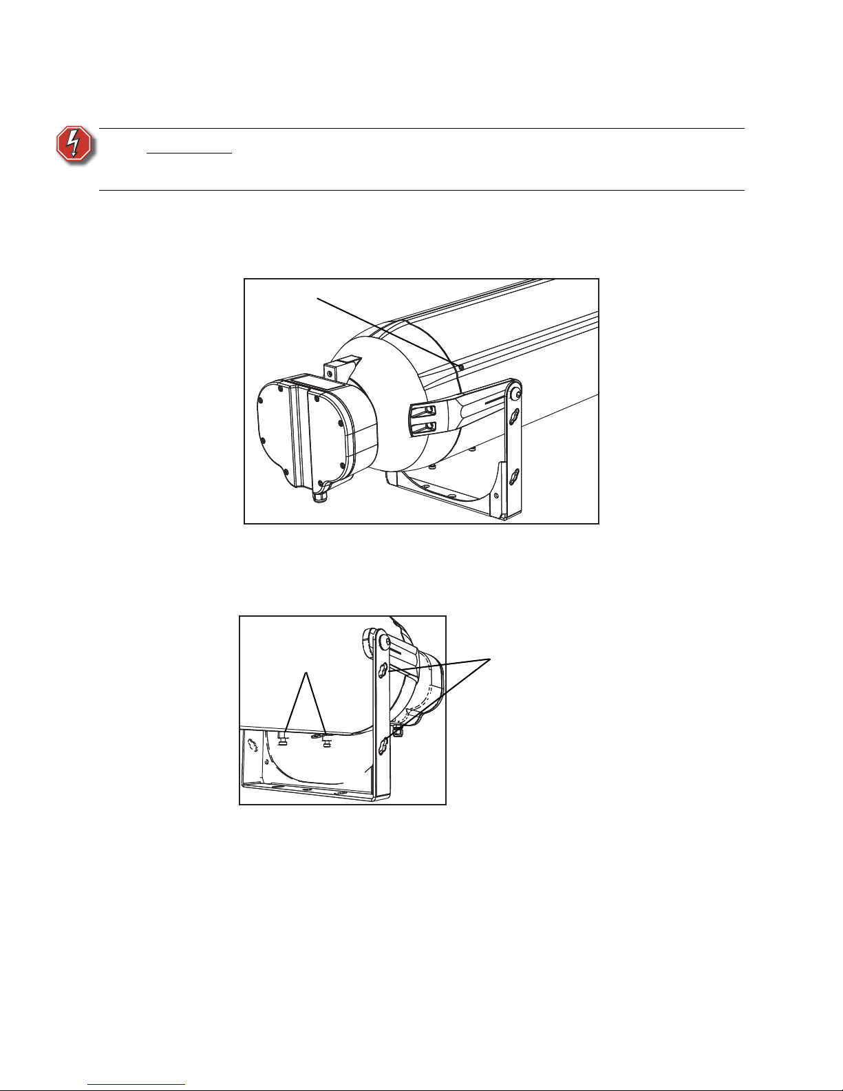
Step 1: Loosen the three 4mm hex screws around the barrel.
Do not remove the screws but loosen enough to clear the reflector housing.
Figure-4 4mm Hex Screws on the Barrel.
Step 2: Slide the barrel off the fixture.
Step 3: Use the two studs on the barrel to hang it on the side of the yoke while you work.
Figure-5 Barrel Hanging Studs and Slots on Yoke.
Step 4: Use the safety loop and the optional safety cable to secure the barrel if needed.
To install the barrel:
Step 1: Slide the barrel down over the lens rails, aligning the three ridges of the barrel with the
ridges on the housing.
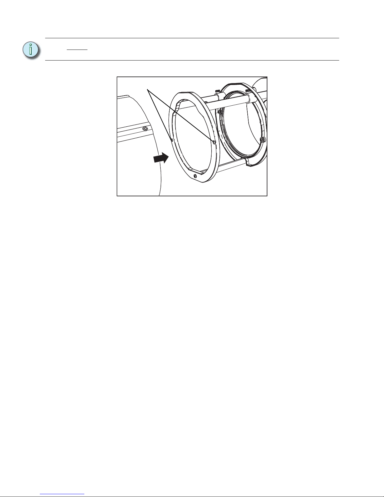
Step 2: With the barrel down as far as it will go, rotate it until the internal locating pins go in the
locating holes.
WARNING:
Do not remove the barrel and expose the interior of the fixture to water, such
as rain or snow. Do not stand in water while installing or servicing the
fixture. Failure to follow this warning can result in serious injury or death.
4mm hex
screw
Barrel hanging slots
Barrel hanging studs
Page 9
7
Figure-6 Internal Locating Holes in Top Ring.
Step 3: Tighten the three 4mm hex screws around the barrel.
It is recommended to partially tighten each screw, working around the barrel until all are
snug. Tightening the screws draws the barrel down to the self-sealing gasket.
Note:
The barrel will not seal properly until the internal locating pin goes through the
locating hole.
Barrel locating holes
Page 10
8 Source Four XT HID Zoom User Manual
Adjustments
Focusing the Beam
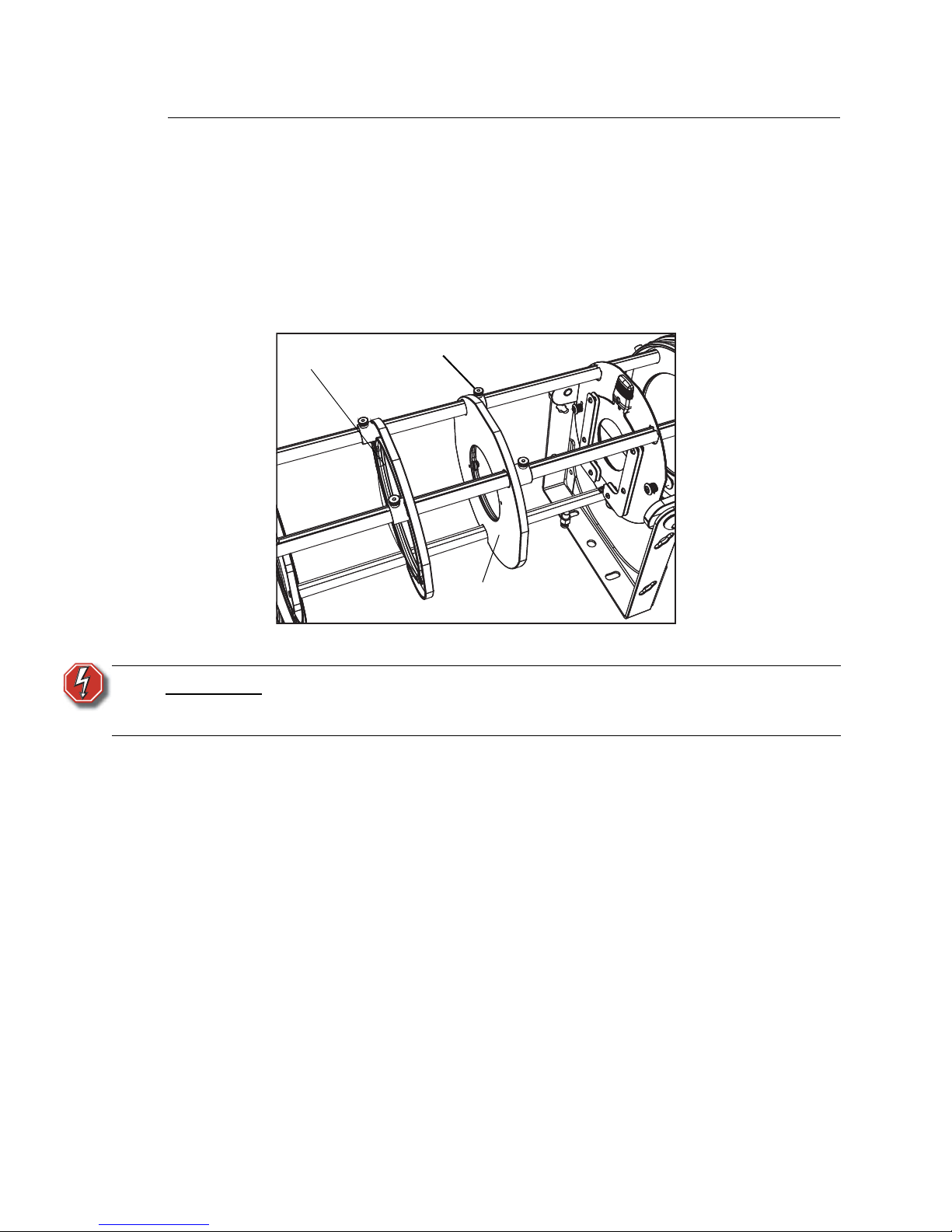
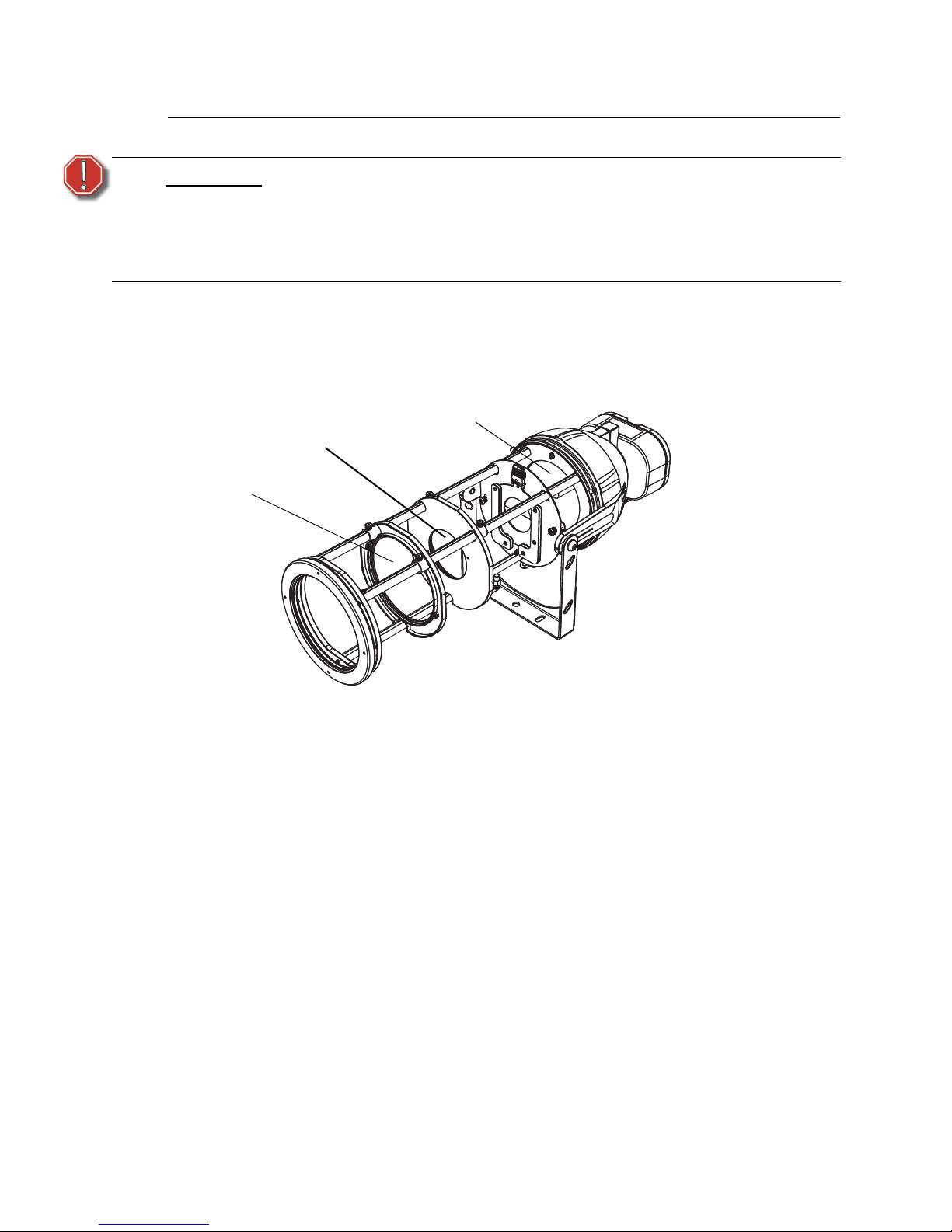
Two internal lenses control the size and focus of the light beam. Each lens is mounted in frames
and these frames slide along the rails. The lens frames are secured in the desired location with two
knurled thumb screws.
• The field lens is nearest the lamp and controls the width of the beam.
• The focus lens is furthermost from the lamp and controls the focus of the beam.
Figure-7 Lens Arrangement.
Step 1: Remove the barrel as described in Removing and Installing the Barrel, page 6.
Step 2: Turn the Source Four XT on and aim it at a flat surface.
Step 3: Pull the shutters outward so that the aperture is fully open. Refer to Adjusting Shutters,
page 11.
Step 4: Loosen the two knurled thumb screws on the field lens holder.
WARNING:
Do not remove the barrel and expose the interior of the fixture to water, such
as rain or snow. Do not stand in water while installing or servicing the
fixture. Failure to follow this warning can result in serious injury or death.
Focus lens
and frame
Field lens
and frame
Thumb screw
Page 11
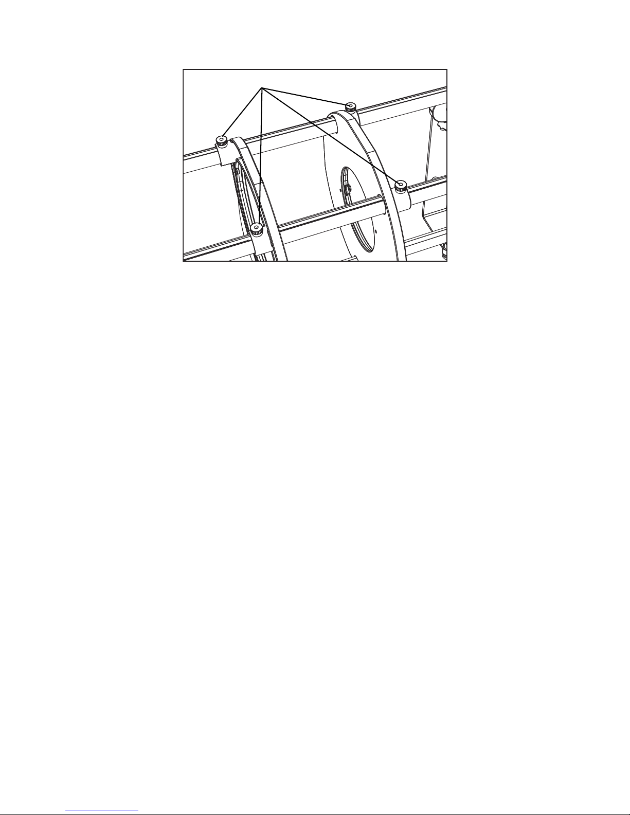
9
Figure-8 Thumb Screws.
Step 5: Gently slide the field lens back and forth on the rails until you get the desired width of the
beam and then finger-tighten the thumb screws.
• Moving the lens towards the lamp narrows the field angle of the beam.
• Moving the lens away from the lamp widens the field angle of the beam.
Step 6: Loosen the two knurled thumb screws on the focus lens holder.
Step 7: Gently slide the focus lens back and forth on the rails until you get the desired focus of
the beam and then finger-tighten the thumb screws.
• Moving the lens towards the lamp sharpens the focus so that the edges are hard.
• Moving the lens away from the lamp softens the focus so that the edges are soft.
Step 8: Shape the beam with the shutters and install a pattern if needed. See Shaping the Beam,
page 10.
Lens holder thumb screws
Page 12
10 Source Four XT HID Zoom User Manual
Shaping the Beam
The beam can be shaped using patterns and the shutters. The beam can also be colored with
colored glass in the pattern holder.
Pattern and Color Projection
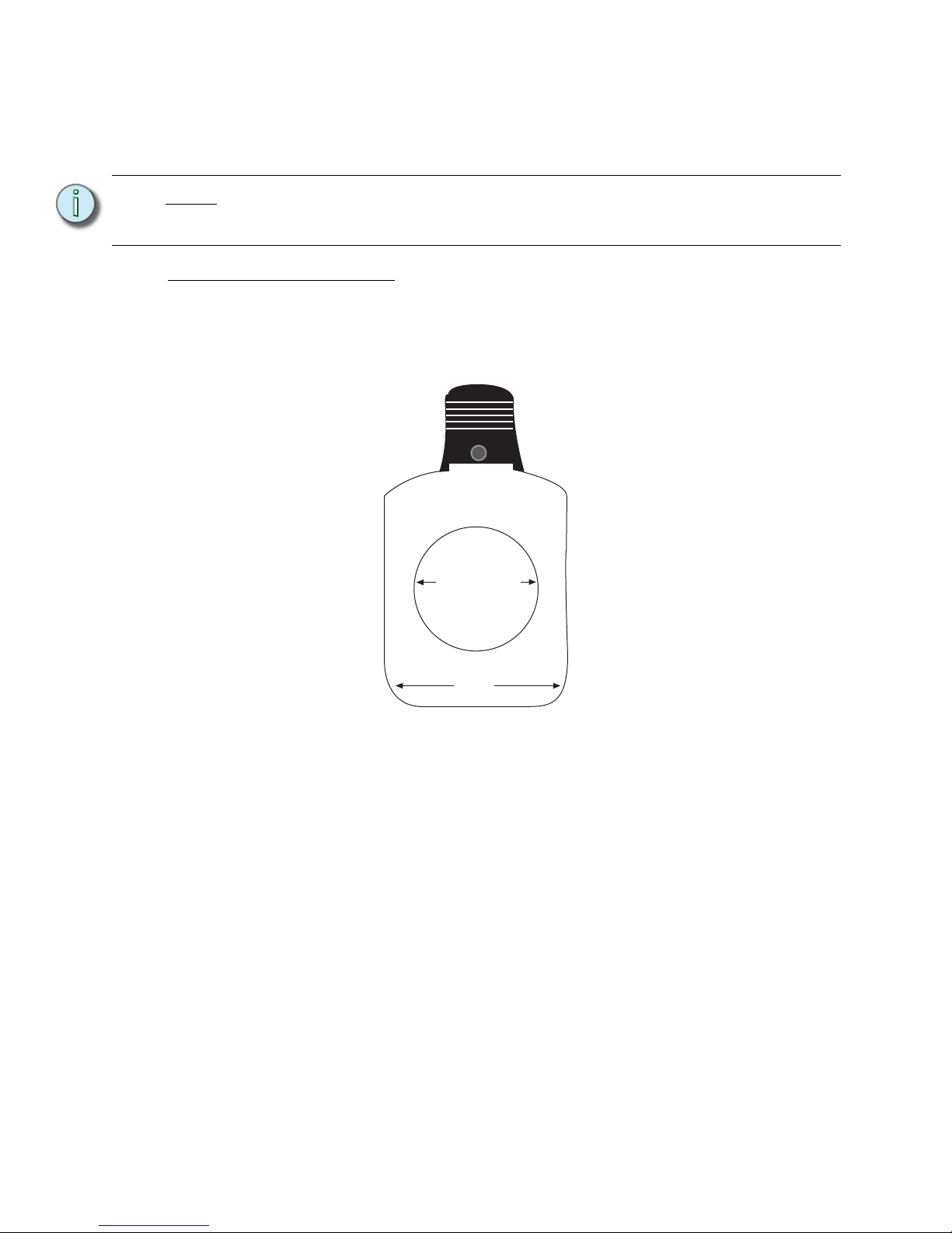
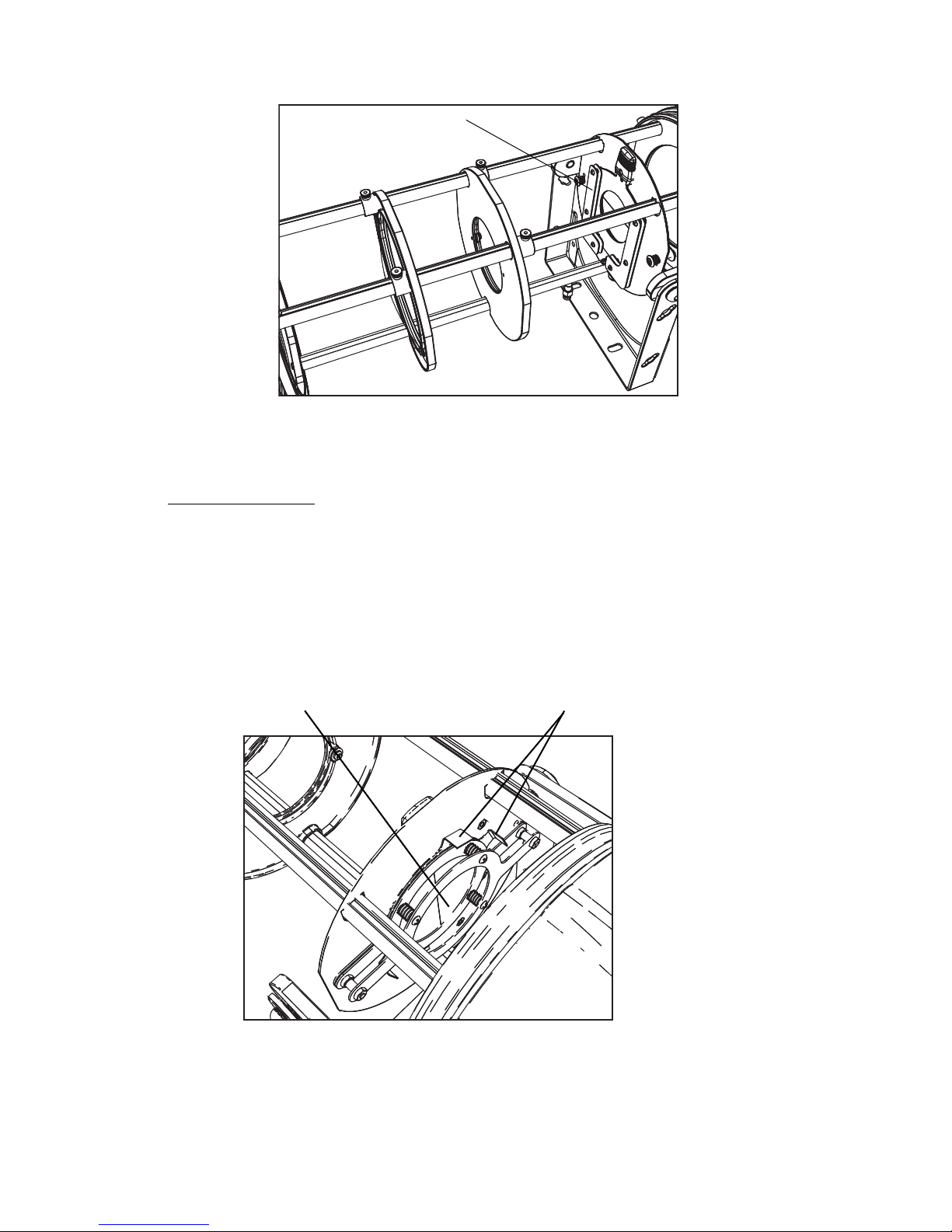
The two pattern holder slots are inside the fixture and immediately in front of the shutters. The
holder slots accommodate B-size and glass pattern holders. The holder holds 2.5 and 2.75 inch
diameter patterns. One pattern holder for steel patterns is supplied with the fixture. Additional glass
or steel pattern holders are available from ETC.
Figure-9 Pattern Holder Dimensions.
Step 1: Remove the barrel as described in Removing and Installing the Barrel, page 6.
Step 2: Insert the pattern into the pattern holder upside down and in reverse of the desired
projection.
Note:
The projected beam is the inverse of the inserted patterns and shutter
adjustments. That is, for a pattern to be projected right side up, it is inserted upside
down and backwards. Likewise, moving a shutter affects its opposite image.
2.75"
Diameter
3.70"
Page 13
11
Figure-10 Pattern Holder Location.
Step 3: Adjust the focus lens if needed. See Focusing the Beam, page 8.
Step 4: Reinstall the barrel.
Adjusting Shutters
Use the shutters to shape the light beam. For example, you may want to use them to block the light
from falling on part of a building. Or you may want to frame a sign. The shutters are held in place
by a spring shutter retention system. You do not need to tighten or loosen the screws to make
adjustments.
Step 1: Remove the barrel as described in Removing and Installing the Barrel, page 6.
Step 2: Turn the Source Four XT on and aim it at the structure you are illuminating.
Step 3: Pull the shutters outward so that the aperture is fully open.
Figure-11 Shutters and Their Tabs.
Step 4: Use the tabs on the shutters to move them to block the beam as needed.
Keep in mind that the blocking is reversed.
Step 5: Reinstall the barrel.
Pattern holder slots
Shutters
Shutter tabs
Page 14
12 Source Four XT HID Zoom User Manual
Adjusting the Angle
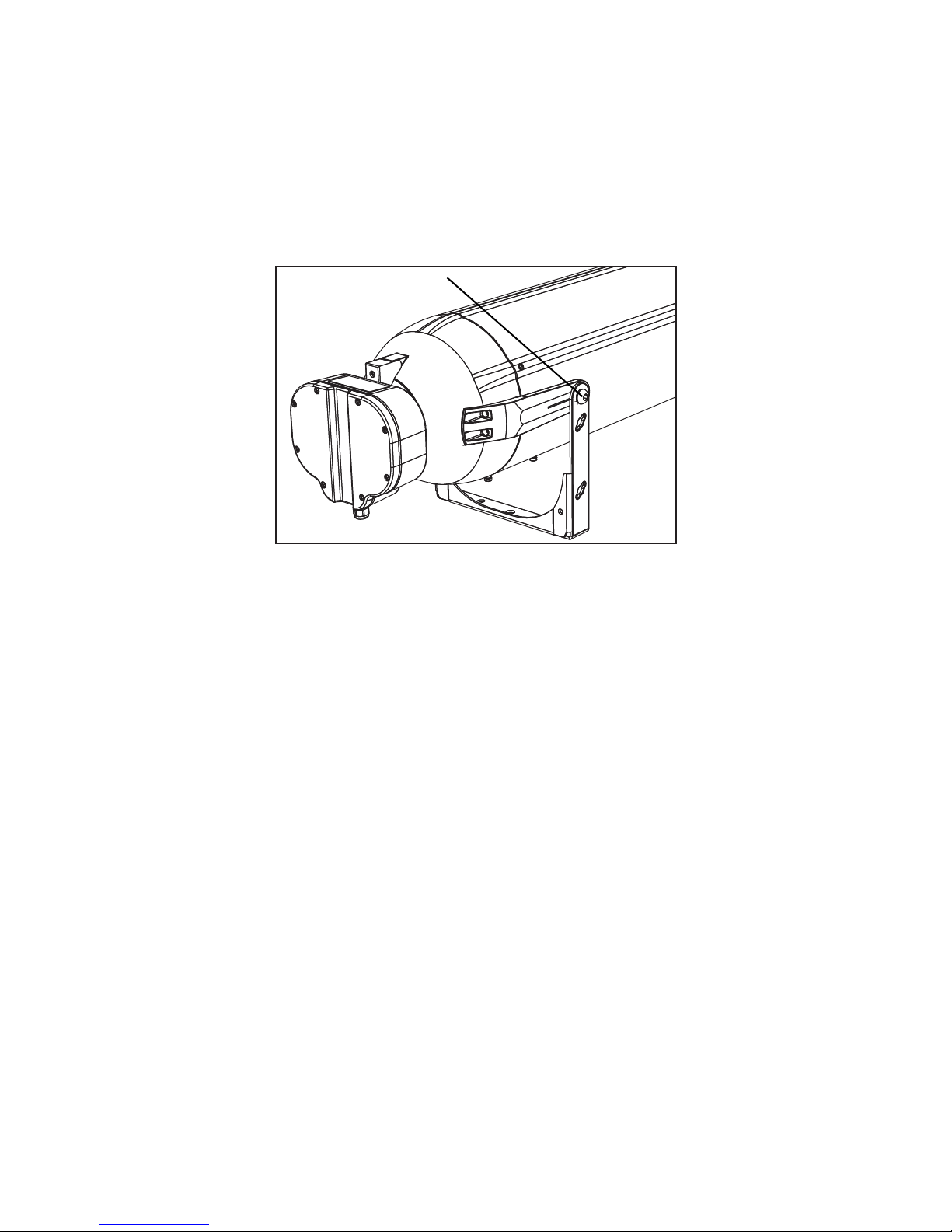
The Source Four XT provides the capability to adjust the fixture angle.
• The standard yoke provides +12 to -7° horizontal tilt when ground-mounted.
• The standard yoke provides +45 to -40° when bracket or pole mounted.
• The optional long yoke allows +90 to -35° fixture angle, including straight up or down
aiming.
Figure-12 Yoke Locking Screw.
Step 1: Using an 8mm hex wrench, loosen the two yoke locking screws.
Do not remove them.
Step 2: Tilt the fixture to the desired position.
Step 3: Tighten the two yoke locking screws to secure in position.
Yoke locking screw
Page 15
13
Cleaning the Lenses and Reflector
Replace lenses if they contain visible damage (cracks or deep scratches) that may impair their
effectiveness.
Cleaning Glass Lenses
Figure-13 Internal Glass Lenses.
Step 1: Remove the barrel.
Refer to Removing and Installing the Barrel, page 6.
Step 2: If needed, move the lenses to access both sides of the lenses.
Step 3: Remove dust with a blast of oil-free air or wipe with a clean, lint-free cloth. Isopropyl
alcohol, distilled water or a 50%-50% mixture of each can be used to clean the glass
surface.
Step 4: If the reflector needs to be cleaned, refer to Cleaning the reflector, page 14.
Step 5: Return the lenses to the required positions if needed.
Step 6: Replace the barrel.
WARNING:
Do not use ammonia-based or other harsh commercial cleaners. Clean lens
and reflector only as directed.
Commercially available glass cleaning agents should be avoided as they
may contain ammonia, other harsh chemical detergents or abrasive agents.
These cleaners may damage the glass surface and the Anti-Reflective
coatings. Do not immerse or soak the glass in any cleaning solution.
Focus lens
Field lens
Reflector
Page 16

14 Source Four XT HID Zoom User Manual
Cleaning the reflector
To quickly clean the reflector, remove the lens tube and clean the dust from the reflector with a blast
of oil-free air. You may also wipe the reflector with a clean lint-free cloth. If either method is not
sufficient, follow these steps. Refer to Figure-13.
Step 1: To protect the lamp during cleaning, remove the lamp assembly. Refer to Replacing the
HID Lamp, page 3.
Step 1: Remove the barrel.
Refer to Removing and Installing the Barrel, page 6.
Step 2: Remove dust with a blast of oil-free air or wipe with a clean, lint-free cloth. Isopropyl
alcohol, distilled water or a 50%-50% mixture of each can be used to clean the glass
surface.
Step 3: Gently wipe the reflector.
Step 4: Reinstall the barrel.
Step 1: Reinstall the lamp assembly.
WARNING:
Disconnect power and allow the lamp to cool down before attempting to
clean the reflector.
Page 17

15
Page 18

16 Source Four XT HID Zoom User Manual
Page 19

17
Page 20

Corporate Headquarters
3031 Pleasant View Road, P.O. Box 620979, Middleton, Wisconsin 53562-0979 USA Tel +608 831 4116 Fax +608 836 1736
London, UK
Unit 26-28, Victoria Industrial Estate, Victoria Road, London W3 6UU, UK Tel +44 (0)20 8896 1000 Fax +44 (0)20 8896 2000
Rome, IT
Via Pieve Torina, 48, 00156 Rome, Italy Tel +39 (06) 32 111 683 Fax +44 (0) 20 8752 8486
Holzkirchen, DE
Ohmstrasse 3, 83607 Holzkirchen, Germany Tel +49 (80 24) 47 00-0 Fax +49 (80 24) 47 00-3 00
Hong Kong Rm 1801, 18/F, Tower 1 Phase 1, Enterprise Square, 9 Sheung Yuet Road, Kowloon Bay, Kowloon, Hong Kong Tel +852 2799 1220 Fax +852 2799 9325
Service:
(Americas) [email protected]
(UK) [email protected] (DE) [email protected]
(Asia) [email protected]
Web:
www.etcconnect.com
Copyright © 2011 ETC. All Rights Reserved. Product information and specifications subject to change.
7065M1200
Rev B Released 2011-11
 Loading...