

Page 1

Assembly Guide
Production Dates: September 2004 - Present
ATTENTION: The part numbers listed in this guide may differ from the parts
required for your particular Source Four fixture. Part numbers for
fixtures change occasionally as parts are replaced or upgraded.
To ensure that you are ordering the proper part for your specific
fixture, please contact your ETC dealer, or ETC Customer Service
for assistance.
Copyright © 2007 Electronic Theatre Controls, Inc.
All Rights reserved.
Product information and specifications subject to change.
Part Number:
7061M2500-06.01
Released: August 2007
Rev A
Page 2

Table of Contents
Basic Assembly . . . . . . . . . . . . . . . . . . . . . . . . . . . . . . . . . . . . . . . . .1
Lamp Socket Assembly . . . . . . . . . . . . . . . . . . . . . . . . . . . . . . . . . . .2
Assemble lamp socket. . . . . . . . . . . . . . . . . . . . . . . . . . . . . . . . .3
Housing Assembly . . . . . . . . . . . . . . . . . . . . . . . . . . . . . . . . . . . . . . .4
Assemble housing . . . . . . . . . . . . . . . . . . . . . . . . . . . . . . . . . . . .5
Cleaning the reflector. . . . . . . . . . . . . . . . . . . . . . . . . . . . . . . . . .6
Cleaning the lens . . . . . . . . . . . . . . . . . . . . . . . . . . . . . . . . . . . . .6
Lens identification . . . . . . . . . . . . . . . . . . . . . . . . . . . . . . . . . . . .7
ETC®, Emphasis®, Expression®, Insight™, Imagine™, Focus™, Express™, Unison®, Obsession® II, ETCNet2™,
EDMX™, Source Four
of Electronic Theatre Controls, Inc. in the United States and other countries.
All other trademarks, both marked and not marked, are the property of their respective owners.
i Table of Contents
®
, Revolution®, Sensor®, and WYSILink™ are either registered trademarks or trademarks
Page 3

Basic Assembly
DI
RECTI
ON
L
AB
EL
Figure 1
9
10
11
12
1
2
3
4
7
6
5
4
3
8
13
LABEL
DIRECTION
Reference
Number
Part
Number
Description Quantity
Required
1 7061A2001 Lamp socket assembly, black 1
7061A2001-1 Lamp socket assembly, white 1
2 7061A3006 Bracket, yoke, black 1
7061A3006-1 Bracket, yoke, white 1
3 HW5172 Bolt, hex, 1/4-20 x 1”, black zinc 2
4 HW522 Washer, flat, 1/4, black zinc 2
5 HW5125 Bolt, carriage, 5/16-18, black zinc 1
6 HW5126 Washer, flat, 5/16, black zinc 1
7 HW8144 Handle, yoke knob, 5/16-18 1
8 7061A2015 Housing Assembly, EA, black 1
7061A2015-1 Housing Assembly, EA, white 1
9 7061A4002 Lens, clear, VNSP 1
10 7061A4003 Lens, stipple, NSP 2
11 7061A4005 Lens, medium flood, MFL 1
12 7061A4006 Lens, wide flood, WFL 1
13 7061A4029 Lens stop 1
Basic Assembly 1
Page 4
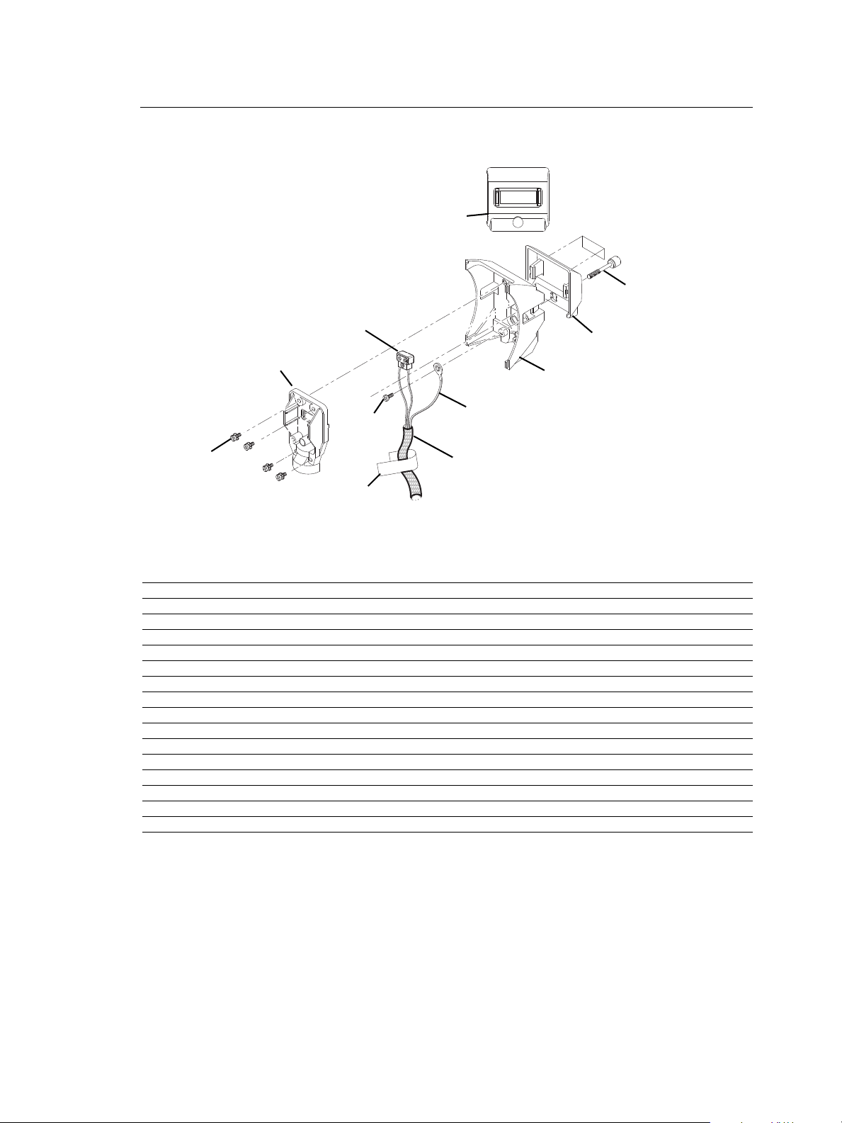
Lamp Socket Assembly
WARNING!
Figure 2
1
2
3
4
5
6
7
8
9
10
11
750
WARNING!
Reference
Number
1 7060A3025 Screw, 1/4-20 x 1.55, knurled 1
2 7060A4019 Label, Fixture Warning 1
3 7061A3023 Burner, casting, black 1
4 7061A3024 Strain relief, black 1
5 7061A4011 Focus handle, black 1
6 7061B7002 Ground Wire, 48” 1
7 HW2182 Screw, 6-32 x 1/4, PhPh, Taptite, zinc 1
8 HW3105 Screw, 8-32 x 1/2, PhPh, Taptite, SEMS 4
9 M706 Complete TP 22 CLCM assembly 1
10 W6195 Sleeve, fiberglass, 39”, black 1
11 7060A4094 Label, 750W, handle, black 1
Part
Description Quantity
Number
7061A3023-1 Burner, casting, white 1
7061A3024-1 Strain relief, white 1
7061A4011-1 Focus handle, white 1
W689-1 Sleeve, fiberglass, 39”, white 1
7060A4095 Label, 750W, handle, white 1
Required
2 Source Four PAR Assembly Guide
Page 5

Assemble lamp socket
Figure 3
TP22
assembly (9)
Knurled head
screw hole
Sleeving (10)
Ground wire (6)
and 6-32 x 1/4
screw (7)
Strain relief
casting (4,)
Burner casting
(3)
Tighten 2
Tighten 1
Tighten 3
Tighten 4
Tools Required:
• #2 Phillips screwdriver
Step 1: Install the ground wire (6) and the TP22 assembly (9) in the sleeving (10). See
Figure 3.
Step 2: Snap the focus handle (5) onto the burner (3). See Figure 2.
Step 3: Secure the ground wire lug (6) onto the burner casting (3) using screw (7).
Note:
Step 4: Place the TP22 assembly (9) into the burner casting (3). See Figure 3.
Position the wires with the green ground wire on top of the two TP22 white leads.
Make sure the green ground wire is not touching any part of the burner casting.
Step 5: Insert the screws (8) into the four positions in the strain relief casting (4). See
Figure 3.
Step 6: Position the sleeving assembly (10) as shown in Figure 3. Fold the sleeving so it
fits cleanly in the slot between the burner and the strain relief.
Step 7: Place the strain relief (4) on the burner casting (3). Loosely attach the screws (8).
The TP22 assembly (9) must be centered in the strain relief opening (4). See
Figure 3.
Step 8: To guard against stripping the screws, tighten them in the order shown in
Figure 3.
Step 9: Make sure the focus handle is secure, then insert the knurled head screw (1)
through the handle (5) into the burner casting (3). Tighten securely.
Lamp Socket Assembly 3
Page 6

Housing Assembly
Figure 4
1
3
2
4
5
5
6
7
(2 placesboth sides)
8
9
10
11
12
13
14
Reference
Number
1 7060A3100 Clip, gel retainer 1
2 7061A3013 Spring clip, rotator 1
3 7061A3014 Reflector, molded glass, coated, black 1
4 7061A3025 Barrel, right, black 1
7061A3025-1 Barrel, right, white 1
5 7061A2019 Barrel, left, black 1
7061A2019-1 Barrel, left, white 1
6 7061A3029 Clip, rotator, pressure 1
7 7061A4001 Pad, silicon, reflector mount 4
8 7061A4012 Lens rotator, black 1
9 7061A4029 Lens stop 1
10 7061A4030 Label, ETC S4 PAR, black 1
11 HW492 Screw, 10-32 x 5/8, PhPH, Taptite 3
12 HW4145 Screw, 10-32 x 3/8, PhPH, Taptite, BO 1
13 HW6128 Plug, focus knob, black 1
14 HW750 Spring, retainer 1
Part
Description Quantity
Number
7061A3014-1 Reflector, molded glass, coated, white 1
7061A4012-1 Lens rotator, white 1
7061A4030-1 Label, ETC S4 PAR, white 1
HW6128-1 Plug, focus knob, white 1
Required
4 Source Four PAR Assembly Guide
Page 7

Assemble housing
ALIGN ROTATOR CLIP
ALIGN ZOOM LENS
C
T
E
Source Four PAR
Figure 5
Left barrel alignment arrow
Label (10) alignment
Align rotator spring clip (2) on rotator
with rotator tab on left barrel (6)
Align rib on reflector (8) with left barrel (6) pocket
Tools Required:
• Minimally padded work surface (cardboard, carpet, or rubber mat recommended)
• Phillips screwdriver
WARNING:
Step 1: Install the reflector mount silicon pads (7) in the left barrel assembly (6). Install
Step 2: Install the lens stop (9) and rotator spring clip (2) into the lens rotator (8). Install
Step 3: Install the rotator pressure clip (6) into the left barrel (5) and attach using screw
Step 4: Install the gel retainer clip (1) and the spring retainer (14) into the right barrel (4).
Step 5: Install the reflector (3) into the left barrel (5). Align the rib on the reflector with the
Step 6: Attach the right barrel (4) to the left barrel (5) using three screws (11). Hand
Step 7: Clean reflector. See “Cleaning the reflector” on page 6.
Step 8: Check for ease of movement of the gel clip retainer (1). The clip should latch into
Step 9: Check for smooth rotation of the lens rotator (8).
Step 10: Snap the focus knob plug (13) into the bottom of the fixture.
Step 11: Attach label (10) onto the left barrel as shown in Figure 5.
This procedure may crack or break the reflector. Always wear gloves, safety
glasses, and a dust mask when performing this procedure.
the pads in two places on both sides. See Figure 4.
the lens rotator into the left barrel (5).
(12).
left barrel pocket as shown in Figure 5.
tighten only (25 in. lbs.).
the left barrel in the down position and be free of binding.
Housing Assembly 5
Page 8

Step 12: Hold the lens by the edge and position it so the wave side faces the rear of the
Spring clip
Retaining clip
Lens Catcher
Spring clip
Retaining clip
Tab
Figure 6
fixture. See Figure 6.
Step 13: From the top of the fixture, slide the lens behind the lens catchers and position it
behind the tabs on the bottom of the lens rotator ring.
Step 14: Gently push the top of the lens inward until it snaps behind the spring clip.
Step 15: Install the lamp socket assembly (See “Assemble lamp socket” on page 3.) to the
barrel housing assembly and secure with brass knurled screw on rear of lamp
socket assembly.
Cleaning the reflector
WARNING:
Step 1: Remove the lens to expose the reflector so you can access it from the front of the
Step 2: Remove dust with a blast of oil-free air or wipe with a clean, lint-free cloth.
Step 3: Reinstall a lens before using the luminaire.
Do not use ammonia-based or other harsh commercial cleaners. Clean
reflector only as directed.
Commercially available glass cleaning agents should be avoided as they
may contain ammonia, other harsh chemical detergents or abrasive agents.
These cleaners may damage the glass surface and the Anti-Reflective
coatings. Do not immerse or soak the glass in any cleaning solution.
luminaire.
Isopropyl alcohol, distilled water or a 50%-50% mixture of each can be used to
clean the glass surface.
Cleaning the lens
WARNING:
Remove dust with a blast of oil-free air or wipe with a clean, lint-free cloth. Isopropyl alcohol,
distilled water or a 50%-50% mixture of each can be used to clean the glass surface.
Do not use ammonia-based or other harsh commercial cleaners. Clean lens
only as directed.
Commercially available glass cleaning agents should be avoided as they
may contain ammonia, other harsh chemical detergents or abrasive agents.
These cleaners may damage the glass surface and the Anti-Reflective
coatings. Do not immerse or soak the glass in any cleaning solution.
6 Source Four PAR Assembly Guide
Page 9

Lens identification
Figure 7
Lenses for the Source FourPAR come in four varieties. The type or beam spread can be
identified by the texture of the lens.
VNSP
NSP
XWFL
(Optional)
Very narrow spot
Clear glass
15° Round beam shape
MFL
Medium flood
Fewer facets, sized 6 x 22mm
21° x 34° Oblong beam shape
Narrow spot
Stipple glass (slight diffuse texture)
19° Round beam shape
WFL
Wide flood
Many facets, sized 6 x 12mm
30° x 51° Oblong beam shape
Extra-wide, or buxom, lens
Molded, borosilicate lens, multi-faceted
60° Round beam shape
Housing Assembly 7
Page 10

8 Source Four PAR Assembly Guide
Page 11

Housing Assembly 9
Page 12

Corporate Headquarters
London, UK
Rome, IT
Unit 26-28, Victoria Industrial Estate, Victoria Road, London W3 6UU, UK Tel +44 (0)20 8896 1000 Fax +44 (0)20 8896 2000
Via Ennio Quirino Visconti, 11, 00193 Rome, Italy Tel +39 (06) 32 111 683 Fax +39 (06) 32 656 990
Holzkirchen, DE
3031 Pleasant View Road, P.O. Box 620979, Middleton, Wisconsin 53562-0979 USA Tel +608 831 4116 Fax +608 836 1736
Ohmstrasse 3, 83607 Holzkirchen, Germany Tel +49 (80 24) 47 00-0 Fax +49 (80 24) 47 00-3 00
Hong Kong Rm 1801, 18/F, Tower 1 Phase 1, Enterprise Square, 9 Sheung Yuet Road, Kowloon Bay, Kowloon, Hong Kong Tel +852 2799 1220 Fax +852 2799 9325
Service:
(Americas) service@etcconnect.com
Web:
www.etcconnect.com
7061M2500-06.01
Rev A Released 08/2007
Copyright © 2007 ETC. All Rights Reserved. Product information and specifications subject to change.
(UK) service@etceurope.com (DE) techserv-hoki@etcconnect.com
(Asia) service@etcasia.com
 Loading...