

Page 1
ORDER DIRECTLY TODAY AT: www.BulbAmerica.com or CALL TOLL FREE 888-505-2111
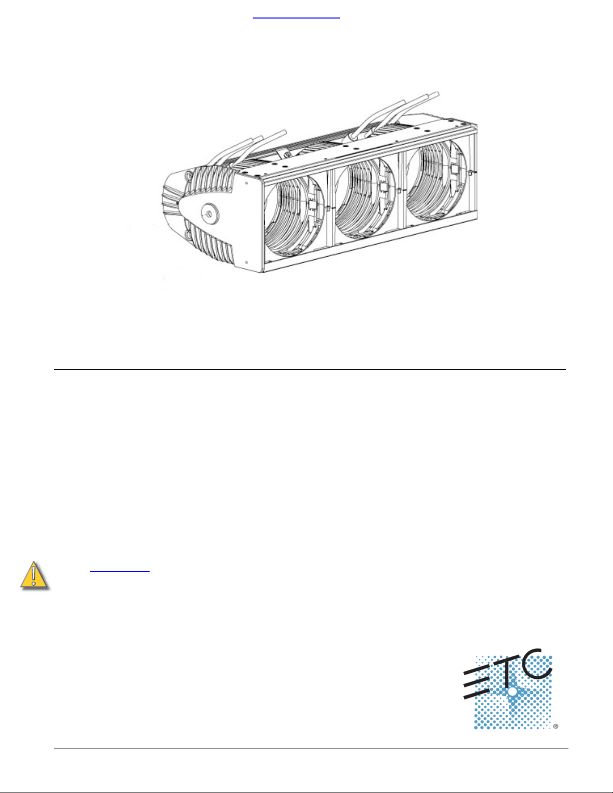
Source Four MultiPAR™ User Guide
Source Four MultiPAR guidelines
Please note the following precautions prior to use:
• Do not mount the Source Four MultiPAR
• Do not operate the Source Four MultiPAR witho
• Always hang the Source Four MultiPAR with color frames held securely behind the
MultiPAR retaining channel.
• Safety cables are provided with ea
the batten by threading the safety cable through the end cap holes when hanging
the unit.
on or near combustible surfaces.
ut lenses properly installed.
ch MultiPAR. Be certain to secure the MultiPAR to
Power requirements
The Source 4 MultiPAR has several different standard, as well as custom configurations of electrical circuitry. Make certain you
PAR and that you have sufficient power (dimmer ca
CAUTION:
Make sure that the total wattage used by your MultiPAR
does not exceed the power available by dimmer.
are familiar with the wiring of the Multi-
pacity) to operate the fixture.
Source Four MultiPAR • 1
Page 2
ORDER DIRECTLY TODAY AT: www.BulbAmerica.com or CALL TOLL FREE 888-505-2111
Installing the HPL lamp
1. Disconnect power before installing the lamp.
2. Let the lamp cool before replacing.
3. Loosen the captured screw on the back of the raceway and open the raceway lid.
4. The raceway lid is designed to remain open using gravity. If lid swings shut,
reposition the MultiPAR unit using the hanging irons or trunnions to lock the unit
in position.
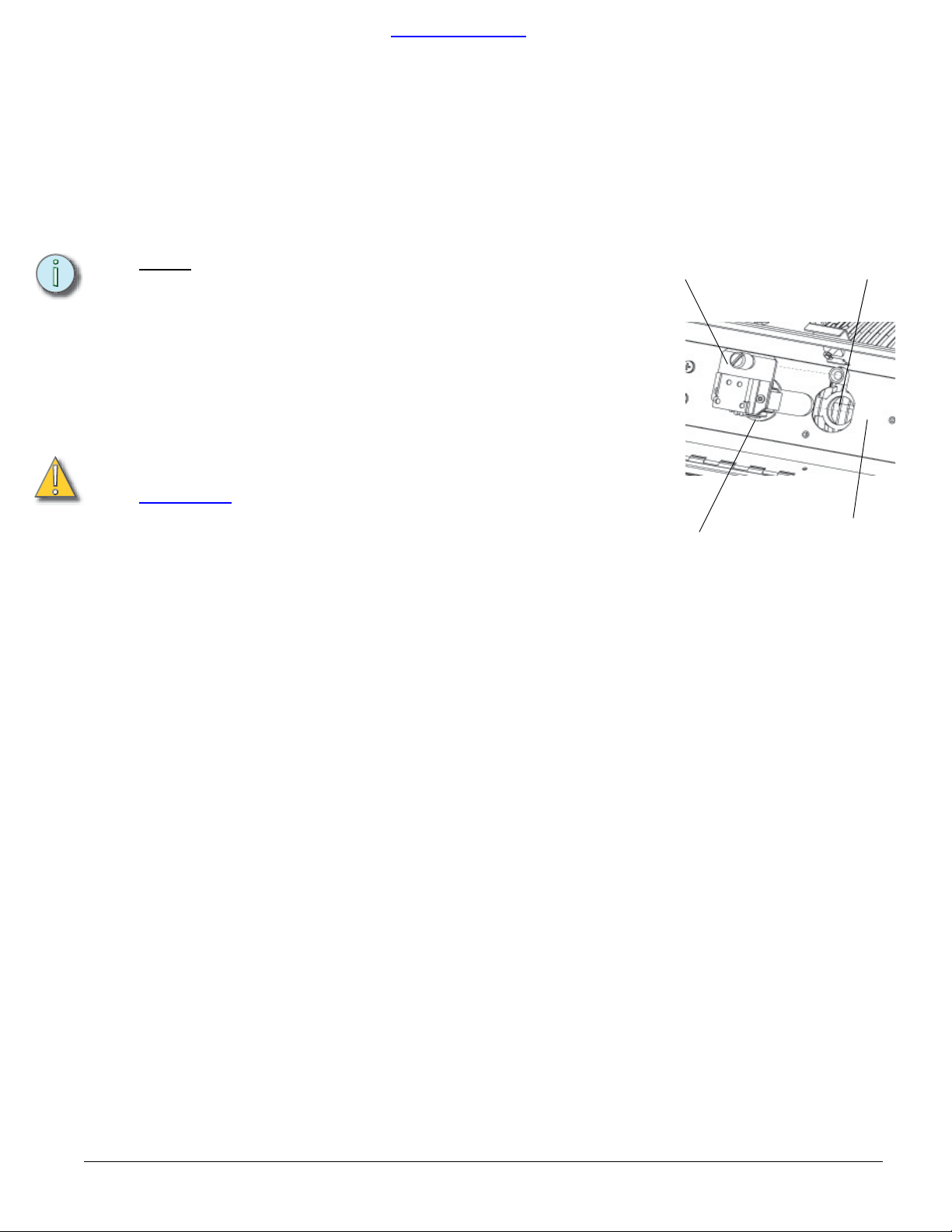
5. Remove lamp socket by loosening the gnurled knob and removing the socket
assembly. Remove the HPL lamp from its box, holding it by the base.
Note:
To avoid premature lamp failure, do not touch the lamp glass
with your fingers. If you touch the lamp during installation,
clean
it carefully with rubbing alcohol and a clean, lint-free
cloth before operation.
6. Insert lamp base into pin holes in socket assembly.
7. Push down on the lamp base until the lamp is firmly inserted. Make sure that the
lamp is fully seated, with the bottom of the lamp heat sink flush to the socket
assembly surface.
8. To reinstall the socket assembly, insert until the heat sink base rests flush against
the reflector, then tighten the knurled bolt to secure the socket assembly in
place.Figure 1
CAUTION:
Always replace the lamp if it becomes damaged or
deformed.
Verify that the HPL lamp you use is suitable for the
voltage at your facility. 115, 120, 230, and 240 v
olt
HPL lamps are available. Operating lamps above
their rated voltage reduces lamp life and can cause
premature lamp failure.
Improperly installed lamps will cause
premature lamp
and socket failures.
Socket Assembly
Lamp Base
Reflector
Figure 1
Raceway Interior
2 • Source Four MultiPAR
Page 3
HPL lamps
Lamp code Watts Vol ts Color temp Ave rated life
HPL 375/115 375 11 5 3,250ºK 300 hour
HPL 375/115X 375 11 5 3,050ºK
HPL 375/230X 375 230 3,000ºK 1,000 hours
HPL 375/240X 375 240 3,000ºK
HPL 550/77 550 77 3,250ºK 300 hour
HPL 550/77X 550 77 3,050ºK
HPL 575/115 575 11 5 3,250ºK 300 hour
HPL 575/115X 575 11 5 3,050ºK
HPL 575/120 575 120 3,250ºK 300 hour
HPL 575/120X 575 120 3,050ºK
HPL 575/230 575 230 3,200ºK 400 hour
HPL 575/230X 575 230 3,050ºK
HPL 575/240 575 240 3,200ºK 400 hour
HPL 575/240X 575 240 3,050ºK
HPL 750/115 750 11 5 3,250ºK 300 hours
HPL 750/115X 750 11 5 3,050ºK
HPL 750/120 750 120 3,050ºK 2,000 hour
HPL 750/120X 750 120 3,050ºK
HPL 750/230 750 230 3,200ºK 300 hours
HPL 750/230X 750 230 3,050ºK
HPL 750/240 750 240 3,200ºK 300 hours
HPL 750/240X 750 240 3,050ºK 1500 hours
ORDER DIRECTLY TODAY AT: www.BulbAmerica.com or CALL TOLL FREE 888-505-2111
1,000 hour
1,000 hours
2,000 hour
2,000 hour
2,000 hour
1500 hours
1500 hours
1000 hours
2,000 hour
1500 hours
WARNING: Use of other lamps may pose a safety risk, damage
the fixture, and will void y
our warranty.
Lens identification
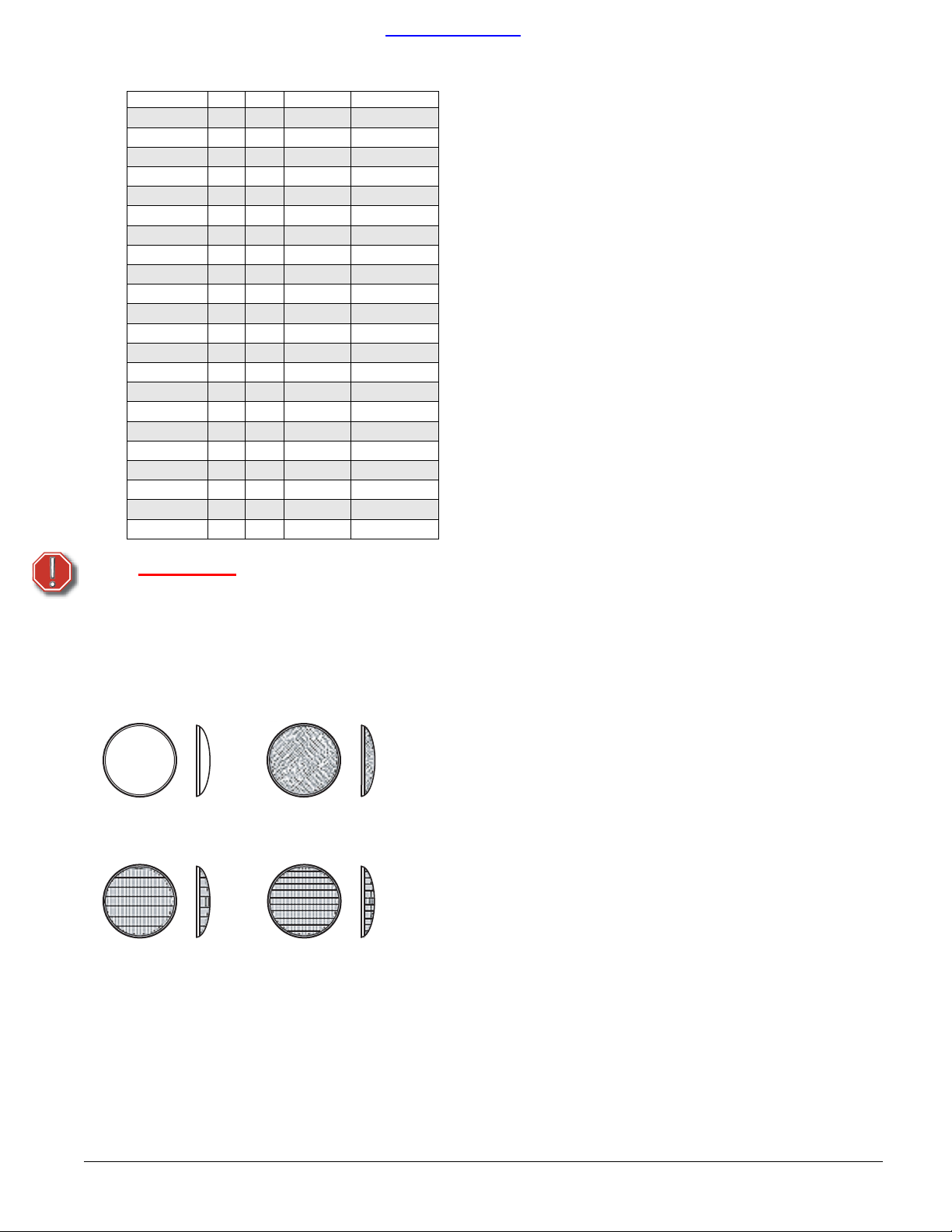
Lenses for the Source Four MultiPAR come in four versions. The type or beam
spread can be identified by the lens texture.
VNSP
Very narrow spot
Clear glass
15° Round beam shape
MFL
Medium flood
Fewer facets, sized 6 x 22mm
21° x 34° Oblong beam shape
NSP
Narrow spot
Stipple glass (slight diffuse texture)
19° Round beam shape
WFL
Wide flood
Many facets, sized 6 x 12mm
30° x 51° Oblong beam shape
Source Four MultiPAR • 3
Page 4
ORDER DIRECTLY TODAY AT: www.BulbAmerica.com or CALL TOLL FREE 888-505-2111
Accessories
ETC Part #
Color frame 7.5 in. sq./6.7 in. inside diameter) 7061A3047
Safety cable (31 in.) 7060A1022
C-clamp 7060A2009
Very Narrow Spot lens 7061A4002
Narrow Spot lens 7061A4003
Medium Flood lens 7061A4005
Wide Flood lens 7061A4006
Set of four Source Four PAR lenses
( V N S P, N S P, M F L , W F L )
7061A1013
Changing Source Four MultiPAR lenses
Removing a lens
1. Disconnect power from the fixture before attempting to remove or install a lens.
2. Source Four MultiPAR lenses become hot while in operation. Let the fixture cool
before handling the lens.
3. Place the fixture on a flat, stable work surface.
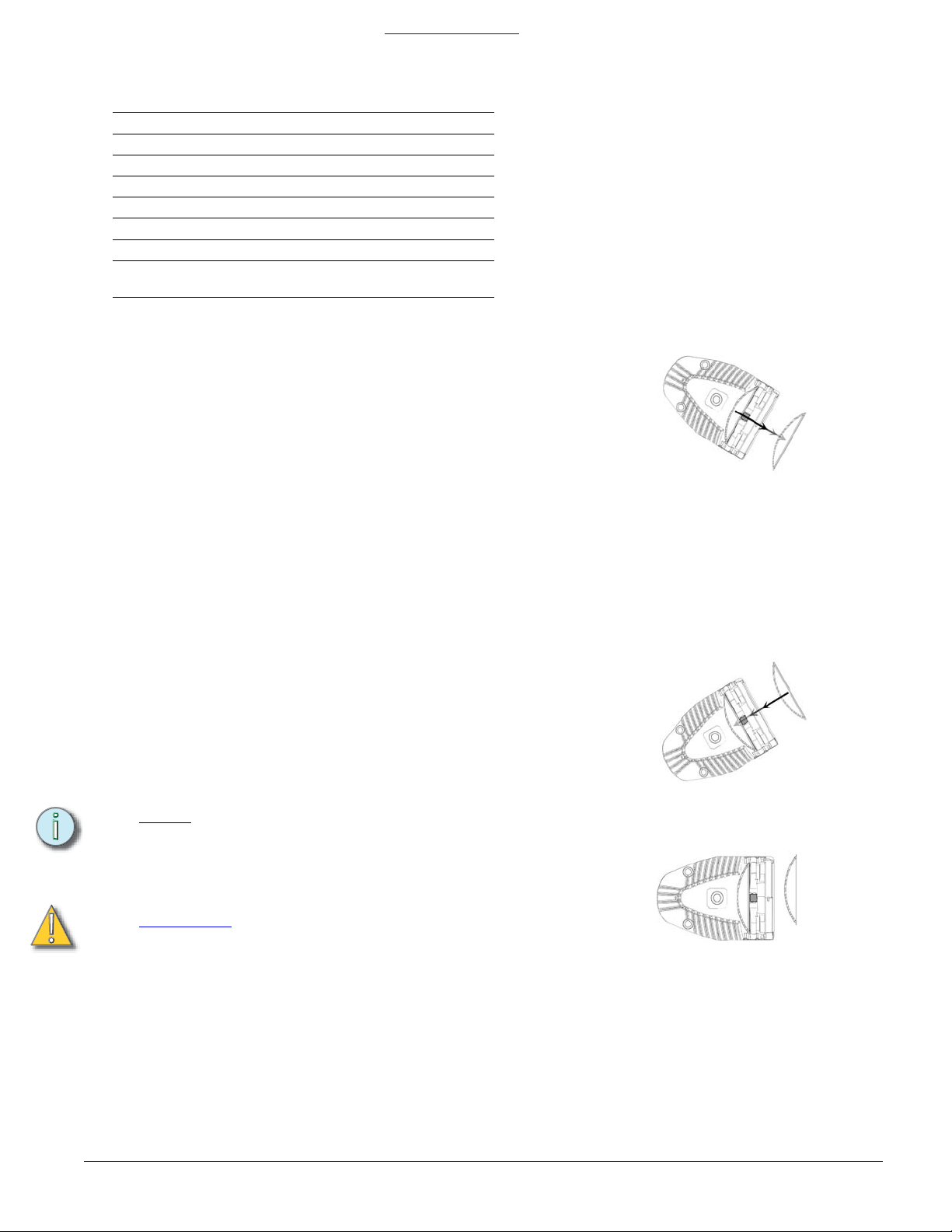
4. Tilt the front of the fixture down at least 45 degrees.
5. Press one (or both) of the spring clips with your finger(s) to release the lens.
Figure 2).
(
6. Allow the lens to drop forward from under the clip.
7. When the lens drops, remove your finger, maintain pressure on the clip while
sliding your finger(s) off the clip. Allow the lens to slide forward until you can grip
it securely.
8. Carefully remove the lens from the fixture.
Figure 2
Installing a lens
1. Position the fixture with the front of the unit (the lens side) facing you, and tilted
up slightly (
2. Hold the lens by the edge, and position it so the convex side faces the back of
the fixture Figure 4.
Note:
3. From the top of the fixture, slide the lens behind one of the lens clips and into the
cast metal lens channel.
4. Gently push the top of the lens inward until it snaps behind the other lens clip
CAUTION:
Figure 3).
Installing the lens with the convex side out will not impair the
optics, but it will make removing the lens more difficult.
Never operate the Source Four MultiPAR without a lens
in place.
Change lenses if they become cracked or badly
scr
atched.
Figure 3
Figure 4
4 • Source Four MultiPAR
Page 5
ORDER DIRECTLY TODAY AT: www.BulbAmerica.com or CALL TOLL FREE 888-505-2111
Gel frames and accessories
The MultiPAR does not use gel frame clips. However, both sides of the fixtures have
a bent sheet metal retainer to hold the gel frames in place. One side of the fixture
has a piece of spring steel that serves as a gel frame spring. The spring steel
pushes the gel frame into the MultiPAR. ETC identifies the side of the MultiPAR that
holds the gel frame as the gel frame retaining channel.
Note:
Use only color frames or accessories with 6.7” inside
diameter.
1. Insert the colorframe or accessory by pressing it against the spring. Figure 5
Once the edge of the frame has cleared the retaining channel, allow the edge of
2.
the frame to spring into the channel, thereby securing it.
3. Make certain the color frame is secured in the MultiPar opening by the spring clip
before operating.
Cleaning the reflector
1. Unplug the fixture before attempting to clean the reflector.
2. Remove the lamp before attempting to clean the reflector.
3. Remove the lens so you can access the reflector from the front of the fixture. See
Removing a lens on page 4.
4. Remove dust with a blast of oil free air, or wipe with a clean, soft, lint-free cotton
cloth. If this is sufficient to remove dust, go to step 7. Otherwise, continue to step
5.
5. Dampen a clean, soft, lint-free cotton cloth with a mild, soapy water solution and
gently wipe the reflector.
6. Remove any soapy water residue with a clean, soft, lint-free cotton cloth
dampened with water.
7. Reinstall a lens before using the fixture.
Figure 5
CAUTION:
Do not use glass or window cleaners on the reflector.
Chemicals in the cleaners
will harm the reflective
coating. Do not use paper towels or harsh materials to
wipe the reflector. These materials can scratch the
surface of the reflector.
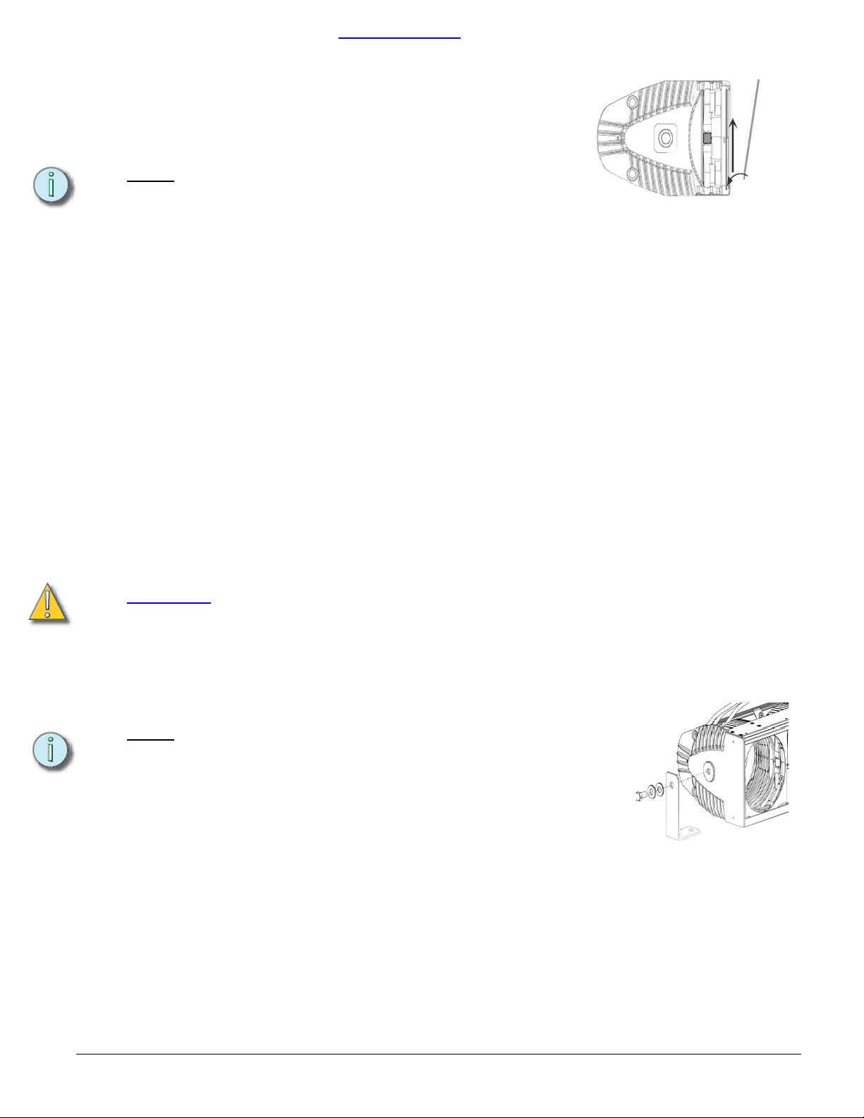
Adding hanging irons and c-clamps to MultiPAR
Note:
1. Loosen and remove the bolt and washer in the end casting.
2. Attach the hanging iron to the MultiPAR with the bolts and washers provided.
Figure 6 Be certain to attach the longer section of the hanging iron to the
MultiPAR and the shorter section to the c-clamp.
3. Make sure the smaller length of the hanging iron is secured over the MultiPAR
fixture body when attaching it to the unit.
4. The C-clamp attaches the fixture to the mounting pipe.
5. Tightly fasten the C-clamp to the yoke with the provided yoke bolt and lock
washer.
6. Place the C-clamp on mounting pipe, then tighten the pipe bolt to secure it.
7. Tighten the pan screw to lock the fixture into position.
The hanging irons attach to the MultiPAR. The c-clamp is
bolted to the other end of the hanging iron and then secured
to the hanging pipe.
Figure 6
Source Four MultiPAR • 5
Page 6
ORDER DIRECTLY TODAY AT: www.BulbAmerica.com or CALL TOLL FREE 888-505-2111
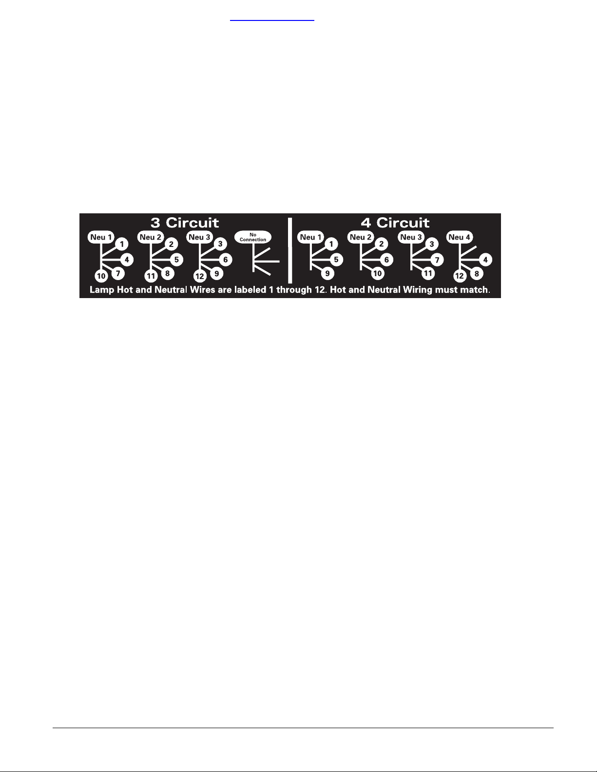
Circuit wiring configurations for the MultiPar-12.
The Source 4 MultiPAR can be wired for 3 circuit or 4 circuit configurations. Before changing the configuration, make
sure that you have sufficient power (dimmer capacity) to operate the fixture. There are four terminal blocks inside the
unit to place wiring. Each terminal block has four lead connection points. All of the hot and neutrals are labeled with
a number for your convenience.
Three circuit configuration
1. Disconnect power before changing the wiring.
2. Loosen the captured screw on the back of the raceway and open the raceway lid.
3. In the first terminal block on the left, insert the wires labeled 1,4,7,10.
4. In the second terminal block from the left, insert the wires labeled 2,5,8,11.
5. In the third terminal block from the left, insert the wires labeled 3,6,9,12
6. The fourth terminal block from the left is not used and is left empty.See Figure 7 for detail.
Figure 7
Four circuit configuration
1. Disconnect power before changing the wiring.
2. Loosen the captured screw on the back of the raceway and open the raceway lid.
3. In the first terminal block on the left, insert the wires labeled 1,5,9
4. In the second terminal block from the left, insert the wires labeled 2,6,10.
5. In the third terminal block from the left, insert the wires labeled 3,7,11.
6. In the fourth terminal block from the left, insert the wires labeled 4,8,12. See Figure 7 for detail.
6 • Source Four MultiPAR
Page 7
ORDER DIRECTLY TODAY AT: www.BulbAmerica.com or CALL TOLL FREE 888-505-2111
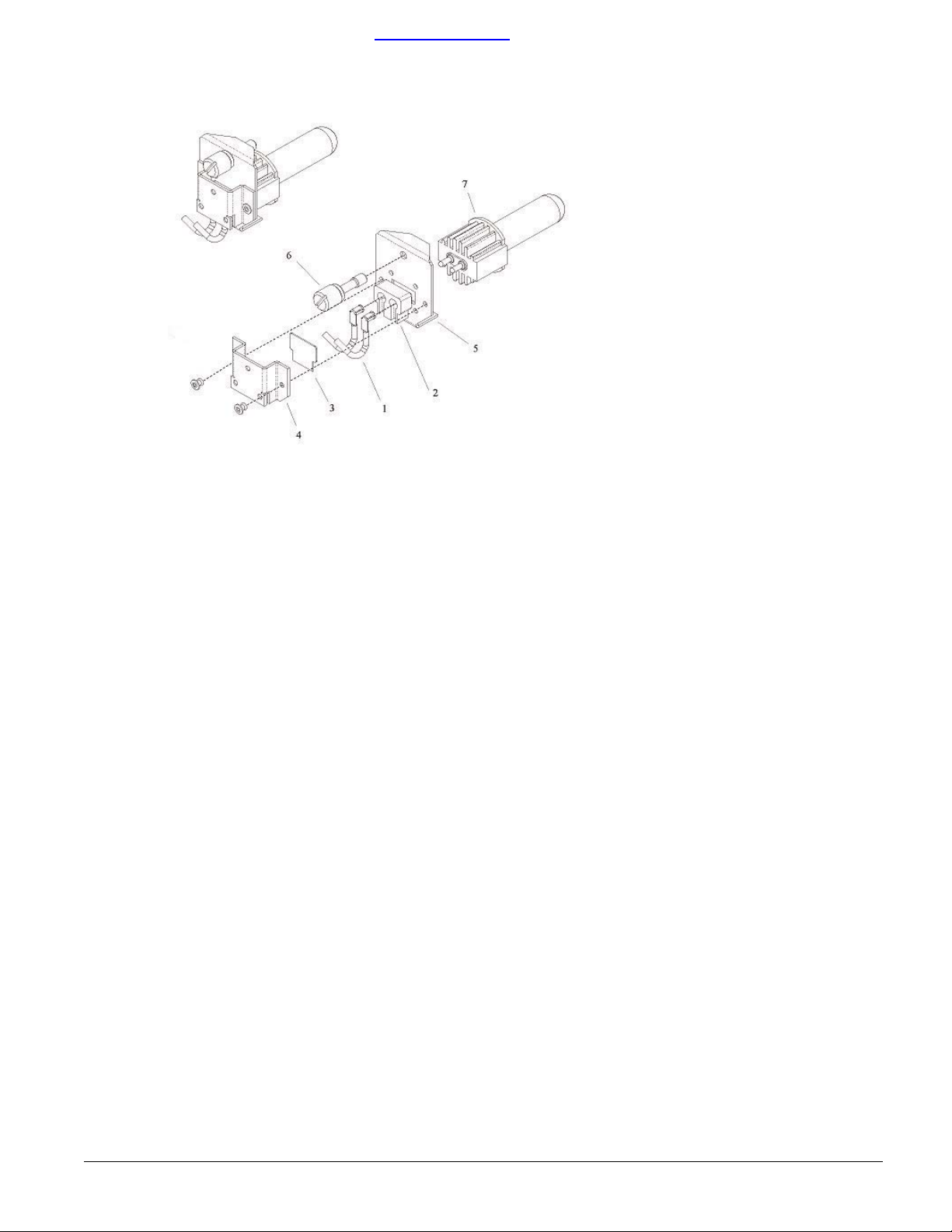
Spare parts list
Source Four MultiPAR Lamp Burner Assembly
Reference
Number
1 W330-01
2 W330-02
3 W330-03
1-6 7061A2027
1-6 7061A2028
1-6 7061A2029
6 7061A3061 Thumbscrew 1
7 various HPL lamp 1
Part Number Description
TP22 CLCLM assembly,
16-A
WG Wire, Silver
Contact, 3,5, or 7ft long
TP22 CLCM assembly,
amic
cer
TP22 CLCM assembly,
ca
mi
Lamp Burner Assembly
t
3f
Lamp Burner Assembly
5ft
Lamp Burner Assembly
7ft
Quantity
quired
Re
2
1
1
1
1
1
Source Four MultiPAR • 7
Page 8
ORDER DIRECTLY TODAY AT: www.BulbAmerica.com or CALL TOLL FREE 888-505-2111
Spare parts list
2
3
1
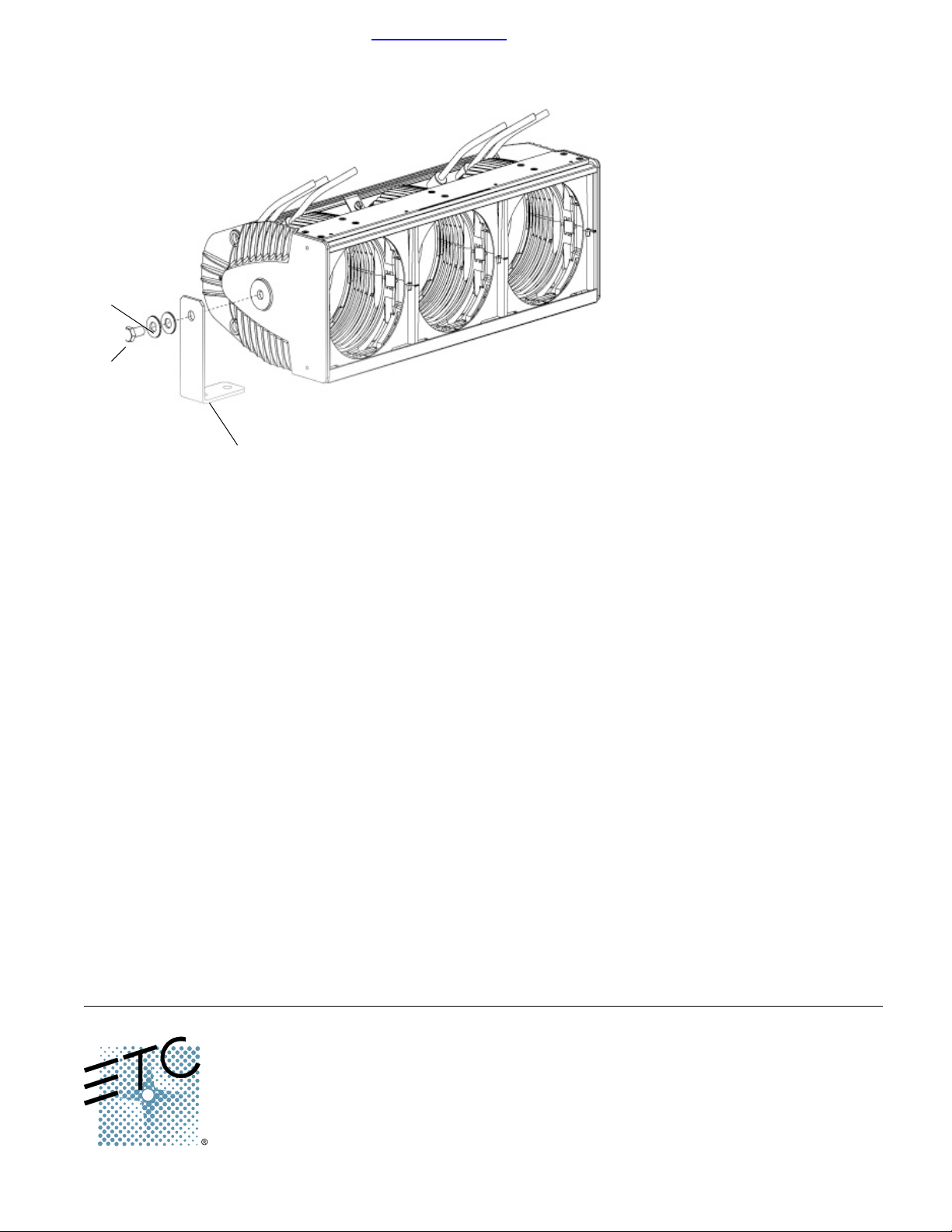
Source Four MultiPAR Final Assembly
Reference
Number
1 7061A3051 Hanger Bracket, MultiPar 2
2 HW587 1/2” washer 4
3 HW5138 1/2 -13 x 1” HH bolt 2
not pictured 7061A3050
Part Number Description
Trunnion Bracket, MultiPar
Quantity
Re
quired
2
Americas
3030 Laura Lane, P.O. Box 620979, Middleton, Wisconsin 53562-0979 USA Tel: +608 831 4116 +800 688 4116 Fax: +608 836 1736 +800 555 8912
Europe
Unit 4, Victoria Industrial Estate, Victoria Road, London W3 6UU, UK Tel: +44 (0)20 8896 1000 Fax: +44 (0)20 8896 2000
Asia
Room 605-606, Tower III Enterprise Square, 9 Sheung Yuet Road, Kowloon Bay, Kowloon, Hong Kong Tel: +852 2799 1220 Fax: +852 2799 9325
W
eb: www.etcconnect.com Email: (US) [email protected] (UK) [email protected] (Asia) [email protected]
Service: [email protected]
Copyright © 2002 Electronic Theatre Controls, Inc. All Rights Reserved. Product information and specifications subject to change.
7061M1014
Rev B Released 2/03
Toll free: 800 775 4382 Comments about this document: [email protected]
 Loading...