

Page 1

Source Four HID PAR™ CE User Guide
Page 2

DECLARATION OF CONFORMITY
We, Electronic Theatre Controls, Europe Limited
Unit 5, Victoria Industrial Estate, London W3 6UU United Kingdom declare under sole responsibility that
the product:
Product name: Source Four HID luminaires
Product type/model: 405HID, 410HID, 419HID, 426HID, 436HID, 450HID, 41530 HID, 42550
HID, 426HIDJ, 436HIDJ, 450HIDJ, 2550HIDJ, PAR-EAHID, PARNel HID
Lot: n/a
Batch / Serial number: n/a
Item numbers: one of each type
to which this declaration relates is in conformity with the following Standards:
EN60598-1:2000 Luminaires, General requirements and tests
EN60598-2-17:1990 Luminaires, Particular requirements, Specification for luminares for
stage lighting, television, film and photographic studios (outside and
indoor) - equiv. BS 4533-102.17:1990
BS EN 60922:1997 Auxileries for lamps. Ballasts for discharge lamps (excluding tubular flu-
orescent lamps). General and safety requirements.
Following the provisions of EU LV Directive(s) 73/23/EEC
EN55015:1996 Limits and methods of measurement of radio disturbance characteristics
of electrical ligthing and similar equipment.
EN61000-3-2:2001 Electromagnetic compatibility (EMC) Limits. Limits for harmonic current
emissions (equipmetn input current up to and including 16 A per phase) Class C
EN61000-3-2:1995 Electromagnetic compatibility (EMC) Limits. Limitation of voltage fluctua-
tions and flicker in low voltage supply systems for equipment with rated
current <= 16 A
London, United Kingdom
Adam Bennette
(Place of issue) (Name of authorised person)
13th December 200213th December 2002
(date of issue) (signature of authorized person)
Electronic Theatre Controls Europe Ltd. Registered office:
Unit 5, Victoria Industrial Estate, Grant Thornton House
Victoria Road, London W3 6UU U.K. Melton St., London, NW1 2BW, England
Page 3
English
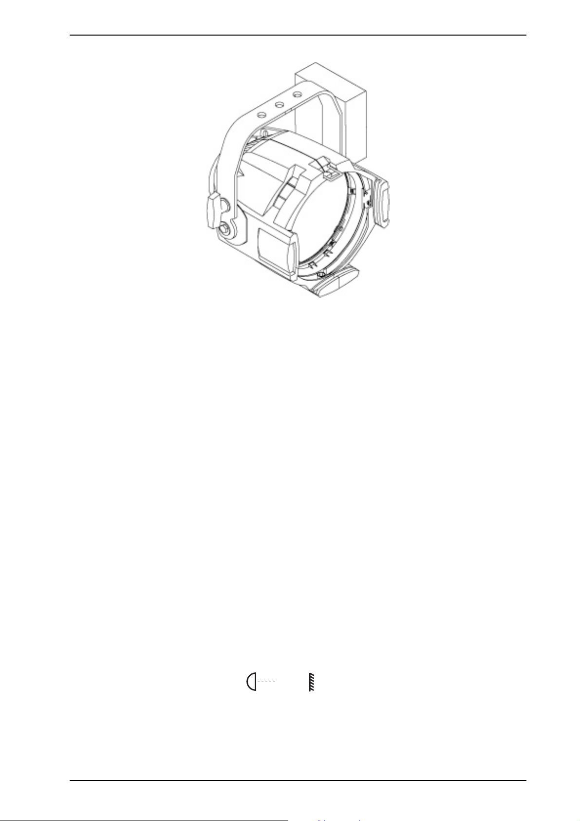
Source Four HID PAR CE guidelines
Please note the following precautions prior to use:
The Source Four HID PAR CE is intended for professional use only. Read the entire User Guide before using
equipment.
Please note the following safety precautions:
• The Source Four HID PAR CE is NOT dimmable. Dimming or regulated voltage will damage the ballast and void
the warranty.
• Do not mount the Source Four HID PAR CE on or near a flammable surface.
• Use the Source Four HID PAR CE in dry locations only, where humidity does not exceed 90 percent.
• The fixture is for indoor use only and is not intended for outdoor use.
• For temporary installations, mount and support the Source Four HID PAR CE only by the primary suspension yoke
holes. Suspend the fixture from a hook clamp or a stand mount, using a securely tightened steel bolt (up to Ø 12
mm), flat washer and locking washer.
• In addition to primary suspension, attach a safety cable (Model 400SC) or chain to the secondary suspension
point on the Source Four HID PAR CE.
• If the external cable is damaged, it shall be replaced by ETC or our service agents.
• Always hang the Source Four HID PAR CE with the colour frame held securely behind the PAR retaining channel.
• Always replace the lamp if it becomes damaged or thermally deformed.
• Lighted objects at this distance or greater will not exceed 90ºC temperature from projected light.
• Disconnect the unit from power before all cleaning and maintenance.
• The Source Four HID PAR CE is suitable for indoor use with a maximum ambient temperature: Ta=45°C
• Maximum exterior surface temperature: T
• A multilingual label sheet is included with this manual. Affix the label of the appropriate language over the existing
warning label on the extension yoke. Do not cover ETC trademark or CE mark.
• The Source Four HID PAR CE contains a CE safety screen that covers the lens in the event of accidental discharge. Do not remove the safety screen.
• Keep the luminaire at least 0.7 meters away from anything it is shining on.
max
=200ºC
0.7m
Source Four HID PAR CE 3
Page 4

English
Wiring and power information
A plug of at least 2.5 amp (220/240V) rating should be attached to the fixture’s mains lead. The wires in the mains
lead are 1.5mm2 each and coloured in accordance with the following code:
Green and Yellow:
Blue: Neutral
Brown: Live
Earth
WARNING: The CE Source Four HID PAR CE must be earthed.
Current rating: 240V/2.5 amp maximum
Operating frequency:
50/60Hz
Accessories
ETC Part #
Colour frame (19 cm sq./17 cm.inside diameter) 7061A3047
Safety cable (79 cm) 7061A1022
C-clamp 7060A2009
Top hat, 7.62 cm PSF1022
Top hat, 15.24 cm PSF1023
Half hat PSF1027
Cross-baffle top hat PSF1031
Egg-crate louver PSF1028
Weighted base PSF1032
Gel Extender 7.62 cm PSF1030
Gel Extender 15.24 cm PSF1029
Barn door PSF1019
t 180°c
HID Lamp type and general information:
Do not use lamps other than the following types in the Source Four HID PAR CE. Use of lamps other than specified below will void CE safety compliance and your warranty.
Lamp Type Manufacturing Codes Watts Base Bulb LCL Ave.
CDM-T 150W/830 150 G12 T6 56mm 9000 14000 3000°K
Ceramic
Metal
Halide
CDM-T 150W/942 150 G12 T6 56mm 9000 12700 4000°K
MD150T6/U/G12/
830
MBI150/T/30 150 G12 T7 57mm 6000 11500 3000°K
MBI150/T/40 150 G12 T7 57mm 6000 11250 4000°K
150 G12 T6 56mm 9000 14000 3000°K
Hrs.
Initial
lumens
Color
temp
4 Source Four HID PAR CE
Page 5
Installing the lamp
1. Disconnect power to the Source Four HID PAR CE before installing the lamp.
2. Loosen the knurled bolt on the back of the lamp housing and pull the housing out.
3. Holding it by the base, remove the lamp from its box.
English
Note:
To avoid premature lamp failure, do not touch the lamp glass with your fingers. If you
touch the lamp during installation, clean it carefully with rubbing alcohol and a clean, lintfree cloth before operation.
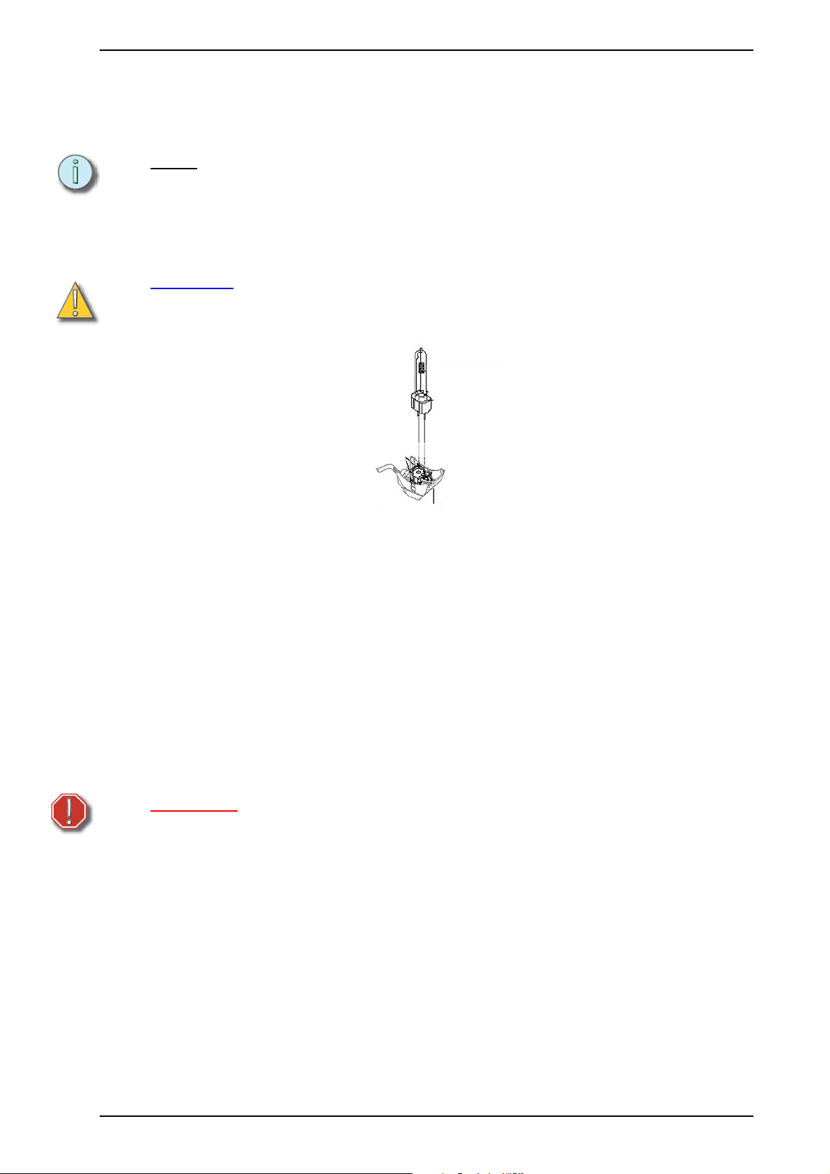
4. Insert lamp base into socket assembly. (Figure 1)
5. Push down on the lamp base until the lamp seats firmly.
6. Reinstall the lamp housing by aligning the bolt hole and tightening the knurled bolt.
CAUTION:
Replace the lamp if it becomes damaged or thermally deformed.
Improperly installed lamps will cause premature lamp and socket
failures.
Figure 1
Ballast information
• The only acceptable voltage is 120V (+/- 10%) 50/60HZ.
• The standard operating current is 1.5 Amps.
• The standard inrush current is <14 Amps.
• Room ambient temperature should not exceed 40ºC.
• The lamp ignition voltage is 4.5Kv, non-hot restrike.
• The ballast case temperature should not exceed 75ºC.
• The ballast is attached to the Source Four yoke by two screws and is non-removable.
WARNING: DO NOT power the Source Four HID PAR CE with a dimmable power supply.
Dimming will damage the ballast and void the warranty.
Source Four HID PAR CE 5
Page 6
English
Lens identification
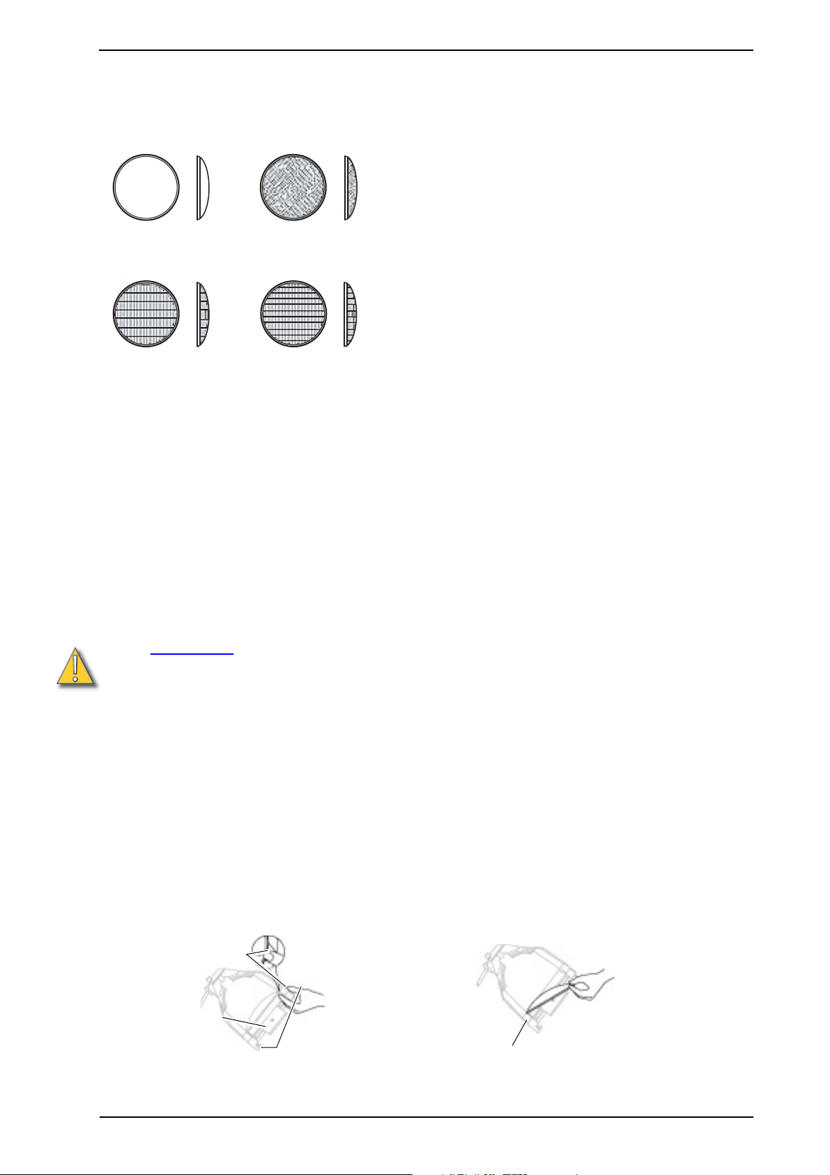
Lenses for the Source Four HID PAR CE come in four versions. The type or beam spread can be identified by the
lens texture.
VNSP
Very narrow spot
Clear glass
15° Round beam shape
MFL
Medium flood
Fewer facets, sized 6 x 22mm
21° x 34° Oblong beam shape
NSP
Narrow spot
Stipple glass (slight diffuse texture)
19° Round beam shape
WFL
Wide flood
Many facets, sized 6 x 12mm
30° x 51° Oblong beam shape
Changing Source Four HID PAR CE lenses
Change lenses if they become cracked or badly scratched.
CAUTION:
Removing a lens
1. Disconnect power to the fixture before handling.
2. Place the fixture on a flat, stable work surface. Do not install or remove lenses with the unit hanging.
3. Position the lens rotation ring with the spring clip at the top of the unit, directly below the retaining clip.
4. Tilt the front of the fixture down at least 45 degrees.
5. Press the spring clip with your finger to release the lens (Figure 2).
6. Allow the lens to drop forward from under the clip.
7. When the lens drops, remove your finger, allowing the lens to slide forward until it rests on the lens catchers
(Figure 3).
8. Carefully remove the lens from the fixture.
Spring clip
Never operate the Source Four HID PAR CE without a lens in place.
Source Four HID PAR CE lenses get hot while the unit is in operation.
Let the fixture cool before handling the lens
Tab
Retaining clip
6 Source Four HID PAR CE
Figure 2
Lens
catcher
Figure 3
Page 7
Installing a lens
n
1. Disconnect power to the fixture before handling.
2. Position the fixture with the front of the unit (the lens side) facing you, and tilted slightly (Figure 2).
3. Position the lens rotation ring with the spring clip at the top of the fixture, directly below the color frame
retaining clip.
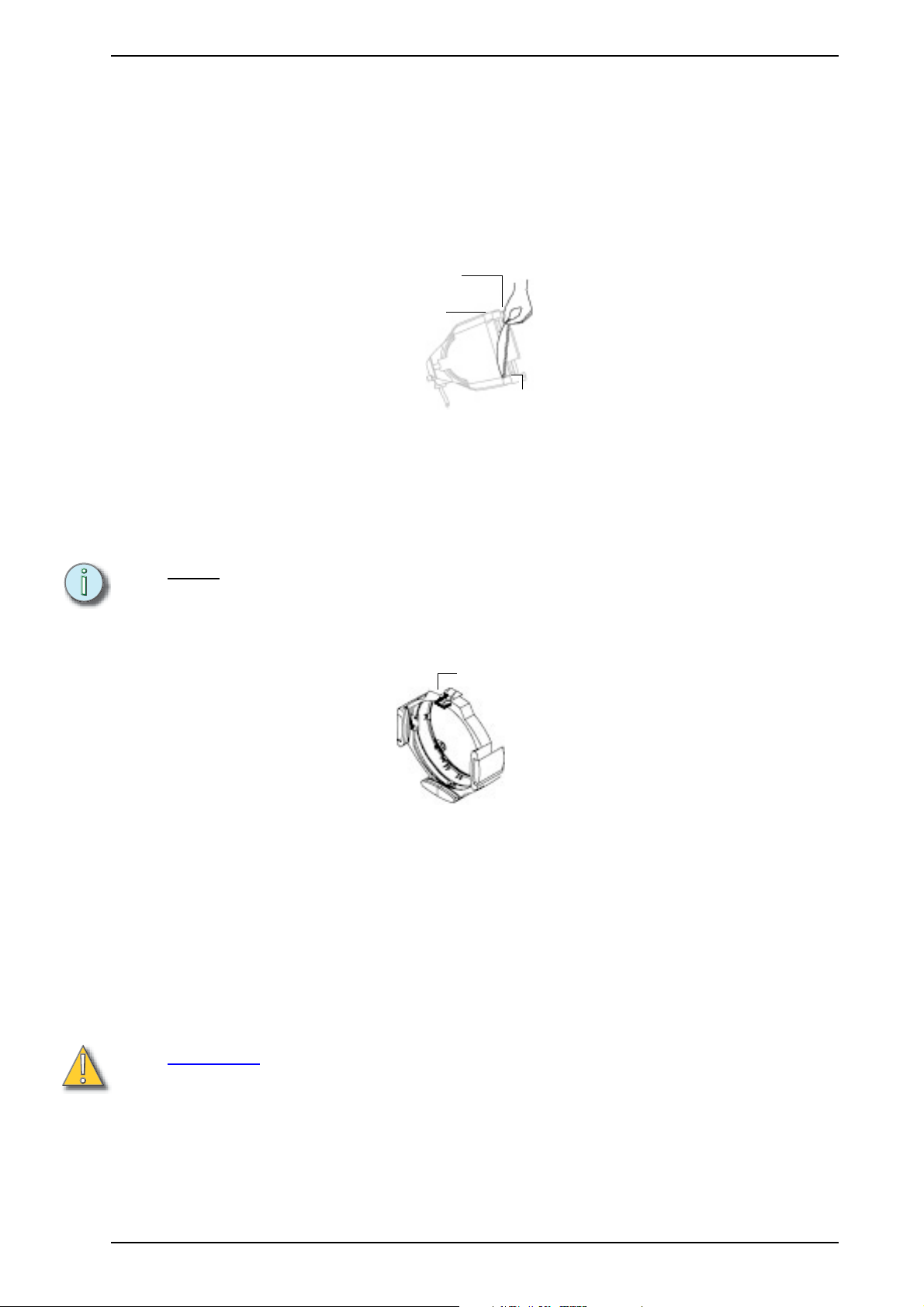
4. Hold the lens by the edge, and position it so the convex side faces the back of the fixture (Figure 4).
5. From the top of the fixture, slide the lens behind the lens catchers and position its base behind the tabs on the
bottom of the lens rotation ring.
6. Gently push the top of the lens inward until it snaps behind the spring clip.
Retaining clip
Spring clip
Tab
Figure 4
Colour frame retaining clip usage
English
The colour frame holder is equipped with a spring-loaded retaining clip that prevents colour frames and accessories from falling out. Make sure the Source Four HID PAR CE has the colour frame retaining clip in the locked
position when hanging.
Note:
1. Release the retaining clip by pushing it sideways. The retaining clip opens.
2. Insert the colour frame.
3. Press the retaining clip down until it locks.
Make sure to use colourframes or accessories with a 17 cm inside diameter.
Retaining clip in
the locked positio
Figure 5
Cleaning the reflector
1. Unplug the fixture before attempting to clean the reflector.
2. Remove the lamp before attempting to clean the reflector.
3. Remove the lens so you can access the reflector from the front of the fixture. (See Removing a lens on page 6)
4. Remove dust with a blast of oil free air, or wipe with a clean, soft, lint-free cotton cloth. If this is sufficient to
remove dust, go to step 7. Otherwise, continue to step 5.
5. Dampen a clean, soft, lint-free cotton cloth with a mild, soapy water solution and gently wipe the reflector.
6. Remove any soapy water residue with a clean, soft, lint-free cotton cloth dampened with water.
7. Reinstall a lens before using the fixture.
CAUTION:
Do not use glass or window cleaners on the reflector. Chemicals in the cleaners
will harm the reflective coating. Do not use paper towels or harsh materials to wipe
the reflector. These materials can scratch the surface of the reflector.
Source Four HID PAR CE 7
Page 8

English
Housing assembly instructions
If you take apart the Source Four HID PAR CE for any reason, please use the following steps for reassembly.
Improper reassembly will result in void of warranty and loss of performance.
Tools required: Phillips and flat head screwdrivers, rubber mallet, channel locks, pliers or crescent wrench.
1. Install the clutch plate (13) onto the left housing (3) and secure with nut (14). The right housing has three screw
holes on its side, and one hole for the yoke bolt. The left housing only has two bolt holes, for the yoke.
2. Install the four reflector mount pads (4) in the right (2) and left (3) housing. There are two recessed places in
each housing for the pads.
3. Insert the spring clip (10), with the open end facing the lamp, into the lens rotation ring (8). Place a flathead
screwdriver in the spring clip slot and gently tap with a rubber mallet. Using your finger, press the clip down (as
if to close it) until it snaps into place over the tab, inside the rotating ring.
4. Place the left housing on a flat surface with the lens end pointing to the right. Install the lens rotation ring (8)
into the left housing (3).
5. Install the rotator pressure clip (12) into the left housing (3) with screw (9), and tighten firmly.
6. Place the spring (7) on the long end of the gel retainer clip (6) and insert the short end into the left housing (2).
7. Install the reflector (1) into the left housing (3). The reflector must be seated securely on the reflector mount
pads, behind the ridge.
8. Position the reflector with the single orientation tab on the bottom, and fit it into the single slot on the base of
the left housing. The edge of the reflector mount pads should be visible.
9. Pull the reflector tight against the edge of the housing. (Hint: This is easier if you hold the left housing with your
left hand and put your left index finger through the hole on the back of the reflector.) Make sure the reflector is
seated firmly (the orange pads should be visible).
10. Attach the right housing (2) to the left housing (3) using the three .6350 cm x 1.9cm screws (5). Make certain
the gel retainer clip is in place.
11. Check for ease of movement of the gel retainer clip (6). The clip should latch into the left housing in the down
position and not bind. If it is tight, work several times to loosen using channel locks, pliers or wrench.
12. Verify that the lens rotation ring rotates smoothly, but does not spin loosely.
13. Snap the focus knob plug (11) into the bottom of the fixture assembly, as shown in the Source Four HID PAR
CE Housing Assembly diagram on page 6.
8 Source Four HID PAR CE
Page 9
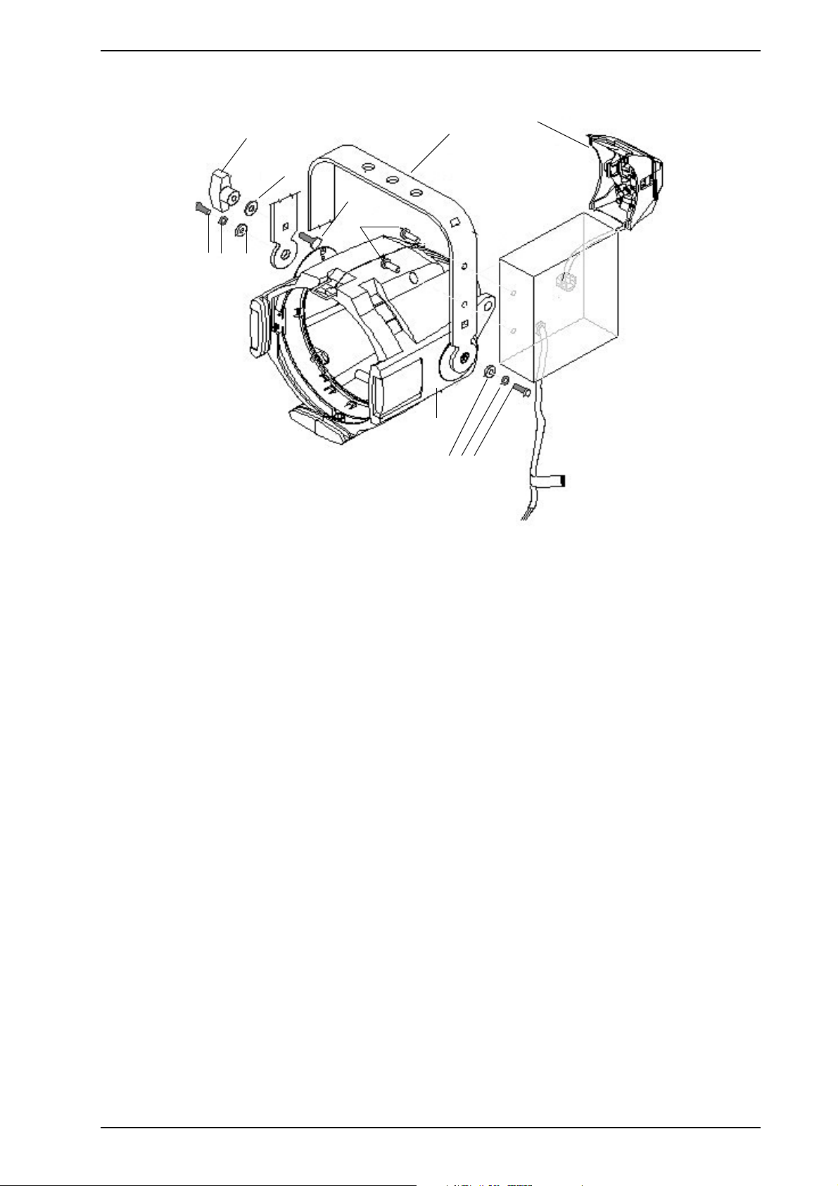
Spare parts list
English
13,14
10 9 12
5,6
3,4
8
7
11
1,2
12 9 10
Source Four HID PAR CE Final Assembly
Reference
Number
1 7061A2022
2 7061A2022-1
3 7061A2203-0X
4 7061A2203-1X
5 7061A3039
6 7061A3039-1
7 HW5125 Bolt, carriage 1
8 HW5126 Washer, flat 1
9 HW5139 Washer, split ring lock 2
10 HW5172 Bolt, hex 2
11 HW5270 Bolt, spinlock 2
12 HW522 Washer, flat 2
13 HW8144
14 HW8144-1
Part Number Description
S4 HID PAR base
assembly (black)
S4 HID PAR base
assembly (white)
CE HID PAR Lamp
socket assembly (black)
CE HID PAR Lamp
socket assembly (white)
HID PAR yoke bracket
(black)
HID PAR yoke bracket
(white)
Handle, yoke knob
(black)
Handle, yoke knob
(white)
Quantity
Required
1
1
1
1
1
1
1
1
Source Four HID PAR CE 9
Page 10
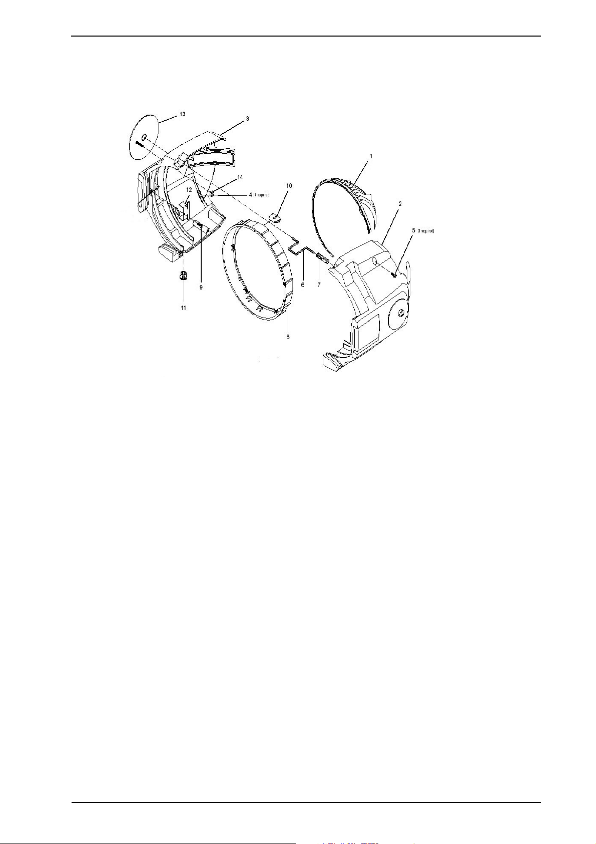
English
Spare parts list
Source Four HID PAR CE Housing Assembly
Reference
Number
1 7061A3014 Reflector, EA painted 1
2 7061A3025 Housing, right, PAR, painted 1
3 7061A3026 Housing, left, PAR, painted 1
4 7061A4001 Pad, silicon, reflector mount 4
5 HW391
6 7061A3005 Clip, gel retainer 1
7 HW750 Spring retainer 1
8 7060A4012 Lens rotation ring 1
9 HW3106
10 7061A3013 Spring clip, rotator 1
11 HW6128 Plug, focus knob 1
12 7061A3029 Rotator pressure clip 1
13 7061A3031 Clutch plate, black anodized 1
14 HW402 Nut, .8 cm 1
not pictured 7061A1030 Source 4 Par safety screen 1
Part Number Description
Screw, .6350cmx1.9 cm PhPHMS, black
zinc
Screw, .6350 cmx.6350 PhFIMS, black
zinc
Quantity
Required
3
1
10 Source Four HID PAR CE
Page 11

English
This page intentionally blank
Source Four HID PAR CE 11
Page 12

Americas
3030 Laura Lane, P.O. Box 620979, Middleton, Wisconsin 53562-0979 USA Tel: +608 831 4116 +800 688 4116
Fax: +608 836 1736 +800 555 8912
Europe
Unit 4, Victoria Industrial Estate, Victoria Road, London W3 6UU, UK Tel: +44 (0)20 8896 1000 Fax: +44 (0)20 8896 2000
Asia
Room 605-606, Tower III Enterprise Square, 9 Sheung Yuet Road, Kowloon Bay, Kowloon, Hong Kong Tel: +852 2799 1220 Fax: +852 2799 9325
W
eb: www.etcconnect.com Email: (US) [email protected] (UK) [email protected] (Asia) [email protected]
Service: [email protected]
Toll free: 800 775 4382 Comments about this document: [email protected]
Copyright © 2003 Electronic Theatre Controls, Inc. All Rights Reserved. Product information and specifications subject to change.
7061M1015
Rev A Released 4/03
 Loading...