

Page 1
Step 3
Step 2
SmartStand
Setup and Connect Guide
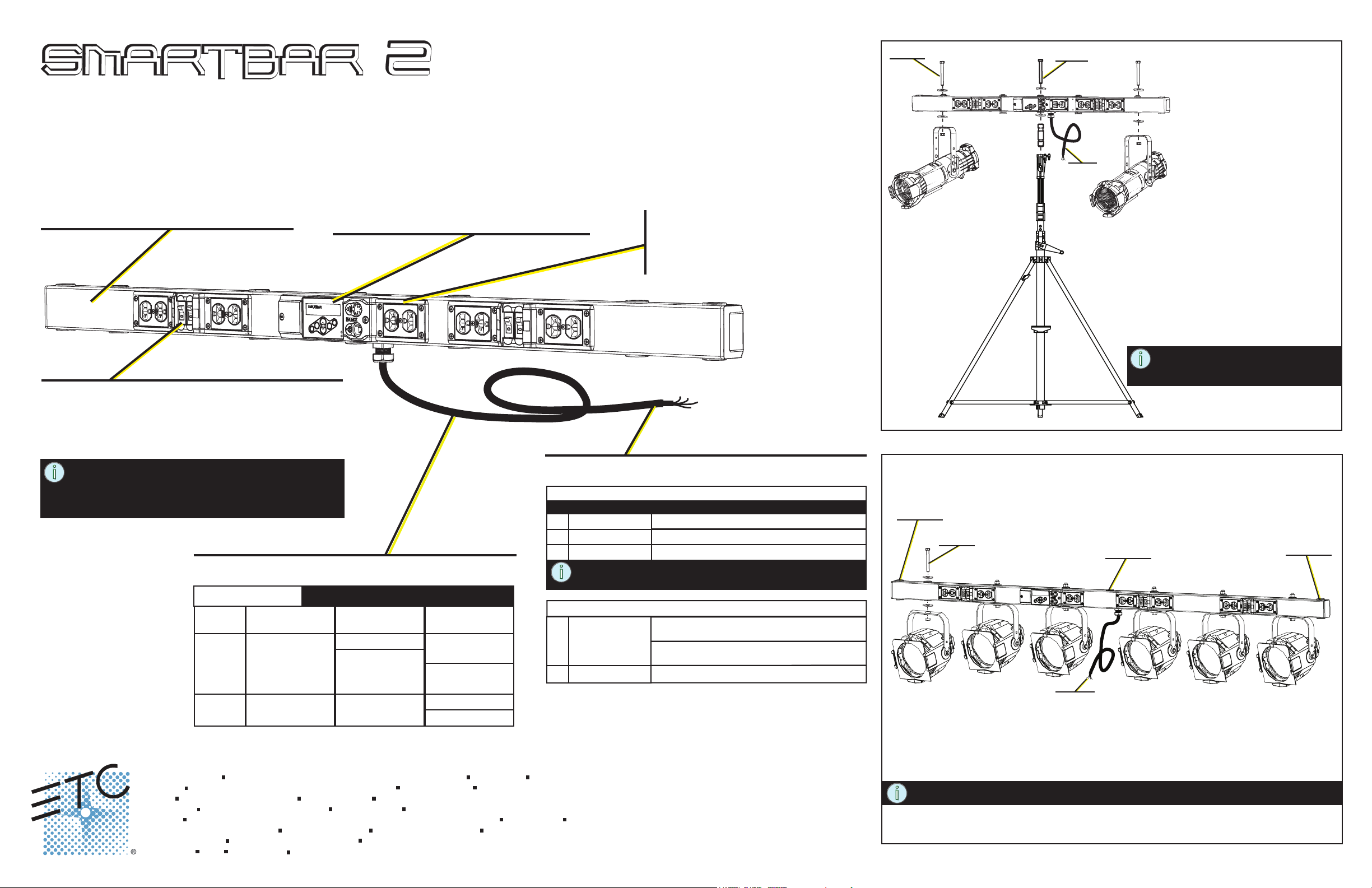
SmartBar2
2, 4 or 6 channel bars
DMX 512 compliant
RDM identify / RDM - DMX Address
UL / cUL Listed and CE Marked
Dimmers and Circuit Breakers
10 Amp dimmer per channel output with magnetic
circuit breaker (load protection).
Choice of output connectors
“Smart” User Interface
Local manual control of dimmers and 20
built-in chases for stand-alone operation
Multi-language software including English,
Spanish, German and French
DMX 512 In and Thru XLR connectors
Convenience Outlets
UL outlet type is dual Edison
CE outlet type typically matches
the output connector type.
Mounting
Step 1
Step 1: Install the input connector.
Step 2: Attach the SmartBar2 to the
SmartStand using the stand adaptor
kit and hardware provided. Be sure to
tighten the set screw on the stand
adaptor for a snug fit.
Step 3: Secure each fixture to the SmartBar2
using the hardware provided. Each
bolt kit contains two washers. Install
one on top and one on bottom.
NOTE: Reference the SmartStand
documentation for weight
restrictions.
NOTE: Total load output cannot exceed capacity of
the mains power input. Many supply breakers
have an 80% rating. 75 Watts minimum load
per dimmer for best results.
Mains Power Specification
Mains Power Input (Do Not exceed 20A maximum per phase)
2 channel 4 channel 6 channel
UL / cUL
CE
Corporate Headquarters
London, UK
Rome, IT
Holzkirchen, DE
Hong Kong
Service:
Web:
7543M1300-2.0.0
Unit 26-28, Victoria Industrial Estate, Victoria Road, London W3 6UU, UK Tel +44 (0)20 8896 1000 Fax +44 (0)20 8896 2000
Via Pieve Torina, 48, 00156 Rome, Italy Tel +39 (06) 32 111 683 Fax +44 (0) 20 8752 8486
Ohmstrasse 3, 83607 Holzkirchen, Germany Tel +49 (80 24) 47 00-0 Fax +49 (80 24) 47 00-3 00
Rm 1801, 18/F, Tower 1 Phase 1, Enterprise Square, 9 Sheung Yuet Road, Kowloon Bay, Kowloon, Hong Kong Tel +852 2799 1220 Fax +852 2799 9325
(Americas) service@etcconnect.com (UK) service@etceurope.com (DE) techserv-hoki@etcconnect.com (Asia) service@etcasia.com
www.etcconnect.com
Rev B Released 2012-07 ETC intends this document to be provided in its entirety.
1Ø - 100, 120 VAC 1Ø 100, 120 VAC 2Ø 120/240 VAC
1Ø 230 VAC 1Ø 230 VAC 1Ø 230 VAC
3031 Pleasant View Road, P.O. Box 620979, Middleton, Wisconsin 53562-0979 USA Tel +608 831 4116 Fax +608 836 1736
Copyright © 2012 ETC. All Rights Reserved.
2Ø 120/240 VAC
100/200 VAC
Product information and specifications subject to change.
100/200 VAC
3Ø 120/208 VAC
100/173 VAC
3Ø 230/400 VAC
Input connector is not supplied.
Recommended (UL) Input Connector
To maintain UL Listing, use a recommended input connector.
1Ø
2 wire + ground
2Ø
3 wire + ground
4 wire + ground
3Ø
NOTE: Using a NEMA L5-15, 5-15 or 14-15 input connector
derates the SmartBar2 to 15A maximum input.
Recommended (CE 230 VAC) Input Connector
1Ø
2 wire + ground
4 wire + ground
3Ø
use NEMA L5-15, 5-15, L5-20, 5-20
use NEMA 14-15, 14-20, L14-20
use NEMA 21-20
dual NF or dual Shuko load connectors use
Schuko or NF male 16A
UK15A Round Pin load connectors use
UK15A Round Pin male or CE17 16A
CE17 male 16A 3PNE
Page 1 of 2
Optional Mounting
optional
mounting
Step 2
Step 1
Step 1: Install the input connector.
Step 2: Secure each fixture to the SmartBar2 using the hardware provided. Each bolt kit contains
two washers. Install one washer on top and one on bottom of the unit.
NOTE: Through-holes are provided on the bar for optional mounting.
optional
mounting
optional
mounting
Page 2
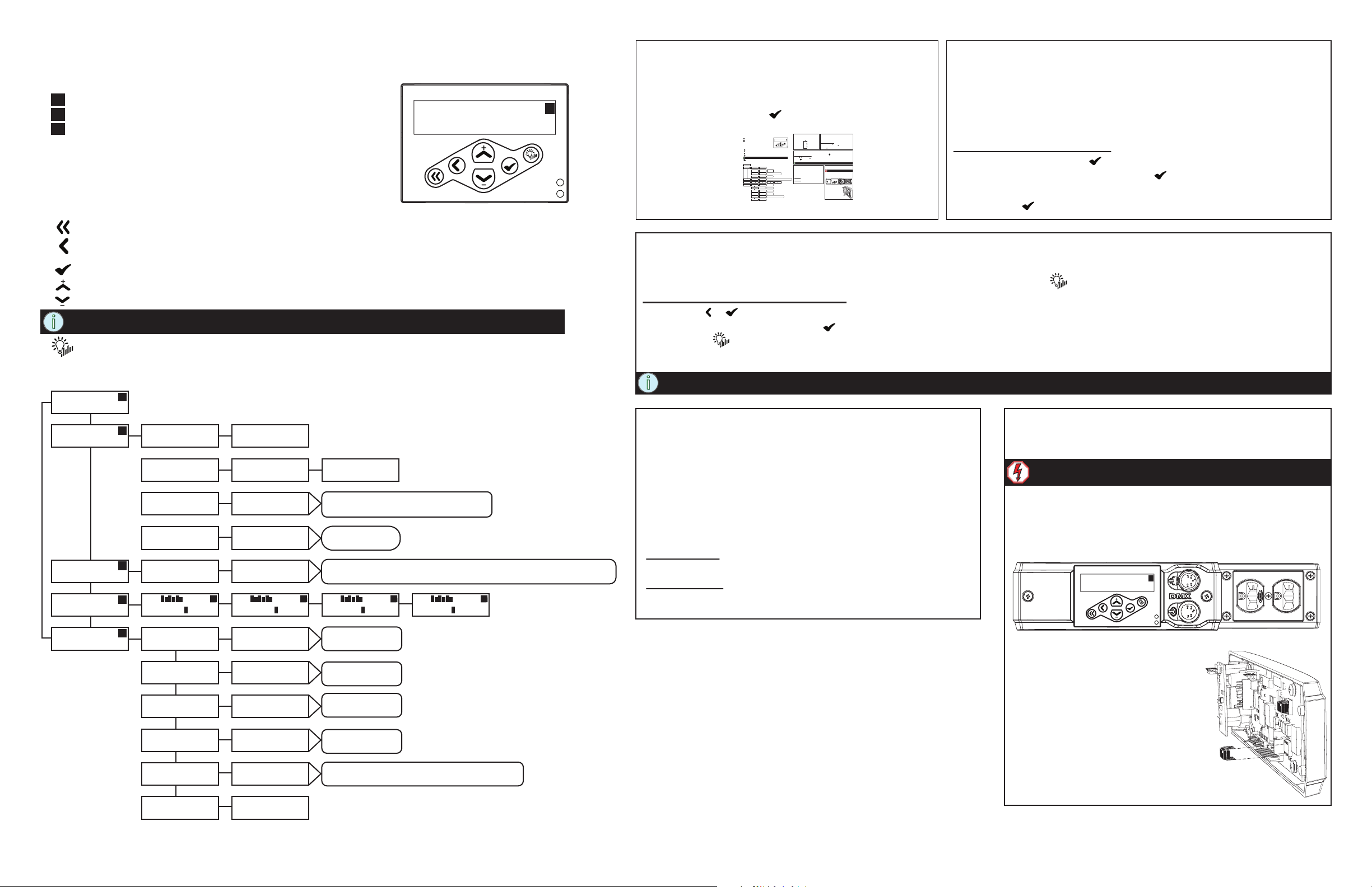
User Interface
The SmartBar2 user interface and menu structure provide users an intuitive easy setup with multiple
language options built-in.
d = DMX
T = Test
C = Chase
The two LEDs on the user interface indicate power and DMX signal. When
power is applied, the blue “Power” LED is illuminated. The green LED
indicates DMX signal. When no DMX signal is present, the green LED will
flash. When a stable DMX signal is present, the green LED will illuminate fully.
Keypad
returns to the home menu
cancels the current operation and returns to the previous
menu or selection
activates a menu selection or stores a value
pressing once increases a value or menu choice by one.
pressing once decreases a value or menu choice by one.
NOTE: “+” and “-” values auto repeat with acceleration when pressed and held for two
seconds.
enters “Test Mode” from any menu. Exiting test returns to the previous menu.
DMX: 123 > 128
Level:
ETC
[DMX ]
ETC
[Dimmer Cu rves]
ETC
[Chase]
The indicator located in the top right hand corner
of the LCD indicates the current control source.
d
d
d
d
Menu Flow Chart
DMX
[DMX St art Addre ss]
DMX
[DMX Patc h]
DMX
[DMX los s behavior]
DMX
[DMX Mo de]
Dimmer Num: [12]
Fluoresc ent
CH: Enabled
[01] T: 00.0 Yes
DMX Star t Address
DMX: [501 - > 506]
DMX Patch
Dim [12] > DMX 512
DMX loss b ehavior
[Wait and Fad e]
DMX Mode
[Start A ddress]
Dimmer Num: 12
[Fluores cent]
CH: Enabled
C
01 T: [00.0] Yes
C
DMX: 001 > 006
d
Level: 25
DMX Patch
Dim 12 > DMX [512]
options inc lude Hold L ast Look. W hen set to Wait
and Fade, “ Wait Time: [mm:ss] d isplays for se lection.
options inc lude:
DMX Patch
options inc lude Linear, Sw itche d (non-di m), and Pre- Heat. Set S tart Voltag e displays
when Fluores cent is the sele ction. Set Pr e-He at Level displays wh en Pre-H eat is the sele ction
CH: Enabled
01 T: 00.0 Yes
CH: Enabled
C
01 T: 00.0 [Yes]
C
First Time Power-up Display
The first time you apply power to the unit, you will be
asked to choose a language for the operating system.
The language options will cycle through at three
second intervals. Press to set the displayed
language option.
User Interface
The SmartBar2 user interface and menu structure provide users an intuitive easy setup with multiple
language options built-in.
d = DMX
The indicator located in the top right hand corner
DMX: 001 > 006
T = Test
of the LCD indicates the current control source.
Level: 25
C = Chase
The two LEDs on the user interface indicate power and DMX signal. When
power is applied, the blue “Power” LED is illuminated. The green LED
indicates DMX signal. When no DMX signal is present, the green LED will
flash. When a stable DMX signal is present, the green LED will illuminate fully.
Keypad
returns to the home menu
cancels the current operation and returns to the previous
menu or selection
activates a menu selection or stores a value
pressing once increases a value or menu choice by one.
pressing once decreases a value or menu choice by one.
NOTE: “+” and “-” values auto repeat with acceleration when pressed and held for two
seconds.
enters “Test Mode” from any menu. Exiting test returns to the previous menu.
DMX: 123 > 128
d
Menu Flow Chart
Level:
DMX
ETC
DMX Start Address
d
[DMX Start Address]
[DMX]
DMX: [501 -> 506]
DMX
DMX Patch
DMX Patch
[DMX Patch]
Dim [12] > DMX 512
Dim 12 > DMX [512]
DMX
DMX loss behavior
options include Hold Last Look. When set to Wait
and Fade, “Wait Time: [mm:ss] displays for selection.
[DMX loss behavior]
[Wait and Fade]
DMX Mode
DMX
options include:
DMX Patch
[Start Address]
[DMX Mode]
Dimmer Num: 12
Dimmer Num: [12]
ETC
options include Linear, Non-dim (relay), and Pre-Heat. Set Start Voltage displays
d
when Fluorescent is the selection. Set Pre-Heat Level displays when Pre-Heat is the selection
[Fluorescent]
Fluorescent
[Dimmer Curves]
CH: Enabled
CH: Enabled
CH: Enabled
ETC
CH: Enabled
CCC
d
01 T: 00.0 Yes
01 T: [00.0] Yes
[01] T: 00.0 Yes
[Chase]
01 T: 00.0 [Yes]
options include:
General Settings
Set Language
ETC
d
Francais, Deutsch, Espanol
[Set Language]
[English]
[General Settings]
LCD Backlight
General Settings
options include:
Off, Auto
[On]
[LCD Backlight]
options include:
Menu Mode
General Settings
Advanced Menu
[Normal Menu]
[Menu Mode]
Are you Sure?
General Settings
options include:
Yes
[No]
[Restore Defaults]
Are you Sure?
General Settings
option includes Yes.
Sets all curves to Mod Sqr Law, Base Address 1, Erases DMX Patch
[No]
[Deep Clear System]
Software Version
General Settings
v2.#.#
[Software Version]
First Time Power-up Display
The first time you apply power to the unit, you will be
asked to choose a language for the operating system.
The language options will cycle through at three
d
second intervals. Press to set the displayed
language option.
Set Language - English
Choisir la langue - Français
Sprache auswählen - Deutsch
Seleccionar idioma - Español
Test Menu
The test menu is a tool for testing dimmers and loads. In the absence of a DMX control source, the test menu may also be used to
set dimmer levels. Enter test mode from any menu by pressing the test button .
Set dimmer levels in the test menu
Step 1: Use or to select one or [All] dimmers.
Step 2: Use + or - to set a level, press . The menu will progress to the next channel.
Step 3: Press “Exit Test Mode [Keep Test On]” displays. Options are, [Keep Test On]
which exits with test levels still active, [Test: All Off] which releases test levels then
exits Test Mode.
NOTE: Press << to return to the main menu and clear all test levels.
DMX 512
DMX may be daisy chained from one unit to another utilizing
the XLR connectors on the front of the unit. The DMX-Thru
connector is self-terminated if no XLR connection is inserted.
RDM
RDM features of the SmartBar2 are available to RDM controllers with standard DMX cabling as described in the DMX
section above.
RDM Identify - when this command is sent from a RDM
controller, the LCD display of the SmartBar2 will flash.
DMX Address - displays the DMX address and allows
C
addressing to be changed from any RDM controller.
Page 2 of 2
Normal Menu
The normal menu is used to view system status and to set the DMX
start address for the unit. The start address range is determined by the
size of the unit but limited to DMX address 512. A two channel unit has
a range of 001 - 511, a 4 channel unit has a range of 001 - 509, and
the 6 channel unit has a range of 001 - 507.
Set the DMX Start Address
Step 1: Scroll to DMX, press .
Step 2: Scroll to DMX Start Address, press .
Step 3: Use + or - to scroll the start address range.
Step 4: Press to set the start address.
Replace DMX Transceiver
The DMX transceiver and a replacement spare is located behind the
user interface control panel.
Warning: You must remove power to the unit prior
to removing the control panel.
Step 1: Before removing the control board you must first loosen
the screws on the convenience outlet cover located on
the right side of the user interface.
Step 2: Remove the two screws securing the control panel to
the unit.
d
DMX: 001 > 006
Level: 25
Step 3: Gently pull the control panel
out of the unit to reveal the
control board on the back side.
Step 4: Remove the existing DMX
transceiver chip and replace with
the spare provided with the unit.
Step 5: Replace the control panel into the
unit and secure with the two
screws provided.
Step 6: Re-tighten the outlet cover screws.
Normal Menu
The normal menu is used to view system status and to set the DMX
start address for the unit. The start address range is determined by the
size of the unit but limited to DMX address 512. A two channel unit has
a range of 001 - 511, a 4 channel unit has a range of 001 - 509, and
the 6 channel unit has a range of 001 - 507.
Set the DMX Start Address
Step 1: Scroll to DMX, press .
Step 2: Scroll to DMX Start Address, press .
Step 3: Use + or - to scroll the start address range.
Step 4: Press to set the start address.
Test Menu
The test menu is a tool for testing dimmers and loads. In the absence of a DMX control source, the test menu may also be used to
set dimmer levels. Enter test mode from any menu by pressing the test button .
Set dimmer levels in the test menu
Step 1: Use or to select one or [All] dimmers.
Step 2: Use + or - to set a level, press . The menu will progress to the next channel.
Step 3: Press “Exit Test Mode [Keep Test On]” displays. Options are, [Keep Test On]
which exits with test levels still active, [Test: All Off] which releases test levels then
exits Test Mode.
NOTE: Press << to return to the main menu and clear all test levels.
DMX 512
DMX may be daisy chained from one unit to another utilizing
the XLR connectors on the front of the unit. The DMX-Thru
connector is self-terminated if no XLR connection is inserted.
RDM
RDM features of the SmartBar2 are available to RDM controllers with standard DMX cabling as described in the DMX
section above.
RDM Identify - when this command is sent from a RDM
controller, the LCD display of the SmartBar2 will flash.
DMX Address - displays the DMX address and allows
addressing to be changed from any RDM controller.
Replace DMX Transceiver
The DMX transceiver and a replacement spare is located behind the
user interface control panel.
Warning: You must remove power to the unit prior
to removing the control panel.
Step 1: Before removing the control board you must first loosen
the screws on the convenience outlet cover located on
the right side of the user interface.
Step 2: Remove the two screws securing the control panel to
the unit.
DMX: 001 > 006
Level: 25
d
ETC
[General S ettings]
General S ettings
d
[Set Langua ge]
General S ettings
[LCD Backl ight]
General S ettings
[Menu Mo de]
General S ettings
[Restore D efaults]
General S ettings
[Deep Cle ar System]
General S ettings
[Soft ware Version]
Set Languag e
[English]
LCD Backlig ht
[On]
Menu Mode
[Norma l Menu]
Are you Sure?
[No]
Are you Sure?
[No]
Softw are Version
v2.#.#
options inc lude:
Francais , Deutsch, Es panol
options inc lude:
Off, Auto
options inc lude:
Advanced M enu
options inc lude:
Yes
Sets all cur ves to Mod Sqr Law, Base Add ress 1, Erases DM X Patch
option inc ludes Yes.
Step 3: Gently pull the control panel
out of the unit to reveal the
control board on the back side.
Step 4: Remove the existing DMX
transceiver chip and replace with
the spare provided with the unit.
Step 5: Replace the control panel into the
unit and secure with the two
screws provided.
Step 6: Re-tighten the outlet cover screws.
Page 2 of 2
 Loading...