

ETC Lustr+, Series 2 Lustr, Studio HD, Series 2 Daylight HD, Series 2 Tungsten HD User Manual
...
User Manual
v1.7.0
Rev A
Profile
Source Four LED fixtures are intended for professional use only.
Read entire User Manual before using equipment.
Copyright © 2014 Electronic Theatre Controls, Inc.
Product information and specifications subject to change.
Part Number:
All rights reserved.
7460M1200-1.7.0
Released: 2014-12
Rev A

ETC ® permits the reproduction of materials in this manual only for non-commercial purposes. All other rights
are reserved by ETC.
ETC intends this document, whether printed or electronic, to be provided in its entirety.
ETC is a registered trademark of Electronic Theatre Controls, Inc. in the United States and other countries.
Other product and company names mentioned herein may be trademarks and/or service marks of their respective
owners.
This product is protected by one or more of the following U.S. Patents: 6,016,038, 6,150,774, 6,788,011,
6,806,659, 6,683,423 and 7,023,543
US and international patents pending.

Table of Contents
Introduction. . . . . . . . . . . . . . . . . . . . . . . . . .1
Quick Setups . . . . . . . . . . . . . . . . . . . . . . . . . . . . . . . . . . . . . . . . . . .1
Lustr+ and Series 2 Lustr . . . . . . . . . . . . . . . . . . . . . . . . . . . . . . .1
Studio HD, Series 2 Daylight HD, and Series 2 Tungsten HD . . .1
Daylight and Tungsten . . . . . . . . . . . . . . . . . . . . . . . . . . . . . . . . .2
Models . . . . . . . . . . . . . . . . . . . . . . . . . . . . . . . . . . . . . . . . . . . . . . . .2
Fixture Components. . . . . . . . . . . . . . . . . . . . . . . . . . . . . . . . . . . . . .3
Applications . . . . . . . . . . . . . . . . . . . . . . . . . . . . . . . . . . . . . . . . . . . .4
Document Conventions . . . . . . . . . . . . . . . . . . . . . . . . . . . . . . . . . . .4
Notices . . . . . . . . . . . . . . . . . . . . . . . . . . . . . . . . . . . . . . . . . . . . .4
Typography Used in This Guide . . . . . . . . . . . . . . . . . . . . . . . . . .4
Safety . . . . . . . . . . . . . . . . . . . . . . . . . . . . . . . . . . . . . . . . . . . . . . . . .5
Contacts . . . . . . . . . . . . . . . . . . . . . . . . . . . . . . . . . . . . . . . . . . . . . . .6
Chapter 1
Installation and User Interface . . . . . . . . . . .7
Specifications . . . . . . . . . . . . . . . . . . . . . . . . . . . . . . . . . . . . . . . . . . .8
Typical Power Consumption. . . . . . . . . . . . . . . . . . . . . . . . . . . . . . . .9
Note About LED Fixtures . . . . . . . . . . . . . . . . . . . . . . . . . . . . . . . . .10
Color Rendering Index and Color Quality Scale Ratings . . . . . . . . .10
Hardware . . . . . . . . . . . . . . . . . . . . . . . . . . . . . . . . . . . . . . . . . . . . .11
Basic Assembly. . . . . . . . . . . . . . . . . . . . . . . . . . . . . . . . . . . . . .11
Mounting Hardware. . . . . . . . . . . . . . . . . . . . . . . . . . . . . . . . . . .11
Install Lens Tube. . . . . . . . . . . . . . . . . . . . . . . . . . . . . . . . . . . . .12
Aim Adjustments . . . . . . . . . . . . . . . . . . . . . . . . . . . . . . . . . . . . .13
Focusing the Beam . . . . . . . . . . . . . . . . . . . . . . . . . . . . . . . . . . .14
Shaping the Beam. . . . . . . . . . . . . . . . . . . . . . . . . . . . . . . . . . . .14
Soft Focus Diffuser . . . . . . . . . . . . . . . . . . . . . . . . . . . . . . . . . . .15
Rotating the Shutter Barrel Assembly . . . . . . . . . . . . . . . . . . . . .16
Adjusting the C-clamp For North America. . . . . . . . . . . . . . . . . .16
Adjusting the Yoke Position. . . . . . . . . . . . . . . . . . . . . . . . . . . . .17
Installation Clearances. . . . . . . . . . . . . . . . . . . . . . . . . . . . . . . . . . .18
Cooling and Duty Cycle. . . . . . . . . . . . . . . . . . . . . . . . . . . . . . . .18
Dimensions and Hanging Clearances . . . . . . . . . . . . . . . . . . . . . . .19
Safety Cable. . . . . . . . . . . . . . . . . . . . . . . . . . . . . . . . . . . . . . . . . . .20
Fixture Weight . . . . . . . . . . . . . . . . . . . . . . . . . . . . . . . . . . . . . . . . .20
Power and Data Cabling Requirements. . . . . . . . . . . . . . . . . . . . . .21
Power . . . . . . . . . . . . . . . . . . . . . . . . . . . . . . . . . . . . . . . . . . . . .21
Data. . . . . . . . . . . . . . . . . . . . . . . . . . . . . . . . . . . . . . . . . . . . . . .21
Connections . . . . . . . . . . . . . . . . . . . . . . . . . . . . . . . . . . . . . . . . . . .22
Source Four LED Series Connections . . . . . . . . . . . . . . . . . . . .22
Source Four LED Profile v1.7.0 User Manual i

Indicator Lights . . . . . . . . . . . . . . . . . . . . . . . . . . . . . . . . . . . . . .22
DMX Profile . . . . . . . . . . . . . . . . . . . . . . . . . . . . . . . . . . . . . . . . . . .23
Addressing . . . . . . . . . . . . . . . . . . . . . . . . . . . . . . . . . . . . . . . . .23
Profiles . . . . . . . . . . . . . . . . . . . . . . . . . . . . . . . . . . . . . . . . . . . .23
DMX Profile Tables . . . . . . . . . . . . . . . . . . . . . . . . . . . . . . . . . . .28
Channel assignments in direct mode . . . . . . . . . . . . . . . . . . . . .29
Plus7 profile options . . . . . . . . . . . . . . . . . . . . . . . . . . . . . . . . . .29
DMX Footprints and Channel Mapping . . . . . . . . . . . . . . . . . . . . . .30
Installing Accessories. . . . . . . . . . . . . . . . . . . . . . . . . . . . . . . . . . . .31
Color Frame Holder. . . . . . . . . . . . . . . . . . . . . . . . . . . . . . . . . . .31
Chapter 2
Chapter 3
Basic Menu Navigation. . . . . . . . . . . . . . . .33
User Interface Overview. . . . . . . . . . . . . . . . . . . . . . . . . . . . . . . . . .34
LCD. . . . . . . . . . . . . . . . . . . . . . . . . . . . . . . . . . . . . . . . . . . . . . .34
Keypad . . . . . . . . . . . . . . . . . . . . . . . . . . . . . . . . . . . . . . . . . . . .35
Keypad Lockout. . . . . . . . . . . . . . . . . . . . . . . . . . . . . . . . . . . . . .35
Status Indicators . . . . . . . . . . . . . . . . . . . . . . . . . . . . . . . . . . . . .36
Screen Navigation. . . . . . . . . . . . . . . . . . . . . . . . . . . . . . . . . . . .36
Status (Home) Screens. . . . . . . . . . . . . . . . . . . . . . . . . . . . . . . .37
Menu Navigation . . . . . . . . . . . . . . . . . . . . . . . . . . . . . . . . . . . . .38
Operation . . . . . . . . . . . . . . . . . . . . . . . . . .39
Home Screen Displays. . . . . . . . . . . . . . . . . . . . . . . . . . . . . . . . . . .40
Main Menu . . . . . . . . . . . . . . . . . . . . . . . . . . . . . . . . . . . . . . . . . . . .42
DMX Start Address . . . . . . . . . . . . . . . . . . . . . . . . . . . . . . . . . . .42
Quick Setups. . . . . . . . . . . . . . . . . . . . . . . . . . . . . . . . . . . . . . . .42
Advanced Settings . . . . . . . . . . . . . . . . . . . . . . . . . . . . . . . . . . .43
Advanced Menu . . . . . . . . . . . . . . . . . . . . . . . . . . . . . . . . . . . . . . . .44
DMX Settings . . . . . . . . . . . . . . . . . . . . . . . . . . . . . . . . . . . . . . .44
LED Settings . . . . . . . . . . . . . . . . . . . . . . . . . . . . . . . . . . . . . . . .48
Presets & Sequences . . . . . . . . . . . . . . . . . . . . . . . . . . . . . . . . .52
Quick Color (excluding Daylight and Tungsten) . . . . . . . . . . . . .62
Diagnostics . . . . . . . . . . . . . . . . . . . . . . . . . . . . . . . . . . . . . . . . .63
Local Settings . . . . . . . . . . . . . . . . . . . . . . . . . . . . . . . . . . . . . . .68
Copy All Settings. . . . . . . . . . . . . . . . . . . . . . . . . . . . . . . . . . . . .71
Studio Settings. . . . . . . . . . . . . . . . . . . . . . . . . . . . . . . . . . . . . . . . .72
Excluding Daylight and Tungsten . . . . . . . . . . . . . . . . . . . . . . . .72
Daylight and Tungsten only. . . . . . . . . . . . . . . . . . . . . . . . . . . . .74
Error Messages . . . . . . . . . . . . . . . . . . . . . . . . . . . . . . . . . . . . . . . .75
Software Updates. . . . . . . . . . . . . . . . . . . . . . . . . . . . . . . . . . . . . . .75
Routine Maintenance . . . . . . . . . . . . . . . . . . . . . . . . . . . . . . . . . . . .76
Cleaning the Field Lens. . . . . . . . . . . . . . . . . . . . . . . . . . . . . . . .76
Inspecting and Cleaning the Electronics. . . . . . . . . . . . . . . . . . .77
ii Source Four LED Profile v1.7.0 User Manual

Appendix A
Quick Start . . . . . . . . . . . . . . . . . . . . . . . . .79
Install. . . . . . . . . . . . . . . . . . . . . . . . . . . . . . . . . . . . . . . . . . . . . .79
Connect. . . . . . . . . . . . . . . . . . . . . . . . . . . . . . . . . . . . . . . . . . . .79
Focus. . . . . . . . . . . . . . . . . . . . . . . . . . . . . . . . . . . . . . . . . . . . . .79
Configure. . . . . . . . . . . . . . . . . . . . . . . . . . . . . . . . . . . . . . . . . . .80
Soft Focus Diffuser . . . . . . . . . . . . . . . . . . . . . . . . . . . . . . . . . . .80
Quick Color Menu (excluding Daylight and Tungsten) . . . . . . . .80
Quick Setups Menu. . . . . . . . . . . . . . . . . . . . . . . . . . . . . . . . . . .81
Appendix B
Menu Flow Chart. . . . . . . . . . . . . . . . . . . . .83
Home and Main Menus (excluding Daylight and Tungsten) . . . .83
Home and Main Menus (Daylight and Tungsten only) . . . . . . . .84
Advanced Menu (excluding Daylight and Tungsten). . . . . . . . . .85
Advanced Menu Daylight and Tungsten only) . . . . . . . . . . . . . .86
Presets Menu (excluding Daylight and Tungsten). . . . . . . . . . . .87
Presets Menu (Daylight and Tungsten only) . . . . . . . . . . . . . . . .88
Sequences Menu and Quick Color Menu . . . . . . . . . . . . . . . . . .89
Diagnostics Menu . . . . . . . . . . . . . . . . . . . . . . . . . . . . . . . . . . . .90
Diagnostics Test . . . . . . . . . . . . . . . . . . . . . . . . . . . . . . . . . . . . .91
Diagnostics Recalibrate Fixture. . . . . . . . . . . . . . . . . . . . . . . . . .92
iii

iv Source Four LED Profile v1.7.0 User Manual

Introduction
Congratulations on your purchase of a Source Four LED Profile by ETC product.
Source Four LED Profile’s x7 Color System™ seven-hue technology produces a light and
color quality that conventional LED systems cannot duplicate. This unique color system
produces bright, broad-spectrum whites and intense colors equally well, rendering
pigments, objects, and skin tones in a natural way.
Daylight and Tungsten fixtures use high-output white LEDs for maximum brightness and
efficacy. Tungsten interacts very well with incandescent sources, while Daylight easily
replaces a variety of HMI lamps and natural sunlight.
Quick Setups
You can use any one of the Quick Setups and fine-tune settings for either console operation
via DMX protocol or standalone operation. For advanced users, an expanded user interface
provides easy navigation to all settings and options.
Lustr+ and Series 2 Lustr
Some of the options include:
• Multiple DMX profiles ranging from a simple 3-channel RGB profile to 8-channel direct
color and intensity control.
• Multiple dimming curve options.
• Preset colors and sequences for standalone operation.
• White point selection; white light and color behavior based on a specific color
temperature white light such as 3200K or 5600K.
• Loss-of-data behavior options.
• Power regulation modes; three output options that offer a choice between maximum
light output for lower duty cycles and maximum thermal stability and output consistency
for higher duty cycles.
Studio HD, Series 2 Daylight HD, and Series 2 Tungsten HD
• Balanced with x7 Color System for a spectrally rich, variable white light.
• Color temperatures from 2700K to 6500K.
• Onboard +/- green adjustment.
• Preset colors and sequences for stand-alone operation.
• Multiple dimming curve options.
• Power regulation modes; three output options that offer a choice between maximum
light output for lower duty cycles and maximum thermal stability and output consistency
for higher duty cycles.
Introduction 1

Daylight and Tungsten
Options include:
• Multiple dimming curve options.
• Presets and sequences for standalone operation.
• Strobe.
• Loss-of-data behavior options.
• Power regulation modes; three output options that offer a choice between maximum
light output for lower duty cycles and maximum thermal stability and output consistency
for higher duty cycles.
Models
Each member of the Source Four LED Profile product line is unique and optimized for a
specific lighting task. All models are compatible with the complete line of Source Four Lens
tubes.
Lustr+
• Specialized 7-color x7 LED array
• Broad-spectrum color optimized for the best white and light tints across the entire white
and pastel range
• Beautifully illuminates skin tones and other objects
Series 2 Lustr
All the features of the Lustr+ with exceptional saturation and higher output
Studio HD
• A mix of high-output LEDs and carefully selected colors from the x7 spectrum
• Variable color temperature from 2700K to 6500K
• Deep spectrum whites with up to 94 CRI
Daylight
• 5,600K nominal correlated color temperature
• 70 CRI typical
Series 2 Daylight HD
Variable output warm white light recommended for use 2900-4000K.
• 89 CRI typical at 3200K
Tungsten
• 3,000K nominal correlated color temperature
• 85 CRI typical
Series 2 Tungsten HD
• Variable output warm white light recommended for use 4000-6000K
• exceptional saturation
• 94 CRI typical at 3200K
2 Source Four LED Profile v1.7.0 User Manual
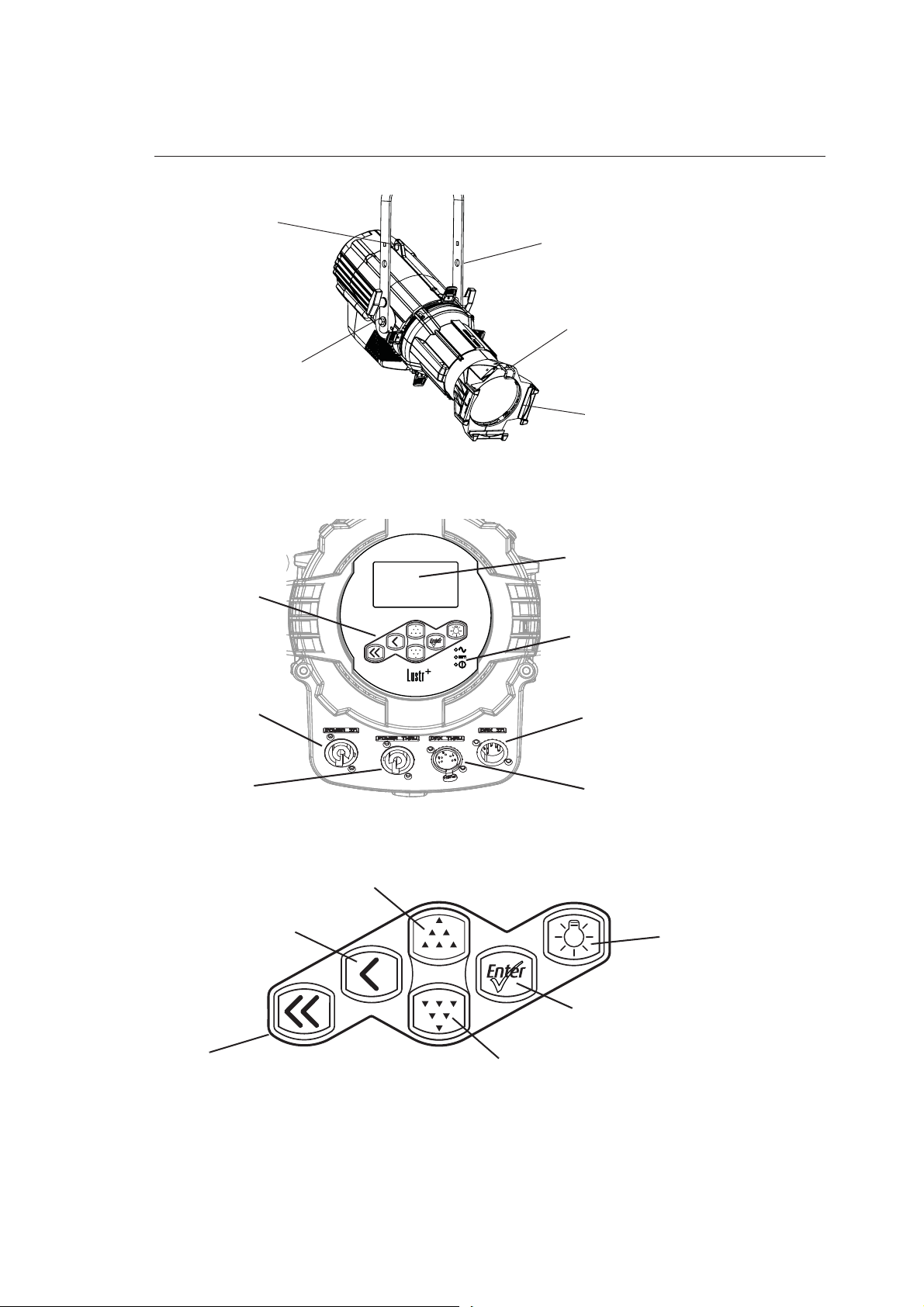
Fixture Components
Color frame
holder
Accessory
retainer
Safety
cable
loop
Yoke
Yoke
locking
knob
Power In
Power Thru
DMX In
DMX Thru
Status
indicators
LCD
Keypad
Figure-1.1 Components of the Source Four LED Profile Fixture.
Figure-1.2 Components of the Rear Panel.
Up
Back
Enter
Home
Figure-1.3 Keypad Button Functions.
For information about the user interface, see User Interface Overview, page 34.
Introduction 3
Down
Light Bulb
Applications
• Theaters • Convention centers
• Studios • Theme parks
• Schools • Museums
• Houses of worship • Temporary events
• Hotels
Document Conventions
Notices
Throughout this manual, the following are used to alert you to notes and safety notices.
Note:
CAUTION:
WARNING:
WARNING:
Please email comments about this manual to: TechComm@etcconnect.com
Notes are helpful hints and information that is supplemental of the main text.
A Caution statement indicates situations where there may be undefined or unwanted
consequences of an action, potential for data loss or an equipment problem.
A Warning statement indicates situations where damage may occur, people
may be harmed, or there are serious or dangerous consequen ces of an ac tion.
RISK OF ELECTRIC SHOCK! This warning statement indicates situations
where there is a risk of electric sh o ck .
Typography Used in This Guide
Menu items and commands you must perform are indicated in bold text. Keypad buttons
are indicated in bold [brackets]. Menu selections or commands appear in bold. For
example:
Press [] to select Sequences and then press [].
4 Source Four LED Profile v1.7.0 User Manual
Safety
The Source Four LED Profile fixtures are intended for professional use only. Read the
entire User Manual before using equipment.
WARNING:
Note the following safety warnings before use:
• Do not mount the Source Four LED Profile fixture on or near a flammable
surface.
• Do not use this fixture with a damaged power lead. If the power lead (co rd
set) is damaged, it must be replaced.
• Do not use this fixture if glass lens is deeply scratched or cracked.
Damaged lenses must be replaced.
• Use theSource Four LED Profile fixture in dry locations only, where
humidity does not exceed 90 percent (non-condensing ). These fixtures are
not intended for outdoor use.
• Mount and support the fixture only by the primary suspension holes in the
yoke or floor standing yoke.
• Suspend the fixture from a suitable structure using only the hardware rated
for the weight of the fixture.
• In addition to primary suspension, attach a safety cable (ETC Model 400SC
or other approved safety cable or device) to the fixture housing.
Appropriate attachment point (hole) is provided in the protruding tab on the
fixture housing.
• Disconnect the unit from power and DMX and allow the fixture to cool
before removing or installing the shutter barrel or other adapters, and all
cleaning and maintenance.
Note:
Introduction 5
• Maximum recommended ambient operating temperature: Ta=40°C (104°F)
• Maximum anticipated external surface temperature: Tmax=80°C (176°F)
• External temperature after 5 minutes of full-brightness operation at 25°C (77°F)
ambient: 29.9°C (85.8°F)
• External Temperature (steady state achieved) at 25°C (77°F): 41.5°C (106.7°F)

Contacts
If you have questions about your Source Four LED Profile fixture that are not answered in
this manual, please contact the supplier of your ETC equipment or ETC Technical Services.
For general information, your most convenient resources are the references provided in this
manual. To search more widely try the ETC web site at www.etcconnect.com.
For technical questions about Source Four LED Profile fixtures, contact ETC Technical
Services directly at one of the offices listed below. Emergency service is available from all
ETC offices outside of normal business hours.
Americas United Kingdom
Electronic Theatre Controls Inc. Electronic Theatre Controls Ltd.
Technical Services Department Technical Services Department
3031 Pleasant View Road 26-28 Victoria Industrial Estate
Middleton, WI 53562 Victoria Road,
800-775-4382 (USA, toll-free) London W3 6UU England
+1-608 831-4116 +44 (0)20 8896 1000
service@etcconnect.com service@etceurope.com
Asia Germany
Electronic Theatre Controls Asia, Ltd. Electronic Theatre Controls GmbH
Technical Services Department Technical Services Department
Room 1801, 18/F Ohmstrasse 3
Tower 1, Phase 1 Enterprise Square 83607 Holzkirchen, Germany
9 Sheung Yuet Road +49 (80 24) 47 00-0
Kowloon Bay, Kowloon, Hong Kong techserv-hoki@etcconnect.com
+852 2799 1220
service@etcasia.com
Please email comments about this manual to: TechComm@etcconnect.com
6 Source Four LED Profile v1.7.0 User Manual

Chapter 1
Installation and User Interface
This chapter contains the following sections:
• Specifications. . . . . . . . . . . . . . . . . . . . . . . . . . . . . . . . . . . . . . .8
• Hardware . . . . . . . . . . . . . . . . . . . . . . . . . . . . . . . . . . . . . . . . .11
• Aim Adjustments . . . . . . . . . . . . . . . . . . . . . . . . . . . . . . . . . . .13
• Installation Clearances . . . . . . . . . . . . . . . . . . . . . . . . . . . . . .18
• Dimensions and Hanging Clearances . . . . . . . . . . . . . . . . . .19
• Power and Data Cabling Requirements. . . . . . . . . . . . . . . . .21
• Connections. . . . . . . . . . . . . . . . . . . . . . . . . . . . . . . . . . . . . . .22
• DMX Profile. . . . . . . . . . . . . . . . . . . . . . . . . . . . . . . . . . . . . . . .23
• Installing Accessories. . . . . . . . . . . . . . . . . . . . . . . . . . . . . . .31
1 Installation and User Interface 7

Specifications
Physical
• Rugged die-cast aluminum construction • Hanging yoke standard
• Easy-access slots for secondary lenses and standard
accessories.
• Advanced thermal management systems for long LED
life
• Ambient operating temperature
0 to 40 °C (32 to 104 °F)
• Continuous operation at 40 °C (104 °F)
Electrical
• 100V to 240V 50/60 Hz universal power input • 5 foot Neutrik PowerCon to bare-end power input lead
• Includes Neutrik
• No more than nine total Source Four LED (four total
Series 2 Lustr) fixtures on Power Thru
®
PowerCon® in and thru connectors
LEDs
• 60 Luxeon Rebel LED emitters (Lustr+ and Series 2
Lustr)
• 33 Osram OSLON Square and 27 Luxeon Rebel LEDs
(Studio HD)
• 50,000 hr. LED life
• 20,000 hr. LED life (Series 2 Lustr)
• Available in black (standard), white (optional), silver, or
custom colors (contact factory)
• Features ultra-quiet cooling fan
•See Fixture Weight, page 20
or parallel blade U-ground (Edison) connector
• Optional 5 foot PowerCon to 20A two pin and ground
(stage pin) or grounded 20A twistlock connector
• Requires power from non-dim source
• 60 Luxeon Rebel ES LED emitters (Daylight and
Tungsten)
•See Note About LED Fixtures, page 10
Optical
• Compatible with all ETC Source Four lens tubes. For
best results, use the preferred lens tubes. See
Preferred Lensing Options, page 12
Control
• DMX512-A compliant • Optional strobe channel
• DMX in and thru via 5-pin XLR connectors • Standalone, studio standalone, and console-free
presets and sequences
• Onboard user interface with a high-resolution LCD • Master/slave mode
• Multiple profile options for different levels of control • 15-bit virtual dimming engine for smooth, high-quality
theatrical fades
• Optional DMX-based fan control for predictable noise
levels
•See DMX Profile, page 23
8 Source Four LED Profile v1.7.0 User Manual
Typical Power Consumption
Lustr+
Idle Power / Current 4.27W / 0.084A 4.38W / 0.079A 4.2W / 0.068A
100% Boost Power / Current 130.8W / 1.48A 129.9W / 1.11A 126.4W / 0.576A
Series 2 Lustr
Idle Power / Current 6.77W / 0.144A 6.9W / 0.149A 6.5W / 0.155A
100% Boost Power / Current 173.0W / 1.94A 171.0W / 1.44A 168.0W / 0.783A
Studio HD
Idle Power / Current 5.69W / 0.096A 5.71W / 0.091A 5.35W / 0.073A
100% Boost Power / Current 129.2W / 1.3A 127.1W / 1.07A 126.2W / 0.564A
Daylight
Idle Power / Current 4.3W / 0.083A 4.35W / 0.077A 4.04W / 0.066A
100% Boost Power / Current 165.2W / 1.87A 163.3W / 1.39A 160.3W / 0.718A
Tungsten
90V 120V 240V
90V 120V 240V
100V 120V 240V
90V 120V 240V
Idle Power / Current 4.3W / 0.085A 4.35W / 0.078A 4.0W / 0.065A
100% Boost Power / Current 159.8W / 1.81A 157.4W / 1.35A 154.8W / 0.695A
Series 2 Daylight HD
Idle Power / Current 5.58W/0.093A 5.69W/0.088A 4.9W/0.06A
100% Boost Power / Current 246.6W/2.481A 245.2W/2.58A 242.3W/1.111A
Series 2 Tungsten HD
Idle Power / Current 5.64W/0.095A 5.71W/0.091A 4.9W/0.061A
100% Boost Power / Current 210.1W/2.1 15A 208.5W/1.752A 205.4W/0.963A
100V 120V 240V
100V 120V 240V
100V 120V 240V
1 Installation and User Interface 9
Note About LED Fixtures
All LED sources experience some lessening of light output and some color shift over time.
Source Four LED Profile fixtures have complex thermal management systems to minimize
these changes. With typical usage, a Series 1 fixture will still achieve at least 70% of its
initial output after 50,000 hours of use (B50, L70). A Series 2 fixture will achieve 70% of its
initial output after 25,000 hours of use (B50, L70). In individual situations, LEDs will be used
for different durations and different levels. This can eventually lead to minor alterations in
color performance, necessitating slight adjustment to presets, cues, or programs.
All LEDs may exhibit a slight shift in output as they rise to full operating temperature. Source
Four LED Profile fixtures allow the selection of different power settings in order to balance
the competing requirements of thermal stability and brightness. Depending on the selected
setting, changes in output as fixtures warm up may or may not be visible to the eye.
Color Rendering Index and Color Quality Scale Ratings
Source Four LED Profile fixtures are evaluated for Color Rendering Index (CRI) and Color
Quality Scale (CQS) performance using measured output spectrum and optimized mix
solutions for a best spectral match to black body sources at 3200K and 5600K. Color fidelity
was also measured. These numbers may fluctuate slightly from fixture to fixture. This is a
normal characteristic of white LEDs, and this kind of variation is highly unlikely to be
apparent in most applications. The performance is the same for all fixture versions.
Fixture CRI CQS Color Fidelity Duv
Lustr+ Reg at 3200K 84 87 87 0.000
Lustr+ Reg at 5600K 92 92 92 0.000
Series 2 Lustr at 3200K 86 88 88 0.000
Series 2 Lustr at 5600K 90 91 91 0.000
Studio HD at 3200K 94 95 93 0.000
Studio HD at 5600K 91 87 86 0.000
Tungsten at 3000K 86 86 86 0.001
Daylight at 5600K 71 70 69 0.001
Series 2 Daylight HD at 3200K 89 89 88 0.004
Series 2 Daylight HD at 5600K 91 89 88 0.002
Series 2 Tungsten HD at 3200K 94 91 91 0.002
Series 2 Tungsten HD at 5600K 85 86 84 0.004
Source Four LED Profile luminaires provide excellent color rendering, particularly the colormixing versions. A Duv rating of 0.000 indicates that the color mix used was exactly on the
black body line, with no green or magenta tint.
Daylight and Tungsten fixtures use only white-type LEDs at a fixed color temperature in
order to maximize output and efficacy.
10 Source Four LED Profile v1.7.0 User Manual
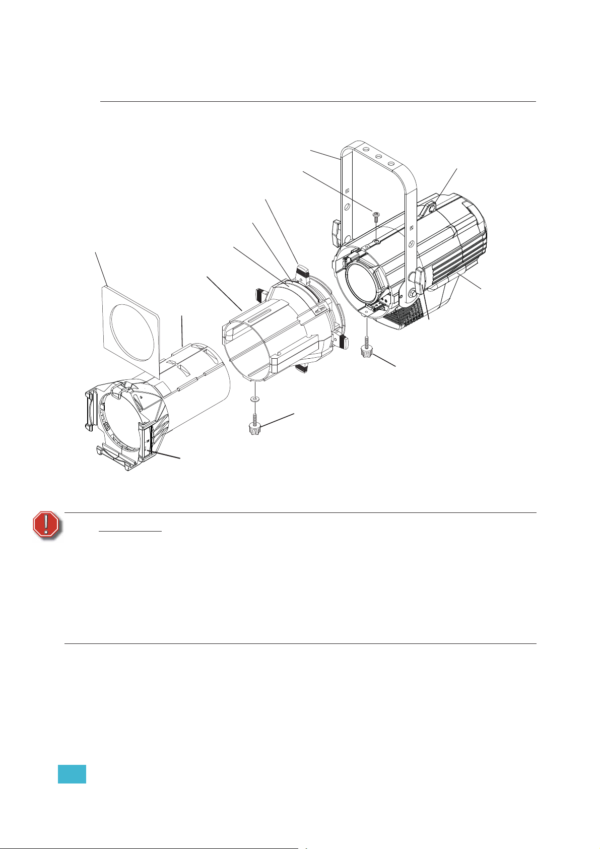
Hardware
Basic Assembly
Color frame
Pattern holder slot
Drop-in iris slot
Shutter barrel
assembly
Lens tube
Retainer bolt
Shutters
Yoke
Beam focus knob
Safety
cable
loop
Light engine
body
Yoke locking knob
Barrel rotation knob
Color frame holder
Figure-1.1 Basic assembly.
WARNING:
Please note the following safety warnings before use:
Do not mount the fixture on or near combustible surfaces.
Do not operate the fixture without a lens installed.
Always hang the fixture with the color frame retaining clip in the locked
position.
Always use a properly installed safety cable.
Disconnect the unit from power and DMX and allow the fixture to cool before
removing or installing the shutter barrel or other adapters, a nd a ll cleaning
and maintenance.
Mounting Hardware
A yoke is provided for mounting fixtures. For more information See “Adjusting the Yoke
Position” on page 17.
NOTE: Safety cable is not included.
1 Installation and User Interface 11
Install Lens Tube
Any of the ETC Source Four lens tubes can be installed into the shutter barrel of the Source
Four LED Profile. For better results, use one of the preferred lens tubes listed below.
Figure-1.2 Secure lens tube with zoom knob and Phillips screw.
Step 1: Slide the lens tube into shutter barrel.
Step 2: Install the lens zoom knob.
Step 3: Install the Phillips screw in the top of the lens barrel.
Preferred Lensing Options
Phillips screw
Beam focus knob
Fixed Beam Lenses
Model Description
LED50LT LED specific 50° EDLT with lenses installed
LED50LT-1 LED specific 50° EDLT (white) with lenses installed
436EDLT 36° EDLT w/lens installed
436EDLT-1 36° EDLT (white) w/lens installed
426EDLT 26° EDLT w/lens installed
426EDLT-1 26° EDLT (white) w/lens installed
419EDLT 19° EDLT w/lens installed
419EDLT-1 19° EDLT (white) w/lens installed
490LT 90° w/lens installed
490LT-1 90° (white) w/lens installed
470LT 70° w/lens installed
470LT-1 70° (white) w/lens installed
414LT 14° w/lens installed
414LT-1 14° (white) w/lens installed
410LT 10° w/lens installed
410LT-1 10° (white) w/lens installed
405LT 5° w/lens installed
405LT-1 5° (white) w/lens installed
Zoom Lens Assemblies
Use with light engine body without the shutter barrel.
Model Description
41530LT Source Four 15-30 Zoom lens assembly
42550LT Source Four 25-50 Zoom lens assembly
12 Source Four LED Profile v1.7.0 User Manual
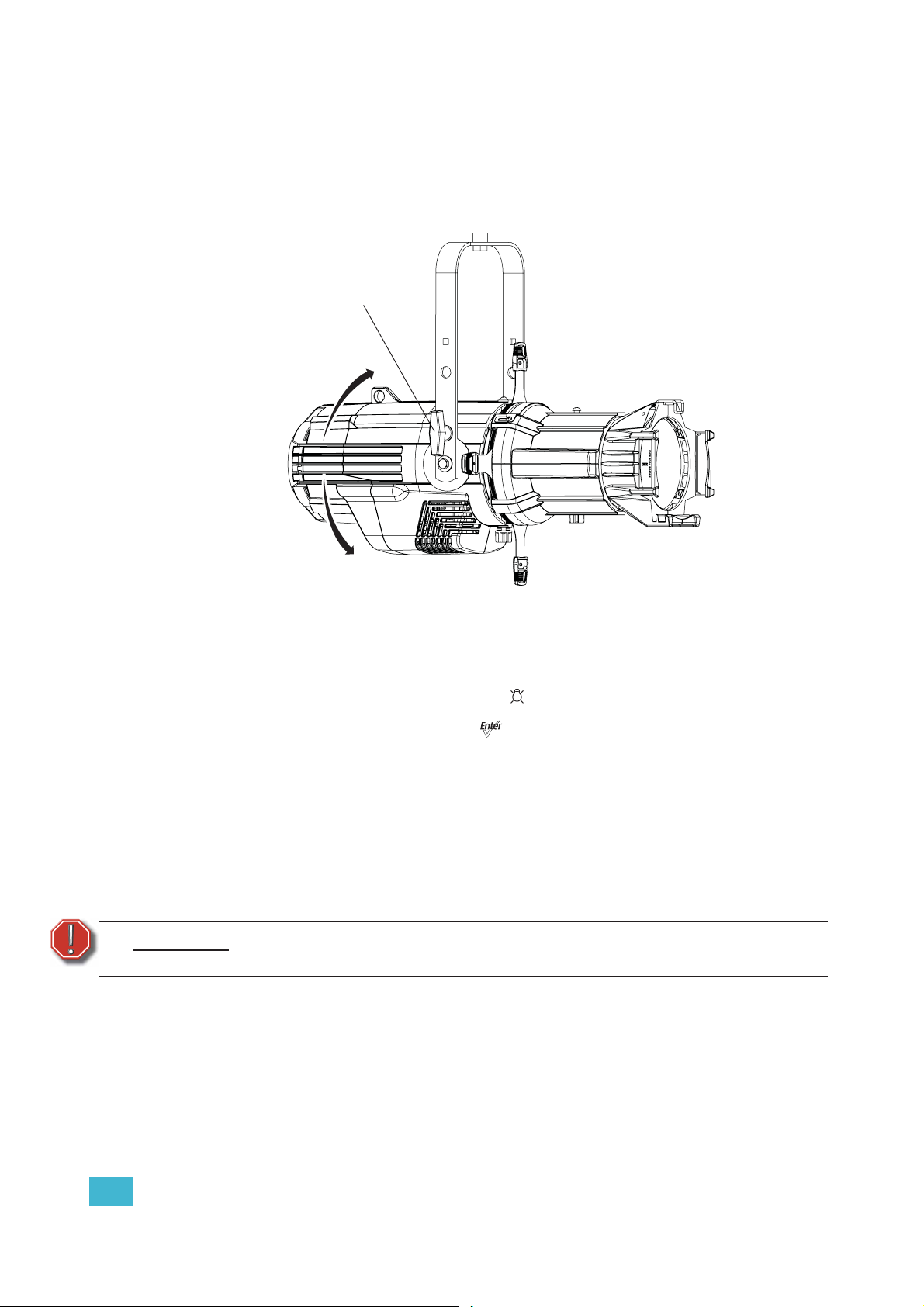
Aim Adjustments
The fixture can be tilted up and down to aim the light where it is needed. The adjustment is
the same for the yoke or floor stand. To assist aiming the fixture, you can turn it on without
having to be connected to DMX control or enabling a preset. For more information, see
Focus, page 52.
Yoke locking
knob
Figure-1.3 Tilting the Fixture on the Yoke.
Turning the Fixture On
Step 1: Apply power to the fixture.
Step 2: On the back of the fixture press [].
Step 3: With Focus selected, press [].
Adjusting the Tilt
Step 1: Loosen the yoke locking knobs. Do not remove them.
Step 2: Tilt the fixture to the desired position.
Step 3: Tighten the yoke locking knobs to secure in position.
Adjusting the Pan
The pan is adjusted at the hanging clamp. Please consult the clamp manufacturer’s
documentation for instructions on loosening and rotating the yoke at the clamp.
WARNING:
A safety cable (or other approved safety device) must be securely attac hed to
the safety cable loop before loosening the clamp.
1 Installation and User Interface 13
Focusing the Beam
Beam focus knob
Figure-1.4 Focusing the beam.
Step 1: Loosen the beam focus knob located under the barrel as shown in Figure-1.4.
Step 2: Slide the lens tube forward or backward to achieve the desired beam edge.
Step 3: Once the fixture is focused, tighten the beam focus knob.
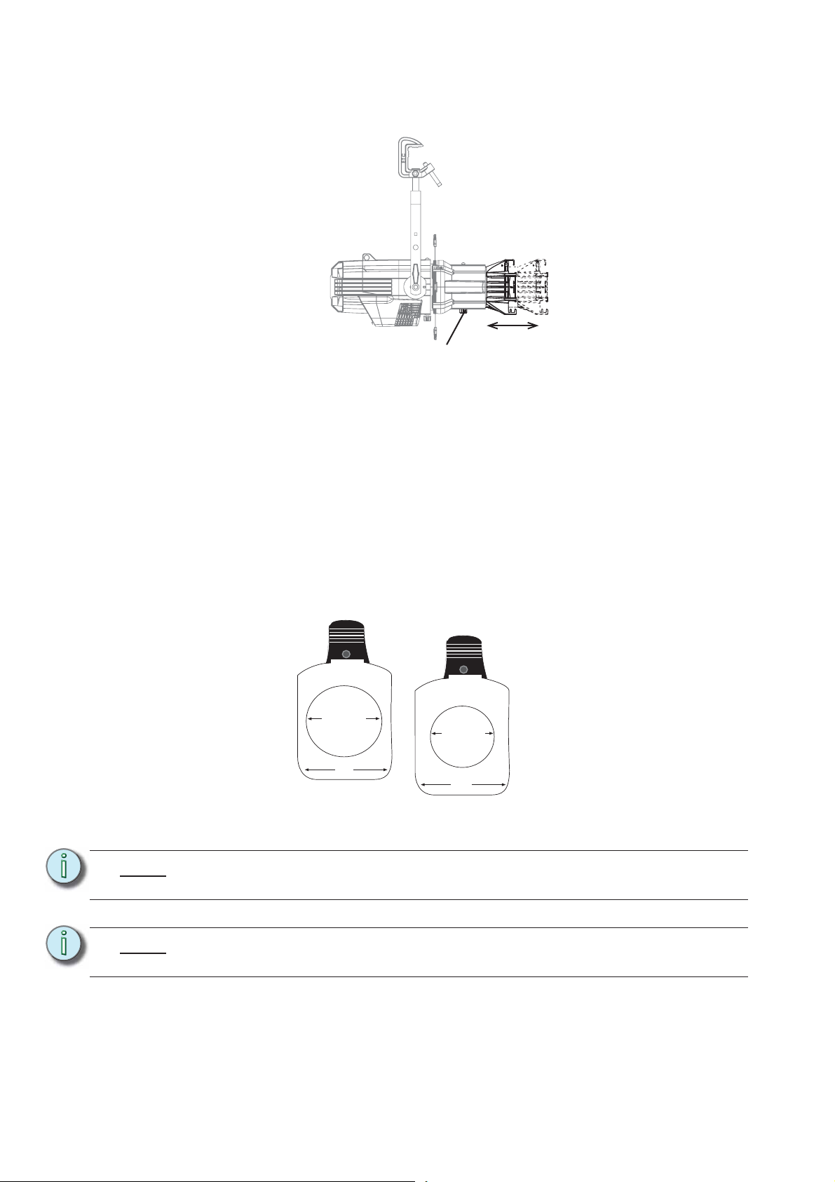
Shaping the Beam
The beam can be shaped using the shutters (see Figure-1.1), a pattern, an optional drop-in iris, or
by rotating the barrel.
Pattern Projection
The pattern holder slot is on the top side of the barrel and in front of the shutters. It accommodates
A-size, B-size, and glass pattern holders.
A-Size Pattern holder: holds 3”
diameter patterns
B-Size Pattern holder:
holds 2.5” and 2.75”
diameter patterns
3.12" Diameter
2.75" Diameter
3.70"
3.70"
Figure-1.5 Pattern holders.
Note:
Pattern projections generally look best when used with the included Soft Focus
diffuser.
Note:
Because the Source Four aperture is 3 inches wide, ETC recommends using A-size
patterns for maximum pattern effectiveness.
14 Source Four LED Profile v1.7.0 User Manual
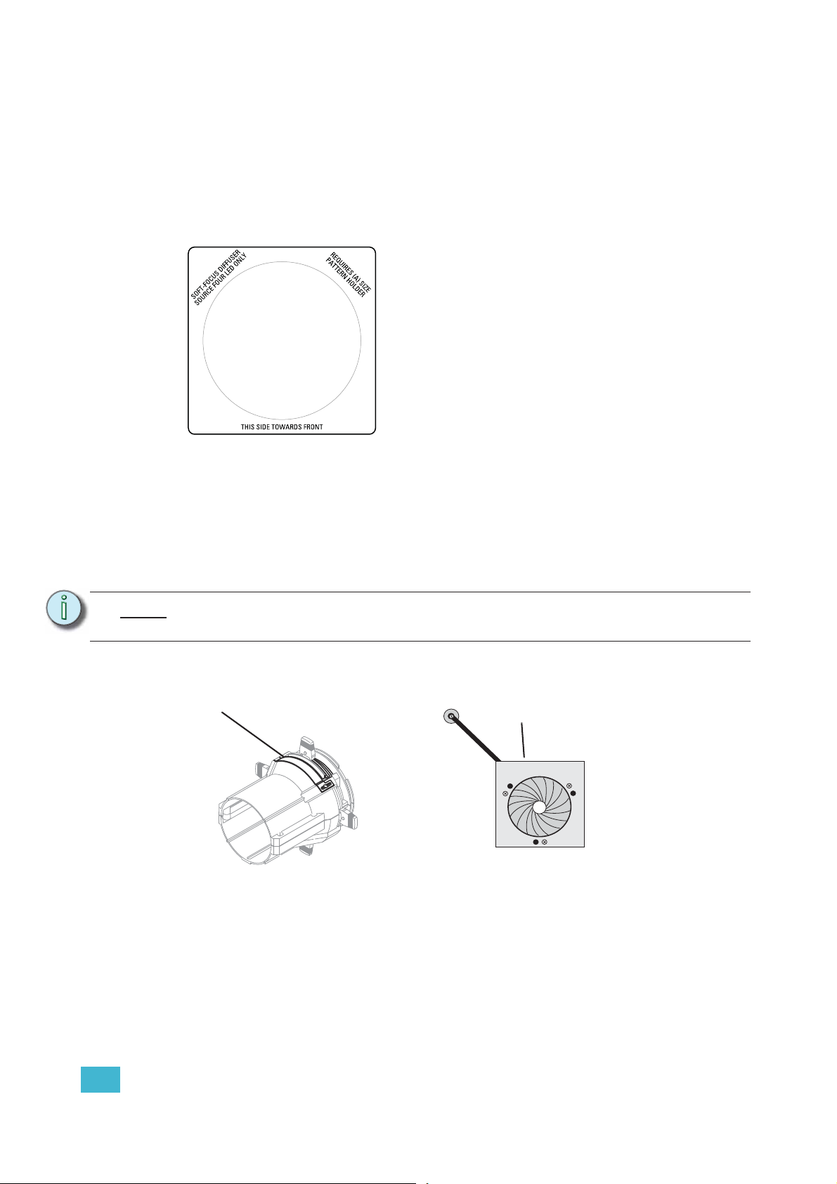
Soft Focus Diffuser
To clean up edge effects, use the soft focus diffuser in the A-size pattern holder. If
combining the diffuser with a pattern, put the diffuser behind the pattern. The soft focus
diffuser allows you to maintain sharp focus of the pattern while eliminating edge effects. The
diffuser is intended for Source Four LED fixtures only.
A permanent install kit is available.
Figure-1.6 Soft Focus diffuser.
Step 1: Install the diffuser into an A-Sized Pattern holder.
Step 2: Install a pattern in front of the diffuser, if needed.
Step 3: Insert the pattern holder and diffuser into the Pattern holder slot, making sure the
writing on the diffuser faces the front of the fixture.
Also see Smooth Wash Diffuser, page 31.
Note:
Enhanced Definition Lens Tubes (EDLT) are highly recommend for use with Source
Four LED Profile luminaires to provide a crisper pattern projection.
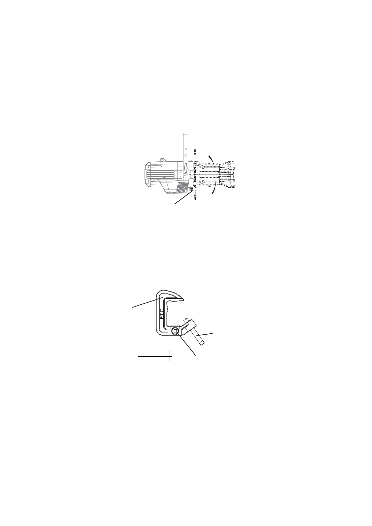
Accessory Slot
Accessory slot
Figure-1.7 Accessory slot
The accessory slot is located on the top of the shutter barrel and in front of the pattern holder slot.
It accommodates either a drop-in iris or a motorized pattern device. When the slot is not in use, a
small sheet metal cover secured with two Phillips screws prevents light leakage.
Iris
1 Installation and User Interface 15
Step 1: Use a Phillips screwdriver to loosen the screws on the drop-in iris slot cover. Do
not remove screws.
Step 2: Slide the cover completely forward to expose the slot.
Step 3: Insert the iris or motorized pattern device. For an iris, install the flat side toward
the shutters and make sure the iris handle extends from the slot.
Step 4: Slide the slot cover back toward the shutters until it meets the iris handle. Leave
enough space to move the iris handle.
Step 5: Secure the accessory slot cover by tightening the screws.
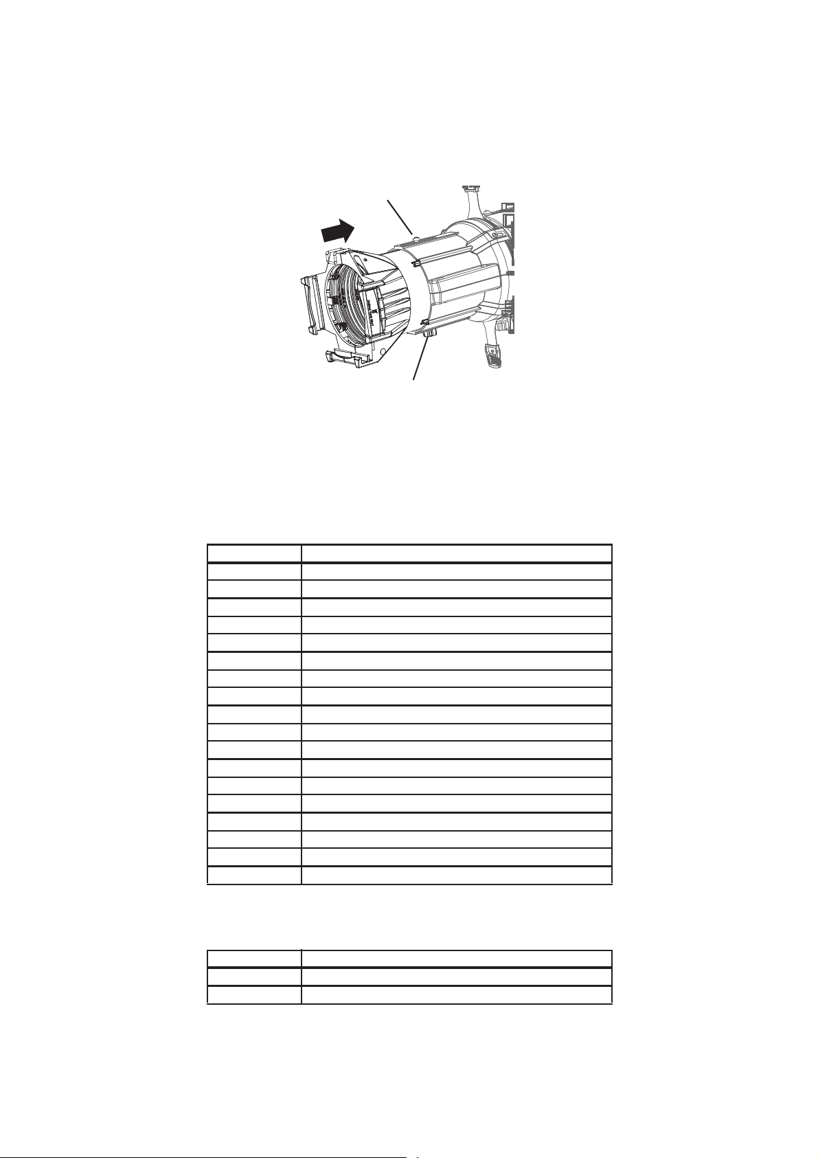
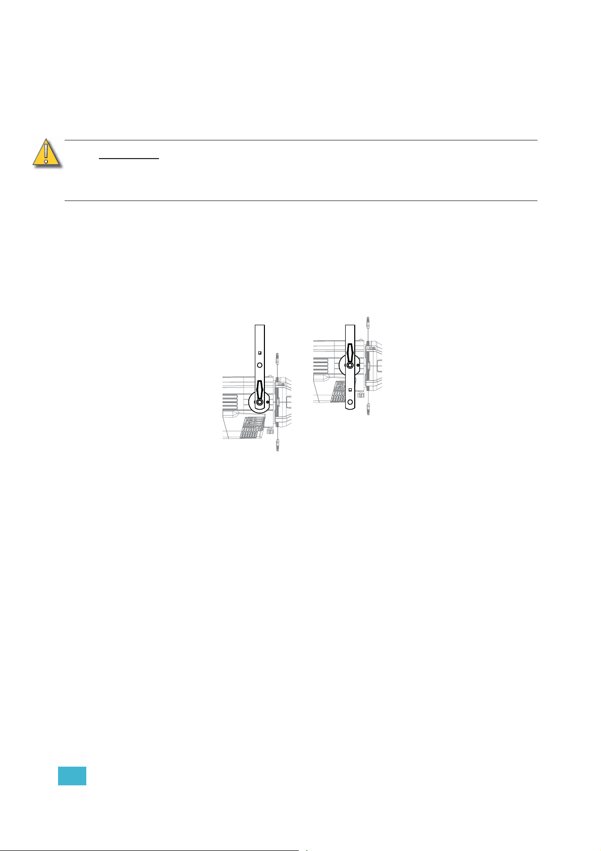
Rotating the Shutter Barrel Assembly
Barrel rotation knob
Figure-1.8 Rotating the shutter barrel assembly
Step 1: Loosen the shutter barrel rotation knob directly behind the shutters on the
underside of the reflector housing. Do not remove the barrel rotation knob.
Step 2: Rotate the shutter barrel to the desired position (up to 25° in either direction from
the centered position).
Step 3: Once the shutter barrel is positioned, tighten it’s rotation knob to lock it in place.
Adjusting the C-clamp For North America
C-clamp
Pipe bolt
Yoke bolt and lock
washer
Figure-1.9 Adjusting the C-clamp.
The C-clamp attaches the fixture to the mounting pipe and allows fixture adjustments when
mounted.
Pan screw
16 Source Four LED Profile v1.7.0 User Manual
Step 1: Secure the C-clamp to the yoke with the provided yoke bolt and lock washer.
Step 2: Place the C-clamp on the mounting pipe and secure by tightening the pipe bolt.
Step 3: Loosen the C-clamp pan screw and rotate the yoke to the desired position.
Step 4: Retighten the pan screw to lock the fixture.
CAUTION:
Tighten C-clamp pipe bolt to 15-20 ft./lbs. (approximately finger tight plus up to
one-quarter turn). Do not exceed 25 ft./lbs. Do not use excessive force.
Tighten the yoke pivot bolt to 5-10 ft./lbs. (approximately finger tight plus up to
one-eighth turn). Do not exceed 15 ft./lbs. Do not use excessive force.
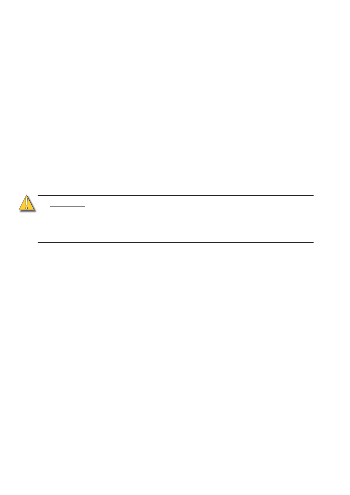
Adjusting the Yoke Position
The Source Four provides multi-positioning capabilities within its yoke for overall fixture height and
angle.
Setting the Fixture Height Within the Yoke
The Source Four has a two-position yoke for modifying the overall mounting height.
.
General use position
Low clearance position
Figure-1.10 Adjusting the yoke position.
To change the fixture yoke position:
Step 1: Remove the yoke locking knobs, washers, and hex bolts from either side of the
fixture.
Step 2: Raise or lower the fixture to the desired position within the yoke.
Step 3: Reinstall the yoke’s hex bolts, washers, and locking knobs.
Step 4: Tighten the yoke knobs to secure in position.
1 Installation and User Interface 17
Installation Clearances
Cooling and Duty Cycle
Source 4 LED fixtures are fan cooled and can operate all channels at full power
continuously in ambient temperatures up to 40°C (104°F).
If ambient conditions exceed 40°C (104°F) or fail to allow sufficient airflow, over a long
period of time, the fixtures may shut down and remain off until they return to a safe
operating temperature. The fixtures provide two methods to indicate over temperature that
can be set up on the Local Settings menu. The over temperature indicators are:
Visible
The LED array glows in a dull, low intensity with only some emitters illuminated, the LCD
backlight is turned on, the LCD displays Overtemp Activated, and the Error Indicator light
turns on.
Dark
The LED array turns off and the LCD displays Overtemp Activated. The LCD backlight is
not turned on.
CAUTION:
LED life is adversely affected by high-temperature operation. When operating under
elevated ambient temperatures, avoid turning all channels to 100% for extended periods,
such as channel checks or focusing.
Duty Cycle
Operating the fixtures in higher ambient temperatures or low-airflow situations may
cause the power supply to shut down. Following a cool-down period, the power
supply will automatically reset and the fixture will return to operation.
It is good practice to power down any device with on-board electronics to limit
unnecessary wear on the devices and eliminate residual use of electricity.
18 Source Four LED Profile v1.7.0 User Manual
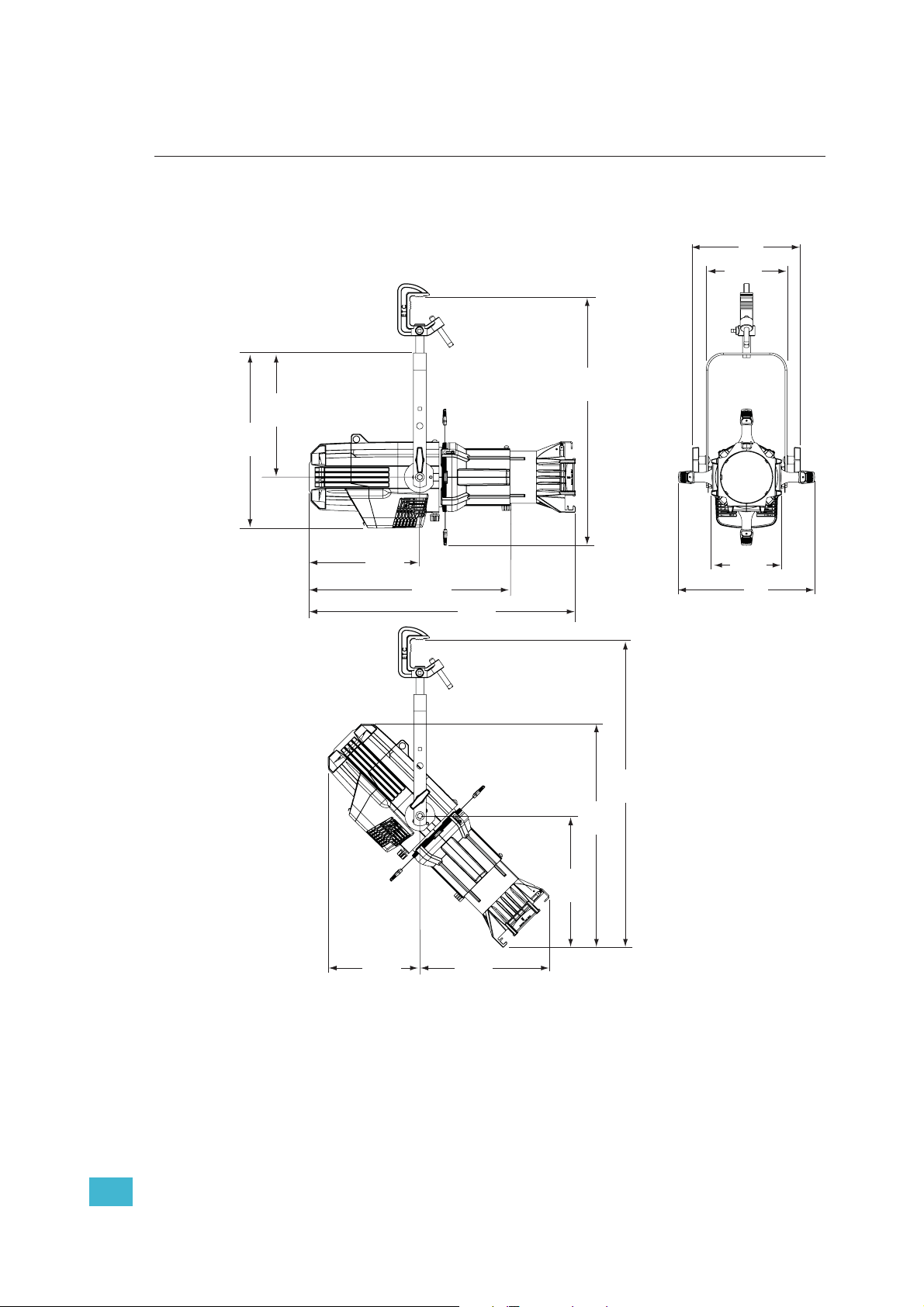
Dimensions and Hanging Clearances
Use the following dimensions to allow proper clearances around the fixture. Allow additional
space for cables.
24.2”
615mm
17.1”
434mm
12.1”
308mm
10.6”
268mm
7.9”
200mm
10.8”
274mm
9.2”
233mm
19.56”
497mm
25.9”
659mm
12.9”
328mm
13.1”
333mm
22.3”
566mm
30.7”
779mm
6.9”
174mm
13.3”
338mm
Figure-1.11 Dimensions with typical 19°, 26° or 36° lens tube fully extended. Other lens tubes
available, but not shown.
1 Installation and User Interface 19
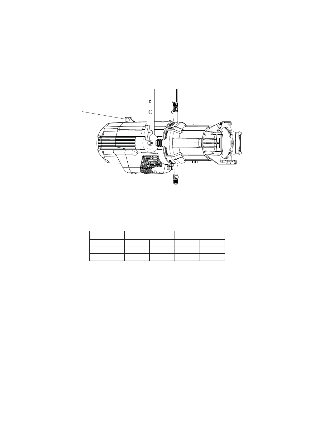
Safety Cable
A safety cable (or other approved safety device) should be attached to the fixture housing
and wrapped around the hanging structure (pipe). An appropriate attachment loop is
provided on the protruding tab of the fixture housing. Take care to leave as little slack as
possible in the safety cable to avoid the cable catching the yoke of the fixture.
Safety cable
loop
Figure-1.12 Safety Cable Loop on Fixture Housing.
Fixture Weight
Total weight depends on how the individual fixture is configured.
With barrel
Without barrel
Model
Lbs.Kg.Lbs.Kg.
19.0 8.6 28.7 13.0
15.0 6.8 23.7 10.8
a) Does not include mounting hardware.
Weight
a
Shipping Weight
20 Source Four LED Profile v1.7.0 User Manual
Power and Data Cabling Requirements
Power
The Source 4 LED fixture operates on AC power, 100 to 240VAC/50-60Hz. The fixture must
be connected to a non-dimmable power source in order to avoid damage to its internal
power supply and other electrical components.
WARNING:
Data
The Source 4 LED fixtures operate on a DMX control signal or as standalone fixtures. The
fixture is supplied with a 5-pin XLR DMX input connector and a 5-pin DMX Thru connector.
DMX cables should be acceptable for DMX data transmission (not microphone cable) and
should follow the standard pinout. The optional secondary data pair is not used by the
Source 4 LED fixtures. The maximum DMX data run from any DMX source to the last fixture
in a chain is 1000 feet (300m). Source 4 LED fixtures are self-terminated.
See DMX Profile, page 23 for additional information on DMX addressing of Source Four
LED Profile fixtures.
The fixture must be connected to a non-dimmable power source in order to
avoid damage to its internal power supply and other electrical components.
Dimming will damage the fixture and void the warranty.
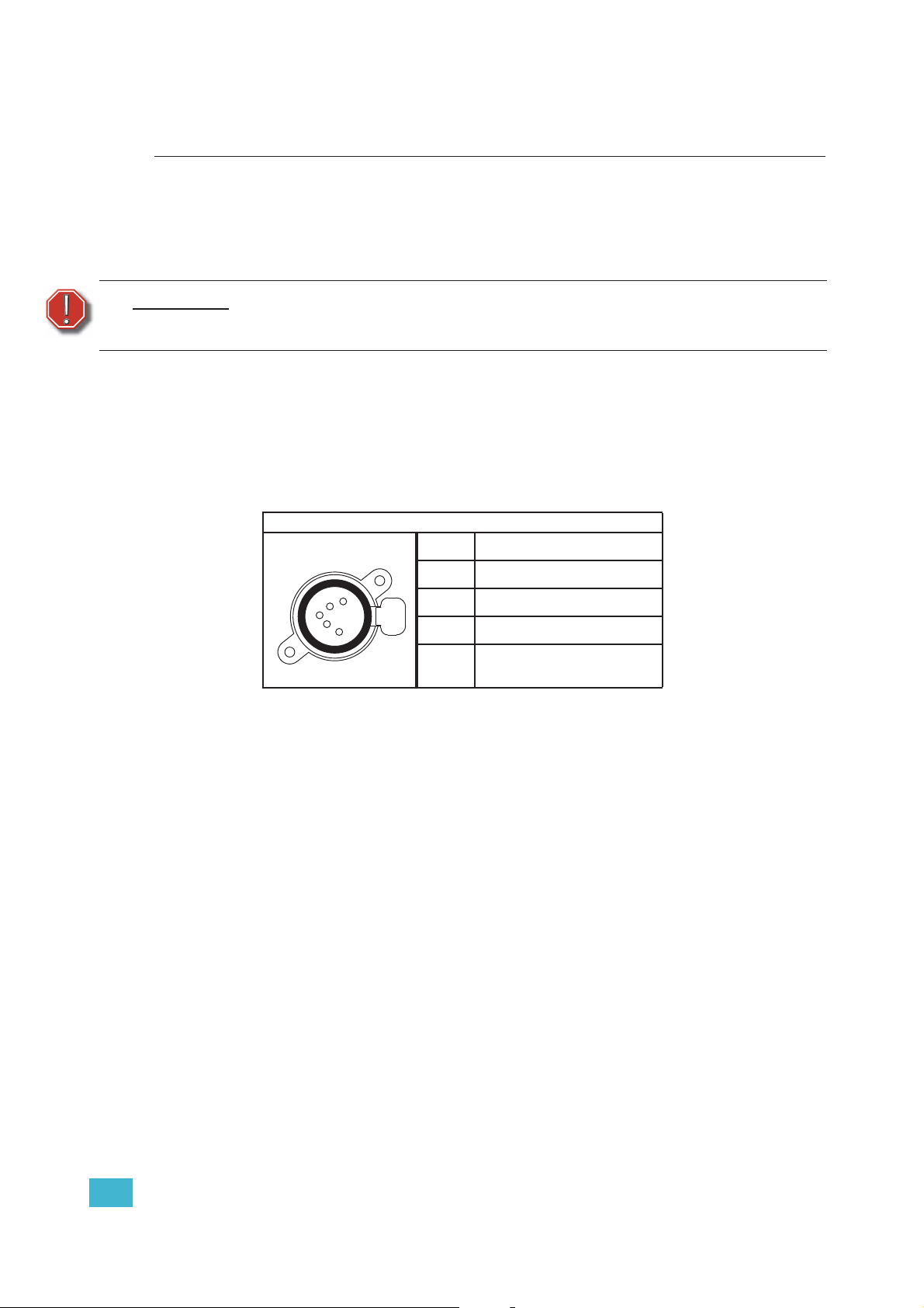
DMX512 pinout for five-pin XLR female
1 Common (Shield)
5
4
3
2
1
2Data –
Push
3Data +
4 not connected
5 not connected
1 Installation and User Interface 21
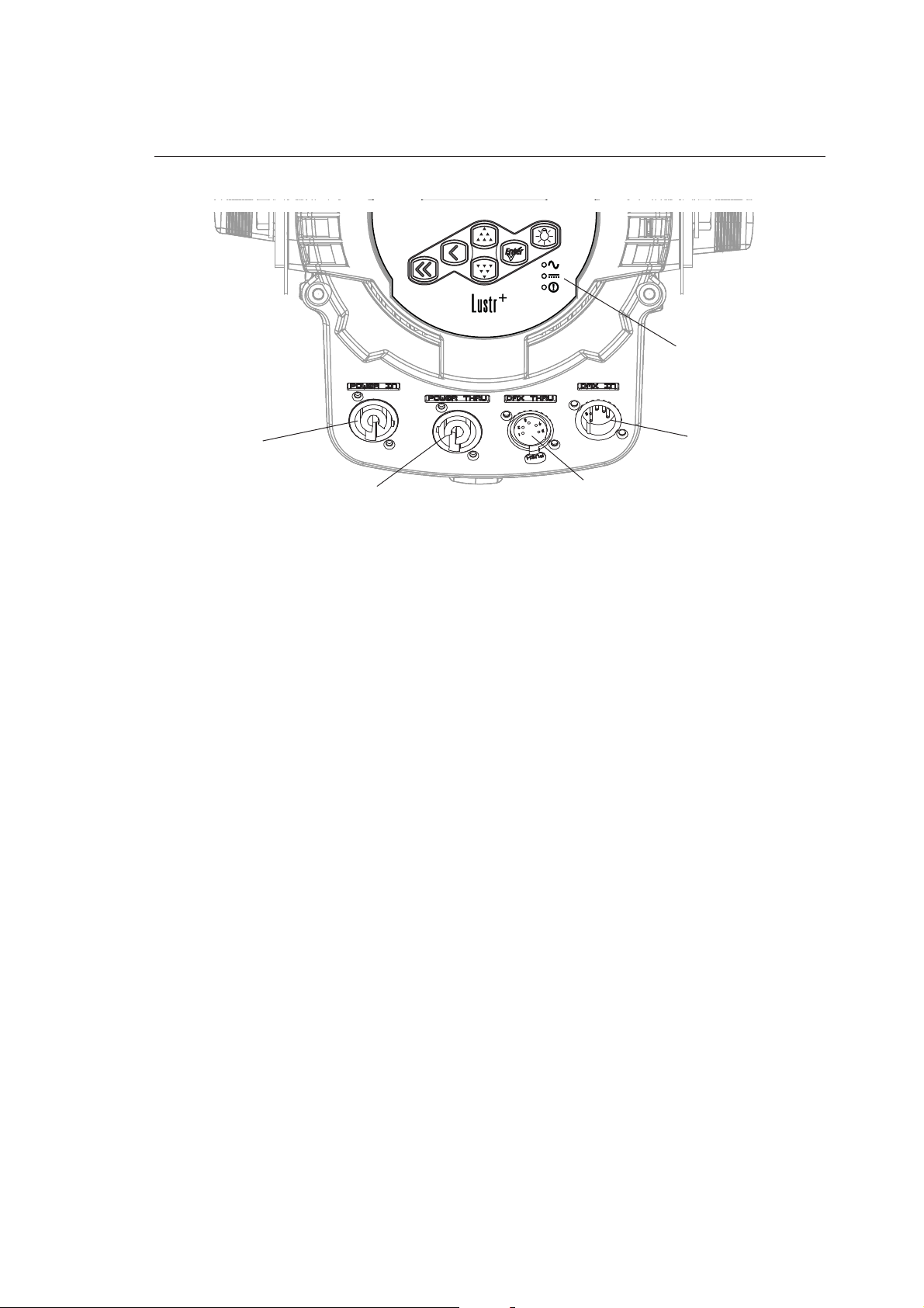
Connections
All connections and user controls are located on the back of the fixture.
Status indicators
Power In
Power Thru
Figure-1.13 Power and DMX Connections on Back of Fixture.
Connect AC input power and DMX data cables to the appropriate ports. Connect the
incoming DMX data cable to the DMX Input connector. If you are daisy-chaining the data
to other fixtures or DMX-controlled devices, connect the next DMX cable to the DMX Thru
connector. Up to 32 fixtures can be connected together into a data daisy-chain.
For information about the user interface, refer to User Interface Overview, page 34.
Source Four LED Series Connections
AC cable
Connect:
Align and insert the power connector. Twist the connector clockwise until it locks into place.
Disconnect:
Slide back the locking tab to unlock, twist the connector counterclockwise, and then pull and
disconnect the power connector.
DMX cable
DMX In
DMX Thru
Connect:
Align and insert the DMX connector.
Disconnect:
Press the release button on the connector or on the fixture and pull the connector out.
Indicator Lights
The indicator lights show the status of power input (blue), DMX input (green) and fixture
errors (red). When the DMX signal is lost, the green indicator flashes.
If the fixture status indicator is configured to Off, the indicator lights will not illuminate. For
more information, see Local Settings, page 68.
22 Source Four LED Profile v1.7.0 User Manual
DMX Profile
Addressing
Addresses must be set between 1 and 510.
Each Source Four LED Profile fixture must be considered a separate DMX device for
the purpose of DMX line-loading calculations.
DMX line-loading practice dictates that no more than 32 devices can be daisy-chained
together. Consequently, no combination of Source Four LED Profile fixtures totaling more
than 32 DMX devices should be configured in one DMX line. For runs of fixtures totaling
more than 32 DMX devices, split the DMX runs by using a DMX splitter.
Note:
Depending on the selected fixture profile and activated features, a fixture with a
starting address higher than 499 may not have control of all parameters, even though
the highest address shown on the user interface is 512.
Addressing is not required for standalone operation.
Profiles
Source Four LED and Source Four LED Series 2 fixtures occupy 1 to 15 DMX channels
depending on the profile and which features are turned on. The tables below describe the
order and function of each channel.
Lustr+, Series 2 Lustr, Series 2 Daylight HD, Series 2 Tungsten HD, and Studio HD
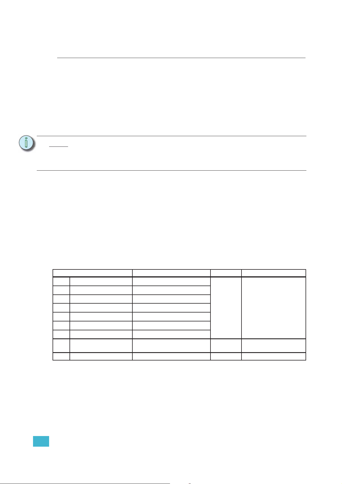
Direct Control
Direct Control uses one DMX channel per individual color within the LED array for a total of
seven color channels, arranged according to the Color Mixes table. Each controls the
intensity of the color from 0 to 100%. An additional, 8th DMX channel is used as a master
intensity fader for controlling the brightness of the overall fixture. Channel 9 is for strobe
when enabled.
Data Channel Control Value Function
1 Fixture address
2 Fixture address + 1
3 Fixture address + 2
4 Fixture address + 3
5 Fixture address + 4
6 Fixture address + 5
7 Fixture address + 6
8 Fixture address + 7 Intensity
9 Fixture address + 8 Strobe Variable strobe control
a) See Color Mixes, page 24.
Color 1
Color 2
Color 3
Color 4
Color 5
Color 6
Color 7
a
a
a
a
a
a
a
0 to 255
Color intensity 0 to100%
Overall intensity 0 to
100%
1 Installation and User Interface 23
Color Mixes
The following table shows the color mixes for the fixture.
Color Lustr+ Series 2 Lustr Studio HD
1Red Red Red
2 White Lime Red Orange
3Amber Amber Mint
4 Green Green Blue
5CyanCyanIndigo
6 Blue Blue —
7 Indigo Indigo —
Terminology:
• White Point - The color temperature of a white light when saturation is at zero%.
• Tint - The balance between green and magenta within a fixture.
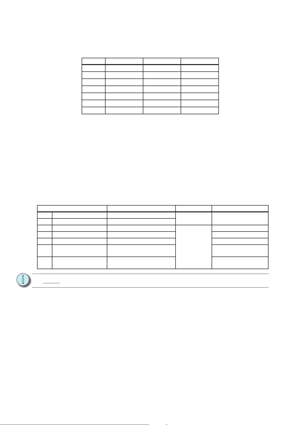
HSI and HSIC:
The HSI profile (Hue, Saturation, Intensity) uses four channels of DMX input, corresponding
to 16-bit hue (two channels: coarse and fine), saturation, and intensity. The HSI profile
makes Source Four LED Profile fixtures compatible with conventional HSI console profiles
while capitalizing on fixtures' expanded color capabilities. Channel 5 is for Strobe, when
enabled. Also see Color Matching, page 26.
The HSIC profile (Hue, Saturation, Intensity, Color Temperature (White Point)) is similar to
HSI, except that it uses an additional sixth channel to control the color temperature of the
white point. The Red Shift function is automatically disabled in the HSIC profile.
Data Channel Control Value Function
1 Fixture address Hue coarse
2 Fixture address + 1 Hue fine
3 Fixture address + 2 Saturation
4 Fixture address + 3 Intensity Intensity 0 to 100%
5 Fixture address + 4 Strobe Variable strobe control
6 Fixture address + 5 Fan control
7 Fixture address + 6 White point
Note:
The HSI profile is optimized for maximum brightness at all settings.
0 to 65535
0 to 255
Hue 0
Saturation 0 to 100%
Force fan on various
speeds
Color temperature 2700 to
6500K
RGB
Effectively addresses all seven colors via three channels of control. The RGB profile
produces medium-quality color crossfades. It makes the Source Four LED Profile fixtures
compatible with conventional RGB console profiles while maintaining enhanced color
24 Source Four LED Profile v1.7.0 User Manual
 Loading...