

Page 1

CE Sensor Rack (ESR Series)
®
ECEM to CEM3 Retrofit Manual
Revision A
Copyright © 2011 Electronic Theatre Controls, Inc.
All Rights reserved.
Product information and specifications subject to change.
Part Number:
Released: September 2011
7144M2310
Rev A
Page 2

ETC permits the reproduction of materials in this manual only for non-commercial purposes. All
other rights are reserved by ETC.
®
ETC
, and Sensor® are registered trademarks of Electronic Theatre Controls, Inc. in the United
States and other countries.
All other trademarks, both marked and not marked, are the property of their respective owners.
ETC intends this document, whether printed or electronic, to be provided in its entirety.
Page 3
Introduction
This manual is intended to guide ETC Service Technicians through the process of
upgrading existing CE Sensor rack installations to Sensor3 racks with a CEM3 control
module. This manual covers ESR12, ESR24, ESR36 and ESR48 permanent installation
dimming racks.
Contacting ETC Technical Services
If you have questions about the retrofit process that are not answered in this manual, please
contact ETC Technical Services.
United Kingdom Germany Asia
Electronic Theatre Controls Ltd. Electronic Theatre Controls, GmbH Electronic Theatre Controls Asia, Ltd.
Technical Services Department Technical Services Department Technical Services Department
26-28 Victoria Industrial Estate Ohmstrasse 3 Room 1801, 18/F
Victoria Road, 83607 Holzkirchen, Germany Tower 1, Phase 1 Enterprise Square
London W3 6UU England +49 (80 24) 47 00-0 9 Sheung Yuet Road
+44 (0)20 8896 1000 techserv-hoki@etcconnect.com
service@etceurope.com
Kowloon Bay, Kowloon, Hong Kong
+852 2799 1220
service@etcasia.com
Please email comments about this manual to: TechComm@etcconnect.com
Warnings and Notice Conventions
These symbols are used in Sensor documentation to alert you to danger or important
information:
Note:
CAUTION:
WARNING:
WARNING:
Notes are helpful hints and information that is supplemental to the main text.
A Caution statement indicates situations where there may be undefined or
unwanted consequences of an action, potential for data loss or an equipment
problem.
A Warning statement indicates situations where damage may occur, people
may be harmed, or there are serious or dangerous consequences of an
action.
RISK OF ELECTRIC SHOCK! This warning statement indicates situations
where there is a risk of electric shock.
Introduction 1
Page 4

Safety
Please note the following safety warnings before use:
• Disconnect power from the racks before all maintenance.
WARNING:
Dimmer racks without an accessible power disconnect device cannot be
serviced safely. Before removing dimmer or control modules for service, deenergise main feed to dimmer rack and follow the appropriate safety
procedures for your region.
Overview of this Manual
Reference this manual throughout the retrofit procedure. The major sections of the
procedure are:
• Preparation, page 5 - before you open the rack.
• Remove the Old, page 5 - labeling and remove the existing equipment.
• Data Terminations, page 7 - adapting and connecting the data terminations.
• Attach new power harness, page 8 - adapting and connecting the power harness for
the new backplane.
• Install the New Backplane, page 10 - transfer the wiring and install new components.
• Change out the AF Cards (if present), page 11 - remove the existing Advanced Feature
cards and install the new ones.
• Change out the Beacon PCB, page 12 - replace the beacon pcb with the new one.
• Verify the Retrofit, page 13 - put the dimmers back in the rack and power up the rack.
• Configure the CEM3, page 13 - program a configuration for the CEM3.
When viewing this document in electronic form (.pdf file) with Adobe Acrobat Reader, blue
italicised text followed by a page number such as “Overview of this Manual, page 2” is a
link within the document. If you click on the link, it will jump to that section or topic.
2 CEM3 Sensor ESR Rack Retrofit Manual
Page 5
Section 1
Unpack and Organise
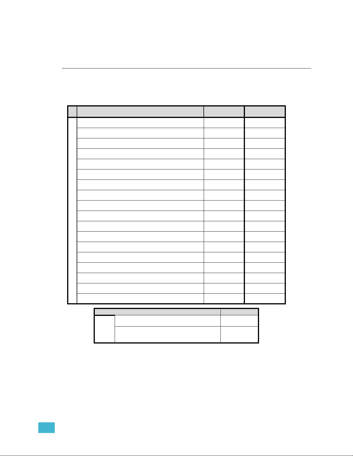
The table below lists the parts and components needed to retrofit a CE Sensor rack
(ESR12, 24, 36 or 48) to become a Sensor3 rack with a CEM3. Each part is listed to reflect
the different quantities for the different kits and types of racks.
Parts/Components
ETC Part Number
Beacon Door Acrylic
7051A4116
CAT5 Termination Kit
4101A2003
Sensor3 Beacon Blue Assembly
7141B5109
Sensor3 Install Rack Door Label
7141A4001
8-pin Screw Terminal Data Connector
J3407-F
ECEM Classic to CEM3 Power Adapter Harness, ESR12
7144B7002
ECEM Classic to CEM3 Power Adapter Harness, ESR24-48
7144B7003
CE Sensor3 Install Rack Backplane Assembly, Sgl Height
7144A2000-CFG
CE Sensor3 Install Rack Backplane Assembly, Dbl Height
7144A2001-CFG
Sensor+/3 Filler Module
7150A3010
Sensor Rack CEM Classic to CEM3 Retrofit Manual
7144M2310
CAT5e Cable RJ45/RJ45 UTP 2ft
Parts Included in the Kits
N4035
Screw 6-32 X 3/8 Ph PH MS CP W/Patch
HW222
Screw M4 X 10mm Ph PH MS W/Patch
HWM1346
Cable tie 4" Hi-temp Black
HW7121
CEM3 Backplane 1/8” #8 screw spacer
HW9343
Tie-mount (sticky-back)
HW741
Heat Shrink 1-1/2” x 4-1/2” Black
W682
ESR12 Rack
7144K1000
11
11
11
11
22
1
1
11
11
33
33
28 28
33
14 14
22
ER24-48 Rack
7144K1001
1
1
1
Additional Items
Sensor3 AF Card (for all AF racks)
7150B5623
CEM3
7140A1001
Additional
Line Items
up to 4*
1
* Need/quantity based on specific rack type. For details contact ETC Technical Services (see Contacting ETC
Technical Services, page 1).
1 Unpack and Organise 3
Page 6

Required Tools
#1 Phillips screwdriver
#2 Phillips screwdriver
6mm flat head screwdriver
PVC Electrical tape
Heat gun
Diagonal wire cutter
Permanent marker
Wire strippers
4 CEM3 Sensor ESR Rack Retrofit Manual
Page 7

Section 2
The Retrofit
Preparation
Step 1: Use Sensor Configuration Editor and a SLTA if you wish to download and save
the current Sensor configuration out of the racks for later reference. For
information on this process contact ETC Technical Services (see page 1).
Step 2: Turn off main power to the rack(s).
Step 3: Remove the eight dimmer modules above the ECEM (if retrofitting an ESR36 or
48 rack, remove the eight modules below the ECEM as well). Note and document
the modules’ order/positioning in the rack for proper insertion and configuration
later.
Step 4: Use a digital voltmeter to VERIFY that power is off by checking voltages for all
combinations between the phase bars, neutral and earth.
Step 5: Remove the ECEM(s) from the rack.
Remove the Old
Note:
Many of the components you will be removing are valuable dimming components
and can be used by ETC to support other systems.
Please return old ECEM processors, ECEM backplanes, and fan relays to the
local ETC office (see page 1 for address).
Step 1: Unscrew the power backplane connector(s) from the old backplane metal
Step 2: Feed the power connectors through the backplane metal so they are loose next
to the phase bars.
Step 3: Unscrew the backplane PCB from the backplane metal by undoing the remainder
of the screws
Step 4: Unscrew the backplane metal from the rack by undoing the two screws that go
2 The Retrofit 5
Page 8

through the standoffs on the side of the backplane into the rack metal
Step 5: Pull backplane towards the front of the rack to free the backplane side tabs
Step 6: Bend the right side of the backplane metal toward the centre (away from the side
of the rack)
Step 7: Slide backplane metal forward to remove it from the rack, cut the earth lead to
the chassis and discard the wire.
Step 8: Mark the connectors on the grey dimmer output ribbon cables (using permanent
marker).
• The connectors are designated 1-24, 25-48, 49-72 and 73-96 (depending on
the size of the rack, you may have fewer ribbon cables).
• The connector can be identified by referring to the white printing on the old
backplane PCB
Step 9: Once all the ribbon cables are marked, disconnect them.
Step 10: If fitted, remove the ferrite toroids from the cables and discard.
Step 11: Document and remove the input data wires (ETCLink, DMXA, DMXB and Panic).
Note:
Be sure to note and label the wires before disconnecting them from the terminal
strips. You will need to connect these wires to the new backplane in the correct
order later.
Step 12: Disconnect the 5 pin beacon & fan relay control connector from the backplane
PCB
Step 13: If in a dual tracking system, disconnect the 3 pin local switch connector from the
backplane
Step 14: Remove the backplane PCB and return the backplane to ETC Technical
Services (see page 1).
Step 15: Cut the 5 pin header from the beacon cable, as close as possible to the connector
that was connected to the backplane PCB.
Step 16: Locate the fan filter relay board for your rack. The fan filter relay board is located
behind the ECEM attached to the back of the rack for ESR24,36 and 48 racks.
• The fan filter relay board is located at the top of the rack in ESR12 racks
6 CEM3 Sensor ESR Rack Retrofit Manual
Page 9

Step 17: Disconnect the three Molex power connectors and the small relay control
Power In
Power Out
Control Input
Beacon
Pin-out
Black
Blue
Red
connector from the fan filter relay board.
Note:
Step 18: By pulling the relay control wires through, you should be able to remove them
Step 19: Remove the harness that ran from the fan filter relay board to the ECEM power
The fan filter relay board is not used after upgrade. It can be removed from the
rack if desired, or left in place.
from the rack. You will be left with three beacon wires at the backplane location.
connector, carefully clipping cable ties as required.
Data Terminations
Connect beacon wires
Step 1: Strip 6mm (1/4 inch) of insulation from the end of the remaining red,
Step 2: Connect the three wires to the 3 pin phoenix connector supplied in
blue and black wires (the beacon wires)
the new backplane, in the order shown at right.
123
J16
2 The Retrofit 7
Page 10

Transfer DMX Wires
When transferring wire groups be sure to transfer all wire groups (except those designated
as ETCLink) to the new connectors separately to avoid confusion.
a: In most cases stranded wire has been used for the data terminations. If so,
terminate the DMX wiring to the new connectors (found in the kit) in the same
manner as they were to the old backplane. Double-up the DMXA pass-thru
wiring to the same terminals as the DMXA wires. The DMX pass-thru
connector on the CEM3 backplane will not be used.
b: If Category 5 type cabling (or better) has been used for the DMX wire runs, IDC
connectors must be used (ordered separately) for the new terminations.
Connect the pass-thru wires to an IDC connector and land the rack-to-rack
jumper connections on the separate “DMX PASS-THRU” connector (J12) on
the new backplane. DMXA PASS-THRU = Common - 1, Negative - 2, Positive
- 3. DMXB PASS-THRU = Common - 4, Negative - 5, Positive - 6.
CAUTION:
Step 3: Connect the DMXA wires to an 8-pin connector. DMXA wires connect to the
Step 4: Connect the DMXB wires to another 8-pin connector. DMXB wires connect to the
If using the IDC connector for CAT5 solid-core wiring, you must start with clean
wire ends (clip the old punched end). Re-punching the old ends could result in an
intermittent or failed connection.
following terminals: Gray wire (Common)- 1, Black (DMX Negative) - 2, Red
(DMX Positive)- 3.
following terminals: Clear wire (Common) - 1, Black (DMX negative) - 2, White
(DMX Positive) - 3.
Cap ETCLink Wires (if present)
Step 5: Locate the ETCLink wires you removed from the backplane
Step 6: Secure wires as follows:
a: Cut all bare ends from the link wires.
b: Safely cap the wire ends.
c: Coil the wires into a neat bundle and secure with a wire tie.
d: Secure the cabling to the side or back of the rack with tie mounts and wire ties
so they do not interfere with normal rack function
Note:
Wire runs for ETCLink are abandoned in the rack and can be used in the future as
DMX wire runs in the event that a DMX line must be replaced for any reason.
.
Attach new power harness
Step 1: Connect the transition power harness to the two molex connectors that were
disconnected from the fan filter relay board
Step 2: Run the transition harness into position at the left hand side of the rack for
connection to the new backplane.
• For ESR36 and 48 racks, it runs behind the L2 Phase bar
• For ESR24 and 12 racks it runs into the open space behind the backplane
Step 3: Run the earth wire to the earth bar of the rack and secure it using the small screw
on the bar.
• Due to different rack sizes, there may be extra earth cable left. If so, bunch
it neatly and cable tie it into the back of the rack.
Step 4: Secure the transition harness using the provided 4” cable ties and sticky bases.
8 CEM3 Sensor ESR Rack Retrofit Manual
Page 11

Backplane Settings
Set termination to “Off”
(middle position)
Set DIP switches
Emergency Contact
(Panic) switch
Upgrade kit backplanes ship from the factory with all DIP switches in the off (down) position.
You will have to set the DIP switches on the new backplane to match your rack. You will
also have to verify the termination switch settings.
a: Set both termination switches to “Off” (middle position) for all racks except the
last rack in your system.
b: Set the termination switches for the last rack in the system to “ON” (top
position).
c: Using a precision screwdriver, set the DIP switches to match your rack type
according to:
• number of modules (12, 24, 36 or 48)
• whether the rack has Advanced Features (AF)
Use the following chart to determine your required DIP switch settings:
Rack Model 12345678
ESR3-12 On On
ESR3-12N On On On
ESR3-12AF On On On
ESR3-12AFN On On On On
ESR3-24 On On
ESR3-24N On On On
ESR3-24AF On On On
ESR3-24AFN On On On On
ESR3-36 On On
ESR3-36N On On On
ESR3-36AF On On On
ESR3-36AFN On On On On
ESR3-48 On
ESR3-48N On On
ESR3-48AF On On
ESR3-48 AFN On On On
DIP switch Number
“On” position = switch pushed to the top
d: Check to see that the “Emergency Contact” switch is set to the appropriate
position.
• If your system has no panic circuit, the switch should be set to the middle
position, “DISABLED”.
• If your panic circuit includes a N
ormally Open contact closure, the switch
should be set to the top position (NO).
• If your panic circuit includes a N
ormally Closed contact closure, the switch
should be set to the bottom position (NC).
2 The Retrofit 9
Page 12

Terminating the ethernet cable inside the rack
DMX ADMX BDMX Thru
Beacon
Power
CEM3 Ribbon Cable Layout
1
2
3
4
(25-48)
(73-96)
(49-72)
(1-24)
Since you will be adding ethernet capability to your ESR rack, ETC has provided the CAT5
Termination Kit (ETC Part#4101A2003). This kit includes a CAT5 connector and a small
surface mount box (called a “Biscuit Box”) as well as an instruction sheet.
Follow the instructions in this kit for terminating the ethernet cable at the CAT5 connector
and enclosing the connector in the biscuit box. The biscuit box will then be mounted inside
of the ESR rack in the next section.
Install the New Backplane
Step 1: Bend one arm of the new backplane metal in
towards the opposite arm (about 30 deg).
Step 2: Insert the backplane metal on an angle. Then
straighten it once it is past the face of the rack.
Push it into the rack far enough that it stays in
place, but leave yourself some room to make
the power and data connections.
Step 3: Make the power and data connections on the
backplane.
a: Install the dimmer output ribbon cables.
Open the black retaining tabs for each
connector until they are at a 45° angle to the
backplane. Press the ribbon cables into their respective locations until the tabs
lock in place at a 90° angle to the backplane.
Note: The order/layout for the cables is not the same as on the old backplane
(see illustration below). Make sure the proper side is facing up on each
connector and that each connector is fully seated.
b: Install the power harness (Look at the pin shapes for proper orientation. It will
only fit one way.)
c: Install the DMX connections. (The wires travel out of the top on both styles of
connectors.)
d: Install the 3-pin beacon connector (The wires travel out of the top of the
connector)
e: Connect the CAT5 biscuit box to the ethernet connector on the backplane using
the 1' CAT5 Ethernet cable. (Not shown in the drawing below for clarity.)
• In an ESR12 or ESR24, use the double-stick tape (on the box) to secure the
biscuit box to the bottom of the rack behind the backplane.
• In an ESR36 or ESR48, use the double-stick tape (on the box) to secure the
biscuit box to the interior rear wall of the rack, behind the backplane.
10 CEM3 Sensor ESR Rack Retrofit Manual
Step 4: Push the backplane completely into place in the rack. Be careful not to disrupt
the power and data connections you just made. Make sure none of the wiring
Page 13

becomes stressed or pinched.
Screw with
sleeve
Single-height backplane shown.
Flip tab down, pull card out
1
2
LEDs found
on newer
cards
AF Card Addressing
Card 1
Card 2
Card 3
Card 4
S
W
1
S
W
2
S
3
S
1
ESR3-12
ESR3-24
ESR3-48
2
3
4
Sensor+
O = Switch in down position
ESR3-36
Step 5: Insert the backplane tabs in the
sides of the rack.
Step 6: With the tabs fully inserted in the
sides of the rack, pull the
backplane towards the front of
the rack to line up the screw
holes in the upper side corners
to line up.
Step 7: Install one screw with a sleeve in the upper-corner (for single-height backplanes)
or the middle of the rear edge (for dual-height backplanes) of each side of the
backplane.
Note:
You cannot use the old screws without the additional shoulder-sleeve as they will
block the CEM3 from being fully inserted.
Change out the AF Cards (if present)
If your rack supports Advanced Features (AF)
you will need to replace the AF cards as well.
CEM3 only supports use of the newer-style AF
cards, which have eight address switches and
two LEDs (shown at right).
AF cards are located on the right side of the
dimmer module slot between the copper neutral
busses and the dimming circuitry cards.
To replace the AF cards:
Step 1: Remove the old AF cards by flipping
the white retainer tab on the cards into
the down position.
Step 2: Pull the old cards out of the slots.
Step 3: Set the DIP switches on the new cards according to the chart below. Only the first
two DIP switches are used.
Step 4: Slide the new AF cards completely into the vacant slots starting with card #1 in
the top. The number of cards depends on rack size.
Step 5: Flip the white tab up to lock the new card in place.
2 The Retrofit 11
W
W
4
Page 14

Change out the Beacon PCB
Step 1: Remove the top four dimmer modules from the rack to allow access to the PCB.
Step 2: Remove the two screws that hold the beacon PCB in the face of the rack.
Note:
Step 3: Pull the PCB down from inside the rack
Step 4: Note the orientation of the connector and
Step 5: Attach the wire harness to the new
Step 6: Install the new beacon PCB (ETC Part #
Be sure to use a properly sized screw driver (#2 Phillips) and a good amount of
force as these screws are kept in place with thread locker. Don’t worry about
damaging the existing screws (replacements are provided) or shearing off the
heads of the screws (the screw shanks are threaded into the PCB’s standoffs).
case. (The wire harness will only allow a
few inches of movement).
unplug the wire harness from the old
beacon PCB.
beacon PCB making sure the connector
is in the same orientation as before.
7141B5109) with two screws (ETC Part #
HW222) (two new screws of the same type are provided in case the old ones
were damaged during the removal process).
Finishing Touches
Step 1: Remove the old Sensor beacon acrylic in the door by loosening the two retaining
screws with a #2 Phillips screwdriver. You may discard the beacon acrylic.
Step 2: Install the Sensor3 beacon acrylic in
the door.
Step 3: Carefully peel the old Sensor label
from the front of the door and discard.
Step 4: Clean the door surface to remove any
dirt or old adhesive and wait until it is
clean and dry
Step 5: Apply the new Sensor3 label to the
front of the door. Line up the label
around the opening for the acrylic in
the door and be sure the label is
straight. Press and wipe with a piece
of cloth or paper towel to make sure
the label is flat & smooth and properly
adhered to the rack door.
12 CEM3 Sensor ESR Rack Retrofit Manual
Page 15

Repeat the above steps for the remainder of connected racks.
Note:
Please return old ECEM processors, ECEM backplanes, and fan relays to the
local ETC office (see page 1 for address).
Verify the Retrofit
Step 1: Put the dimmer modules back in the rack in the correct/original order.
Step 2: Put the CEM3 in the rack.
Step 3: Power up the rack.
Step 4: Check that the CEM3 powers up and the rack fan turns on. (The only rack errors
should be a lack of DMX on the ports if the DMX source is not present.)
Configure the CEM3
Step 1: Configure the rack to reflect the dimmer module types installed. Verify that the
rack type is correct (CEM3 should have determined this from the DIP switch
settings - see Backplane Settings, page 9). Configuration of the CEM3 is done
using the front face panel interface. See the CEM3 Quick Guide that ships with
the CEM3 for more information.
Step 2: Configure the data types that will be used (DMX and sACN) including the rack
patch.
2 The Retrofit 13
Page 16

Corporate Headquarters
London, UK
Rome, IT
Unit 26-28, Victoria Industrial Estate, Victoria Road, London W3 6UU, UK Tel +44 (0)20 8896 1000 Fax +44 (0)20 8896 2000
Via Pieve Torina, 48, 00156 Rome, Italy Tel +39 (06) 32 111 683 Fax +44 (0) 20 8752 8486
Holzkirchen, DE
3031 Pleasant View Road, P.O. Box 620979, Middleton, Wisconsin 53562-0979 USA Tel +608 831 4116 Fax +608 836 1736
Ohmstrasse 3, 83607 Holzkirchen, Germany Tel +49 (80 24) 47 00-0 Fax +49 (80 24) 47 00-3 00
Hong Kong Rm 1801, 18/F, Tower 1 Phase 1, Enterprise Square, 9 Sheung Yuet Road, Kowloon Bay, Kowloon, Hong Kong Tel +852 2799 1220 Fax +852 2799 9325
Service:
(Americas) service@etcconnect.com
Web:
www.etcconnect.com
7144M2310
Rev A Released 2011-09
Copyright © 2011 ETC. All Rights Reserved. Product information and specifications subject to change.
(UK) service@etceurope.com (DE) techserv-hoki@etcconnect.com
(Asia) service@etcasia.com
 Loading...