

Page 1

Sensor3 CE Rack (ESR3 Series)
®
Installation Manual
Revision F
Copyright © Electronic Theatre Controls, Inc.
All rights reserved.
Product information and specifications subject to change.
Part Number: 7144M2100 Rev F
Released: May 2013
Page 2

ETC permits the reproduction of materials in this manual only for non-commercial purposes.
All other rights are reserved by ETC.
®
ETC
and Sensor® are either registered trademarks or trademarks of Electronic Theatre
Controls, Inc. in the United States and other countries.
ETC intends this document, whether printed or electronic, to be provided in its entirety.
Page 3

Table of Contents
Warnings. . . . . . . . . . . . . . . . . . . . . . . iii
Introduction . . . . . . . . . . . . . . . . . . . . . .1
How to use this Guide. . . . . . . . . . . . . . . . . . . . . . . . . . .1
Warning and Notice Conventions . . . . . . . . . . . . . . . . . .1
Contacting ETC . . . . . . . . . . . . . . . . . . . . . . . . . . . . . . .2
Prepare for Installation . . . . . . . . . . . . .3
Unpack and Inspect . . . . . . . . . . . . . . . . . . . . . . . . . . . .3
Main Circuit Breaker Protection . . . . . . . . . . . . . . . . . . .3
Energising the System . . . . . . . . . . . . . . . . . . . . . . . . . .3
Use 90°C Copper Wire . . . . . . . . . . . . . . . . . . . . . . . . . .3
Where to Mount the Rack . . . . . . . . . . . . . . . . . . . . . . . .4
Dimmer Room Requirements . . . . . . . . . . . . . . . . . . . . .4
Wire Routing . . . . . . . . . . . . . . . . . . . . . . . . . . . . . . . . . .4
Installation of Racks . . . . . . . . . . . . . . .5
Mounting the Rack . . . . . . . . . . . . . . . . . . . . . . . . . . . . . . . .5
Mounting Racks on a Wall (ESR3-12 and ESR3-24) . . .5
Installing ESR3-36 and ESR3-48 Racks on the Floor . .6
Pedestal Mounting an ESR3-24 Rack . . . . . . . . . . . . . .6
Securing Sensor3 Racks to a Wall . . . . . . . . . . . . . . . . .7
Wall Mounting Racks Using Vibration Pads . . . . . . . . . .8
Floor Mounting Racks Using Vibration Pads . . . . . . . . .8
Securing Multiple Racks (Optional) . . . . . . . . . . . . . . .10
Rack Cabling Access . . . . . . . . . . . . . . . . . . . . . . . . . .11
Connect Line Power Wiring . . . . . . . . . . . . . . . . . . . . . . . . . 12
Preparing Line Feed Cable. . . . . . . . . . . . . . . . . . . . . .12
Land Load Wires. . . . . . . . . . . . . . . . .13
Land Load Wires. . . . . . . . . . . . . . . . . . . . . . . . . . . . . .13
Cut Key Slots for Modules . . . . . . . . . . . . . . . . . . . . . . . . . .15
Cutting Key Slots for 25A and 50A Modules. . . . . . . . .15
Converting Neutral Disconnect Slots . . . . . . . . . . . . . .16
Installing Three-Slot Dimmer Lug Strips . . . . . . . . . . . .17
Control and Data Connections . . . . . .19
Dual and Single Backplane Differences . . . . . . . . . . . .19
Running DMX Cable to Racks. . . . . . . . . . . . . . . . . . . . . . .20
DMX Termination - Screw Terminals . . . . . . . . . . . . . .20
DMX Termination - IDC Connection . . . . . . . . . . . . . . .20
Setting DMX Termination . . . . . . . . . . . . . . . . . . . . . . .21
Running Ethernet to Racks . . . . . . . . . . . . . . . . . . . . . . . . .22
Ethernet with a NEFM. . . . . . . . . . . . . . . . . . . . . . . . . .22
Ethernet with an External Network . . . . . . . . . . . . . . . .22
i
Page 4

Ethernet Network Termination - RJ45 Connector. . . . . 23
Panic Circuit Connections (Optional) . . . . . . . . . . . . . . . . . 23
Panic Circuit backplane connection . . . . . . . . . . . . . . . 23
Dual Tracking Remote Select Switch connection (Optional)24
Station Connection (Optional) . . . . . . . . . . . . . . . . . . . . . . . 25
Connecting Station Wiring . . . . . . . . . . . . . . . . . . . . . . 25
Connect ESD Ground. . . . . . . . . . . . . . . . . . . . . . . . . . 25
Finishing Installation . . . . . . . . . . . . . . 27
Check Backplane DIP Switches . . . . . . . . . . . . . . . . . . 27
Energising the System . . . . . . . . . . . . . . . . . . . . . . . . . 27
Contacting ETC . . . . . . . . . . . . . . . . . . . . . . . . . . . . . . 27
Sensor3 Installation Checklist . . . . . . . . . . . . . . . . . . . 28
Sealing Rack Air Leaks . . . . . . . . . . . . . . . . . . . . . . . . 28
Attaching the door . . . . . . . . . . . . . . . . . . . . . . . . . . . .28
Checking Rack Installation before Installing Modules . . . . . 31
Before Applying Power to the Rack . . . . . . . . . . . . . . .31
Installing Advanced Features (AF) Cards (Optional) . . 31
Installing the Control Electronics Module (CEM3) . . . . 31
Installing Dimmer Modules . . . . . . . . . . . . . . . . . . . . . . 32
Installing Module Locking Bars. . . . . . . . . . . . . . . . . . . 32
Completing Installation . . . . . . . . . . . . . . . . . . . . . . . . . 32
Appendix A
Appendix B
Appendix C
Testing an Installed Sensor3 Rack . . . . . . . . . . . . . . . . . . . 33
Checking individual dimmer operation . . . . . . . . . . . . . 33
Sensor3 CE Rack Specifications . . . .34
Sensor3 Installation Checklist. . . . . . . 35
Beforehand . . . . . . . . . . . . . . . . . . . . . . . . . . . . . . . . . . 35
DMX . . . . . . . . . . . . . . . . . . . . . . . . . . . . . . . . . . . . . . . 35
Ethernet . . . . . . . . . . . . . . . . . . . . . . . . . . . . . . . . . . . . 35
Rack - Power Off . . . . . . . . . . . . . . . . . . . . . . . . . . . . . 35
End User Training. . . . . . . . . . . . . . . . . . . . . . . . . . . . . 35
Emergency Modules . . . . . . . . . . . . . .36
About Emergency Modules . . . . . . . . . . . . . . . . . . . . . 36
Connection . . . . . . . . . . . . . . . . . . . . . . . . . . . . . . . . . . 36
ii Sensor3 CE Rack (ESR3) Installation Manual
Page 5

Warnings
WARNING:
(GB)
WARNUNG:
(DE)
• INCORRECT CONNECTION MAY CAUSE DAMAGE OR INJURY.
• FOR PROFESSIONAL USE ONLY.
• THIS EQUIPMENT MUST ONLY BE CONNECTED AND OPERATED BY
AUTHORISED PERSONNEL.
• READ NOTICES AND WARNINGS IN PRODUCT DOCUMENTATION
BEFORE USE.
• WARNING: HIGH LEAKAGE CURRENT; THIS EQUIPMENT MUST BE
GROUNDED.
• ISOLATE POWER BEFORE REMOVING COVERS.
• FALSCHER ANSCHLUSS KANN ZU BESCHÄDIGUNGEN ODER
VERLETZUNGEN FÜHREN.
• NUR FÜR PROFESSIONELLEN EINSATZ.
• DIESES GERÄT DARF NUR VON AUTORISIERTEM FACHPERSONAL
ANGESCHLOSSEN UND BETRIEBENWERDEN.
• LESEN SIE VOR INBETRIEBNAHME DIE HINWEISE UND WARNUNGEN IN
DER PRODUKTBESCHREIBUNG.
• WARNUNG: DIESES GERÄT MUSS WEGEN MÖGLICHER HOHER
LECKSTRÖME UNBEDINGT GEERDET WERDEN.
• VOR ABNEHMEN DER ABDECKUNGEN UNBEDINGTSPANNUNGSFREI
SCHALTEN.
ADVARSEL:
(DK)
PRECAUCIÓN:
(ES)
• FORKERT TILSLUTNING KAN FORÅRSAGE FEJL OG PERSONSKADE.
• KUN TIL PROFESSIONELT BRUG.
• DETTE UDSTYR MÅ KUN TILSLUTTES OG BETJENES AF AUTORISERET
PERSONALE.
• LÆS NOTES OG ADVARSLER I PRODUKTETS DOKUMENTATION FØR
BRUG.
• ADVARSEL: STÆRKSTRØM, UDSTYRET SKAL JORDFORBINDES.
• AFBRYD STRØMMEN FØR UDSTYRET ADSKILLES.
• UNA CONEXIÓN INCORRECTA PUEDE RESULTAR PELIGROSA ADEMÁS
DE DAÑAR EL EQUIPO.
• SOLO PARA USO PROFESIONAL.
• ESTE EQUIPO DEBE DE SER CONECTADO Y OPERADO ÚNICAMENTE
POR PERSONAS AUTORIZADAS.
• LEER ATENTAMENTE LA DOCUMENTACIÓN ANTES ESTE EQUIPO.
• !PRECAUCIÓN!, ALTAS CORRIENTES DE FUGA, ESTE DEBE DE SER
PUESTO A TIERRA.
• DESCONECTAR LA POTENCIA ANTES DE ABRIR.
Warnings iii
Page 6

VAROITUS:
(FI)
• KYTKENTÄVIRHE VOI AIHEUTTAA LAITTEEN RIKKOUTUMISEN TAI
HENGENVAARAN.
• VAIN AMMATTIKÄYTTÖÖN.
• LAITTEEN SAA KYTKEÄ AINOASTAAN KOULUTETTU, ASIANSA
OSAAVA HENKILÖ.
• LUE VARIOTUKSET LAITTEEN KÄYTTÖOHJEISTA ENNEN KÄYTTÖÄ.
• VAROITUS: SUURI VUOTOVIRTA, LAITE ON EHDOTTOMASTI
MAADOITETTAVA.
• KYTKE VIRRANSYÖTTÖ POIS AINA ENNENKUIN POISTAT LAITTEEN
SUOJUKSET.
ATTENTION:
(FR)
PROEIDOPOIHSH:
(GR)
• DES ERREURS DE CONNEXION ELECTRIQUE POURRAIT PROVOQUER
DES DOMMAGES OU BLESSURES.
• UTILISATION PROFESSIONELLE SEULEMENT.
• CET APPAREIL DOIT ETRE BRANCHÉ ET MANIPULÉ UNIQUEMENT PAR
DES PERSONNES AUTORISÉES.
• LIZEZ ATTENTIVEMENT LES NOTICES ET LES AVERTISSEMENTS DE LA
DOCUMENTATION AVANT L'UTILISATION.
• ATTENTION: COURANT DE FUITE ELEVÉ, CET APPAREIL DOIT ETRE
CONNECTÉ À LA TERRE.
• ISOLER AVANT D'ENLEVER LES COUVERCLES.
•
DAQOS SUNDESMOLOGIA MPOREI NA PROKALESEI
BLABH H TRAUMATISMO.
•
MONO GIA EPAGGELMPTIKH CRHSH.
•
H SUNDESH KAI O CEIRISMOS TOU
MHCANHMATOS NA GINEI MONO APO
EXOUSEIODOTHMENO PROSWPIKO.
•
PRIN APO THCRHSH DIABASTE TIE
PROEIDOPOIHSEIS STO EGCEIRIDIO.
•
PROEIDOPOIHSH: MEGALH DIARROH REUMATOS,
AUTOS O EXOPLISMOS PREPRI NA GEIWNETAI.
•
APOMOMWSTE THN TROFODOSIA PRIN THN
AFPIRESH TWN KAPAKIWN.
ATTENZIONE:
(IT)
iv Sensor3 CE Rack (ESR3) Installation Manual
• L’ERRATA CONNESSIONE PUO CAUSARE DANNI A COSE E A
PERSONE.
• SOLO PER USO PROFESSIONALE.
• QUESTO EQUIPAGGIAMENTO DEVE ESSERE COLLEGATO O AXIONATO
SOLAMENTE DA PERSONALE AUTORIZZATO.
• LEGGERE GLI AVVISI E LE SEGNALAZIONI CONTENUTI NELLA
DOCUMENTAZIONE DEL PRODOTTO PRIMA DELL’USO.
• ATTENZIONE: ALTE CORRENTI DI PERDITA, QUESTO
EQUIPAGGIAMENTO DEVE ESSERE COLLEGATO A TERRA.
• TOGLIERE TENSIONE PRIMA DI RIMUOVERE I COPERCHI.
Page 7

WAARSCHUWING:
(NL)
• VERKEERD AANSLUITEN KAN RESULTEREN IN SCHADE OF
LETSEL.
• ALLEEN VOOR PROFESIONEEL GEBRUIK.
• DEZE APPARATUUR MAG ALLEEN DOOR GESPECIALISEERD
PERSONEEL AANGESLOTEN WORDEN.
• LEES EERST DE GEBRUIKSAANWIJZING VOOR HET APPARAAT TE
GEBRUIKEN.
• WAARSCHUWING: DIT APPARAAT MOET GEAARD ZIJN!
• SCHAKEL DE VOEDINGSSPANNING UIT VOOR OPENEN VAN DE
KAST.
ADVARSEL:
(NO)
AVISO:
(PT)
• FEIL KOBLING KAN FORÅRSAKE STOR SKADE.
• KUN FOR PROFESJONELT BRUK.
• DETTE UTSTYRET MÅ KUN KOBLES OG OPERERES AV AUTORISERT
PERSONEL.
• LES BRUKSANVISNING OG SPESIELT ADVARSLER FØR BRUK.
• ADVARSEL: DETTE UTSTRYRET HAR HØYE LEKKASJE STRØMMER.
UTSTYRET MÅ VÆRE JORDET.
• SKRU AV STRØMMEN FØR DU TAR AV DEKSLER.
• LIGAÇÃO INCORRETA PODE CAUSAR DANOS PESSOAIS OU/E
MATERIAIS.
• SOMENTE PARA USO PROFISSIONAL.
• ESTE EQUIPAMENTO DEVE SER LIGADO E OPERADO UNICAMENTE
POR PESSOAL AUTORIZADO.
• LEIA AS INSTRUÇÕES E AVISOS NA DOCUMENTAÇÃO DO
EQUIPAMENTO ANTES DE USAR.
• AVISO: ELEVADA CORRENTE DIFFERENCIAL, ESTE EQUIPAMENTO
DEVE SER LIGADO À TERRA.
• ISOLAR O CIRCUITO ANTES DE REMOVAR AS TAMPAS.
VARNING:
(SE)
• FELAKTIG ANSLUTNING KAN ORSAKA OLYCKOR ELLER SKADOR.
• FÖR PROFFESSIONELT BRUK.
• UTRUSTNINGEN FÄR ENDAST ANVÄNDAS OCH ANSLUTAS AV
SÄRSKILT INSTRUERAD PERSONAL.
• LÄS INSTRUKTIONER I DOKUMENTATIONEN FÖRE ANVÄNDING.
• VARNING: LIVSFARLIG SPÄNNING. UTRUSTNINGEN MÄSTE VARA
SKYDDSJORDAD.
• BRYT STRÖMMEN INNAN HÖLJET BORTTAGES.
Warnings v
Page 8

DIKKAT:
(TR)
• YANLIŞ BAĞLANTI, HASAR VEYA YARALANMALARA SEBEP OLABİLİR.
• YALNIZCA PROFESYONEL KULLANIM İÇİNDİR.
• BU CİHAZ, YALNIZCA YETKİLİ BİR KİŞİ TARAFINDAN BAĞLANMALI VE
KULLANILMALIDIR.
•CİHAZI KULLANMADAN ÖNCE KULLANMA KILAVUZUNDAKİ UYARILAR
BÖLÜMÜNÜ DİKKATLİCE OKUUN
•DİKKAT: YÜKSEK KAÇAK AKIM. CİHAZ MUTLAKA
TOPRAKLANMALIDIR.
• KAPAKLARI AÇMADAN ÖNCE ENERJİ BAĞLANTISINI MUHAKKAK
KESİN.
VAROVÁNÍ:
(CZ)
• Nesprávné připojení může způsobit škodu nebo zranění.
• POUZE PRO PROFESIONÁLNÍ POUŽITÍ!
•Toto zařízení musí být zapojeno a provozováno pouze
oprávněnou osobou!
•Před použitím si pečlivě přečtěte oznámení a varování v dokumentaci k
produktu.
• VAROVÁNÍ: Vysoký svodový proud; Toto zařízení musí být
UZEMNĚNO!
•Před odstraněním krytů odpojte zařízení od sítě!
Меры предосторожности:
(RU)
• Неправильное подключение может привести к
повреждению оборудования или травме
• Только для профессионального применения
• Подключение и обслуживание должно производиться
обученным персоналом
• Перед использованием внимательно изучите
сопроводительную документацию
• Осторожно: Высокие токи утечки; оборудование
должно быть надежно заземлено
• Перед снятием кожуха отключите питание установки
vi Sensor3 CE Rack (ESR3) Installation Manual
Page 9
Introduction
Welcome to the installation manual for Sensor®3 CE racks. This manual contains the
procedures for safe and efficient installation of Sensor3 rack dimming systems. There are
four sizes of installation racks:
• ESR3-12 – Twelve dimmer slots (up to 24 circuits)
• ESR3-24 – Twenty-four dimmer slots (up to 48 circuits)
• ESR3-36 – Thirty-six dimmer slots (up to 72 circuits)
• ESR3-48 – Forty-eight dimmer slots (up to 96 circuits)
How to use this Guide
Use this guide during system installation. It contains complete installation instructions.
• Prepare for Installation, page 3 tells you about things you should check before
commencing installation, like space, power and cooling requirements for your Sensor3
installation.
• Installation of Racks, page 5 tells you how to mechanically install the racks and connect
the feeder cables.
• Land Load Wires, page 13 tells you how to connect the outgoing wiring to your loads.
• Control and Data Connections, page 19 tells you how to connect DMX, Ethernet and
other data wiring to your rack.
• Finishing Installation, page 27 tells you how to finish the installation of your rack. Note
that the operations in this chapter should be performed by ETC trained technicians.
When viewing this document in electronic form (.pdf file) with Adobe Acrobat Reader, blue
italicised text followed by a page number such as How to use this Guide, page 1 is a link
within the document. If you click on the link, it will jump to that section or topic.
Warning and Notice Conventions
These symbols are used in the Sensor3 documentation to alert you to danger or important
information.
Note:
CAUTION:
WARNING:
Notes are helpful hints and information that is supplemental to the main text.
A Caution statement indicates situations where there may be undefined or
unwanted consequences of an action, potential for data loss or an equipment
problem.
A Warning statement indicates situations where damage may occur, people
may be harmed, or there are serious or dangerous consequences of an
action.
WARNING:
Introduction 1
RISK OF ELECTRIC SHOCK! This warning statement indicates situations
where there is a risk of electric shock.
Page 10

Contacting ETC
If you are having difficulties, your most convenient resources are provided in this installation
manual. To search more widely, try the ETC website at www.etcconnect.com
these resources is sufficient, contact ETC Technical Services directly at one of the offices
identified below.
Americas United Kingdom
Electronic Theatre Controls Inc. Electronic Theatre Controls Ltd.
Technical Services Department Technical Services Department
3031 Pleasant View Road 26-28 Victoria Industrial Estate
Middleton, WI 53562 Victoria Road,
800-775-4382 (USA, toll-free) London W3 6UU England
+1-608 831-4116 +44 (0)20 8896 1000
service@etcconnect.com service@etceurope.com
Asia Germany
Electronic Theatre Controls Asia, Ltd. Electronic Theatre Controls GmbH
Technical Services Department Technical Services Department
Room 605-606 Ohmstrasse 3
Tower III, Enterprise Square 83607 Holzkirchen, Germany
9 Sheung Yuet Road +49 (80 24) 47 00-0
Kowloon Bay, Kowloon, Hong Kong techserv-hoki@etcconnect.com
+852 2799 1220
service@etcasia.com
. If none of
Please email comments about this manual to: TechComm@etcconnect.com
2 Sensor3 CE Rack (ESR3) Installation Manual
Page 11
Chapter 1
Prepare for Installation
Unpack and Inspect
Before you begin installation, check your shipment and confirm it arrived complete and
undamaged.
Step 1: Check the shipping container for physical damage.
Step 2: If you find damage, document it to help with a claim against your shipper.
Step 3: Unpack your order and check the contents against the packing list to be sure
your order is complete.
Step 4: If you discover a problem, contact your dealer or nearest ETC office.
Main Circuit Breaker Protection
Before beginning installation of your Sensor3 dimmer rack(s), make sure you have installed
a main circuit breaker cabinet or other readily accessible input power disconnect device.
See Appendix A: Sensor3 CE Rack Specifications, page 34, for individual rack power
requirements.
WARNING:
Dimmer racks installed without an accessible power disconnect device
cannot be serviced or operated safely.
Energising the System
Sensor3 racks should only be energised by an authorised ETC representative. Wiring
errors in unauthorised installations may endanger personnel or cause system damage and
failure.
WARNING:
CAUTION:
Do not attempt to energise the system without proper approval. Energising
the system without correct inspection may result in serious injuries.
Energising your system without proper inspection may result in equipment
damage that may not be covered under your warranty!
Use 90°C Copper Wire
Use only 90°C-rated copper wiring installed in accordance with all applicable electrical
codes.
1 Prepare for Installation 3
Page 12
.
S
e
n
s
o
r
S
e
n
s
o
r
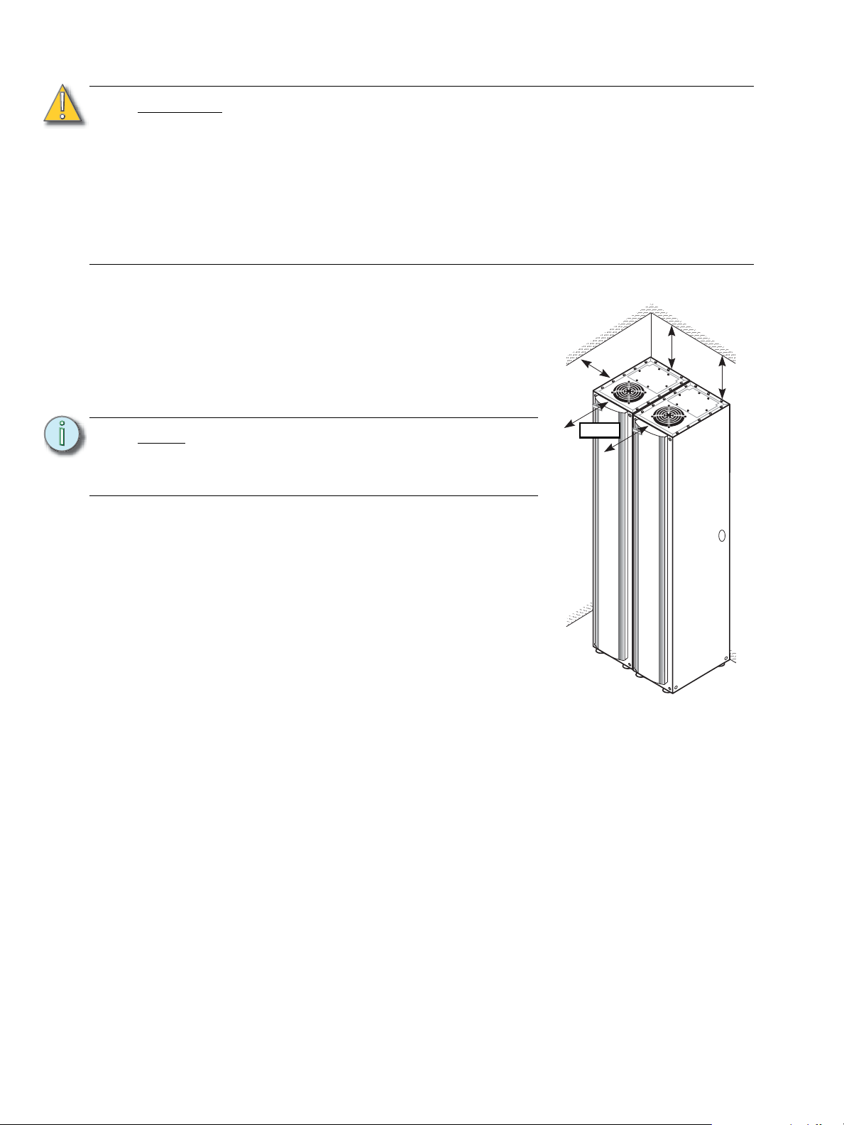
Figure 1: Sensor3 rack clearances
150mm
250mm
410mm
CAUTION:
A two-wire circuit with separate phase and neutral conductors is required for
every branch circuit that will be connected to the dimmer rack. Shared neutral
circuit arrangements are not recommended for phase-control dimming systems
due to harmonics and potentially elevated neutral currents in a shared neutral
arrangement.
For retrofit installations where shared neutral circuits are already installed, or track
lighting installations where the track has a shared neutral, consult ETC Technical
Services for rack installation guidelines.
The Neutral of the supply to the dimming system should have at least the same
cross-sectional area as the phase conductors
Where to Mount the Rack
Sensor3 dimmer racks require 25cm of top clearance
for proper airflow through the cabinet. To allow the door
to open sufficiently to install and remove modules,
install the rack with 41cm of front clearance and 15cm
clearance to the left of the door hinge from walls or
other equipment.
Note:
Additional Sensor3 racks of the same size are
the single exception to the 15cm left clearance
rule. They can be installed side by side without
problems.
Dimmer Room Requirements
• A main circuit breaker cabinet or other readily
accessible input power disconnect device.
• A clean (not dusty) temperature-controlled
environment
• Restricted public access to prevent tampering
• Soundproofing or performance area separation to
muffle ventilation fan noise
Please see Appendix A: Sensor3 CE Rack
Specifications, page 34, for environmental details.
Wire Routing
ESR3-12 racks are normally wall-mounted. ESR3-24
racks can be wall or pedestal mounted. ESR3-36 and
ESR3-48 racks are designed to be free standing.
Install racks with the CEM3 about 100cm from the floor. In ESR3-12 and ESR3-24 racks,
the CEM3 is in the bottom slot. In ESR3-36 and ESR3-48 racks, the CEM3 slot is in the
middle.
Sensor3 racks have access panels at the top and bottom, and conduit knockouts at the
side. Line and load wiring can enter from the top or bottom. Control cables can enter from
the top, bottom or side. Signal and power wiring must be run in separate conduits.
4 Sensor3 CE Rack (ESR3) Installation Manual
Page 13
Chapter 2
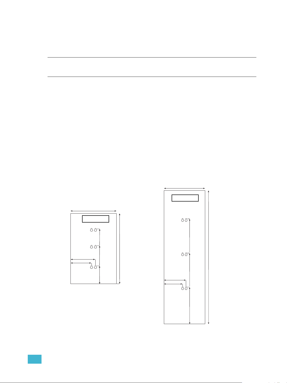
481mm
375mm
326mm
137mm
650mm
203mm
171mm
ESR3-12 rack
375mm
203mm
171mm
1213mm
925mm
616mm
306mm
ESR3-24 rack
Installation of Racks
Mounting the Rack
• ESR3-12 racks are normally wall-mounted.
• ESR3-24 racks can be mounted to a wall or floor-mounted on an optional pedestal.
• ESR3-36 and ESR3-48 racks are floor standing.
Mounting Racks on a Wall (ESR3-12 and ESR3-24)
The wall must be strong enough to hold the racks. Please see Appendix A: Sensor3 CE
Rack Specifications, page 34 for rack and module weights.
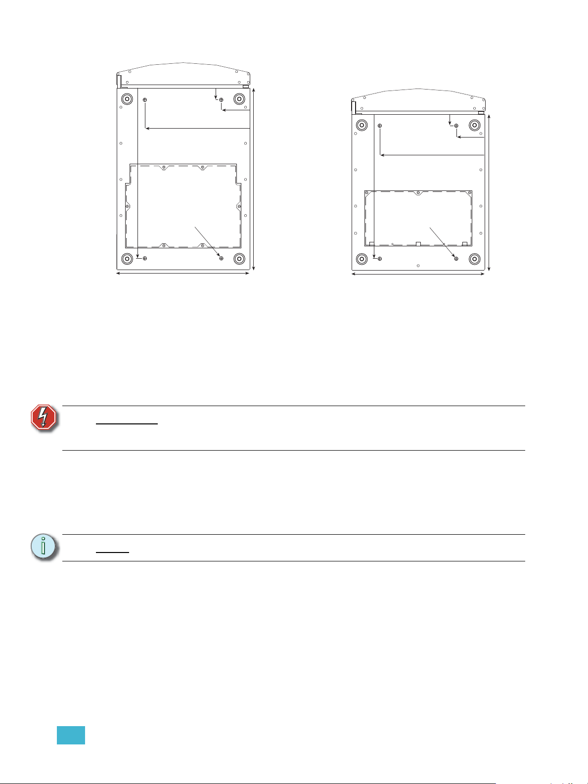
Step 1: Determine where your rack will be installed using Figure 1: Sensor3 rack
clearances on page 4 and use the appropriate diagram from Figure 2 to mark
your mounting holes.
Step 2: Use the mounting slot dimensions to mark the hole locations. You must supply
your own M10 mounting hardware.
Step 3: Drill the holes and install the hardware.
Step 4: Attach the rack to the wall.
Figure 2: ESR3-12 and ESR3-24 wall mount hole diagrams
2 Installation of Racks 5
Page 14
Installing ESR3-36 and ESR3-48 Racks on the Floor
Step 1: Determine where your rack will be installed using Figure 1: Sensor3 rack
clearances on page 4 and use the appropriate diagram from Figure 3 to mark
your mounting holes.
Note:
Step 2: Drill the holes and install your own M10 mounting hardware.
Step 3: Position the rack in the desired location.
Step 4: Adjust the leveling feet with an open ended 12mm spanner until the rack is level
Note:
Step 5: Secure the rack to the floor using your mounting hardware.
Sensor3 racks of the same size are the single exception to the 15cm left clearance
requirement. They can be installed side by side without problems.
and vertical.
Sensor3 installation racks are tall, narrow, and heavy. Use caution to keep racks
stable until the rack is secured to the floor or wall.
Pedestal Mounting an ESR3-24 Rack
Step 1: Use Figure 3 to mark the location of the ESR3-24 mounting holes. The ESR3-24
pedestal has the same floor mounting dimensions as the ESR3-24 rack.
.
Note:
Step 2: Drill holes or mount floor hardware and position the pedestal on them.
Step 3: Secure the pedestal base to the floor.
Step 4: Position the rack on the pedestal and align the mounting holes.
Step 5: Bolt the rack into place.
You must supply M10 mounting hardware. The pedestal has four mounting holes
into the floor and four securing the rack.
6 Sensor3 CE Rack (ESR3) Installation Manual
Page 15
Securing Sensor3 Racks to a Wall
ESR3-48 Floor mount hole diagram ESR3-36 / ESR3-24 Floor mount hole
Dia. 10mm
480mm
294mm
79mm
32mm
373mm
511mm
Figure 3: Hole diagrams for mounting racks to the floor
Dia. 10mm
404mm
294mm
79mm
32mm
373mm
436mm
Racks installed on the floor or a pedestal can also be secured to a wall for greater stability.
Step 1: Prepare the rack for floor or pedestal mounting (Installing ESR3-36 and ESR3-
48 Racks on the Floor, page 6 or Pedestal Mounting an ESR3-24 Rack, page 6).
WARNING:
Note:
Make sure the holes for the mounting hardware are located where the
hardware cannot come into contact with electrical wiring. Make all
modifications in accordance with your country’s electrical codes.
Step 2: Mark the locations for your securing hardware on the wall.
• For ESR3-12 or ESR3-24 racks, use the diagram in Figure 2 to determine
where you need to install your hardware.
• For ESR3-36 and ESR3-48 racks, put the rack in position and mark the holes
directly.
Step 3: Drill holes or install mounting hardware in the marked locations.
Step 4: Finish mounting the rack to the floor or pedestal.
Step 5: Attach the rack to the wall with your securing hardware.
Be sure to level your racks before marking the hole positions.
2 Installation of Racks 7
Page 16

Wall Mounting Racks Using Vibration Pads
Figure 4: Positioning a vibration pad
on a wall
Align the center of the fitting over the diagram
hole location and mark the position of the fitting
bolts
50cm
50cm
25cm 25cm
ETC Part# HW6111
Figure 5: Floor vibration pad
Center the fitting over the mount hole location
from the diagram and mark the positions for the
fitting hardware
ETC Part#
HW6109
38mm
38mm
Vibration damping fittings are available as an option
for wall mounted racks. The wall must be strong
enough to hold the racks. Please see Appendix A:
Sensor3 CE Rack Specifications, page 34 for rack
and module weights.
Note:
Note:
Be sure this mounting method complies
with your countries building and electrical
codes.
Step 1: Mark the hole locations on the wall from
Figure 2: ESR3-12 and ESR3-24 wall
mount hole diagrams on page 5.
ETC’s wall mount vibration pads (ETC
Part# HW6111) attach to racks with the
provided bolts that are slightly larger than
the top of the keyhole slots. The bolt works
fine installed in the lower portion of the slot,
but the rack will mount slightly higher
(approx. 10mm) than the diagram indicates.
Step 2: Align the center of the fitting over the hole locations from the diagram. Mark the
position for two fitting bolts for each vibration pad (the middle holes are
recommended).
Step 3: Drill the holes and secure the fittings to the wall. You must supply your own M10
mounting hardware.
Step 4: Remove the included bolt and washer from each vibration fitting.
Step 5: Position the rack on the wall so the centers of the vibration fittings align with the
wall mounting slots.
Step 6: Secure the rack to its vibration pad with the included bolts and washer.
CAUTION:
Floor Mounting Racks Using Vibration Pads
ESR3-36 and ESR3-48 racks can be floor mounted on
Note:
8 Sensor3 CE Rack (ESR3) Installation Manual
optional vibration damping fittings (ETC
Part# HW6109).
Step 1: Determine where your rack will be installed
Step 2: Use the appropriate diagram from
Unless the all mounting and connections are done in a flexible manner, the
effectiveness of the vibration pads will be reduced or completely negated. This
includes the use of at least 30cm of flexible conduit or flexible cable for all of the
electrical connections to the rack(s).
using Figure 1: Sensor3 rack clearances on
page 4.
Be sure this mounting method complies with
local building and electrical codes.
Level racks before marking the hole positions.
Figure 3: Hole diagrams for mounting racks
Page 17

to the floor on page 7 to mark your hole locations.
Step 3: Align the center of the vibration fitting over the hole locations from the diagram.
Mark the positions for two bolts for each vibration pad.
Step 4: Drill the holes and secure the pads to the floor. You must supply your own M8
mounting hardware.
Step 5: Remove the included bolt and washer from each vibration pad.
Step 6: Position the rack on the pads so the center holes of the pads align with the
mounting holes in the base of the rack.
Step 7: [Optional] If required, secure the rack to a wall using wall mount vibration pads
(ETC Part# HW6111). If the vibration pads have been requested for the
installation, they are included with the rack.
• Follow instructions from Securing Sensor3 Racks to a Wall, page 7 to drill
holes in the back of the rack for wall mounting.
• Mount the rack to the wall using the procedure from Wall Mounting Racks
Using Vibration Pads, page 8, above.
Step 8: Secure the rack to the pads with the included bolts.
CAUTION:
Unless the all mounting and connections are done in a flexible manner, the
effectiveness of the vibration pads will be reduced or completely negated. This
includes the use of wall vibration pads when mounting to the floor and at least
30cm of flexible conduit or flexible cable for all of the electrical connections to the
rack(s).
2 Installation of Racks 9
Page 18

Securing Multiple Racks (Optional)
Hole for bolting
racks together
(recessed)
Hole for bolting
racks together
Figure 6: Placement of rack connecting holes
Temporarily remove
six screws from this
area
Install the rack splice and
replace the screws to
secure it
Figure 7: Screws to remove to connect two racks
Multiple racks can be connected to each other for greater stability.
Note:
If you want to install the control cable through the side of the racks, you should
remove the side cable knockouts before connecting the rack.
Step 1: Use M8 spin lock bolts and lock nuts in the front and at the back to bolt the racks
together at the bottom.
Note:
The front bolt is difficult to reach – you may need a magnetic bolt-driver or socket
extension.
Step 2: (ESR3-36 and ESR3-48 only) Remove six screws from the tops of adjacent
racks, as shown below.
Step 3: (ESR3-36 and ESR3-48 only) Place a rack splice plate over the empty screw
holes and replace the screws you removed in Step 2 as shown above.
Repeat Steps 1, 2 and 3 until you have secured all the racks.
10 Sensor3 CE Rack (ESR3) Installation Manual
Page 19

Rack Cabling Access
Figure 8: ESR3 access panels
Bottom access panel
Top access panel
ESR3 racks have removable top and bottom access panels.
Conduit Connections
Step 1: Remove the desired access panel from the rack.
Step 2: Cut access holes in the top and bottom access panels.
Step 3: Install your cabling into the holes.
Step 4: Re-install the access panel so that there are minimal air gaps. See “Sealing Rack
Air Leaks” on page 28. for more information
.
WARNING:
Note:
Cutting holes in the rack plates in situ may introduce metal debris into the
dimmer cabinet.
Trunking or Wire Trough Connections
Step 1: Remove the desired access panels.
Step 2: Cut suitable openings to mate with the trunking or trough using a jigsaw or
hacksaw.
Step 3: Reinstall panel on to rack
Step 4: Install a fiche paper lining or grommeting material in the access panel opening.
Wire openings must have fittings or linings to protect cable insulation from
damage by sharp metal edges.
Step 5: Position the trunking or wire trough above the prepared opening.
2 Installation of Racks 11
Page 20

Connect Line Power Wiring
Figure 9: Line and Load Connections
L1
connections
Line Neutral
connections
L2
connections
Load Neutral
lug
L3
connections
Load Earth
lug (behind
phase lug)
IEC Connector
for NEFM
(optional)
ETC recommends routing line (feeder) cables first,
load neutral and load earth wires next, and load
phase wires last.
CAUTION:
Line and load wires used with Sensor3
dimming systems must be copper. Do not
use wire containing aluminium or other
metals.
CAUTION:
Dress wires neatly and avoid leaving extra
wire inside the rack. Too much clutter
(especially along the right side of the rack)
can restrict air circulation and reduce
cooling efficiency. If cabling interferes with
airflow during operation, the rack may shut
down due to overheating.
Preparing Line Feed Cable
Line cable and power wire should enter the rack
through the designated top and bottom access
points.
Line feed wires connect on the rack’s line phase,
neutral and earth bus bars. Each bus bar has one or
two 12mm studs to secure a lug connection for the
line feed wires. The installer must provide the line
feed connecting lugs.
Pull the line phase, neutral and earth cables to the
rack through the openings you prepared previously.
See “Rack Cabling Access” on page 11.
Line Earth
connections
Load Phase
lug
Step 1: Pull the line phase, Neutral and Earth
cables to the rack through the openings
you prepared previously.
Step 2: Cut the wires to length such that they
reach the correct stud
Step 3: Prepare the end of the wire and fit the
desired termination.
Step 4: Attach the lug to the correct phase,
neutral or earth stud as shown in
12 Sensor3 CE Rack (ESR3) Installation Manual
Step 5: Tighten the lugs to 59.5Nm.
Figure 9: Line and Load Connections on
page 12.
Page 21

Chapter 3
Figure 10: Line and
load wiring example
Dress and connect load
wires neatly without leaving
extra wire in the rack.
Double-height 50 amp lug
6/10/15/25 amp lug
Dual 15/25 amp lugs (fluorescent)
Switched
Control or
Dimmed
Figure 11: Load lug types
Land Load Wires
Land Load Wires
Each dimmer has three sets of lugs connected to phase,
neutral and earth. Phase and earth lugs are on the right side
of the rack, neutral lugs are on the left. Lugs can be single 6/
10/15/25 amp, paired 15/25 amp fluorescent, or doubleheight 50 amp.
Note:
CAUTION:
Step 1: Route the load wires to the rack(s).
Step 2: If using Multicore cable, strip back the sheath so
When using ED15AFRF modules connected to
dimmable fluorescent 3-wire ballasts, wire the top
lug in each slot to the ballast’s non-dimmed power
lead and the bottom lug to the dimmed ballast
control lead.
Dress and terminate wires neatly and avoid leaving
extra wire inside the rack. Too much clutter
(especially along the right side of the rack) can
restrict air circulation and reduce cooling efficiency.
If cabling interferes with airflow during operation,
the rack may shut down due to overheating.
Load wires should not cross between racks. They
should enter the rack in which they will be
terminated.
Phase and neutral load wiring must follow the same
conduit/path for each circuit.
3 Land Load Wires 13
Page 22

that phase, neutral and earth can be corrected to the relevant lugs as shown.
Figure 12: Load cable connection to lugs
Load Neutral (blue
wires) are landed on
load neutral lugs
attached to the main
neutral bus plate
Each dimmer’s load
lug set is at the same
height.
Load Phase
(brown wire)
Load Earth
(green wire with
yellow stripe)
The Right way
Insert the wire between the pressure plate and
the back of the lug and clamp the plate on top of
the wire.
The Wrong way
Don’t clamp the wire on top of the
pressure plate with the lug screw.
Pressure Plate
Lug Screw
Step 3: Fit load earth wires into the earth lugs as shown below and torque to the
recommended value from Table 1.
• Insert the wire under the pressure plate and tighten it onto the wire with the
screw. Do not clamp the wire directly under the screw.
Step 4: Fit load neutral wires into the neutral lugs in the same manner and torque to the
Step 5: Fit load phase wires into the phase lugs in the same manner and torque to the
WARNING:
CAUTION:
Step 6: Tighten all load connections to the torque specified in the table below.
14 Sensor3 CE Rack (ESR3) Installation Manual
Figure 13: Connecting lug wires
recommended value.
recommended value.
If any wire splices are required (none are recommended), they must be
made with a crimp-style butt-splice. Terminal block is NOT acceptable.
To prevent interference with cooling airflow, do not run load wires from one rack
through a different rack. See Sealing Rack Air Leaks, page 28 for more
information.
Table 1: Lug torque values
Cable size Torque (Nm)
2
1.5mm
2
2.5mm
2
4.0mm
2
6.0mm
2
10mm
2
16mm
4.0 Nm
4.0 Nm
4.0 Nm
4.5 Nm
4.5 Nm
5.0 Nm
Page 23

Cut Key Slots for Modules
Figure 14: Cutting Key Slots
Cut/remove for 25A module
Cut/remove for 50A module
Sensor3 dimming and control modules are easily slid into place by hand. Each module slot
is keyed to accept only a module with the correct current rating for the slot.
Cutting Key Slots for 25A and 50A Modules
Modules with current capacities higher than 15A are prevented from fitting into incorrect
slots by the module cutout bar to the left of the rack. If you have supplied a configuration
chart to ETC these should be cut out correctly for you; otherwise you will have to cut the
bar on site.
Step 1: Ensure power to the rack is turned off and the modules are removed
Step 2: Locate which slots will be fitted with 25A and 50A modules
Step 3: Using a pair of large wire cutters, open the required notch in the bar
• For 25A modules, open the top notch
• For 50A modules, open the bottom notch
CAUTION:
Ensure that the metal swarf created by cutting the key slots does not cause any
shorting within the rack. Clean the rack after cutting key slots.
3 Land Load Wires 15
Page 24

Converting Neutral Disconnect Slots
Figure 15: Removing a lug
Use a small flat screwdriver
to lift the lug tab enough to
release the lug from the strip
and pull it out.
Figure 16: Converting Neutral Disconnect lugs to use single pole dimmers
There are two classes of modules available for Sensor3 CE racks - modules which break
the neutral, such as RCD or ND modules, and single pole modules that do not. Normally
your rack will be configured by ETC at the factory for the correct module types, however if
you have a mixture of modules or you have not been able to supply details of slot
allocations you may need to configure some slots on site.
Step 1: Determine which dimmer slots you will be converting. You can convert either
individual slots or a three-slot strip at a time.
Step 2: Gently bend the neutral lug retraining tab out with a
small flat blade screwdriver until the lug releases and
you are able to pull it out. See Figure 15.
CAUTION:
Step 3: Use a flat blade screwdriver to loosen the threaded
Step 4: Repeat Step 2 and Step 3 for the other dimmer slot
Step 5: Install a Neutral lug jumper into the lugs and tighten
Step 6: Slide the jumpers into the plastic lug strip until the lug tab clicks into place.
Step 7: Secure the jumper to the thread on the Neutral bus bar using the provided
Repeat Steps 1 through 6 for any other lugs you want to convert
Lug catches will break if bent too far. Only bend the
catch until the lug releases.
inserts until the contact plates can slide out of both
lugs.
lug.
the threaded inserts.
M3x8mm screw.
16 Sensor3 CE Rack (ESR3) Installation Manual
Page 25

Installing Three-Slot Dimmer Lug Strips
Figure 17: Removing or installing a
Neutral lug strip
Step 1: Use a Phillips screwdriver to remove the two
screws securing the lug strip to the left side
of the rack.
Step 2: Remove the lug strip and replace it with one
containing a three-slot Neutral jumper.
Step 3: Secure the strip to the rack with the screws
you removed in Step 1.
Secure the jumper to the main Neutral bus PEM inserts
using the two screws provided with the jumper.
3 Land Load Wires 17
Page 26

18 Sensor3 CE Rack (ESR3) Installation Manual
Page 27

Chapter 4
Figure 18: Single Backplane
Figure 19: Dual Backplane
Control and Data Connections
Sensor3 racks support a variety of control and data connections on the CEM3 backplane.
CEM3 backplanes have connectors for:
• Two DMX512 Cables (Universes)
• External Panic Circuit Activation and Indication
• Remote Redundant Tracking selection switch (Dual Backplane Only)
• Ethernet Network
• Station Wiring
Dual and Single Backplane Differences
To use dual control modules your rack must be fitted with a dual tracking backplane. Racks
without dual tracking may have an empty second slot, or use the second slot to hold a
network switch. The exception is ESR3-12 racks, which only have space for a single control
module.
Racks with a dual backplane also have a three position switch which allows manual
switching of control of the rack to the top CEM3, the bottom CEM3, or for automatic
switching between the two.
4 Control and Data Connections 19
Page 28

Running DMX Cable to Racks
Figure 20: Side
data knockouts
1234567812345678
COM
n/c
n/c
n/c
n/c
n/c
n/c
n/c
n/c
n/c
n/c
Data + (Red)
Data - (Black)
From source
DMX A
If daisy-chaining to
another rack or
DMX device...
COM
Data + (Red)
Data - (Black)
From source
DMX B
If daisy-chaining to
another rack or
DMX device...
Figure 21: Stranded DMX Connection
Note:
Note:
Note:
If the system includes a Panic circuit, stations or Remote Tracking Selection, pull
the necessary wires with the data cables to all required racks.
Step 1: Remove the desired top, bottom or side conduit knockout
from the first rack on the left or right of the group of racks. See
Figure 20:Side data knockouts for knockout locations.
Step 2: Remove the 25mm side data conduit knockouts between the
first rack and the other racks in the group.
Using side knockouts for data cable conduit between racks is
recommended because it provides the most direct route
between CEM3 backplanes. You can use the top and bottom
openings if desired.
Step 3: Attach control cable conduit in the first knockout hole and the
knockouts between the remaining racks.
If you are installing control cable in racks that are joined
together, install IP20 rated conduit bushing into the knockout
holes between the racks
Step 4: Pull DMX512 cables through the conduit connection on the first rack and through
the connections between racks until the cable reaches the last rack in the group.
Leave 250-300mm of slack at each rack’s backplane.
DMX Termination - Screw Terminals
Step 1: Terminate the cable(s) as shown below
using the termination kit included with
the rack (in the rack door). Refer to the
guide included with the kit for detailed
termination instructions.
Step 2: Connect the DMX header to the
relevant socket on the rear of the
backplane.
Note:
DMX Termination - IDC Connection
Only one screw header is supplied with
the rack. You may use the header to
terminate DMX A and DMX B to “PASSTHRU” if needed.
Step 1: Terminate the cable as shown below
using an IDC termination kit. Note that
an IDC termination kit is not included
20 Sensor3 CE Rack (ESR3) Installation Manual
Page 29

with the rack and should be ordered separately.
12345678 1234567812345678
n/c
n/c
COM
Data +
Data +
Data -
Data - ORG
W/ORG
BRN
GRN
W/GRN
BLU
W/BLU
W/BRN
COM
Data +
Data - ORG
W/ORG
W/BRN
COM
Data +
Data - ORG
W/ORG
W/BRN
ORG
W/ORG
BRN
GRN
W/GRN
BLU
W/BLU
W/BRN
COM
If daisy-chaining to
another rack or
DMX device...
DMX A
Thru
DMX B
Thru
From source
DMX A
From source
DMX B
Figure 22: IDC DMX Connection
Step 2: If needed, terminate both the outgoing cables into the third header, “PASS-
THRU”. This header is located below the primary DMX headers and has both the
DMX A and DMX B connections available as shown above.
Setting DMX Termination
After completing data connections you must properly terminate each DMX line using the
termination DIP switches on the CEM3 backplane. Data termination eliminates signal
“reflections” at the end of the network that interfere with network functions. Each DMX line
should have termination turned On at the last network connection.
Step 1: Locate the termination DIP switches on the CEM3 backplane.
Step 2: Using the label on the backplane to match data connections to the associated
termination DIP switches.
Step 3: Set the termination switches to On (Up) or Off (Down) depending on the
connection status:
• If the connection is jumpered to another rack or device, turn termination Off.
• If the connection ends at the rack, turn termination On.
Note:
• If a data connector is not used, either setting is acceptable.
The termination switches should not be set to the “RDM” position unless
recommended by ETC.
4 Control and Data Connections 21
Page 30

Running Ethernet to Racks
Figure 23: Ethernet connections with a NEFM
Ethernet
Ethernet
Sensor3 racks
Congo
CEM3
NEFM
CEM3
Figure 24: Ethernet connections with an external network
Congo
Sensor3 racks
Ethernet Ethernet
CEM3 CEM3 CEM3 CEM3
Sensor3 racks use Ethernet for communication with each other and sometimes for
communication with the lighting console. It is therefore important that all racks are linked
via Ethernet. This may either be done using an NEFM (Network Electronics Filler Module A network switch built into the lower slot of one of the racks) or using an external network
hub or switch.
Ethernet with a NEFM
If one of your racks is supplied with a NEFM, run a CAT5 cable from each rack to the rack
with the NEFM. You may make the connection either using prefabricated CAT5 network
cables, or using CAT5 cable and the termination kits provided.
Ethernet with an External Network
If the system has an external network, connect each rack to the external hub or switch using
CAT5 cable. A network termination kit is provided with each rack (in the door) for the
Sensor3 rack. You may need to provide termination at the network switch, e.g. a patch
panel.
22 Sensor3 CE Rack (ESR3) Installation Manual
Page 31

Ethernet Network Termination - RJ45 Connector
Maintained
Closure
To trigger Panic,
use a
To external
indicators
(such as a
lamp or relay)
+24Vdc
(max 25mA
each)
To external
indicators
(such as a
lamp or relay)
+24Vdc
(max 25mA
each)
For Panic SEND/RTN:
NO - Normally Open closure
Disabled - Panic Disabled
NC - Normally Closed closure
To Sensor3
compatible
stations
SEND
Figure 25: Backplane Panic Connections
Step 1: Follow the directions provided in the Ethernet Termination Kit to terminate the
incoming CAT5 cable in the RJ45 UTP connector in the surface mounting box.
The kit is included with the dimmer rack door. Use the instructions provided with the kit for
proper Category 5 cable termination.
Step 2: The surface mount box should be installed with the double-sided tape inside the
rack.
• ESR3-36, ESR3-48: To the underside of the CEM3 backplane bracket.
• ESR3-12, ESR3-24: To the bottom of the rack behind the backplane.
Step 3: Use the provided male-to-male Ethernet patch cable to connect the surface
mounting box female RJ45 connector to the female RJ45 connector on the
CEM3 backplane.
Panic Circuit Connections (Optional)
Sensor3 racks can connect to an external Panic circuit if desired. Panic can be triggered by
a normally open or normally closed contact. The racks can also provide a feed to a lamp or
LED to indicate whether panic is active.
Panic Circuit backplane connection
Step 1: Pull two 1.5mm2 wires from your Panic contact location to the CEM3 backplane
through the data cable conduit or trunking. See Running DMX Cable to Racks,
page 20 for data conduit installation details.
Step 2: Connect the wires to the connector on the CEM3 backplane. Connect the Panic
contact input between “PANIC RTN” and “PANIC IN”.
Step 3: Optionally, connect an external panic indication lamp between “PANIC OUT” and
“COM”. When panic is active, there will be a supply of +24VDC between “PANIC
OUT” and “COM”, with a maximum current draw of 25mA.
Step 4: Set the switch on the backplane to indicate the contact type: Normally Open (NO)
or Normally Closed (NC).
4 Control and Data Connections 23
Page 32

Dual Tracking Remote Select Switch connection (Optional)
1 2 3 4+24Vdc COM
J12
Figure 26: J12 Dual Tracking remote connector wiring
Header at the top of the
backplane PCB
Orange remote tracking header.
Pin 1 is the pin closest to the phase
bars (left side of the rack as you look
in)
Position A - Primary
Position B - Secondary
An indicator lamp
50mA 24Vdc max for
internal power supply
If desired, a remote switch can be wired to the CEM3 backplane to control CEM3 selection
in racks equipped with ETC’s Redundant Tracking CEM3 option.
Note:
Note:
You must supply your own enclosed single-pole double-throw center-off switch to
install a remote select switch. You may optionally use an external 24V DC power
supply, or use the power supply from the rack backplane.
2
Step 1: Pull 1.5mm
wires between your remote switch and the CEM3 backplane
through the data cable conduit. See Running DMX Cable to Racks, page 20 for
data conduit installation details. For systems with no requirement for remote
tracking status indication three wires are required, otherwise four wires will be
required.
Step 2: Connect the remote switch wires to the J12 connector on the rear of the
backplane.
The J12 connector is a removable plug header and is easier to wire when it is
disconnected from the backplane in an installed rack.
Step 3: Wire the remote switch and indicator to the J12 connector according to
Figure 26.
24 Sensor3 CE Rack (ESR3) Installation Manual
Page 33

Station Connection (Optional)
to stations
Figure 27: Connection of station wiring
Sensor3 racks support ETC’s range of stations. The station network should be wired in
Belden 8471 or an equivalent cable. Stations are topology-free. Wiring may be bus, star,
loop, home run or any combination of these.
B
e
l
d
Connecting Station Wiring
Step 1: Cut the Belden 8471 cable so that a 20cm tail extends from the edge of the
backplane.
Step 2: Strip 18cm of the outer jacket off.
Step 3: Strip 6mm of insulation from the ends of the Belden 8471 wires.
Step 4: Insert the white wire into “STATION +” terminal on the backplane board. Tighten
the screw firmly.
Step 5: Insert the black wire into “STATION -” terminal on the backplane board. Tighten
the screw firmly.
e
n
8
4
7
1
SEND
Connect ESD Ground
For installations with data runs of Belden 8471 installed in earthed metal conduit there is no
need to run and terminate an additional ESD drain wire. For installations not installed in
earthed metal conduit, run a 2.5mm
the instructions below for termination.
Step 1: Locate the earth terminal bar to the right of the rear of the dimmer rack.
Step 2: Strip 6mm of insulation from the ends of the 2.5mm
Step 3: Insert the earth wire into an available earth lug and secure with the set screw.
2
ESD drain wire with the Belden 8471 cable. Follow
2
ESD drain wire.
4 Control and Data Connections 25
Page 34

26 Sensor3 CE Rack (ESR3) Installation Manual
Page 35

Chapter 5
Finishing Installation
The steps in this chapter should only be performed by, or after receiving approval from, an
authorised ETC representative.
Check Backplane DIP Switches
The backplane of your rack features a set of eight DIP switches allowing configuration of
the rack type. The CEM3 reads these DIP switches to determine the rack type, phasing and
available modules. Compare the position of these DIP switches to the table below and, if
necessary, set them to the correct position using a jewellers screwdriver.
Use the following chart to determine your required DIP switch settings:
DIP Switch Number
Rack Model
ESR3-12 On On
ESR3-12N On On On
ESR3-12AF On On On
ESR3-12AFN On On On On
ESR3-24 On On
ESR3-24N On On On
ESR3-24AF On On On
ESR3-24AFN On On On On
ESR3-36 On On
ESR3-36N On On On
ESR3-36AF OnOnOn
ESR3-36AFN On On On On
ESR3-48 On
ESR3-48N On On
ESR3-48AF On On
ESR3-48AFN On On On
12345678
Energising the System
You need ETC approval to apply power to your dimming system. Wiring errors in
unauthorised installations may endanger operators or cause system damage and failure.
WARNING:
CAUTION:
Do not attempt to energise the system without proper approval. Energising
the system without ETC approval may result in serious injuries.
Energising your system without ETC approval may result in equipment damage
that may void your warranty!
Contacting ETC
To obtain ETC approval or for referral to an authorised ETC representative, contact ETC
as shown in Contacting ETC, page 2.
5 Finishing Installation 27
Page 36

Sensor3 Installation Checklist
Table 2: Loose parts shipped with ESR3 rack doors
Quantity ETC Part Number Descriptions
1 4100A1012 DMX Cable Prep Kit w/ 1 screw connector
1 4101A2003 Ethernet Term Kit
1
7051A2009(ESR3-48/36/24)
7051A3006(ESR3-12)
Rack Bottom Hinge
1 7051A3006 Door Top Hinge
2 HW253 Screw 6-32x3/8 truss SS
3 HW757 Pin, Taper 5/32x1.0
6 HW327 Washer, Flat #8 .188x.375x.049 SS
1 HW8202 Door Key
1 7051A4116 Beacon Acrylic
A checklist is provided in Appendix B: Sensor3 Installation Checklist, page 35. Following
this checklist will help ensure that your Sensor3 system operates reliably and without
problems. The checklist is a summary version of the steps in this chapter.
Sealing Rack Air Leaks
After you have installed all conduit, trunking and cables to the rack and connected all wiring,
you must seal any air leaks in the rack cabinet created during the installation process. Use
urethane aerosol foam to fill air gaps.
Step 1: Seal all access holes.
Step 2: Re-install access panels removed during installation, or completely cover their
openings with fiche paper and urethane aerosol foam or duct seal.
Step 3: Seal any air gaps caused by bent access panels.
Step 4: Fill in any gaps inside partially filled wiring conduit or trunking.
Step 5: Fill in other gaps or holes in the cabinet created during installation.
CAUTION:
Air leaks can cause dimmer racks to overheat during operation and shut down.
Attaching the door
All Sensor3 racks are delivered with the doors separated. This improves access to the rack
interior for wiring and other installation work. Some loose door installation parts are bundled
with the doors as detailed below in Table 2.
When interior wiring is completed, attach the rack door. Do not operate your dimmer rack
without a door installed.
CAUTION:
Dimmer rack doors filter and regulate ventilation airflow. Operating without the
door can contaminate the rack interior with dust and cause rack modules to
overheat.
Step 1: Insert the top hinge into the slot on the top of the rack and attach it to the frame
28 Sensor3 CE Rack (ESR3) Installation Manual
Page 37

with two Phillips head screws (included).
Top hinge being inserted Top hinge in place
Bottom hinge
being inserted
Bottom hinge
in place
Bottom hinge
in place
Bottom hinge
being inserted
Figure 28: Attaching the top door hinge
Step 2: The bottom hinge on the ESR3-12 is a different design from the one used on the
ESR3-24, ESR3-26 and ESR3-48.
• ESR3-12 – Insert the bottom hinge into the slot on the bottom of the rack and
attach it to the frame with two Phillips head screws (included).
Figure 29: Attaching the ESR3-12 bottom hinge
• ESR3-24, ESR3-36 and ESR3-48 – Remove the large Phillips head screw,
insert the hinge into the slot and secure it by replacing the screw.
Figure 30: Attaching the ESR3-48 bottom hinge
• Drive the narrow end of one taper pin into the bottom of the door. Put the
5 Finishing Installation 29
Page 38

taper pin through the washers and into the hole on the lower hinge.
ESR3-48 lower hinge ESR3-12 lower hinge
Door
Taper pin
Door
Taper pin
Washers
Washers
Taper pin
Figure 31: Installing the bottom taper pin
Step 3: Hold the door in place and insert the other taper pin, narrow end down, through
the top hinge and washer.
Figure 32: Installing the top taper pin
Step 4: Take the Sensor3 beacon block, insert it through the slot on the upper left corner
of the door and secure it with two Phillips head screws (included).
Figure 33: Installing the beacon block
30 Sensor3 CE Rack (ESR3) Installation Manual
Page 39

Checking Rack Installation before Installing Modules
AF Card Addressing
Card 1
Card 2
Card 3
Card 4
S
W
1
S
W
2
S
3
S
1
ESR3-12
ESR3-24
ESR3-48
2
3
4
Sensor+
O = Switch in down position
ESR3-36
Figure 34: AF3 Card Addressing
It is a good idea to check the installation before applying power to the rack.
Before Applying Power to the Rack
WARNING:
RISK OF ELECTRIC SHOCK! Power must be turned OFF when you perform
this procedure.
Step 1: Clean out dust, metal scraps or other debris from the rack interior.
• ETC recommends vacuuming the rack interior before installing modules.
Step 2: Check for loose connections, bare wires or damaged insulation.
Step 3: Correct air leaks caused by misaligned or removed panels, empty screw holes,
or conduit openings.
Step 4: Remove the cardboard protective cover from the top fan grille. Spin the top
cooling fan to be sure it is not obstructed.
Step 5: Check resistance between phases, Neutral and Earth for short circuits:
a: Phase to Phase; resistance should be 500k ohms or higher
b: Phases to Earth; resistance should be 500k ohms or higher
c: Neutral to Earth; resistance should be very close to 0 ohms
d: Phases to Neutral; resistance should be 500k ohms or higher
Installing Advanced Features (AF) Cards (Optional)
If your rack is an Advanced Features
rack, it should be supplied with AF cards
from the factory. Normally these will be
pre-fitted for you, however if you do need
to fit the cards use the following
procedure:
W
W
4
Step 1: Address your AF cards using
the DIP switches as shown in
Figure 34
Step 2: Locate the AF card slots at the
right hand side of the rack
Step 3: Insert the AF cards into the
slots and push until securely seated, a tangible click occurs when fully inserted.
Installing the Control Electronics Module (CEM3)
Step 1: Inspect the CEM3 for loose components or other shipping damage.
Step 2: Slide the CEM3 into the rack.
Step 3: Push on either side of the CEM3 until it is flush with the front of the rack. Do not
push in the centre as you may cause damage to the display.
5 Finishing Installation 31
Page 40

Installing Dimmer Modules
Step 1: Inspect each dimmer module for loosened components or shipping damage.
Step 2: Slide dimmer modules into the rack. If you are installing a mix of module types,
consult the included project drawings for the correct module order.
Step 3: Push each module into its slot until it is flush with the front of the rack.
Installing Module Locking Bars
CAUTION:
The module locking bars to the left of the rack are provided to prevent module removal
without use of a tool. It is an important requirement that they are fitted once installation is
complete.
Step 1: Slacken off the three Phillips screws that secure each module locking bar in
Step 2: Slide the module locking bars to the right fully, so that they overlap the edge of
Step 3: Tighten the Phillips screws fully and check that modules cannot be removed.
The module locking bars should always be installed once installation is complete.
Failure to do so leaves the end user open to risk of electric shock.
place.
the dimmer modules.
Completing Installation
Once you have completed installation, please fill in Appendix B: Sensor3 Installation
Checklist, page 35 for the system and return it to ETC. The system will then be covered
under the ETC warranty programme.
32 Sensor3 CE Rack (ESR3) Installation Manual
Page 41

Testing an Installed Sensor3 Rack
After finishing installation, use this procedure to perform a functional check.
Note:
Step 1: Make sure power is disconnected at the main circuit breaker.
Step 2: Open the door and set all the dimmer module circuit breakers to Off.
Step 3: Remove the CEM3 and set the test switch to TEST.
CAUTION:
Step 4: Replace the CEM3 and close the door.
Step 5: Apply power at the main circuit breaker
WARNING:
Step 6: Observe the rack for obvious faults:
Go over the Sensor3 installation checklist in Appendix B: Sensor3 Installation
Checklist, page 35 before energising the rack.
Caution: With the test switch on TEST, all dimmers drive to full output. Your power
supply may not have enough capacity to operate the rack at full output. To avoid
tripping your main circuit breakers, make sure you have set all dimmer module
circuit breakers to Off before applying power.
.
3-Phase Mains voltage is present inside the rack during this procedure. Do
not remove rack modules when power is applied.
• Flashing Sensor beacon
• Any indication of shorting or burning from rack components
Checking individual dimmer operation
Step 1: Open the dimmer rack door.
Step 2: Set one dimmer module circuit breaker to On and check these functional
indications:
• Signal LEDs on the dimmer modules lit
• The dimmer’s lighting loads are on (if visible)
• The rack cooling fan is running
• Dimmer hum increases slightly
Step 3: Set the circuit breaker to Off, and repeat Step 2 with each dimmer module in the
rack.
If all indications are normal after testing the dimmer modules, the rack is functional.
Step 4: Remove power at the main circuit breaker.
Step 5: Open the rack door, remove the CEM3 and set the Test switch to NORM.
Step 6: Replace the CEM3 and close the rack door.
Step 7: An Authorized Service Center (ASC) may now configure the CEM3 processor(s)
and test the dimming system using the facility control system.
Step 8: Deliver all ETC documentation to the system operator.
5 Finishing Installation 33
Page 42

Appendix A
Sensor3 CE Rack Specifications
All of the rack specifications apply to all of the ESR3 series
of racks unless otherwise noted.
General
Racks available in four sizes
ESR3-12 12 modules, 24 dimmers maximum
ESR3-24 24 modules, 48 dimmers maximum
ESR3-36 36 modules, 72 dimmers maximum
ESR3-48 48 modules, 96 dimmers maximum
Dual density (two dimmers per module) and single density
dimmer modules available
Environmental
Operating temperature: 0-40C / 32-104F
Dimmer room HVAC systems must at all times maintain the
specified ambient temperature at the dimmer rack.
Dimming systems operating within 10 degrees C of the
upper or lower temperature limits must strictly follow
installation and operation guidelines to operate reliably.
Relative humidity: 30-90% non-condensing
Altitude: Below 2000 metres.
Mechanical
Rugged 16-gauge steel construction
Fine-textured, scratch-resistant, epoxy paint
ESR3-12 uses wall mount installation
ESR3-24 can be wall or pedestal mounted
ESR3-36 and ESR3-48 are floor mounted
Top and bottom cabling access through removable panels
Screwdriver required for module removal or installation
Keyed module slots prevent insertion of inappropriate
module types
Front access to all wiring and terminations
Full height locking door
Electrostatic air filter easily removed from door for periodic
cleaning
High efficiency cooling system with airflow sensor
High visibility LED status beacon
Electrical
ESR3 racks accept:
Single phase 230V AC (3-wire)
ESR3-36: restricted to a max.600A across all circuits
ESR3-48: restricted to a max. 800A across all circuits
Three phase 230/415 V AC (3-wire)
Line feed frequencies from 47-63Hz
Maximum current ratings:
ESR3-12 – 200 amps per phase (3 phase max.)
ESR3-24 – 400 amps per phase (3 phase max.)
ESR3-36 – 600 amps per phase (3 phase max.)
ESR3-48 – 800 amps per phase (3 phase max.)
These are absolute maximum current ratings. You may use
less dependant on the type and number of dimmer
modules.
Operational Voltage (U
Insulation Voltage (U
Impulse Withstand Voltage (U
Short-circuit current: 10kA Minimum (Consult Factory)
Degree of Protection: IP20
Types of Electrical Connection: W.W.W
): 230V +/-10% (3p + N + E)
e
): 400V
i
): 4000V
imp
EMC Environment: 1
Pollution Degree: 2
Complies with Low Voltage Directive 73/23/EC
Electromagnetic Compatibility Directive 89/336/83/EC
Complies with all applicable European
Directives and associated Standards for
product safety and electromagnetic
compatibility.
Control
Sensor3 Control Electronics Module (CEM3) electronics
Redundant Tracking of dual control modules available in
ESR3-24, ESR3-36 and ESR3-48
Single Ethernet control signal input
Two DMX512 inputs
Standard diagnostic reporting
Options
Advanced Features™ dimmer-specific load and diagnostic
reporting (included with ESRAFN3 racks)
Vibration reduction kits available for all racks
SSSH Hood for noise reduction
Empty Rack Weights
Model Weight (kg)
ESR3-12 31
ESR3-12 Door* 5
ESR3-24 60
ESR3-24 Door* 8
ESR33-6 75
ESR3-36 Door* 11
ESR3-48 113
ESR3-48 Door* 14
* Racks ship with door unattached, but in same crate.
Installed Rack Weights*
Model Weight (kg)
ESR3-12 66
ESR3-24 128
ESR3-36 176
ESR3-48 247
Typical - ED15 modules (2.5kg/slot)
Refer to module datasheets to calculate total rack weight for
other module types
Load Wiring Lug Capacity
Connection Wire Size
6/10/15A, 25A and 50A lugs 16mm
2
Max.
Rack Dimensions
Installation Rack Dimensions - Including Door
Model Height (cm) Width (cm) Depth (cm)
ESR3-12 65 37.5 42.5
ESR3-24 124 37.5 50.5
ESR3-36 170.5 37.5 50.5
ESR3-48 217 37.5 58.1
34 Sensor3 CE Rack (ESR3) Installation Manual
Page 43

Appendix B
Sensor3 Installation Checklist
CAUTION:
Job Number
Job Name
Rack of
Place a tick in each box to confirm item has been
checked and is OK. Write NA if Not Applicable.
This checklist is for use by authorised ETC trained personnel when energising
ETC Sensor3 racks. Do not attempt to energise a Sensor3 system unless you are
authorised and qualified to do so.
Beforehand
All material on site. Advise ETC of shortages
ASAP.
Electrical Contractor wiring OK
Confirm time and personnel for training.
DMX
Belden 9729 and ETC specified cables.
Daisy chain DMX.
Termination DIPs set correctly
Measure DMX termination from far end
Phase-Phase high impedance (>500k ohms)
Load-Neutral impedance > 1 ohm: no “shorts”
Rack clear of dust and debris
Dimmer modules: Chokes tight, hardware
tight, circuit breakers OK
Install dimmer modules
Install CEM3s
End User Training
Who received end-user training?
Contact ETC to return unused/defective
goods
Detail any open items
Ethernet
Network star topology and using CAT5 or
better cable
Longest ethernet Run < 100m
Cable correctly terminated
Rack - Power Off
Top/bottom access plates in place and air
gaps sealed
Side plates in place and air gaps sealed
All air gaps, connections to conduit, and
trunking sealed
All bolts tightened to specification
Rack bolted to floor or wall
Neutral per load, no floating neutrals/earths
in system
All load wires and lugs tight
Fan spins freely
Phase-Earth high impedance (>500k ohms)
B Sensor3 Installation Checklist 35
Page 44

Appendix C
Figure 35: Emergency Module Circuit
Module Circuit Breaker
Dimming or Relay Circuit
Dimmed or Switched Output
Constant Output
Figure 36: Emergency Module Connections
Constant live
line is landed
on the neutral
lugs
Dimmed or
switched line is
landed on live
lugs
Emergency Modules
About Emergency Modules
Sensor3 CE Emergency modules provide two live outputs, one of which is dimmed or
switched, and one of which is live whenever the breaker is turned on. This allows the
modules to control battery backed lighting which requires a constant and a switched or
dimmed feed.
There are two varieties of Emergency Module - ED15AFE (15A Dimmer), and
ER15AFE(15A Relay). They are painted red for easy identification.
Connection
The constant output from the module is connected to the neutral lugs at the left of the rack.
Therefore, unlike neutral disconnect modules, emergency modules provide a live output at
these lugs, not a neutral connection. There is no neutral disconnect or RCD version of the
emergency modules.
Step 1: Locate the slot where the Emergency module is to be fitted.
Step 2: Terminate the outgoing dimmed line to the terminals at the right hand side of the
Step 3: Terminate the outgoing constant feed line to the terminals at the left hand side of
Step 4: Terminate the outgoing earth to the earth bar terminals.
rack.
the rack.
36 Sensor3 CE Rack (ESR3) Installation Manual
Page 45

Step 5: Terminate the neutral as described below dependant on your rack type.
CAUTION:
It is important to correctly identify the Constant Live, Dimmed Live and Neutral
wires, as incorrect termination can cause damage to the fixture and/or dimmer
rack.
Single Pole Racks
For racks which have neutral jumpers fitted, the neutral of the load fed by the emergency
module should be connected to the neutral terminal of an adjacent module.
Neutral Disconnect Racks
In racks without neutral jumpers (Neutral Disconnect racks) the neutral of the load should
not be connected to another load’s neutral terminal. This can cause unwanted tripping of
RCD modules. Instead, an auxiliary neutral terminal must be fitted to the neutral plate and
the loads should be connected to the terminal. If your rack was ordered with Emergency
Modules the auxiliary neutral terminal should be factory fitted. If you require an auxiliary
neutral terminal, please contact ETC as shown using the details in Contacting ETC, page 2.
C Emergency Modules 37
Page 46

Page 47

Page 48

Corporate Headquarters
London, UK
Rome, IT
Unit 26-28, Victoria Industrial Estate, Victoria Road, London W3 6UU, UK Tel +44 (0)20 8896 1000 Fax +44 (0)20 8896 2000
Via Pieve Torina, 48, 00156 Rome, Italy Tel +39 (06) 32 111 683 Fax +44 (0) 20 8752 8486
Holzkirchen, DE
3031 Pleasant View Road, P.O. Box 620979, Middleton, Wisconsin 53562-0979 USA Tel +608 831 4116 Fax +608 836 1736
Ohmstrasse 3, 83607 Holzkirchen, Germany Tel +49 (80 24) 47 00-0 Fax +49 (80 24) 47 00-3 00
Hong Kong Room 1801, 18/F, Tower 1 Phase 1, Enterprise Square, 9 Sheung Yuet Road, Kowloon Bay, Kowloon, Hong Kong Tel +852 2799 1220 Fax +852 2799 9325
Service:
(Americas) service@etcconnect.com
Web:
www.etcconnect.com
7144M2100
Rev F Released 2013-05
Copyright © 2013 ETC. All Rights Reserved. Product information and specifications subject to change.
(UK) service@etceurope.com (DE) techserv-hoki@etcconnect.com
(Asia) service@etcasia.com
 Loading...