

Page 1

Source 4WRD II
HPL to LED Retrofit (UL)
Installation and User Manual
Versio n 1.1 .2
Part Number: 7067M1230-1.1.2 Rev A
Released: 2020-02
Page 2

To view a list of ETCtrademarks and patents, go to
etcconnect.com/ip. All other trademarks, both marked and not
marked, are the property of their respective owners.
ETC intends this document, whether printed or electronic, to be
provided in its entirety.
Page 3

Table of Contents
Introduction
Help from ETC Technical Services
Safety
Retrofit the Fixture
Wire the power connector(if needed)
Remove Incandescent Lamp Housing
Install the Source 4WRD II Retrofit
Install the Fixture
Attach C-clamp and Safety Cable
Connect Cables
Configure the Fixture
1
2
3
6
6
7
8
10
10
11
14
RDMValues
Focus the Fixture
Set the Z-adjustment
Adjust the Yoke Position
Shape the Beam
Source 4 WR D II I nstallatio n and User Man ual i
14
15
15
16
17
Page 4

Troubleshoot the Source 4WRD II
18
Clean and Maintain the Fixture
Clean the Fixture
Store the Retrofit
Clean the Lenses
Clean the Reflector
Clean 5° and 10° Polymer Lenses
19
19
19
20
21
22
ii Source 4 WR D II I nstallatio n and User Man ual
Page 5
Introduction
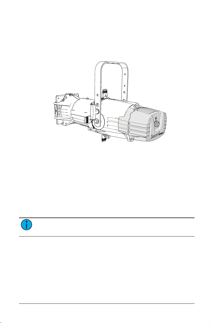
Source 4WRD II
LED retrofit kit,
shown installed
on a Source Four
fixture body
•
•
The So urce 4WRDII LED is a replacement for a standard Source Four
bu rner ass embly. It con verts the HPL source to a wh ite-l i ght LED and
provides a s ignificant red uction in power co nsumptio n.
The fo llowing So urce 4WRD II options are available in 80 CR I , 90 CR I
(Gallery), and 90 CRI Daylight (Gallery) variants :
Source 4 WR DII LED retrofit kit: Used to modi fy an existing Sou rce
Four HPL incandes cent fixture to a white LED fi xture. The Source
4WRDII LED can also be used with the Source 4 WR D PAR or PAR Nel
Fixture B o dy to create a Source 4 WR D II PAR or PAR Nel fixture. For
more i nformati on, vis i t etcco nnect.co m.
Source 4 WR D II Li g ht En g ine: Co mbin es the Source Fo ur
in candescen t fixtu re bo d y with the So urce 4WRDII LED. Availab le
on ly with 80 CRI and 90 CRI (Gallery) variants .
Note:
The So u rce 4WRDI I LED retro fit kit is no t co mpatibl e wi th
Source Fou r LED, Fres nel, PAR, PARNel, or jr fixtures.
Source 4 WR D II I nstallatio n and User Man ual 1
Page 6

Help from ETC Technical Services
•
•
•
If you are having difficulties and yo ur pro b lem i s no t addres s ed by this
do cu ment, try the ETC suppo rt web site at supp ort.etcco n nect.co m or the
main ETC website at etcconnect.com. If non e of these resou rces are
su fficient, con tact ETC Tech n ical Services d irectly at one o f the offi ces
id entifi ed bel ow. Emergency service is available from all ETC o ffices
ou tsid e of normal bu siness h o urs .
When calling for hel p, take these steps first:
Prepare a detailed descri ptio n of the problem
Go near the eq uipment for troubl esho otin g
Find your n o tification number if yo u have called in p revi ously
Americas United Kingdom
ETC, Inc . ETC L t d
Technic al Servic es Department Technic al Servic es Department
3031 Pleasant V iew Road 26-2 8 Victo ria Indust r ial Estate
Middleton, WI 53562 Vict oria Road,
800- 77 5-4382 (USA, toll- f r ee) London W3 6UU Eng land
+1- 60 8 831- 4116 +44 (0)20 8896 1000
service@ et c connec t .c om techser vltd@ et cconnect.c om
Asia Germany
ETCAsia ETC G mbH
Technic al Servic es Department Technic al Servic es Department
Room 18 01, 18/F Ohmstrasse 3
Tower 1, Phase 1 Enterpr ise Squar e 83607 Holz kir chen, Ger m any
9 Sheung Yuet Road +49 (80 24) 47 00-0
Ko wloon Bay, K owloon, Hong K ong techser v-hoki@etcc onnect .com
+852 2799 1220
techser vasia@ et cconnect.c om
France
ETC F r ance
Zone Urbaparc Bât iment E
6 Boulevard de la Libérat io n
Saint - Denis, 93200
+33 1 4243 3535
techser vltd@ et cconnect.c om
2 Source 4 WR D II I nstallatio n and User Man ual
Page 7

Safety
•
•
•
•
•
•
The So urce 4WRD I I fixture is intended for professi o nal use on ly. Read the
enti re manual before u sing thi s equipmen t.
WARNING: Note the following safety warnings before use:
Do not mount the fixture on or near a flammable
surface.
Do not use this fixture with a damaged power lead. If
the power lead (cord set) is damaged, it must be
replaced.
Mount and support the fixture only by the primary
suspension holes in the yoke.
Suspend the fixture from a suitable structure using only
hardware rated for the weight of the fixture.
In addition to primary suspension, attach a safety cable
(ETC Model 400SC or other approved safety cable or
device) to the fixture housing. An appropriate
attachment point (hole) is provided in the protruding
tab on the fixture housing.
Disconnect the unit from power and DMX and allow the
fixture to cool before removing or installing accessories,
and before all cleaning and maintenance.
Source 4 WR D II I nstallatio n and User Man ual 3
Page 8

AVERTISSEMENT : Prendre connaissance des avertissements
•
•
•
•
•
•
•
•
•
•
•
•
de sécurité suivants avant toute utilisation :
Ne pas installer le projecteur sur ou à côté d’une surface
inflammable.
Ne pas utiliser ce projecteur avec un cordon
d’alimentation endommagé. Si le cordon d’alimentation
(câble) est abîmé, il doit être remplacé.
Installer et accrocher le projecteur uniquement par les
trous de fixation principaux de la lyre.
Accrocher le projecteur à une structure convenable en
utilisant seulement du matériel adapté au poids du
projecteur.
En plus de l'accroche principale, fixer une élingue de
sécurité (modèle ETC400SC ou autre câble/dispositif de
sécurité certifié) au corps du projecteur. Un point
d’accroche (trou) approprié est prévu dans la patte qui
ressort du boîtier du projecteur.
Déconnecter l’alimentation et le DMX et laisser le
projecteur refroidir avant d’enlever ou installer
l'optique découpe ou les autres adaptateurs, et avant
tout nettoyage et entretien.
WARNING: Note the following safety warnings before use:
The Source 4WRD II LED is not user serviceable. Field
modification of the Source 4WRD II LED will void your
ETC warranty.
Do not use the Source 4WRD II fixture below 5°C (41°F).
Minimum storage temperature is 5°C (41°F). When the
fixture has been stored or transported in cold
temperatures, allow it to warm to room temperature
for a minimum of 1hour before applying power.
Applying power to a cold fixture will cause damage to
the fixture and void the ETCwarranty.
Do not use this fixture if a glass lens is deeply scratched
or cracked. Damaged lenses must be replaced.
To prevent wiring damage, or abrasion, do not expose
wiring to edges of sheet metal or other sharp objects.
Use the Source 4WRD II fixture in dry locations only,
where humidity does not exceed 90 percent (noncondensing). These fixtures are not intended for
outdoor use.
4 Source 4 WR D II I nstallatio n and User Man ual
Page 9
Specifications
•
•
•
•
•
•
•
•
•
•
•
•
For full pro duct speci fication s, see th e Source 4WRDII LED d atash eet at
etcconn ect.com.
Electrical
11 4–12 5 VAC 60 Hz p o wer inp ut
15 0 W draw at ful l
Recommen ded 2 fixtures per di mmed circuit (D20 modu le)
Maximu m of 14 fixtures p er non -dimmed ci rcuit (R2 0 module)
If u sing in DMX mode: Connect fixture to rel ay, con stant power, o r
di mmer with reg u lation off and parked at full
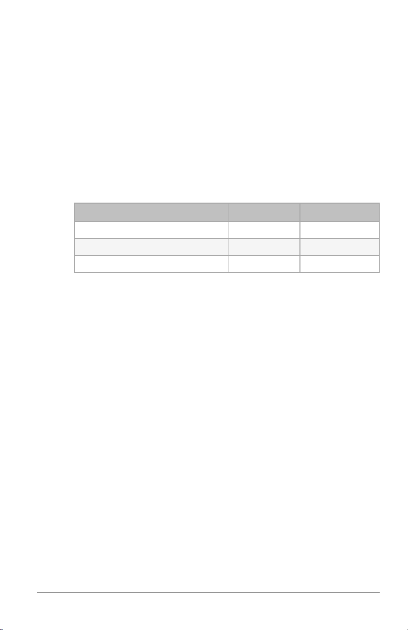
Typica l Power Consumption
Mode Power Cur r ent
Idle:DMXMode 1.2W .03A
Idle: ACMode 0W 0 A
Full Intensity 150W 1.26A
Environment
Ambi ent op erating temperatu re: 5°C–5 0 °C (41°F–122°F)
Mi nimu m storag e temperature: 5°C (41 °F)
Maximu m reco mmend ed ambien t operating temperature:Ta=5 0°C
(122 °F)
Maximu m anticipated external surface temperature: Tmax=63°C
(145 °F) at Ta=5 0°C (122°F)
External Temperature (stead y state achieved) at 25 °C (77°F)
ambi ent: 38°C (100°F)
Weight
Source 4 WR DII LED retrofit kit only: 1 .6 9kg (3.73lb)
Source 4 WR DII LED in stalled on 26° fixture with yoke and C-clamp:
6.39 kg (14.08lb)
Optical
Comp atible with all ETCSource Four l ens tu bes.
Source 4 WR D II I nstallatio n and User Man ual 5
Page 10

Retrofit the Fixture
Source 4WRD
LED Retrofit Kit
LEDs
RJ45 data in
and data thru
User interface and
navigation buttons
•
•
•
WARNING: RISK OF FIRE OR ELECTRIC SHOCK! Installing the
Source 4WRDII LED retrofit kit requires knowledge of
luminaire electrical systems. If you are not qualified, do not
attempt installation. Contact a qualified electrician.
AVERTISSEMENT : RISQUE D'INCENDIE OU DE DÉCHARGE
ÉLECTRIQUE! Installer le nécessaire de conversion Source
4WRDII LED nécessite une connaissance des systèmes
électriques de projecteurs. Si vous n’êtes pas qualifié, ne
tentez pas l’installation. Faire appel à un électricien qualifié.
Note:
LUMINAIRE WHERE THE SUITABILITY OF THE COMBI NATION SHALL
BE DETER M INED BY AUTHORI TIES HAVI NG JURISDICTION.
THE RETR O FI T KI T I S ACCEPTABLE AS A COMPONENT OF A
Wire the power connector(if needed)
If you ordered a Source 4 WR D II retro fit without a po wer connector, wire
the connector i n acco rdance with all n ati onal and l ocal el ectrical codes:
Brown = Live
Bl ue = Neutral
Green/Yel l ow = Pro tective earth
6 Source 4 WR D II I nstallatio n and User Man ual
Page 11

Remove Incandescent Lamp Housing
1. Unplug the Sou rce Four in candescent fixtu re and p lace it on a flat,
stab le surface.
2. Loos en the b rass thumb s crew located above th e beam adj ustmen t
knob. The lamp ho u sing is now lo ose.
3. Remo ve the lamp hou s ing from the fixtu re bo d y.
Note:
ETC to recycle th e b urner ass embly, contact ETC Technical Servi ces
for mo re information. See Hel p from ETC Technical Services on
page2 .
The burner assembly i s no long er needed. If you would l ike
Source 4 WR D II I nstallatio n and User Man ual 7
Page 12

Install the Source 4WRD II Retrofit
•
•
WARNING: RISK OF FIRE OR ELECTRIC SHOCK! Install this kit
only onto luminaires that have the construction features and
dimensions shown in the images in this document and where
the input rating of the retrofit kit does not exceed the input
rating of the luminaire.
AVERTISSEMENT : RISQUE D'INCENDIE OU DE DÉCHARGE
ÉLECTRIQUE! N’installer ce kit que sur les projecteurs qui ont
les caractéristiques de construction et les dimensions
indiquées sur les images de ce document et où la puissance
électrique nécessaire à la conversion n’excède pas la puissance
maximale du projecteur.
WARNING: Do not make or alter any open holes in an
enclosure of wiring or electrical components during kit
installation.
CAUTION:
anything other than oil-free canned air.
Tools required :
Adjustab le wrench
#2 Phillip s screwdriver
1. Use oil-free canned air to clean th e LED domes before you i nstall
the retrofit. Do not touch the LEDdomes.
Do not touch or clean LED optic domes with
8 Source 4 WR D II I nstallatio n and User Man ual
Page 13

2. With the fixture resti ng s ecurely on a flat surface, attach th e
Insert threaded
post here
Tighten
screw
Z-adjustment
knob
Source Four
fixture body
Lamp
housing
hole
su pplied threaded post to the back end of the fi xture body. Use an
adjustab le wrench to tighten the th readed p o st one-qu arter turn
past finger tigh t.
3. Gently sli de the Source 4WRDII LED o nto th e fixture bo dy and
thread ed post whil e guidin g the LED tower i n to th e l amp h o using
ho le, as shown bel ow. Take care to prevent con tact b etween the
LEDs an d the refl ecto r.
4. Use a #2 Phi llips screwdri ver to tighten th e s crew located on the
back en d of the Source 4WRDII LED, directly above the
Z-adjustment knob.
5. Pull gen tly to verify secure attachment.
6. Set the Z-ad justment using the Z-ad j ustmen t kno b . See
adjustment on page15
.
Set the Z-
Source 4 WR D II I nstallatio n and User Man ual 9
Page 14

Install the Fixture
Source 4WRD
LED retrofit
Source Four lens tube
(not included)
Adjustable yoke
Shutters (x4) Attached power lead
Cat5 cable
strain relief
Yoke locking knob
Attach C-clamp and Safety Cable
The C-clamp attaches th e fixture to the mounting pipe and allows you to
adjust the pos itio n of the mounted fixture. ETC recommends using 1.5in
schedule 4 0 pi pe.
1. Tightly fasten the C-clamp to the yoke with the pro vi ded yoke bolt
and lock wash er.
2. Place the C-clamp on moun ting pip e, and then tigh ten the pipe
bo lt to secu re it.
3. Loos en the C-cl amp pan screw an d rotate the yoke to th e desi red
po siti on.
4. Tighten th e pan screw to l ock the fixtu re.
5. Connect the s afety cabl e.
6. Tighten th e C-cl amp p i pe bolt to 1 5–20 ft-lb (20 –27 Nm),
approximately finger ti g ht plus up to one-qu arter turn.
CAUTION:
Do not exceed 25 ft-lb (33 Nm) while tightening
the C-clamp pipe bolt. Do not use excessive force.
7. Tighten th e yo ke pivo t b olt to 5–10 ft-lb (6–7 Nm), approximately
finger tig ht plus up to one-eighth turn .
10 Source 4WRD II Installati on and User Manual
CAUTION:
the yoke pivot bolt. Do not use excessive force.
Do not exceed 15 ft-lb (20 Nm) while tightening
Page 15

Connect Cables
•
•
You can control the fixture u sing AC po wer or DMX. Confi gure the fixture
to u se the appropriate control metho d on the user interface. See
Configure the Fixture on page14
WARNING: Do not use or store the Source 4WRD II fixture
below 5°C (41°F). When the fixture has been stored or
transported in cold temperatures, allow it to warm to room
temperature for a minimum of 1 hour before applying power.
Applying power to a cold fixture will cause damage to the
fixture and void ETC warranty.
.
Note:
For op timum performance, make sure that your dimmer is
ou t o f reg ulated mo de. See Li n e-dimming on the next p age for
recommended dimmer setti ngs.
Note:
Connecting both po wer an d data from a SmartBar 1 to a
Source 4 WR D I I fixture may caus e flickering.
1. If you are us i ng DMX co n trol: Connect one RJ45 data cable for
data-i n and one fo r data-th ru, as needed. Use the s train relief at
the bottom o f the fixture to su p port the data cables.
To o rder an RJ45-to-female XLR adap ter, u se ETC part number
W653 8.
To o rder an RJ45-to-male XLR adap ter, u se ETC part number
W653 9.
2. If you are us i ng DMXcontrol an d this is the last fi xture in the li n e,
termin ate the fixtu re with a 12 0Ohm resistor. Pl ease contact your
ETC cus tomer service repres entative to purchas e ETC part number
N4086. See
3. Connect the fixtu re to the power source.
Help from ETC Technical Services on page2
.
Source 4 WR D II I nstallatio n and User Man ual 11
Page 16

DMXDimming
•
•
•
•
•
•
When d imming via DMX, consider th e foll o wi ng:
When u sing DMX over Cat5, u se Cat5e o r better.
Cabl e distance must not exceed 30 0 m (100 0 ft).
Up to 32 fixtu res can b e co nnected to gether i nto a daisy chain.
The So urce 4WRD I I fixture cann ot be controll ed via Ethernet
protocols and shou l d n o t be directl y connected to an Ethernet
system.
When DMX d ata is l ost, th e LEDemitters turn off.
The fi xture uses a si n gle DM Xchannel for inten sity control.
DMXpinout
Pin Descript ion
1 DMX +
2 DMX -
3 Not connected
4 Not connected
Pin Descript ion
5 Not connected
6 Not connected
7 Commo n (shield)
8 Not connected
Line-dimming
When l ine-dimmin g the fi xture, s et the parameters as shown in the
followin g tabl es to en sure that the di mmer is out of reg ulated mode.
(You may need to adjust d immer settings for optimal fixtu re contro l ).
In addition to the recommended s etting s in the fo l lowing tables, you may
need to i n crease the SCR Off Time fro m the default setting. Con tact ETC
for as sistance in chan ging the SCR Off Time, or an y other CEM classic,
CEM+, or CEM3 settin gs. See
For the mo st curren t i nfo rmati on o n additional d immer performance
testing fo r both ETC and n on-ETC d immers, p l ease visit the ETC webs ite:
http s://s upport.etcconnect.com/ETC/Fixtures /Source_Four/Source_
4WRD%2 F%2FSource_4WRD_PAR /Dimmer_Settings_fo r_Use_with_
Source_4 WR D
Help from ETC Technical Services on page2
.
12 Source 4WRD II Installati on and User Manual
Page 17

Note:
When l i ne-dimming the fixtu re, perfo rmance may vary
based on th e con trol settings of th e d immer. For th is reason, ETC
recommends using line-dimmi n g for level-s etting or fo r
architectural d imming. ETC recommends testin g the Sou rce 4WRD
II fi xture on all existing d immers that you want to u se.
Use DM X mod e wh en h igh-performance, live, dynamic dimmi n g is
requ ired.
CEM + and CEM 3
Paramet er CEM+ CEM3
Cur v e Mod Square Mod Square
Thr eshold 1% 1%
Min Scale 6V 1%
Max Scale 140V 100%
Regulat ion OF F OFF
Preheat Disabled Disabled
DC Prevent OF F OFF
Inr ushPrevent O FF OFF
Scale Load 100 100
CEM Classic v2. x
Paramet er Value
Mode Nor mal
Boost 117
CEM Classic v3. x
Paramet er Value
Mode Nor mal
Cur v e Mod- Sq uare
Scale 140
Thr eshold Nor mal
Source 4 WR D II I nstallatio n and User Man ual 13
Page 18

Configure the Fixture
•
•
•
Up and down
navigation buttons
User interface
The two -butto n , seven-seg ment displ ay s h ows the DMXaddress ,
ACmode, or the manually-set level. Use the up and down navi g ation
bu ttons to confi gure the fixture.
Set a DM X addres s: Use the up and down arro ws to navigate to the
desired DM X ad dress numb er (1–512).
Set the fi xt u re to use l i n e-dimmin g (ACmode): Use the down
arrow to n avigate o n e numb er below DMX addres s 1. The d isplay
will read A C.
Man u ally s et a level : Use the down arro w to navigate one nu mber
below AC. Th e display wil l read L .F L (Level = Ful l). Us ethe down
arrow to d ecrease the l evel to a p ercentage of full (L.99 = 9 9%,
L.98 = 98%, etc.). You can set levels fro m 0%–100% (full).
RDMValues
Parameter RDMPI D Value
Manufacturer ID 0x6574 Electro n ic Theatre Co ntrols
Mo del ID 0x08 00 ETC So urce 4WRD I I (120 V)
DMX Start Address 0x00 F0 Rang e = 1–5 12
1 = DMX
Personality ID 0x00 E0
14 Source 4WRD II Installati on and User Manual
2 = ACDimming
3 = Local Control
Page 19

Focus the Fixture
Ideal beam of
uniform light
Adjust toward PEAK to
blend overlapped beams
Adjust toward FLAT to
improve sharp focus
Z-adjustment knob
Set the Z-adjustment
Use th e Z-adj u stment knob located on the rear o f the fixture to adjust the
fiel d of the LED l ight for speci fic app l ications.
1. Turn on th e fixture and aim i t at a fl at su rface.
2. Slide the fi xture barrel toward or away from the So urce 4WRDII LED
to create a h ard-edged beam o f light.
3. Turn the kn o b toward PEAK o r FLAT until yo u achieve the desired
fiel d.
Source 4 WR D II I nstallatio n and User Man ual 15
Note:
for PEAKfocus. When us i ng the So urce 4WRDI I LED i n a Source
4WRD PAR or PARNel Fixture Body, turn th e Z-adjustment kn ob
toward PEAK until the knob b ecomes loose, an d then ti ghten the
Z-adjustment kn o b an additional qu arter turn. Th is sets the LED
li ght source i nto the appropri ate p ositi on within the Source 4WRD
PAR or PARNel fixture.
The So u rce 4WRD II PAR and PAR Nel optics are o ptimized
Page 20

Adjust the Yoke Position
Low clearance
position
General use
position
Yoke locking
knob
Change the Height Position
1. Remo ve the yoke locki ng knobs ,
washers, and hex bolts fro m either s ide
of the fixture.
2. Raise or l ower the fixture to the d esired
po siti on within th e yo ke.
3. Reinstal l the yoke’s h ex bolts , was hers,
and lockin g knobs.
4. Tighten th e yo ke knobs to secu re the yoke i n po s iti o n.
Set the Angle within the Yoke
1. Loos en the yo ke locking knob . Do n o t
remove th e knob .
2. Tilt the fixture to the desired posi tion .
3. Tighten th e yo ke locking kno b to s ecure
in pos itio n.
16 Source 4WRD II Installati on and User Manual
Page 21

Shape the Beam
Retaining
clip
7.93 cm
(3.12 in)
diameter
7 cm
(2.75 in)
diameter
9.4 cm
(3.7 in)
9.4 cm
(3.7 in)
A-size pattern holder:
Holds 7.6 cm (3 in)
diameter patterns
B-size pattern holder:
Holds 6.35 cm (2.5 in)
and 7 cm (2.75 in)
diameter patterns
You can shape the beam by u sing the s h utters, a p attern, an optional
drop-in iris , an d by rotating th e barrel.
Use the Accessory Holder
The accessory hol d er is equipped wi th a spri ng-l oaded retaining clip that
prevents colo r frames and accessories from fal l ing out.
WARNING: Make sure all color frame accessories are locked
in position with the retaining clip before hanging the fixture.
AVERTISSEMENT : S’assurer que tous les porte-filtres sont
verrouillés en place à l’aide du verrouillage de la cassette
avant de suspendre le projecteur.
1. Release the retainin g cli p by pushi n g it
si deways whil e gently p ulling backwards.
2. In sert the col or frame or accessory.
3. Lock the retainin g clip by pushin g
si deways whil e gently p ushing fo rward.
Use a Pattern
The pattern h o lder s lot is on the top s ide of the barrel and in front of the
sh utters. It accommodates A-s ize, B -size, and g lass pattern h olders.
Becau s e the Source 4 WRD II fixture apertu re is 3 inches wide, ETC
recommends A-size patterns for maximum effecti venes s.
Source 4 WR D II I nstallatio n and User Man ual 17
Page 22

Troubleshoot the Source 4WRD II
•
-
-
•
•
•
-
-
-
The fo llowing erro r co des may b e s een o n the So u rce 4WRD II user
in terface. For mo re troub lesh ooti n g assistan ce, s ee
Techni cal Services on page2
.
OtP (OTP) indicates that the fixture has go ne into over-temp erature
protecti on. Allow the fixtu re to cool , an d then reset th e fixture to
clear the code.
For DMX mode: R eturn the DMX control to 0.
For AC mode: Remo ve the fixture from power for five seco nds
and then res tore power.
UtP (UTP) ind i cates that th e fixture has gone into under-
temperature pro tection. All ow the fixture to warm to a min i mum o f
5°C (41°F).
Flashing D M X addres s indi cates loss of DM X.
Dark screen indi cates loss of power or fixture time-out. In the event
of time-out, press any button to wake the user interface. If this fails
to wake the user interface, tro ubleshoot the power loss:
Verify that all cables are full y seated and that po wer is app lied to
the fi xture.
If a wo rki ng Source 4WRDII LED i s avail able, exch ange the Source
4WRDII LED with the working So urce 4WRDII LED to further
is olate an y issu es.
If the fixture sti ll d oes not resp ond, con tact ETC Tech nical
Services fo r addi tional troubleshooting steps or to arrang e a
repair. See
contact i n formati o n.
Help from ETC Technical Services on page2
Help from ETC
for
18 Source 4WRD II Installati on and User Manual
Page 23

Clean and Maintain the Fixture
Fan and
fin stack
•
•
Store with
LED dome up
•
•
•
Clean the Fixture
CAUTION:
anything other than oil-free canned air.
Use oil-free canned air to clean th e LED
do mes prior to i nstallatio n and prio r to
storage.
Use oil-free canned air to clean th e fan
and fin stack as part o f regular fixture
main tenance.
Do not touch or clean LED optic domes with
Store the Retrofit
When n ot install ed on a fixture, store the
Source 4 WR DII LED in its o rigi n al packag ing o r
in a dus t-resistant pl astic bag.
Store th e Sou rce 4WRDI I LED at temperatures
of 5 °C (41°F) or higher.
If you must store the So urce 4WRDII LED below
5°C (41°F), make sure it is in an upri ght
po siti on as s hown to the right. Allow it to
warm to room temperature for a minimum of
on e hour before ap plying power.
Note:
5°C (4 1°F), visually i n spect the unit to ensure the low
temperatures have not caused cracking of the LED array.
Source 4 WR D II I nstallatio n and User Man ual 19
After sh i pping or sto ring th e Source 4 WR DII LED below
Page 24

Clean the Lenses
WARNING: Do not use ammonia-based or other harsh
commercial cleaners. Clean lens and reflector only as directed.
Commercially available glass cleaning agents should be
avoided as they may contain ammonia, other harsh chemical
detergents or abrasive agents. These cleaners may damage
the glass surface and the Anti-Reflective coatings. Do not
immerse or soak the glass in any cleaning solution.
Note:
from the len s tube. For instructions on removing the lenses, see
the So u rce Four As sembly Gu i de, wh ich is availab le for do wn l oad
at etcco nnect.co m.
Replace lens es if th ey co n tain vi s ible damage (cracks or deep scratches)
that may imp air thei r effectiveness .
1. Remo ve the lens tube fro m the fixtu re barrel:
2. Remo ve any d ust with a bl ast of o i l-free ai r or wipe with a clean,
3. Slide the lens tube back into the barrel with the color frame
To clean th e i nside of lenses , you must remove the lenses
a. Remove th e b eam focus knob and retainer bolt from the top
of the barrel an d set as ide.
b. Slide the lens tube ou t of the b arrel.
li nt-free cloth. Yo u can us e isopropyl alcoho l, dis till ed water, or a
50 %-50% mi xture of each to cl ean the glass surface.
retai n ing cl ip o n top. R eins tall the beam focus knob and retai ner
bo lt.
20 Source 4WRD II Installati on and User Manual
Page 25

Clean the Reflector
WARNING: Unplug the fixture and allow it to cool before you
clean the reflector.
AVERTISSEMENT : Débrancher le projecteur et le laisser
refroidir avant de nettoyer le réflecteur.
To q uickly clean the reflector, remove the lens tube and cl ean the dust
from the reflector with a blast of oi l -free air. You may also wipe th e
reflector with a clean lint-free cloth. If eith er method is n ot sufficient,
follow these steps .
1. To p rotect the lamp housin g du ring cleanin g, remove the LED lamp
ho using by l o osen ing the attachmen t screw an d pu lling th e
ho using straight out. (See image o n
2. Remo ve the barrel rotatio n knob located at the b o ttom of th e
barrel . Us e a Phi l lips screwdri ver to remove the retai n er bo l t located
on top o f the reflector hou s ing.
3. Ro tate the barrel 45° in either d irection . Carefu lly remove th e
barrel from the reflector housi n g.
4. Remo ve any d ust with a bl ast of o i l-free ai r or wipe with a clean,
li nt-free cloth. Yo u can us e isopropyl alcoho l, dis till ed water, or a
50 %-50% mi xture of each to cl ean the glass surface.
5. In sert the b arrel in to the reflector ho u sing with th e iris /p attern slot
on top. Align th e triang les on both parts.
6. Whil e gently p ressing in, rotate the b arrel 45 ° clo ckwise un til it
sets into position, and th en rotate th e barrel cou nterclo ckwise 45° .
The barrel shoul d be firmly attach ed an d the triangles sh ould be
aligned.
7. Reinstal l the barrel rotation kn ob and tig hten the retainer bolt.
8. Reinstal l the LED l amp ho u sing and tighten the attach ment screw.
See
In stall the So urce 4WRD II Retro fit on pag e8
page9
.)
.
Source 4 WR D II I nstallatio n and User Man ual 21
Page 26

Clean 5° and 10° Polymer Lenses
To q uickly clean the lenses, remove dust with a b last o f oil-free air. If thi s
is not s ufficien t, follo w th ese step s.
CAUTION:
rub anything dry on a polymer lens.
1. Remo ve the beam focus kno b at the b ottom of the barrel. R emove
the lens tube from the barrel.
2. Use a Ph illips screwdriver to remove th e brackets th at hol d the len s
in place. Remove th e lens from the tu be.
3. Dip the lens in a cl ean is opro pyl alcohol/water mixture (9 parts
water to 1 p art isopropyl alcoh o l).
4. Use a soft moi stened nylo n bristle bru sh to wash the s mooth side
of the lens in a l i near (non-circular) mo tion.
5. Use th e same bru sh to lightly wash the ridged si de of th e lens by
followin g its ridg es.
6. Dip the lens in a cl ean is opro pyl alcohol/water mixture (9 parts
water to 1 p art isopropyl alcoh o l).
7. Dry the s mooth and rid ged surfaces with an air gun. Make sure
that the air flo w mo ves liquid away fro m yo u.
8. In spect the lens for dirt. Rep eat steps 3–7 if necessary.
9. Set the lens b ack in the l ens tu be with th e ridg ed side facing the
fron t of the tube. Reinstall the len s brackets.
10 . Slide the lens tube b ack into the barrel with the retaining clip for
the color frame o n top. R eins tal l the beam focus knob .
Handle polymer lenses by their edges only. Never
22 Source 4WRD II Installati on and User Manual
Page 27

Source 4 WR D II I nstallatio n and User Man ual 23
Page 28

Corporate H e a dqu a rters Middleton, WI, USA +1 608 831 4116
London , UK +44 (0) 20 8896 1000 Ho lzk irc he n, DE +49 ( 80 24) 47 00-0
Rome , IT +39 (06) 32 111 683 H ong Ko ng +852 2799 1220 Pa ris, FR + 33 1 4243 3535
We b etc connect.c om Supp or t support.etc connect.com
Contact etc c on nec t.c om/contactETC © 2020 Electronic Theatre Controls, Inc .
Produ ct in formation and sp ecifications su bjec t to ch ange. ETCintends this doc umen t
to be provided in its entirety. Trademark and patent info :etc connect.c om/ip
7067 M12 3 0 -1 .1 .2 Rev A R eleased 2020-02
 Loading...