

Page 1
ETC Setup Guide
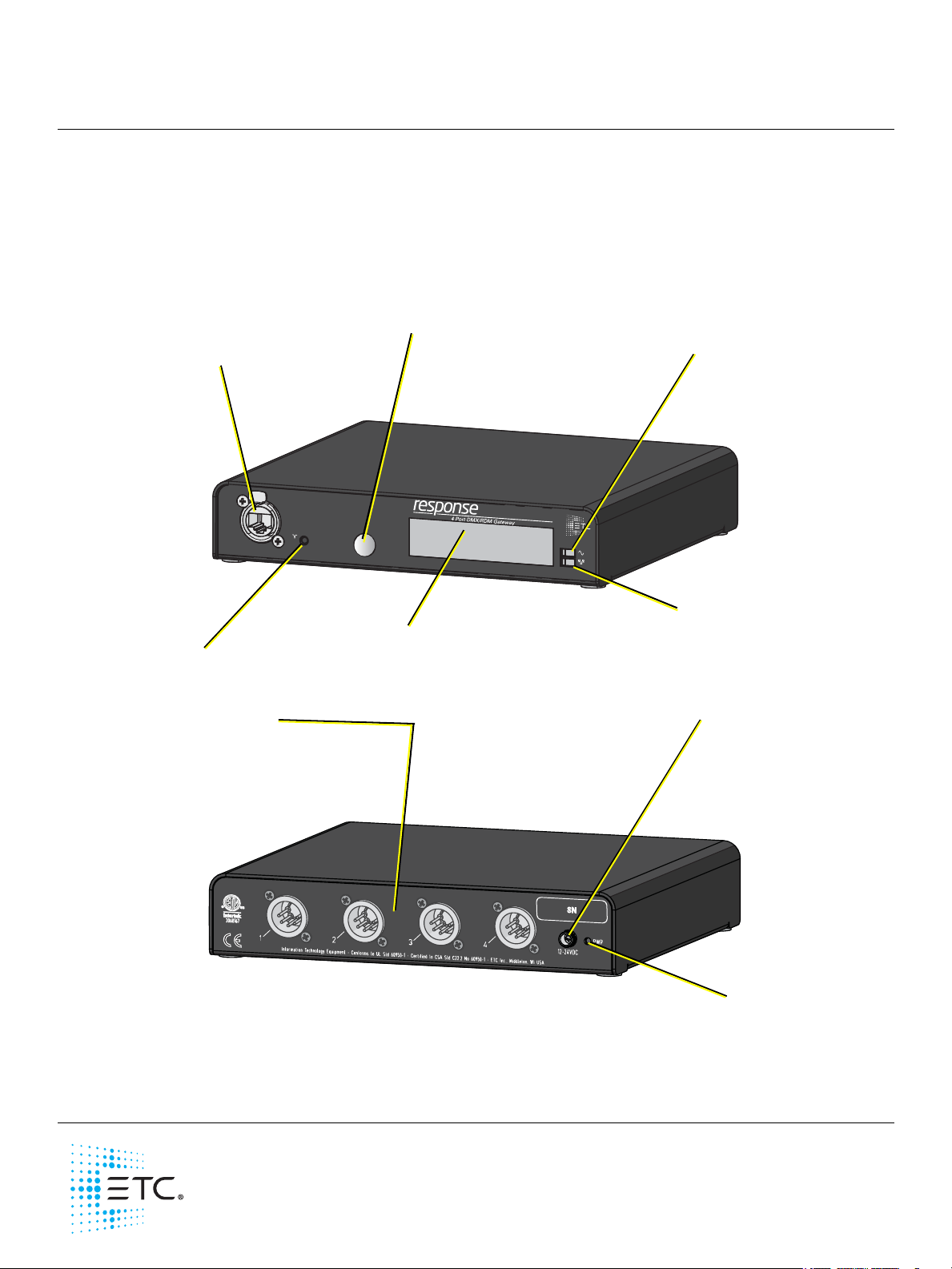
Ethernet Connection
• PoE (IEEE 802.3af)
• 10/100Mbps data
speeds
• Auto-sensing
• Auto-negotiation
• RJ45 and etherCON
compatible
Reset Button
Performs hard reboot
Menu Button
• Activates the LCD backlight
• Advances display pages
LCD
Displays gateway status and
configuration data
Power Indicator
Solid blue LED indicates
power
Activity Indicator
• Solid green LED indicates
network connection
• Flashing LED indicates
network activity
Available configurations:
• 4-DXM Out (XLR Female)
• 4-DMX In (XLR Male)
•1-DMX In 3-DMX Out
• 4-DMX Terminal
•4-DMX RJ45
DC Power Input
• 8-28VDC
• Positive tip
• 3.5mm barrel
•5 Watts usage
Power Indicator
Solid blue LED
indicates power
Response Four-Port DMX/RDM Gateway
Overview
This Setup Guide will guide you through the setup of the Response Four-Port DMX/RDM Gateway (version
7.x software and later) including hardware, electrical and data connections. Software configuration of your
gateway is covered separately and relates specifically to the software versions that may be running in the
gateways.
For configuration, refer to the Net3 Concert Online Help System.
Corporate Headquarters Middleton, WI, USA Tel +608 831 4116 Service: (Americas) service@etcconnect.com
London, UK
Rome, IT
Holzkirchen, DE
Hong Kong
Web: etcconnect.com
Product information and specifications subject to change. ETC intends this document to be provided in its entirety.
4267M2230
Tel +44 (0)20 8896 1000 Service: (UK) service@etceurope.com
Tel +39 (06) 32 111 683 Service: (UK) service@etceurope.com
Tel +49 (80 24) 47 00-0 Service: (DE) techserv-hoki@etcconnect.com
Tel +852 2799 1220 Service: (Asia) service@etcasia.com
© 2016 Electronic Theatre Controls, Inc.
Rev A Released 2016-12
Page 2
ETC Setup Guide
1
2
3
4
5
Push
1
2
3
4
5
Push
18
18
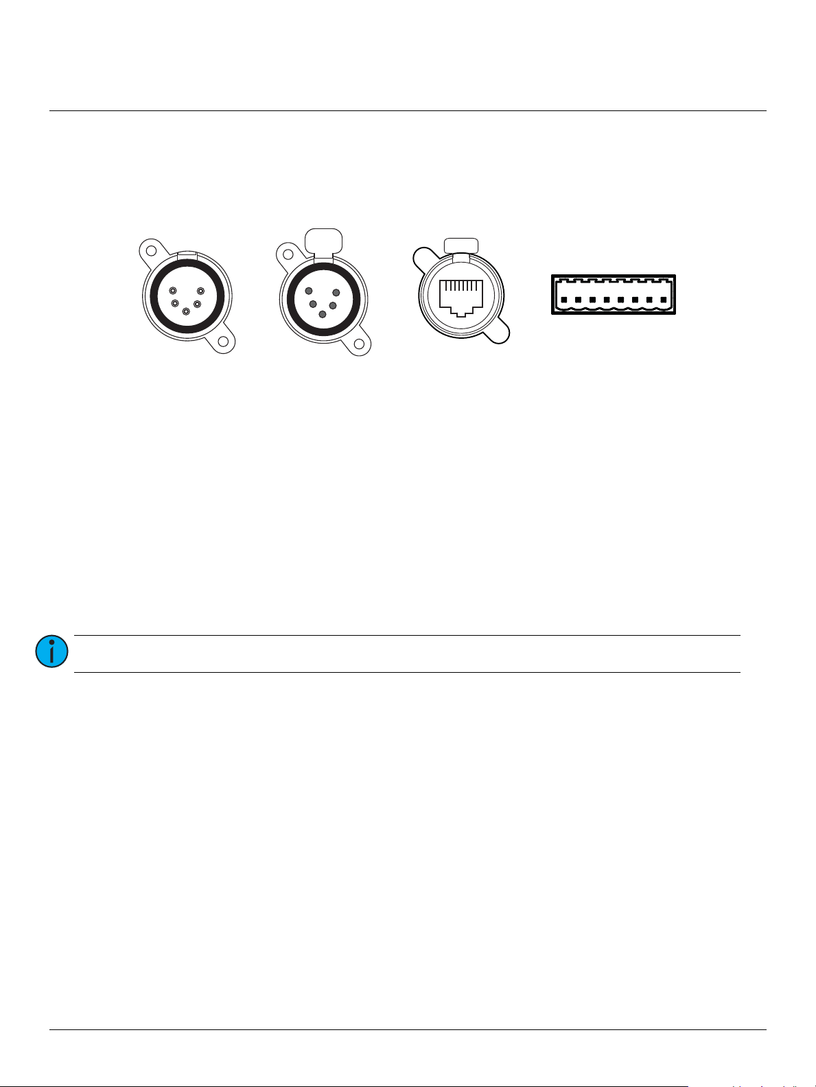
DMX In
(XLR 5-pin male)
DMX Out
(XLR 5-pin female)
DMX RJ45
(RJ45 female)
Terminal Strip
(8-pin male)
Four-Port DMX/RDM Gateway
Gateway Connection Options
There are four different connection options available for use in the Four-Port gateway: DMX Out (5-pin
female), DMX In (5-pin male), DMX RJ45 (input or output) or DMX Terminal Strip (8-pin terminal for input
or output).
The terminal strip variant comes with ETC’s standard DMX termination preparation kit (part number
4100A012) which includes instructions and all parts required for installation. If you are connecting to
Category 5 wire for DMX, request the DMX termination preparation kit with IDC connectors from ETC (part
number 4100A1013).
The DMX RJ45 variant can use a standard Cat 5 cable to transmit DMX512 to other devices utilizing the
same connector.
This gateway is available in five configuration options:
• Four DMX Out Ports
•Four DMX In Ports
• Four DMX RJ45 Ports
• Four DMX Terminal Strip Ports
• Three DMX In Ports and One DMX Out Port
Note:
The DMX RJ45 port does not function as an Ethernet network port.
Four-Port DMX/RDM Gateway Setup Guide Page 2 of 5 ETC
Page 3

ETC Setup Guide
DMX 512 Pinout for 5-pin XLR Connectors
Female
(output)
Pin# Use
Male
(input)
1 Common (shield)
2 Data -
3 Data +
4 not connected
5 not connected
Push
1
2
3
4
5
1
2
3
4
5
DMX512 Pinout for RJ45 Connectors
Female Pin# Use Wire Color
1 Data 1 + White/Orange
2 Data 1 - Orange
3 not used White/Green
4 not used Blue
5 not used White/Blue
6 not used Green
7 Signal Common White/Brown
8 Signal Common Brown
DMX512 Pinout for Terminal Strip Connector
Female Pin# Use Wire Color
1 Common (shield) Clear/Shield
2 Data - Black
3 Data + Red
4 unused
5 unused
6 unused
7 unused
8 unused
18
Four-Port DMX/RDM Gateway
Basics and Pin-Outs
The Response Four-Port DMX/RDM Gateway sends and receives DMX512 control signals. This unit contains
four DMX ports in one of the configuration options listed in the
DMX cables must be acceptable for DMX data transmission (not microphone cable) and connections
should follow the standard pinouts per the charts below. The optional secondary data pair is not used by
the Four-Port gateway.
Gateway Connection Options
Push
18
section.
Four-Port DMX/RDM Gateway Setup Guide Page 3 of 5 ETC
DMX Termination
The DMX network supports up to 32 devices connected to each DMX line. Termination is required for all
DMX networks and belongs at the source (beginning) of a DMX network line and at the last device
physically connected in the line. A termination switch is located internally for each input/output and can be
configured for DMX termination (IN), No termination (OFF) or RDM termination (OUT). By default, the DMX
termination switch is set to the RDM termination (OUT) position. If you need to change the termination
setting, contact ETC technical services.
Page 4

ETC Setup Guide
The front panel connector bracket replaces
the rack mount kit blanking plate.
Four-Port DMX/RDM Gateway
RDM Basics
The software supports Remote Device Management (RDM) protocol. By default, RDM discovery is not
enabled on the Four-Port gateway. To enable RDM on the gateway, use ETC’s Net3 Concert software.
Please see the Concert online help files for more information on activating RDM on your gateways. You can
also press and hold the Menu button on the “Discovery Off #0” menu item for the desired port.
About RDM
Remote Device Management (RDM) is a protocol enhancement to DMX512 that allows bidirectional
communication between a lighting system controller and attached RDM-compliant responder devices over
a standard DMX line. This protocol allows configuration, status monitoring, and management of these
devices.
An RDM Controller is the device that initiates communication with one or more RDM Responder devices.
Examples of responders are RDM-enabled edge devices such as color scrollers, dimmers, moving lights, and
LED fixtures. RDM supports 32 RDM devices per-port, just like DMX. Compliant DMX512 and DMX512-A
devices (non-RDM devices) are fully functional when RDM is present. RDM was developed by ESTA
Technical Standards and can also be referenced as ANSI E1.20.
Optional Accessories
The following accessories are available for use with the four-port gateway.
Rack Mount Kit
4260K1001: The Gateway Rack Mount kit is capable of holding
up to two Four-Port gateways for mounting into a standard
19” rack enclosure. If you only need to mount one unit, a
blanking plate is provided with the kit. This blanking plate can
be installed on either side of the rack mount bracket.
Hanging Hardware Kit
4260K1005: The Hanging Hardware kit allows pipe mounting of a
gateway in a variety of orientations. You can vary the way the U-bolt
(or c-clamp) attaches to the bracket and the way the bracket mounts to
the gateway. The bracket attaches to any edge on the bottom of your
gateway.
DMX Front Panel Kits
4260K1002 - DMX out: This kit provides front panel access to the DMX connectors on a DMX/RDM FourPort Gateway when installed in an equipment rack. You must use these kits in combination with one
Response Four-Port DMX/RDM Gateway and a Rack Mount Kit (4260K1001), not included.
Four-Port DMX/RDM Gateway Setup Guide Page 4 of 5 ETC
Page 5

ETC Setup Guide
v7.0.x Menu
My DMX Gateway
999 ... X DD
Port 1 Output
sACN 3/4:511
Port 1 RDM Enabled
Discovery On #12
Port 2 Input Pri***
Custom (AIP)
Port 2 RDM Disable d
Port 3 Input Pri 100
sACN 2:512
Port 3 RDM Disable d
Port 4 Output
sACN 1
Port 4 RDM Enabled
Discovery Off #0
Static IP Address
10.101.50.107
IP Su bn et M as k
255.255.0.0
IP Ga tew ay
10.101.50.101
TFTP Server
10.101.50.43
ACN Gateway Version
7.0.0.9.0.X
Hold button 5 sec to
Reset Dynamic IP
Hold button 5 sec to
Download Software
Hold button 5 sec to
Restore Defaults
Mac Address
00:C 0:16:0 0:0 0:1A
• displays the por t priority mode (eit her “Outp ut”, “Input Pr i ***”, wher e *** indi cates the po rt is set wi th per-addre ss prior ity,
or “Input Pr i 100” (wher e 100 is the pr iority va lue for that po rt). Displ ays either “I nput” or “ Output ”.
• displays the patc h informat ion format ted as “unive rse”, “universe /address”, “univer se/addres s:length”, “univer se:length”
or “Custom (AIP)”.
• displays the por t RDM status (either “En abled” or “ Disable d”). Can be en abled or dis abled at the ga teway only
if the por t is set to “Out put” mod e by holding th e [Menu] button for 5 seconds.
• displays discove ry status (ei ther “Fast ”, “On”, or “Off ”).
• displays eithe r “Static ” or “Dyna mic” IP Addr ess.
• displays the cur rent IP address of the gateway.
• displays the cur rent Subnet Mask of the gateway.
• displays the cur rent IP address for a netw ork router (or t he gateway’s own I P address).
• displays the cur rent Trivial File Transfe r Protocol ( TFTP) server IP addre ss for the gate way. The TFTP ser ver is
typica lly an ETC cons ole or comp uter runnin g Gateway Conf iguratio n Editor (GCE) sof tware.
• displays the version number of the software currently running on this device.
• if the IP mode is s et to Static, “ Switch to D ynamic IP ” displays. I f the IP mode is D ynamic, “ Reset Dyna mic IP”
displays. Res etting th e Dynamic IP e rases the cu rrent IP fr om memor y and reques ts an IP from t he DHCP
address se rvice af ter reboot.
• software i s retrieved f rom the cur rent TFTP up date serve r .
• restoring def aults will c ause the gate way to reset all set tings to the factory d efaults.
• DMX universe n umbers up to 9 99 are disp layed on the fro nt panel. Uni verses that a re higher th an 999, or f lexibly patc hed
outputs, ar e indicate d by “...” (you must go to the por t screen to see full detai ls).
• The unit display s either the “g ateway name” or t he “IP Addre ss” as well as ea ch port an d its por t status.
• Port Status includes:
-- arrow direc ted toward t he number ind icates an inp ut (999)
-- arrow dire cted away from t he number in dicates an o utput (99 9)
-- an X indicate s the univers e port is di sabled, no un iverse numb er is shown (X )
-- a dimmer doub led port d isplays only “ DD” (you must go to the por t screen to see full detai ls)
-- when a por t is set to downl oad mode, “D NLD” disp lays.
-- AIP inputs a re indicate d as “AIP”
-- a port wil l blink on the di splay when it do es not have DMX c onnecte d (input) or has no val id source da ta (outputs).
Four-Port DMX/RDM Gateway
Power Up Using DC Power
When using an external power supply, the gateway must be connected to a network before being
powered. Using PoE and DC power simultaneously is not supported.
Menu Structure
The DMX/RDM Four-Port gateway has a single-button interface. Pressing the [Menu] button repeatedly
cycles through the menu, displaying mostly informational data. On certain menu items you are prompted
to press and hold the [Menu] button for a period of five seconds to change a state or switch between
operating modes. The menu structure is displayed below for your convenience.
Four-Port DMX/RDM Gateway Setup Guide Page 5 of 5 ETC
 Loading...