

Page 1
ETC Setup Guide
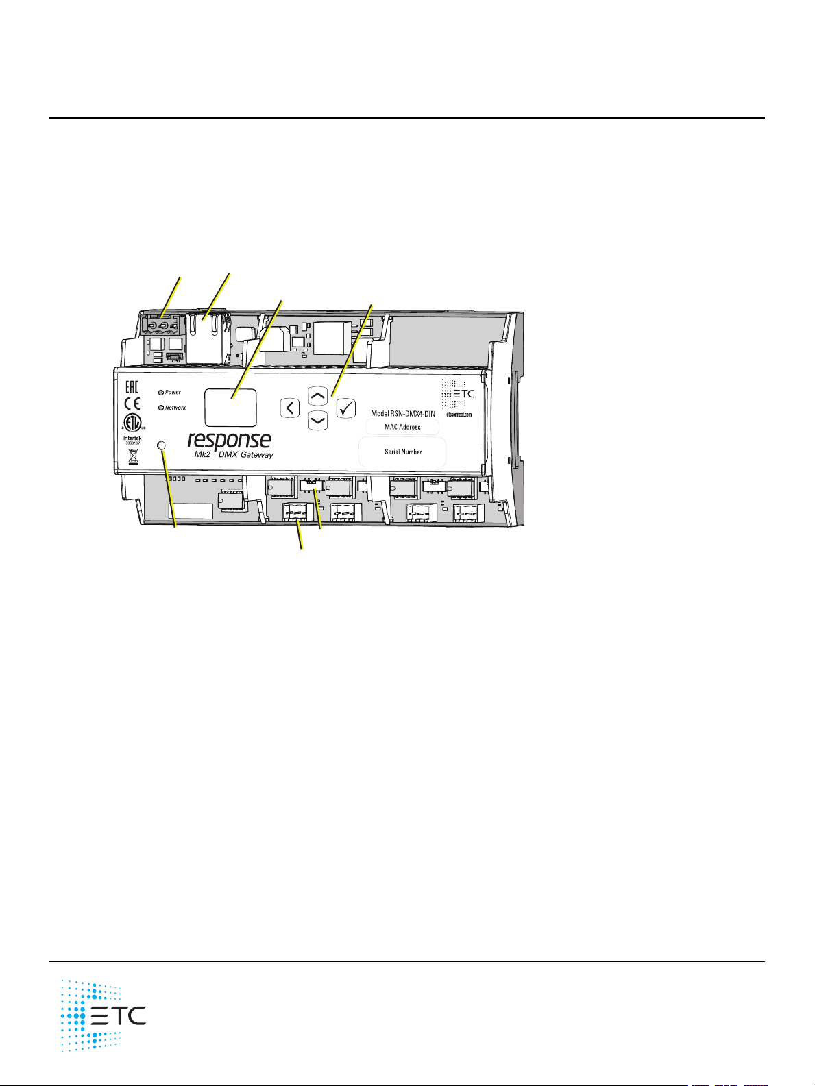
OLED screen
Up, Down, Back,
Enter buttons
DC power
input
Ethernet
connection
Three-pin terminals (Typical 1, 2, or 4)
DMX termination switches
Reset button
•
•
•
•
•
Response Mk2 DIN Rail Gateway
This guide covers installation and basic setup of the Re sponse Mk2 DIN Rail Gateway. You can
configure additional software features using ETCConcert software. Reference the Help system built
into Concert for more information. ETC Conce rt software can be found at etcconnect.com/Concert.
Overview
The DIN rail gateway come s with one , two, or four ports.
Action Buttons
Up, Down, Back buttons - T he Ba ck button allows you to return to the previous menu or option
and the Up and Down buttons navigate between menu options
Enter - The Enter button allows you to a dvance to the next available menu option or commit a
modified selection
Reset - The Reset button provides a physical button to reset the gateway
LED Indicators
Power - Solid blue indicates that power is supplied
Network - Solid green indicate s network connection and blinking indicates network activity
Corpora te Headqua rters Middleton, W I, USA +1 608 8 31 4 116 London, UK +44 ( 0) 20 8 89 6 10 00
Holzk irchen, DE +49 (8 0 24 ) 47 0 0- 0 Rom e, IT +3 9 (0 6) 3 2 11 1 683 Hong Kong +852 2799 1220 Pa ris, FR +33 1 42 43 353 5
We b etcconne ct.com Support support.etc conne ct.com Contac t e tcc onnec t.com /conta ctE TC
© 2 02 0 Ele ctronic Thea tre Controls, Inc. Tradem ark and pa tent info:etcc onnec t.com /ip
Product information a nd spe cific ations subject to c hange . E TCintends this doc ument to be provided in its e ntirety.
42 68M22 30 Rev C Released 2 020-08
Page 2
ETC Setup Guide
•
•
1 3
DIN Rail Gateway
Electrical Specifications
The gateways are powered by either auxiliary power or P ower over Ethe rnet (P oE).
Auxiliary power input rated voltage of 12-24 VDC, 6.49 W Max
10/100Base-T, PoE power Cla ss 2 (IEEE 802.3af)
For auxiliary power, the DIN rail gateway uses a three-position screw clamp termina l block.
If you supply both PoE and auxiliary power, the gateway defaults to using auxiliary. If auxiliary
power is lost, the gateway will reboot and then begin using PoE.
Note: If you are using an e xternal power supply, it must be rated at a maximum of
15watts.
DMXConnection
The Response Mk2 Gateways send and receive DMX-512 control signals. DMX cables must be
acceptable for DMX data transmission and conne ctions should follow the standard pinouts per the
chart below.
The DIN rail gateway come s with one , two, or four te rmina l connectors.
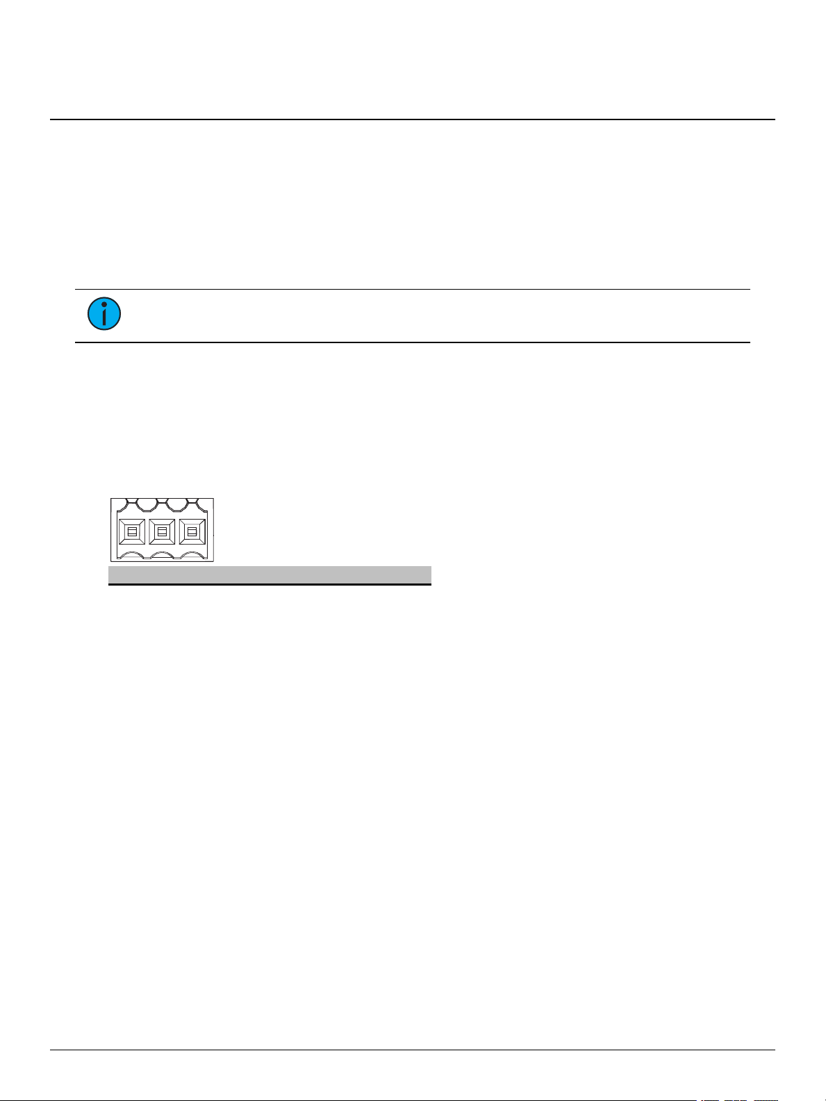
Pinout
DM X-512 Pinouts for Terminal Heade r
Pin Use Typica l Wire Color
1 Common (shield) clear/shield
2 Data - black
3 Data + red
DIN Rail Gateway Page 2 of 8 ETC
Page 3
ETC Setup Guide
•
•
D1
12
10
11
12
8
5
5
6
7
3
+-
com
DIN Rail Gateway
Wiring the Terminal Connector
The terminal header can acce pt two types of connectors (both connector types are provided with the
gateway):
DMXCable (three-position screw connector used with Belden 9729 or equivalent cable)
DMXCat5 (three-position Cat5 insulation displacement connector used with Cat5 or
equivalent cable)
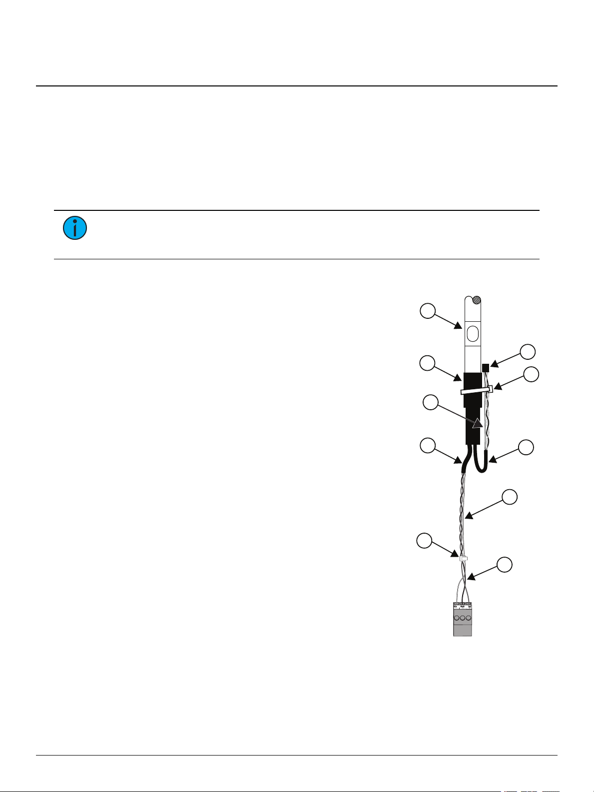
DMXCable Preparation and Termination
Note: Not for use with Cat5, Cat5e, or Cat6 cable. W he n running DMXwith these cable
types, use the provided 3-position IDCconnector and reference DMXCat5 Pre pa ra tion and
Te rmination on the next page.
This instruction assumes preparation of Be lden 9729 (or equiva lent) cable for termination to the
three-position screw terminal connector provided.
1. Install the cable so there is an 20 cm (8 in) service
loop available at the rear of the gateway.
2. Strip 18 cm (7 in) off the outer jacket.
3. Label the ca ble with the data type and run
designation. (DMX1, DMX2, etc.)
4. Strip the foil shielding from each wire set to within
6 mm (1/4 in) of the outer jacket.
5. Untwist the shield wire from each pair and apply a
piece of 1.6 mm (1/16 in) clear heat shrink to e ach
shield wire.
6. Twist each shield wire back onto its data pair, and
then apply a 4 cm (1. 5 in) piece of 0.5 cm (3/16 in)
heat shrink all the way down each 3-wire set. Make
sure to capture the foil shielding at the base.
7. Apply the 5 cm (2 in) piece of the 1 cm (3/8 in) heat
8. Cap the ends of the unused pair of wires with a
9. Strip 6 mm (1/4 in) of insulation from all of the wires
10. Maintain the wire pair twist as close to the screw
11. Bend back the unused set of wires and secure the m to the cable with a wire tie.
12. Secure the termina ted wire sets together with a wire tie 5 cm (2 in) from the connector.
shrink, centered on the end of the cable jacke t and
the bases of all the wires in the cable.
2.5 cm (1 in) piece of 0.5 cm (3/16 in) heat shrink
centered over the end of the wires.
to be used.
terminal connector a s possible and terminate the
wires.
a. Insert the common (shield) wire into the
terminal labeled “DMX " and secure.
b. Insert the data - wire (typically black) into the
terminal labeled “DMX -” and secure.
c. Insert the data + wire (typically red or white)
into the terminal labeled “DMX +” and secure.
DIN Rail Gateway Page 3 of 8 ETC
Page 4

ETC Setup Guide
C
O
M W/
B
R
N
Data -
O
R
G
Data + (W
/OR
G)
•
•
•
DIN Rail Gateway
DMXCat5 Preparation and Termination
This instruction assumes use of Cat5 (or equivalent) cable for termination to the three-position Cat5
insulation displaceme nt connector provided in the termination kit.
1. Follow norma l Cat5 wire installation procedures to remove 5 cm (2 in) from the
end of the cable ja cket.
2. Se parate the W hite/Brown, Orange, and White/Orange conductors from the
cable. These conductors are required for DMX out.
3. Cut the remaining unused conductors from the cable flush to the ca ble jacket.
4. Label the ca ble with the data type and run designation
(for example D1 for DMX run 1).
5. Twist the White/Orange and Ora nge conductors as close to the 3-position IDC
as possible and insert the conductors through the labeled terminals as follows:
Common (White/Brown) to termina l 1
Data - (Orange) to termina l 2
Data + (White/Orange) to terminal 3
6. Fully depress each terminal, closing it onto the wire.
7. Use side-cutters to trim the excess wire from the connector.
DMX Termination
Te rmina tion is required for all DMX systems and belongs at the source
(be ginning) of a DMX line and at the last device physically connected in
the line. A termination switch is located above the terminal header for
ea ch port and can be configured for DMX termination (IN) , No
termination (OFF) or RDM termination (OUT).
About RDM
Remote Device Management (RDM, ANSI E1. 20) is a protocol enhancement to DMX-512 that allows
bidirectional communication between a lighting system controller and attached RDM-compliant
responder devices over a standard DMX line. This protocol allows configuration, sta tus monitoring,
and management of these devices.
An RDM Controller is the device that initiates communica tion with one or more RDM Responder
devices. Examples of responders are RDM-e na bled edge devices such as color scrollers, dimmers,
moving lights, and LED fixtures. Compliant DMX-512 and DMX-512-A devices (non-RDM devices)
are fully functional when RDM is present. The Response Mk2 Gateway supports up to 256 total
RDMdevice s across its ports using standard DMXsystem design practice s.
Note: RDM is currently only supporte d on DMXOutput ports.
RDM Basics
By defa ult, RDM discovery is not e nabled on the gateway. To enable RDM on the gateway, use the
ET C Concert software or the user interface on the front of the gate wa y. Please see the Concert
online help file s for more information on activa ting RDM on your gateways or see
RDMSettings on page 7
.
Configure
DIN Rail Gateway Page 4 of 8 ETC
Page 5

ETC Setup Guide
2
3
•
•
•
DIN Rail Gateway
Installation
Note: Installation must follow all nationa l and local codes for electrica l equipment.
DIN rail Mount
To install to the DINrail, perform the following steps:
1. Ensure the section of DINrail to be used is mounted securely
according to the manufacturer's requirements.
2. Hook the top of the ga tewa y over the upper DIN rail edge as
shown.
3. Depress until the bottom clip on the gateway se ats complete ly
onto the DINrail.
Removal from DIN Rail
To remove the gateway from the DIN rail, insert a sma ll screwdriver
into the orange retaining clips on the top of the gateway and push the
screwdriver down to open the clips. Insert the screwdriver into the bottom retaining clips a nd push
up to fully release the gate way from the DINrail.
Wiring Auxiliary Power
If you are using auxiliary power for your DIN rail gateway, consider the following specifications for
the three position screw clamp terminal connector:
Strip length: 6 mm (1/4 in)
Torque: Max 0.5 Nm (4.4 lb-in)
Wire size: 0.5 mm2- 4 mm2(22-12 AWG)
To wire a uxiliary power, perform the following steps:
1. Run the positive/negative DC and ground wires to your gateway, leaving at least
a 300 mm (12 in) tail.
2. Strip 6 mm (3/16 in) of insulation from the ends of the incoming wires.
3. Insert the positive wire into the left hand screw terminal and tighte n the terminal screw.
4. Insert the negative wire into the middle terminal of the connector and tighten the termina l
screw.
DIN Rail Gateway Page 5 of 8 ETC
5. Insert the ground wire into the right hand screw termina l and tighten the termina l screw.
6. Install the connector to the port on the front of the gateway.
Page 6

ETC Setup Guide
DMX Gateway
1
0
.101.101.101
1 12 2 50
3à...
ß à
4à100
•
•
•
1 DD
1 AIPß
1^
1 X
à
•
•
Ver: 1.0.0.12
FP
GA: 1.0.0
Network
Port 1
Ch
annel 1
State Active
Level 127(50%)
Port 1
Mo
de Output
U: 63999
Speed Max
Port 1
R
D
M Enabled
Background Off
Devices 128
•
•
•
DIN Rail Gateway
Gateway User Interface and Configuration
The following sections provide information on basic tasks and configuration that you can perform
from the user interface of the gateway. These tasks and additional configuration can all be
performed using the ETC Concert application, available from etcconnect.com.
Home Screen Information
The initia l screen that your gateway displa ys is the Home screen, which provides
the name of the gateway, the IPaddress and some basic port information. This
image is what a typical home screen might look like on a four-port gateway,
where the gateway name is DMXGateway and IPaddress is 10.101.101.101.
Additionally, the port information provides the following:
Port 1 is
universe 12.
Port 2 is
50. If an inactive port is in data-loss behavior, such as holding, the port number is appended
with an asterisk.
Port 3 is not a ctively outputting DMXand
ellipsis (...) indicates additional informa tion that can be vie we d from the About scree n.
Port 4 is actively outputting DMXfrom universe 100.
Additionally, DD indicates a dimmer-doubled port, AIP indicates Advanced Input
Pa tch, ^ indicates a port in downloa de r mode, and X indicates a disabled port.
actively
(black background)
not actively
receiving
(white background)
(left-facing arrow) DMXinput and sending it to
outputting
either has a unive rse above 999 or is split
(right-fa cing arrow) DMX from unive rse
. The
Pressing the Ente r button from the Home screen brings up three selectable menu options
(About, S e tup, O pera tions) from which you can access other informa tion or
configuration options.
If you receive a Use r Inte rface Lock e d message when accessing the Setup or O perations options,
the gateway UI is locked. To unlock the UI, you must use the ETC Concert software.
View Device Information
To view information specific to your gateway, select the About menu option from the Home scree n.
From the About screen, you can select one of the following four options and then view the
information specific to tha t option:
Genera l View Leve ls Port Info RDM Info
Configure Network Settings
1. From the Home screen, select Setup >Network.
2. From the Mode screen, use the Up and Down buttons to select Ma nual, Link Local or
Automatic.
Automatic attempts to automa tically configure the IP Address, IPSubnet and IPGa teway for
your device via DHCP .
If you select Manual, you must configure the IPAddress, IPSubne t and IPGateway scre ens
and the n select O K from the Apply/ Reboot? screen.
If you select Link Local, the gateway self-assigns an IPaddress that is valid for the local
network in the link-local address range. Select OK from the Apply/Reboot? scree n.
DIN Rail Gateway Page 6 of 8 ETC
Page 7

ETC Setup Guide
•
•
•
•
•
•
•
•
•
DIN Rail Gateway
Configure Port Settings
1. From the Home screen, select Setup >Ports.
2. Use the Ente r button to move from the menu options on the left to the values on the right side
of the screen. Use the U p and D own buttons to change the values and press Enter again to
confirm the cha nge. Using these controls, configure the fields on screen:
Port - Select the port for which the following values apply:
Mode - Select the port mode. This can be set to Input, O utput or Disabled.
Univ e rse - Se lect the Universe of the port (1-63999).
Speed - Select the speed at which DMXis transmitted. This can be set to S low, Medium, Fast,
and Max.
Note: For de ta ile d DMXspeed timings, visit:
https://support.e tcconnect.com/ETC/FAQ/DMX_ Speed.
Configure RDMSettings
1. From the Home screen, select Setup >RDM.
2. Use the Ente r button to move from the menu options on the left to the values on the right side
of the screen. Use the U p and D own buttons to change the values and press Enter again to
confirm the cha nge. Using these controls, configure the fields on screen:
Port - Select the port for which the following values apply:
RDM - S elect whether RDMis ena bled or disabled on the port.
Background - S elect whether background discovery and polling of RDM is on or off.
Configure Data Loss Settings
1. From the Home screen, select Setup >Data Loss.
2. Use the Enter button to move from the menu options on the left to the values on the right side
of the screen. Use the Up and Down buttons to change the value s and press Enter again to
confirm the cha nge. Using these controls, configure the fields on screen:
Port - Select the port for which the following values apply:
HLLF - Select whethe r Hold Last Look Forever (HLLF)is on or off. Selecting On enables Hold
Last Look Forever. Additional configuration options for hold last look are available in Concert.
DIN Rail Gateway Page 7 of 8 ETC
Page 8

ETC Setup Guide
Restore Defaults
Al
l data
will be lost
OK?
Update Software
from s
erver
10.101.50.60
OK?
Port 1
St
ate Release All
•
•
•
DIN Rail Gateway
Restore Default Settings
To restore the factory defaults for your device, select the Opera tions menu from
the home screen and choose the Re store Defa ults option. T his remove s all
network and master/backup information that is configured for your gateway but
retains the gateway name.
Update Software
The recommended method of upda ting the gate wa y is through UpdaterAtor. The UpdaterAtor
application is available for download at etcconnect.com.
There is also an option to update the software from the gateway using a TFTP
serve r like Conductor. To upgrade the software, select the Opera tions menu from
the home screen and choose the Upda te Softwa re option. If you do choose to
update directly from the gateway, the bootloader runs and the latest software is
downloaded from the server indicate d by the <#.#.#.#> IP address on the Update
Software screen. If you need to modify this IP address, you can configure it in the
Concert application using the Upda te Serve r property.
Note: Regardless of whe ther you update from UpdaterAtor or dire ctly from the gateway,
the device must be on the network.
Test Port Output
You can test DMX outputs by selecting Operations >Test Output from the Home screen.
CAUTION : Testing outputs drive s all DMXlevels to full. Use with caution in a
show situa tion or when controlling high current de vices.
This scree n allows you to test the output for any port on your gateway.
Port - Press the Enter button to sele ct and then use the Up and Down buttons to cycle through
the ports of your gateway. Press Enter again to select the port.
State - Press Enter to select and then use the Up and Down buttons to cycle through the test
state options. If the port is an input, this field displays either Input or Disabled. If the port is an
output, you can select either Released (--), Full or All Zero.
Release All - Press the Enter button to release the test state on all ports. Once outputs are set
into a test state they can be released from this menu, from Concert or by rebooting the
gateway.
Note: This product uses licensed software provided by third parties. Please visit
http://www.etcconnect.com/licenses/ for licensing information.
DIN Rail Gateway Page 8 of 8 ETC
 Loading...