

Page 1
ETC Setup Guide
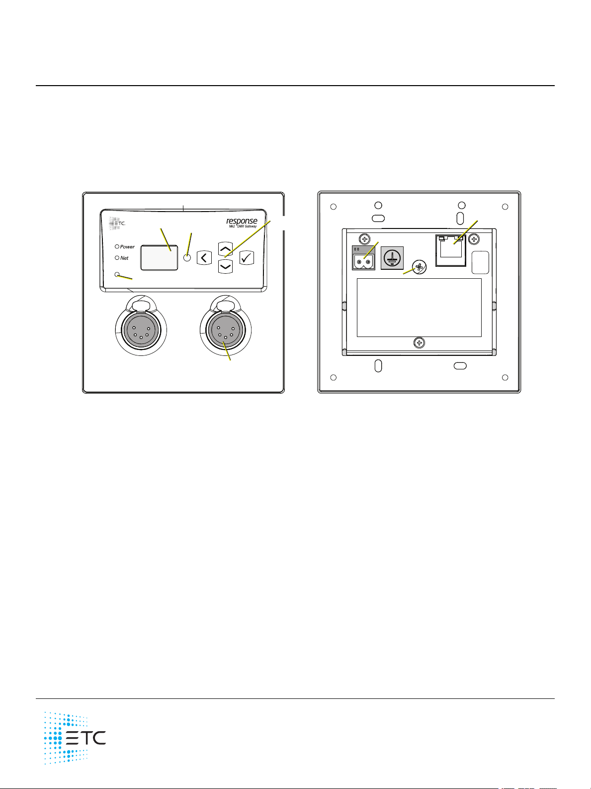
Wall-mount Front View Wall-mount Back View
OLED screen
Touch to
Wake Sensor
Up, Down, Back,
Enter buttons
Reset button
Available connectors:
DMX Out (XLR Female)
DMX In (XLR Male)
DMS RJ45
Aux power
Gr
ound screw
Ethernet
•
•
•
•
•
•
Response Mk2 Two-Port Gateway
This guide covers installation and basic setup of the Re sponse Mk2 Two-Port Gateway. You can
configure additional software features using ETCConcert software. Reference the Help system built
into Concert for more information. ETC Conce rt software can be found at etcconnect.com/Concert.
Overview
There a re two versions of the Two-Port Gateway: a wall-mount version and a portable version.
Action Buttons
Up, Down, Back buttons - T he Ba ck button allows you to return to the previous menu or option
and the Up and Down buttons navigate between menu options
Enter - The Enter button allows you to a dvance to the next available menu option or commit a
modified selection
Reset - The Reset button provides a physical button to reset the gateway
Touch to Wake Sensor - Cove r the sensor with your hand to wake the display
LED Indicators
Power - Solid blue indicates that power is supplied
Network - Solid green indicate s network connection and blinking indicates network activity
Corpora te Headqua rters Middleton, W I, USA +1 608 8 31 4 116 London, UK +44 ( 0) 20 8 89 6 10 00
Holzk irchen, DE +49 (8 0 24 ) 47 0 0- 0 Rom e, IT +3 9 (0 6) 3 2 11 1 683 Hong Kong +852 2799 1220 Pa ris, FR +33 1 42 43 353 5
We b etcconne ct.com Support support.etc conne ct.com Contac t e tcc onnec t.com /conta ctE TC
© 2 02 0 Ele ctronic Thea tre Controls, Inc. Tradem ark and pa tent info:etcc onnec t.com /ip
Product information a nd spe cific ations subject to c hange . E TCintends this doc ument to be provided in its e ntirety.
42 68M22 10 Rev D Released 202 0-08
Page 2
ETC Setup Guide
•
•
•
•
•
1
2
3
4
5
Push
1
2
3
4
5
Push
1 8
Two-Port Gateway
Electrical Specifications
The gateways are powered by either auxiliary power or P ower over Ethe rnet (P oE).
Auxiliary power input rated voltage of 12-24 VDC, 4 W Max, Polarity Independent
10/100Base-T, PoE power Cla ss 1 (IEEE 802.3af)
For auxiliary power, the wall-mount gate wa y use s a two-position screw clamp terminal block. The
portable gate wa y uses a screw locking DCbarrel connector for use with an external power supply
(available separately).
If you supply both PoE and auxiliary power, the gateway defaults to using auxiliary. If auxiliary
power is lost, the gateway will reboot and then begin using PoE.
Note: If you are using an e xternal power supply, it must be rated at a maximum of
15watts.
Connection Options
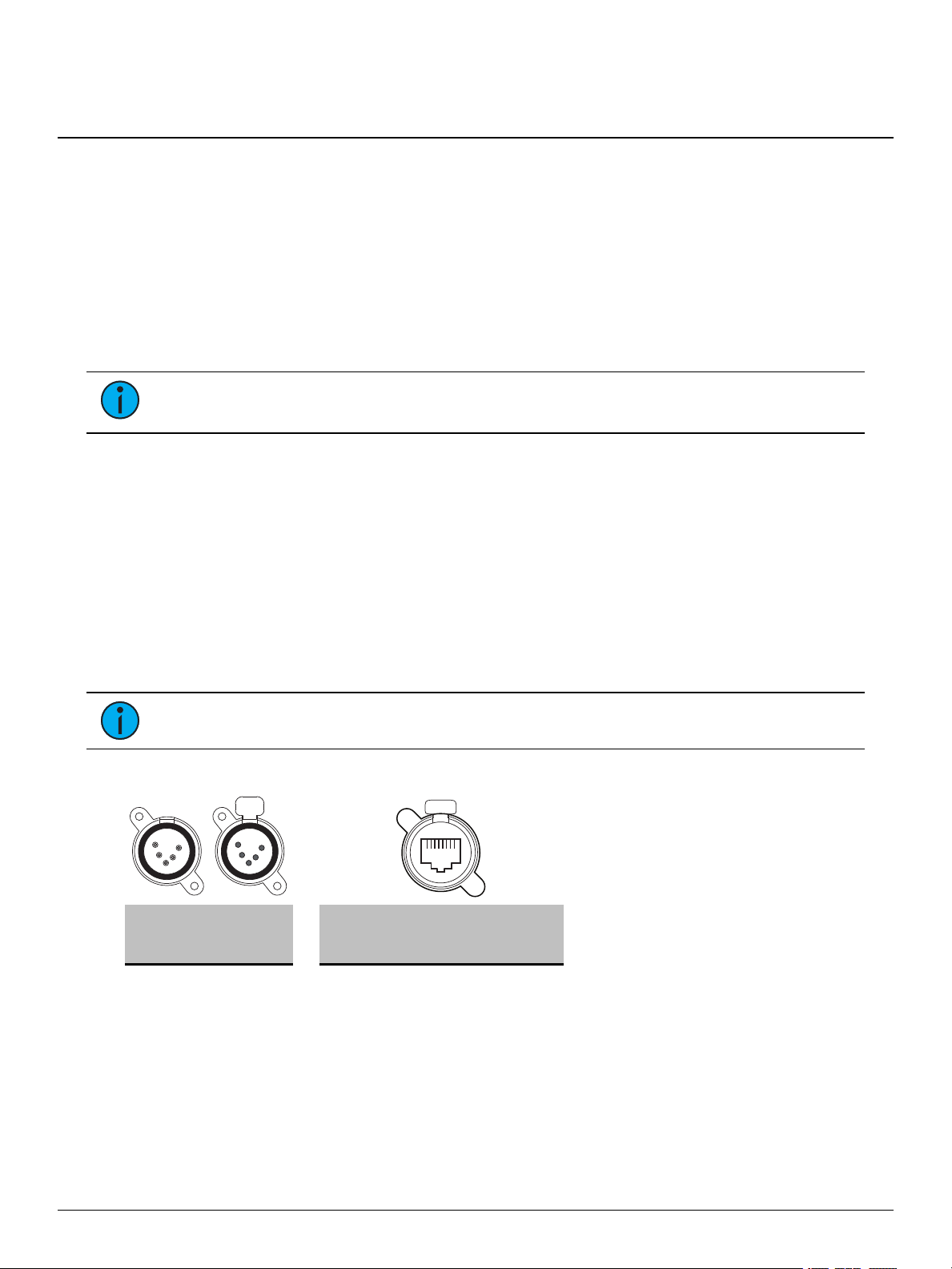
There a re three different connector types available depending on your gateway:
DMX Out (five-pin female XLR)
DMX In (five-pin male XLR)
DMX RJ45 (input or output)
The Response Mk2 Gateways send and receive DMX-512 control signals. DMX cables must be
acceptable for DMX data transmission and conne ctions should follow the standard pinouts per the
charts below. The optiona l secondary data pair is not used by the Response Mk2 Gateways.
The DMX RJ45 varia nt can use a standard RJ45 Cat5e cable or better to transmit DMX-512 to other
devices with the same connector.
Note: The DMX RJ45 connector does not function as an Ethernet network port.
Pinouts
DM X-512
Pinout for
five -pin XLR
Pin Use Pin Use
1 Common (shield) 1 Data 1 + w/orange
2 Data - 2 Data 1 - orange
3 Data + 3 not used w/green
4 not connected 4 not used blue
5 not connected 5 not used w/blue
6 not used green
7 Signal Common w/brown
8 Signal Common brown
DM X-512 Pinout
for RJ45
Wire
Color
Two- Port Gateway Page 2 of 8 ETC
Page 3
ETC Setup Guide
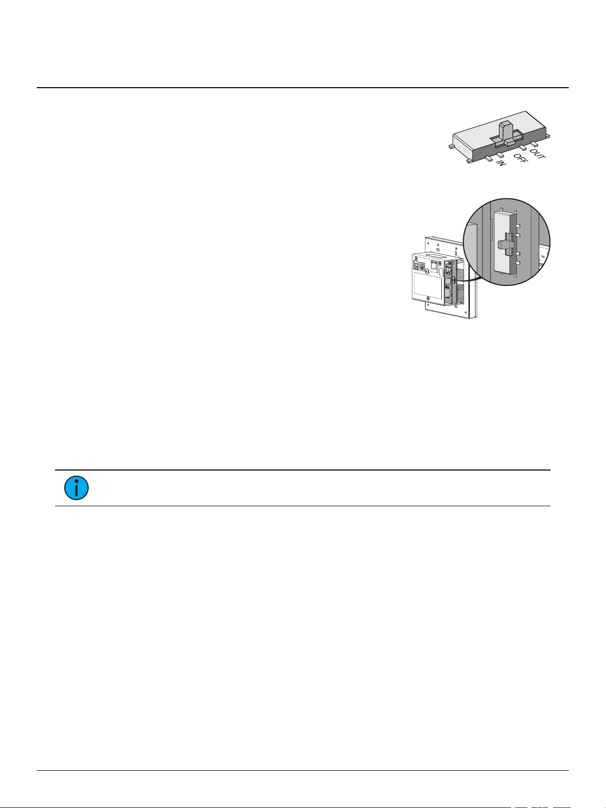
Termination
switch location
Two-Port Gateway
DMX Termination
Te rmina tion is required for all DMX systems and belongs at the source
(be ginning) of a DMX line and at the last device physically connected in
the line. A termination switch is located internally for each input/output
and can be configured for DMX termination (IN), No termination (OFF) or
RDM termination (OUT ). By default, the DMX termination switch is set to
the appropriate position based on the port type (Female XLR and RJ45 set
to OUT and Male XLR set to IN).
If you need to change the termination setting, perform the following steps:
1. Disconnect your gateway from all power supplies.
2. Remove the gateway from the back box or portable
enclosure. The termination switches are between the
two printed circuit boards, one on either side of the
gateway.
3. Se t the termination switch to the a ppropriate
configuration.
About RDM
Remote Device Management (RDM, ANSI E1. 20) is a protocol enhancement to DMX-512 that allows
bidirectional communication between a lighting system controller and attached RDM-compliant
responder devices over a standard DMX line. This protocol allows configuration, sta tus monitoring,
and management of these devices.
An RDM Controller is the device that initiates communica tion with one or more RDM Responder
devices. Examples of responders are RDM-e na bled edge devices such as color scrollers, dimmers,
moving lights, and LED fixtures. Compliant DMX-512 and DMX-512-A devices (non-RDM devices)
are fully functional when RDM is present. The Response Mk2 Gateway supports up to 256 total
RDMdevice s across its ports using standard DMXsystem design practice s.
Note: RDM is currently only supporte d on DMXOutput ports.
RDM Basics
By defa ult, RDM discovery is not e nabled on the gateway. To enable RDM on the gateway, use the
ET C Concert software or the user interface on the front of the gate wa y. Please see the Concert
online help file s for more information on activa ting RDM on your gateways or see
RDMSettings on page 7
.
Configure
Two- Port Gateway Page 3 of 8 ETC
Page 4

ETC Setup Guide
Aux power
Ethernet
Ground screw
Two-Port Gateway
Installation
Note: Installation must follow all nationa l and local codes for electrica l equipment.
The Two-Port gate wa y is available in a wall-mount (for installation into a back box) a nd a portable
(pipe, bar or truss mounted) version.
Wall-Mount
For surface-mount applications, ETC recommends using a n ET Ctwo-gang surface -mount back box
(pa rt# 1064A1038). For flush-mount applications, use an industry standard two-gang, deep back box
or equivalent (provided by others). The back box should be installed plumb and square for best
results. Ensure tha t the box is clean and free of obstructions and that all wiring is installed correctly.
Attach Bezel to Back Box
Before you install your ga te wa y into the back box, you must attach the bezel, a s the wires must pass
through the bezel from the back box. Using the four screws provide d, secure the bezel to the back
box.
Connect Wiring
Pull all required wiring to the ba ck box, including an Ethernet
cable (Category 5e or bette r) a nd ground wire. Terminate the
Ethernet cable using the included kit (part# 4101A2003). T he n
conne ct the termination box to the gateway using the short maleto-male Ethernet cable include d with the kit.
If you are using auxiliary power, perform the following steps:
1. Run the supply wires to the back box, lea ving a 300 mm
(12 in) tail.
2. Strip 5 mm (3/16 in) of insulation from the ends of the
incoming wires.
3. Insert the positive wire into the left hand screw terminal
and tighten the termina l screw to
Two- Port Gateway Page 4 of 8 ETC
7 in-lb (0.5 Nm).
4. Insert the negative wire into the right hand terminal of the
conne ctor and tighten the terminal screw to 7 in-lb ( 0.5
Nm).
5. Conne ct the two-pin conne ctor to the port on the back of the gateway.
Page 5

ETC Setup Guide
Latch locks extend through plate
Secure bottom magnets
Press in top and secure face plate
Ethernet
DC power
input
Ground point
Mounting
bracket
Two-Port Gateway
6. Using the harness and WAGO®conne ctor provided, connect the ground wire to the ground
screw on the back of the unit.
Install into Back Box
1. Insert the gateway electronics and wiring through the bezel and into the back box.
2. Using the four screws (M4 x 6 mm) provided, secure the gateway to the bezel.
3. Attach the face pla te to the front of the gateway. To do this, you must align the face plate so
that the port latch locks (PUSH buttons) are centered on the port hole s.
4. With the top of the fa ce plate angled slightly away from the gateway, move the plate so the
latch locks extend through the plate.
5. Shift the plate down until the bottom magnets secure the plate to the gateway and then press
in the top so the entire face plate is secure .
Portable
The portable version of the gateway is designed for easy
setup and can be mounted using the mounting bracket. The
bracket contains holes that accommodate standard mounting
hardware (available separately).
Once you have mounte d the portable gateway, connect an
RJ45 cable to the connector on the side of the unit. If you are
not using PoE to power the gateway, connect a compatible
power supply (available separa te ly) to the ba rre l connector
on the side of the gateway.
If you are not using either a grounded etherCON connector
or DCpower supply, use the ground point to connect the
gateway to a suitable earth ground point.
Two- Port Gateway Page 5 of 8 ETC
Page 6

ETC Setup Guide
DMX Gateway
1
0
.101.101.101
1 12 2 50
3à...
ß à
4à100
•
•
•
1 DD
1 AIPß
1^
1 X
à
•
•
Ver: 1.0.0.12
FP
GA: 1.0.0
Network
Port 1
Ch
annel 1
State Active
Level 127(50%)
Port 1
Mo
de Output
U: 63999
Speed Max
Port 1
R
D
M Enabled
Background Off
Devices 128
•
•
•
Two-Port Gateway
Gateway User Interface and Configuration
The following sections provide information on basic tasks and configuration that you can perform
from the user interface of the gateway. These tasks and additional configuration can all be
performed using the ETC Concert application, available from etcconnect.com.
Home Screen Information
The initia l screen that your gateway displa ys is the Home screen, which provides
the name of the gateway, the IPaddress and some basic port information. This
image is what a typical home screen might look like on a four-port gateway,
where the gateway name is DMXGateway and IPaddress is 10.101.101.101.
Additionally, the port information provides the following:
Port 1 is
universe 12.
Port 2 is
50. If an inactive port is in data-loss behavior, such as holding, the port number is appended
with an asterisk.
Port 3 is not a ctively outputting DMXand
ellipsis (...) indicates additional informa tion that can be vie we d from the About scree n.
Port 4 is actively outputting DMXfrom universe 100.
Additionally, DD indicates a dimmer-doubled port, AIP indicate s Advanced Input
Pa tch, ^ indicates a port in downloa de r mode, and X indicates a disabled port.
actively
(black background)
not actively
receiving
(white background)
(left-facing arrow) DMXinput and sending it to
outputting
either has a unive rse above 999 or is split
(right-fa cing arrow) DMX from unive rse
. The
Pressing the Ente r button from the Home screen brings up three selectable menu options
(About, S e tup, O pera tions) from which you can access other informa tion or
configuration options.
If you receive a Use r Inte rface Lock e d message when accessing the Setup or O perations options,
the gateway UI is locked. To unlock the UI, you must use the ETC Concert software.
View Device Information
To view information specific to your gateway, select the About menu option from the Home scree n.
From the About screen, you can select one of the following four options and then view the
information specific to tha t option:
Genera l View Leve ls Port Info RDM Info
Configure Network Settings
1. From the Home screen, select Setup >Network.
2. From the Mode screen, use the Up and Down buttons to select Ma nual, Link Local or
Automatic.
Automatic attempts to automa tically configure the IP Address, IPSubnet and IPGa teway for
your device via DHCP .
If you select Manual, you must configure the IPAddress, IPSubne t and IPGateway scre ens
and the n select O K from the Apply/ Reboot? screen.
If you select Link Local, the gateway self-assigns an IPaddress that is valid for the local
network in the link-local address range. Select OK from the Apply/Reboot? scree n.
Two- Port Gateway Page 6 of 8 ETC
Page 7

ETC Setup Guide
•
•
•
•
•
•
•
•
•
Two-Port Gateway
Configure Port Settings
1. From the Home screen, select Setup >Ports.
2. Use the Ente r button to move from the menu options on the left to the values on the right side
of the screen. Use the U p and D own buttons to change the values and press Enter again to
confirm the cha nge. Using these controls, configure the fields on screen:
Port - Select the port for which the following values apply:
Mode - Select the port mode. This can be set to Input, O utput or Disabled.
Univ e rse - Se lect the Universe of the port (1-63999).
Speed - Select the speed at which DMXis transmitted. This can be set to S low, Medium, Fast,
and Max.
Note: For de ta ile d DMXspeed timings, visit:
https://support.e tcconnect.com/ETC/FAQ/DMX_ Speed.
Configure RDMSettings
1. From the Home screen, select Setup >RDM.
2. Use the Ente r button to move from the menu options on the left to the values on the right side
of the screen. Use the U p and D own buttons to change the values and press Enter again to
confirm the cha nge. Using these controls, configure the fields on screen:
Port - Select the port for which the following values apply:
RDM - S elect whether RDMis ena bled or disabled on the port.
Background - S elect whether background discovery and polling of RDM is on or off.
Configure Data Loss Settings
1. From the Home screen, select Setup >Data Loss.
2. Use the Enter button to move from the menu options on the left to the values on the right side
of the screen. Use the Up and Down buttons to change the value s and press Enter again to
confirm the cha nge. Using these controls, configure the fields on screen:
Port - Select the port for which the following values apply:
HLLF - Select whethe r Hold Last Look Forever (HLLF)is on or off. Selecting On enables Hold
Last Look Forever. Additional configuration options for hold last look are available in Concert.
Two- Port Gateway Page 7 of 8 ETC
Page 8

ETC Setup Guide
Restore Defaults
Al
l data
will be lost
OK?
Update Software
from s
erver
10.101.50.60
OK?
Port 1
St
ate Release All
•
•
•
Two-Port Gateway
Restore Default Settings
To restore the factory defaults for your device, select the Opera tions menu from
the home screen and choose the Re store Defa ults option. T his remove s all
network and master/backup information that is configured for your gateway but
retains the gateway name.
Update Software
The recommended method of upda ting the gate wa y is through UpdaterAtor. The UpdaterAtor
application is available for download at etcconnect.com.
There is also an option to update the software from the gateway using a TFTP
serve r like Conductor. To upgrade the software, select the Opera tions menu from
the home screen and choose the Upda te Softwa re option. If you do choose to
update directly from the gateway, the bootloader runs and the latest software is
downloaded from the server indicate d by the <#.#.#.#> IP address on the Update
Software screen. If you need to modify this IP address, you can configure it in the
Concert application using the Upda te Serve r property.
Note: Regardless of whe ther you update from UpdaterAtor or dire ctly from the gateway,
the device must be on the network.
Test Port Output
You can test DMX outputs by selecting Operations >Test Output from the Home screen.
CAUTION : Testing outputs drives all DMXle vels to full. Use with cauti on in a
show situa tion or when controlling high current devices.
This scree n allows you to test the output for any port on your gateway.
Port - Press the Enter button to sele ct and then use the Up and Down buttons to cycle through
the ports of your gateway. Press Enter again to select the port.
State - Press Enter to select and then use the Up and Down buttons to cycle through the test
state options. If the port is an input, this field displays either Input or Disabled. If the port is an
output, you can select either Released (--), Full or All Zero.
Release All - Press the Enter button to release the test state on all ports. Once outputs are set
into a test state they can be released from this menu, from Concert or by rebooting the
gateway.
Note: This product uses licensed software provided by third parties. Please visit
http://www.etcconnect.com/licenses/ for licensing information.
Two- Port Gateway Page 8 of 8 ETC
 Loading...