

Page 1
ETC Setup Guide
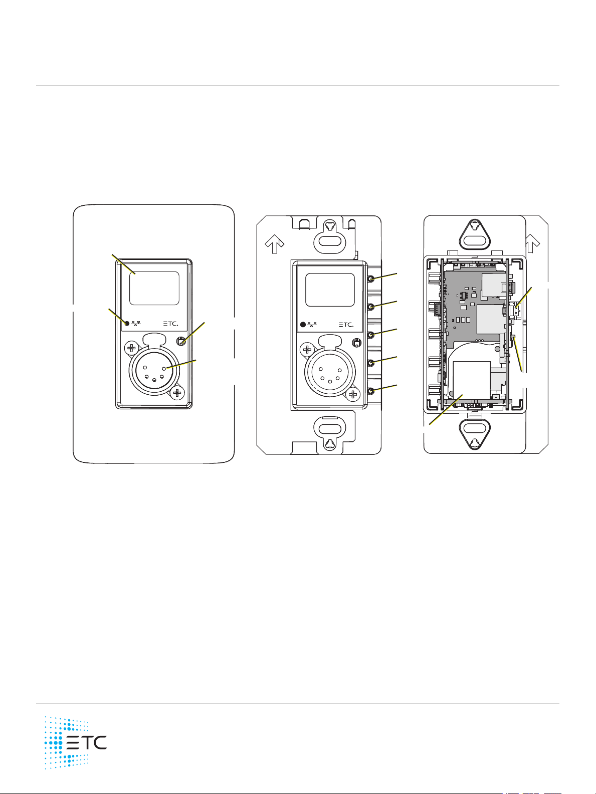
Wall-mount Front View with Faceplate
Touch to
Wake Sensor
OLED screen
Network indicator
Available connectors:
DMX Out (XLR Female)
DMX In (XLR Male)
DMX RJ45
Wall-mount Back View
Wall-mount Front View
Up
button
Down
button
Left
button
Enter
button
Reset
button
Ethernet
Aux power
Termination
switch
•
•
•
•
•
Response Mk2 One-Port Gateway
This guide covers installation and basic setup of the Re sponse Mk2 One-Port Gateway. You can
configure additional software features using the Ne t3 Concert software from ET C. Reference the Help
system built into Concert for more information. Net3 Concert software can be found at
etcconnect.com/ Concert.
Overview
There a re two versions of the O ne -Port Gate wa y: a wall-mount version and a portable version.
Action Buttons
Up, Down, Back buttons - T he Ba ck button allows you to return to the previous menu or option
and the Up and Down buttons navigate between menu options
Enter - The Enter button allows you to a dvance to the next available menu option or commit a
modified selection
Reset - The Reset button provides a physical button to reset the gateway
Touch to Wake Sensor - Cove r the sensor with your hand to wake the display
LED Indicators
Network - Solid green indicate s network connection and blinking indicates network activity
Corpora te Headqua rters Middleton, WI, USA +1 60 8 831 4116 London, UK +44 (0 )2 0 88 96 100 0
Holzk irchen, DE +49 (8 0 24 ) 47 0 0- 0 Rom e, IT +3 9 (0 6) 3 2 11 1 68 3 Hong Kong +852 2799 122 0 Pa ris, FR +33 1 42 43 3535
We b etcconne ct.com Support support.etc connect.com Contac t e tcc onnect.com /contactETC
© 2 019 Ele ctronic T hea tre Controls, Inc. Tradem ark a nd pa tent info:etcc onnect.com /ip
Product information a nd specific ations subject to c hange . E TCinte nds this docum ent to be provided in its entirety.
42 68M22 20 Rev A Released 2019-07
Page 2
ETC Setup Guide
•
•
•
•
•
1
2
3
4
5
Push
1
2
3
4
5
Push
1 8
One-Port Gateway
Electrical Specifications
The gateways are powered by either auxiliary power or Power over Ethernet (P oE ).
Auxiliary power input rated voltage of 12-24 VDC, 4 W Max, Polarity Independent
10/100Base-T, PoE power Class 1 (IEEE 802.3af)
For auxiliary power, the wall-mount gate wa y includes a red-and-black wire harness that connects to
the supply conductors using two-position WAGO®conne ctors. T he portable gateway uses a screw
locking DCbarrel connector for use with an external power supply (available separately).
If you supply both PoE and auxiliary power, the gateway defaults to using auxiliary. If auxiliary
power is lost, the gateway will reboot and then begin using PoE.
Note: If you are using an e xternal power supply, it must be rated at a maximum of
15watts.
Connection Options
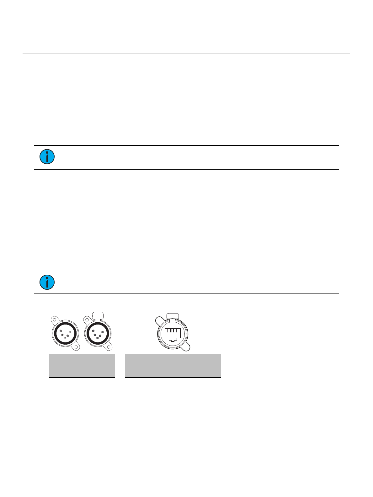
There a re three different connector types available de pending on your gateway:
DMX Out (five-pin female XLR)
DMX In (five-pin male XLR)
DMX RJ45 (input or output)
The Response Mk2 Gateways send and receive DMX-512 control signals. DMX cables must be
acceptable for DMX data transmission and connections should follow the standard pinouts per the
charts below. T he optiona l secondary data pair is not used by the Response Mk2 Gateways.
The DMX RJ45 varia nt can use a standard RJ45 Cat5e cable or better to transmit DMX-512 to other
devices with the same connector.
Note: The DMX RJ45 connector does not function as an Ethernet network port.
Pinouts
DM X-512
Pinout for
five -pin XLR
Pin Use Pin Use
1 Common (shield) 1 Data 1 + w/orange
2 Data - 2 Data 1 - orange
3 Data + 3 not used w/green
4 not connected 4 not used blue
5 not connected 5 not used w/blue
6 not used green
7 Signal Common w/brown
8 Signal Common brown
DM X-512 Pinout
for RJ45
Wire
Color
One-Por t Gateway Page 2 of 8 ETC
Page 3
ETC Setup Guide
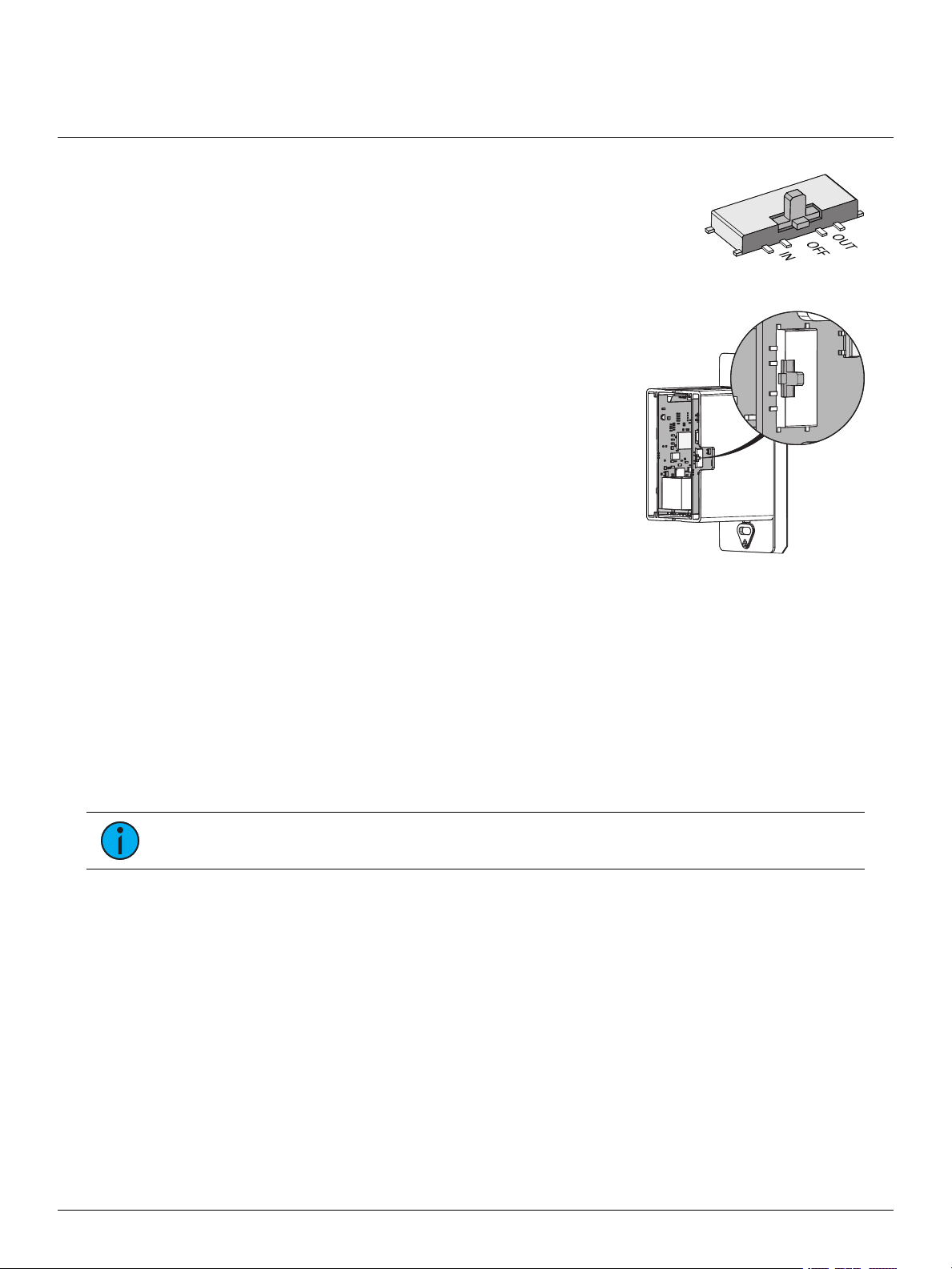
Termination
switch location
One-Port Gateway
DMX Termination
Te rmina tion is required for all DMX systems and belongs at the source
(be ginning) of a DMX line and at the last device physically conne cted in
the line. A termination switch is located internally for each input/output
and can be configured for DMX termination (IN) , No termination (OFF) or
RDM termination (OUT ). By default, the DMX termination switch is set to
the appropriate position based on the port type (Female XLR and RJ45 set
to OUT and Male XLR set to IN).
If you need to change the termination setting, perform the following steps:
1. Disconnect your gateway from all power supplies.
2. Remove the face plate and gateway from the back
box or portable enclosure. If you are looking at the
back of the gateway, the termination switch is on the
exterior of the right side, beneath the auxiliary power
conne ctor.
3. Se t the termination switch to the a ppropria te
configuration.
About RDM
Remote Device Management (RDM, ANSI E1.20) is a protocol enha ncement to DMX-512 that allows
bidirectional communication between a lighting system controller a nd attached RDM-compliant
responder devices over a standard DMX line. This protocol allows configuration, sta tus monitoring,
and management of these devices.
An RDM Controller is the device that initiates communica tion with one or more RDM Responder
devices. Examples of responders are RDM-enabled edge devices such as color scrollers, dimme rs,
moving lights, and LED fixtures. Compliant DMX-512 and DMX-512-A devices (non-RDM devices)
are fully functional when RDM is present. The Response Mk2 Gateway supports up to 256 total
RDMdevices across its ports using standard DMXsystem design practice s.
Note: RDM is currently only supporte d on DMXOutput ports.
RDM Basics
By defa ult, RDM discovery is not e na bled on the gateway. To enable RDM on the gateway, use the
Net3 Concert software or the user interface on the front of the gateway. Please see the Concert
online help file s for more information on activating RDM on your gateways or see
RDMSettings on page 7
Configure
.
One-Por t Gateway Page 3 of 8 ETC
Page 4

ETC Setup Guide
Ethernet
Ground wire
Aux Power
One-Port Gateway
Installation
Note: Installation must follow all nationa l and local codes for electrica l equipment.
The One-Port gateway is ava ila ble in a wa ll-mount (for installation into a back box) and a portable
(pipe, bar or truss mounted) version.
Wall-Mount
For surface -mount applications, ETC recommends using a n ET Cone-gang surface-mount back box
(pa rt# 1064A1037). For flush-mount applications, use a RACO #695 back box or equivalent
(provided by others). The back box should be installed plumb and square for best results. Ensure that
the box is clean and free of obstructions and that all wiring is installed correctly.
Connect Wiring
Pull all required wiring to the ba ck box, including an
Ethernet cable (Category 5e or better) and ground wire.
Te rmina te the Ethernet cable using the included k it
(pa rt# 4101A2003). Then connect the termination box to
the gateway using the short male-to-male Ethernet cable
included with the kit.
If you are using auxiliary power, perform the following
steps:
1. Locate the 15 cm (6 in) red-and-black wire ha rne ss
that came with your gateway.
2. Using the two-position W AGOconnectors
provided with your gateway, connect the red
(positive) wire to one of them and the black
(ne ga tive) wire to another.
3. Run the 24 VDCwires for your auxiliary power to
the WAGO connectors.
4. Plug the two-pin connector on the e nd of the redand-black wire harness into the power supply
terminal connector on the P CB (located directly
above the te rmina tion switch on the side of the
gateway).
5. Conne ct the ground wire to a suitable grounding point.
One-Por t Gateway Page 4 of 8 ETC
Page 5

ETC Setup Guide
Ethernet
DC power
input
Ground
point
Mounting
bracket
One-Port Gateway
Install into Back Box
1. Insert the gateway electronics and wiring into the back box.
2. Se cure the gateway to the back box using the two screws provided.
3. Align the top of the face plate to the station a nd angle the bottom approximately 20 degrees.
4. Hook the top of the fa ce plate to the tabs on the top of gateway.
5. Swing the bottom of the face plate down until the magnets engage.
6. If the wall pla te does not fully attach, wiggle the bottom of the plate until all the magnets are
seated properly and the plate is secure.
Portable
The portable version of the gateway is designed for easy
setup and can be mounted using the mounting bracket. The
bracket contains holes that accommodate standard
mounting hardwa re (available separate ly).
Once you have mounte d the portable gateway, connect an
RJ45 cable to the connector on the side of the unit. If you are
not using PoE to power the gateway, connect a compatible
power supply (available separate ly) to the barrel connector
on the side of the gateway.
If you are not using either a grounded etherCON connector
or DCpower supply, use the ground point to connect the
gateway to a suitable earth ground point.
One-Por t Gateway Page 5 of 8 ETC
Page 6

ETC Setup Guide
DMX Gateway
10.101.101.101
1 : Output - Act
Univ 63999
1
Ver: 1.0.0.12
FPGA: 1.0.0
MAC
00:c0:16:00:00:00
Port 1
Channel 1
State Active
Level 127(50%)
Port 1
Mode Output
U: 63999
Speed Max
Port 1
RDM Enabled
Background Off
Devices 128
•
•
•
One-Port Gateway
Gateway User Interface and Configuration
The following sections provide information on basic tasks and configuration that you can perform
from the user interface of the gateway. These tasks and additional configuration can a ll be
performed using the Ne t3 Concert application, available from etcconnect. com.
Home Screen Information
The initial screen that your gateway displays is the Home screen. This screen provides the name of
the gateway, the IPaddress and some basic port information. The following is an example of what a
typical home screen might look like.
Here, you'll see that the gateway name is DMXGateway, IPaddress is 10.101.101.101 and port 1 is
actively outputting DMXfrom universe 63999.
Pressing the Ente r button from the Home scre en brings up three selectable menu options (About,
Setup, Opera tions) from which you can access other information or configuration options.
If attempting to a ccess the Se tup or O perations options displays User Interface Locked, your
gateway UI has been locked from the Net3 Conce rt applica tion. To unlock the UI, reference the
Device Help for Re sponse Gate way Mk2 in Net3 Concert software.
View Device Information
To view information specific to your gateway, select the About menu option from the Home scree n.
From the About screen, you can select one of the following four options and then view the
information specific to tha t option:
Genera l View Leve ls Port Info RDM Info
Configure Network Settings
To configure ne twork settings for your gateway, perform the following steps:
1. From the Home screen, select Setup >Network.
2. From the Mode screen, use the Up and Down buttons to select Ma nual, Link Local or
Automatic.
Automatic attempts to automa tically configure the IP Address, IPSubnet and IPGa te wa y for
your device via DHCP .
If you select Manual, you must configure the IPAddress, IPSubne t and IPGateway screens
and the n select O K from the Apply/ Reboot? screen.
If you select Link Local, the gateway self-assigns an IPaddress that is valid for the local
network in the link-local address range. Select OK from the Apply/Reboot? scree n.
One-Por t Gateway Page 6 of 8 ETC
Page 7

ETC Setup Guide
•
•
•
•
•
•
•
Restore Defaults
All data
will be lost
OK?
Update Software
from server
10.101.50.60
OK?
One-Port Gateway
Configure Port Settings
To configure the ports of your gateway, perform the following steps:
1. From the Home screen, select Setup >Ports.
2. Use the Ente r button to move from the menu options on the left to the values on the right side
of the screen. Use the U p and D own buttons to change the values and pre ss Enter again to
confirm the cha nge. Using these controls, configure the fields on screen:
Port - Select the port for which the following values a pply:
Mode - Select the port mode. This can be set to Input, O utput or Disabled.
Univ e rse - Select the Universe of the port (1-63999).
HLL - Select whether Hold Last Look (HLL)is on or off. Selecting On enables Hold Last Look
Forever. By default, the output holds for five minutes. Additional configuration options are
available through Net3 Concert.
Configure RDMSettings
To configure RDMfor your gate wa y, perform the following steps:
1. From the Home screen, select Setup >RDM.
2. Use the Ente r button to move from the menu options on the left to the values on the right side
of the screen. Use the U p and D own buttons to change the values and pre ss Enter again to
confirm the cha nge. Using these controls, configure the fields on screen:
Port - Select the port for which the following values a pply:
RDM - S elect whether RDMis ena bled or disable d on the port.
Background - S elect whether ba ckground discovery and polling of RDM is on or off.
Modify Device Settings
To restore the factory defaults or upgrade the software for your device, select the Opera tions menu
from the Home screen. From here, you can select the following options:
Restore Defaults - Select OK? from the Restore De faults scre en to restore all default values to your
device. This removes all information tha t is configured for your gateway.
Update Software - S elect OK? from the Update Software from server <#.#.#.#> scree n if you need
to update the softwa re directly from the gateway.
Note: The recommended method of updating is through UpdaterAtor. Regardless of
whether you update from UpdaterAtor or directly from the gateway, the device must be on
the network.
If you do choose to update directly from the gateway, the bootloader runs and the latest software is
downloaded from the server indicate d by the <#.#.#.#> IPaddress on the Upda te S oftware scree n. If
you nee d to modify this IPaddress, you can configure it in the Net3 Concert application using the
Update Server property.
One-Por t Gateway Page 7 of 8 ETC
Page 8

ETC Setup Guide
Port 1
State Release All
•
•
•
One-Port Gateway
Test Port Output
You can test DMX outputs by selecting Operations >Test Output from the Home screen.
CAUTION : Testing outputs drive s all DMXlevels to full. Use with caution in a
show situa tion or when controlling high current de vices.
This scree n allows you to test the output for any port on your gateway.
Port - Press the Enter button to sele ct and then use the Up and Down buttons to cycle through
the ports of your gateway. Press Enter again to select the port.
State - Press Enter to select and then use the Up and Down buttons to cycle through the test
state options. If the port is an input, this field displays either Input or Disabled. If the port is an
output, you can select either Released (--), Full or All Zero.
Release All - Press the Enter button to release the test state on a ll ports. Once outputs are set
into a test state they can be released from this menu, from the Net3 Concert application or by
rebooting the ga te wa y.
One-Por t Gateway Page 8 of 8 ETC
Note: This product uses licensed software provided by third parties. Please visit
http://www.etcconnect.com/licenses/ for licensing information.
 Loading...