

Page 1
ETC Setup Guide
Up, Down, Back,
Enter buttons
Alternative Ethernet
location
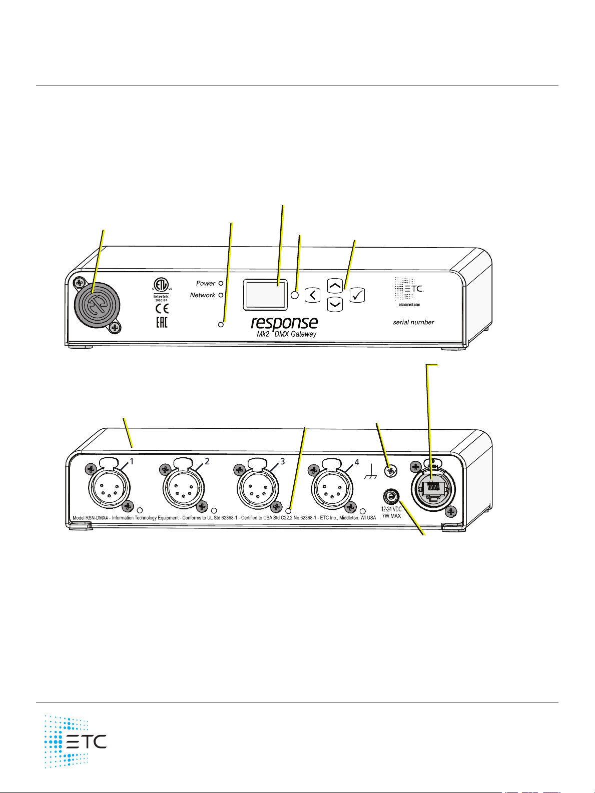
Available configurations:
4-DMX Out (XLR Female)
4-DMX In (XLR Male)
1-DMX In 3-DMX Out
4-DMX Terminal
4-DMX RJ45
Port indicator
OLED screen
DC power input
Default Ethernet location
PoE (IEE 802.3af)
10/100Mbps data speeds
Auto-sensing
Auto-negotiation
RJ45 and etherCON compatible
Reset button
Touch to
Wake Sensor
Ground screw
•
•
•
•
Response Mk2 Four-Port Gateway
This guide covers installation and basic setup of the Response Mk2 Four-Port Gateway. You can
configure additional software fea tures using ETCConcert software. Reference the Help system built
into Concert for more information. ETC Concert software can be found at etcconnect.com/Concert.
Overview
The Four-Port Gateway can be used on a tabletop or be rack-, pipe- or bar-mounted using optional
accessories (availa ble separately).
Action Buttons
Up, Down, Ba ck buttons - The Back button allows you to return to the previous menu or option
and the Up and Down buttons navigate between menu options
Enter - The Enter button allows you to adva nce to the ne xt availa ble menu option or commit a
modified selection
Reset - The Reset button provides a physical button to reset the gateway
Touch to Wake Sensor - Cover the sensor with your hand to wak e the display
Corpora te Hea dquarte rs Middleton, WI, USA +1 608 831 4116 London, UK +44 (0)20 8896 1000
Holzk irchen, DE +49 (80 24) 47 0 0- 0 Rome , IT +39 (06 ) 32 111 683 Hong K ong +852 2799 122 0 Paris, FR +33 1 42 43 3535
We b etcconne ct.c om Support support.etcc onnect.com Contact e tcc onnec t.com /conta ctE TC
© 2 019 Electronic T heatre Controls, Inc . T rade ma rk and pa tent info:etcc onnect.com/ip
Product information a nd specifications subjec t to change. ETCintends this doc ument to be provided in its entirety.
42 68M22 00 Rev B Re lea sed 2019-10
Page 2
ETC Setup Guide
•
•
•
-
-
-
-
-
-
-
-
-
-
-
-
•
•
Four-Port Gateway
LED Indicators
Power - Solid blue indicate s that power is supplied
Network - Solid green indicates network connection and blinking indicates network activity
Port Indica tor - Each port has an adjacent port indicator LED that provides information on the
state of the port:
Output mode
Gree n (solid): Valid sACNsources on the port
Gree n (slow blinking): No va lid sACN source s on the port. Note tha t the port can be in a
Hold La st Look (HLL) state.
Gree n (fast blinking): Attempting to output but there are other DMXsources dete cted on
the DMXline causing a collision
Amber (blink): RDMtransa ction in process
Input mode
Red (solid): Active DMXinput on the port
Red (slow blinking): No active DMXinput on the port
Red (fast blinking) : DMXsource is invalid
Off: Port disabled or power off
Red-Green (alternating blinking): The port is upda ting a connected ETCdevice
Amber-Green (alternating blinking): The port is in DMXtest mode
Electrical Specifications
The gateways are powered by either auxiliary powe r or Power over Ethernet (PoE).
Auxiliary power input rated voltage of 12-24 VDC, 15 W Max, Polarity Independent
10/100Base-T, PoE power Class 2 (IEE E 802.3af)
For auxilia ry power, the gateway uses an external DCpower supply (available separately).
If you supply both PoE and auxiliary power, the gate way defaults to using a uxiliary. If auxilia ry
power is lost, the gate wa y will reboot and the n begin using PoE.
Note: If you are using an e xternal power supply, it must be rated at a maximum of
15watts.
Four - Port Gateway Page 2 of 10 ETC
Page 3
ETC Setup Guide
•
•
•
•
•
•
•
•
•
1
2
3
4
5
Push
1
2
3
4
5
Push
1 8
1 3
Four-Port Gateway
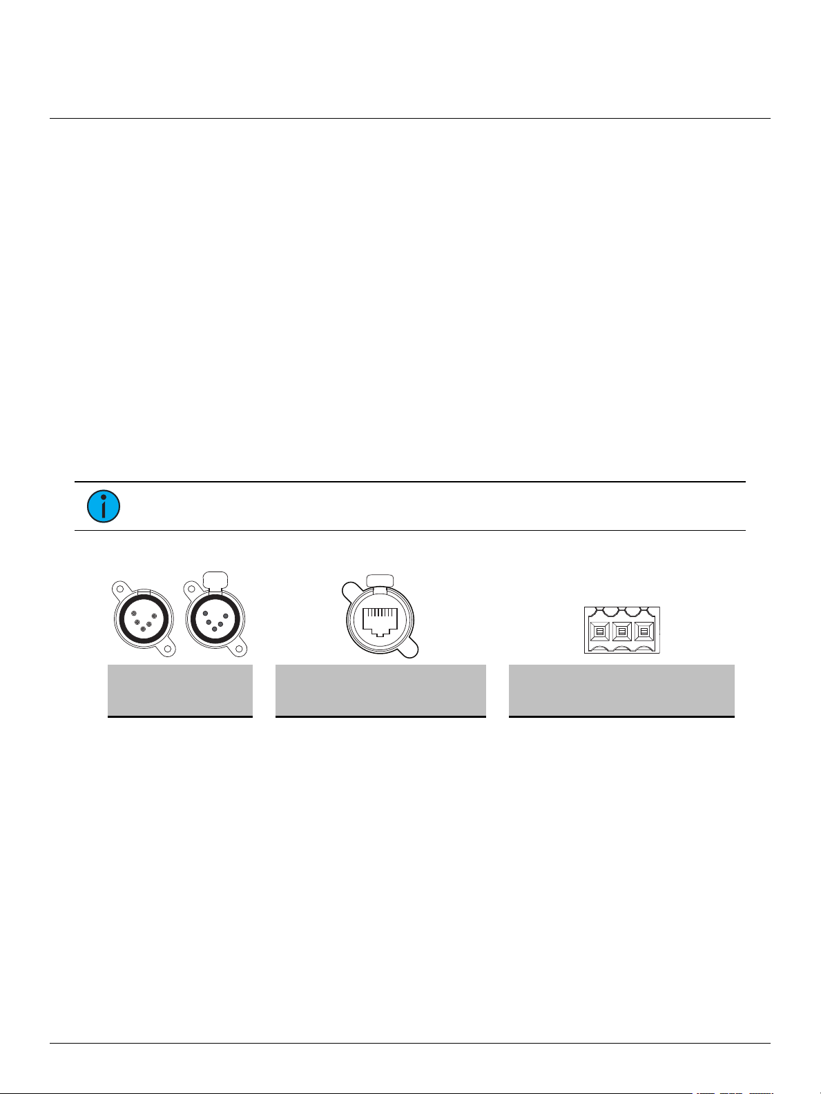
Connection Options
There are four different connector types available depending on your ga tewa y:
DMX Out (five-pin female XLR)
DMX In (five-pin male XLR)
DMX RJ45 (input or output)
DMX Terminal he ader (three-pin terminal for input or output)
The Response Mk2 Gateways send and rece ive DMX-512 control signals. DMX cables must be
acceptable for DMX data transmission and connections should follow the standard pinouts pe r the
charts below. The optional seconda ry data pa ir is not used by the Response Mk2 Gateways.
The DMX RJ45 variant can use a standa rd RJ45 Cat5e cable or better to transmit DMX-512 to other
devices with the same connector.
The Four-Port Gateway is available in five va riants of available connector types:
4 Out (female XLR connectors)
4 In (male XLR connectors)
3 Out and 1 In
4 Terminal connectors
4 RJ45 connectors
Note: The DMX RJ45 connector does not function as an Etherne t ne twork port.
Pinouts
DM X-512
Pinout for
five -pin XLR
Pin Use Pin Use
1 Common (shield) 1 Data 1 + w/orange 1 Common (shield) clear/shie ld
2 Data - 2 Data 1 - orange 2 Data - black
3 Data + 3 not used w/green 3 Data + red
4 not connected 4 not used blue
5 not connected 5 not used w/blue
6 not used green
7 Signal Common w/brown
8 Signal Common brown
DM X-512 Pinout
for RJ45
Wire
Color
DM X-512 Pinouts for
Terminal He a der
Pin Use
Typica l
Wire Color
Four - Port Gateway Page 3 of 10 ETC
Page 4

ETC Setup Guide
•
•
D1
12
10
11
12
8
5
5
6
7
3
+-
com
Four-Port Gateway
Wiring the Terminal Connector
The terminal header can accept two type s of connectors (both connector types are provided with the
gateway):
DMXCable (three-position screw connector used with Belden 9729 or equivalent cable)
DMXCat5 (three-position Cat5 insula tion displaceme nt connector used with Ca t5 or
equivalent cable)
DMXCable Preparation and Termination
Note: Not for use with Cat5, Cat5e, or Cat6 cable. When running DMXwith the se cable
types, use the provided 3-position IDCconne ctor and reference DMXCat5 Pre pa ra tion and
Te rmination on the facing page.
This instruction assumes preparation of Belden 9729 (or equivalent) cable for termination to the
three-position screw terminal connector provided.
1. Install the cable so there is an 20 cm (8 in) service
loop available at the re ar of the gateway.
2. Strip 18 cm (7 in) off the outer jacket.
3. Label the cable with the data type and run
designation. (DMX1, DMX2, etc.)
4. Strip the foil shie lding from each wire set to within
6 mm (1/4 in) of the outer jacket.
5. Untwist the shield wire from each pair and apply a
piece of 1.6 mm (1/16 in) clear heat shrink to each
shield wire.
6. Twist each shield wire back onto its data pair, and
then apply a 4 cm (1.5 in) piece of 0.5 cm (3/16 in)
heat shrink all the wa y down each 3-wire set. Make
sure to capture the foil shie lding at the base.
7. Apply the 5 cm (2 in) piece of the 1 cm (3/8 in) heat
8. Cap the ends of the unused pair of wires with a
9. Strip 6 mm (1/4 in) of insulation from all of the wires
10. Maintain the wire pair twist as close to the screw
11. Bend back the unused set of wires and secure them to the cable with a wire tie.
12. Secure the terminated wire sets together with a wire tie 5 cm (2 in) from the connector.
shrink, centered on the end of the cable jack et and
the bases of all the wires in the cable.
2.5 cm (1 in) piece of 0.5 cm (3/16 in) heat shrink
centered over the end of the wires.
to be used.
terminal connector as possible and terminate the
wires.
a. Insert the common (shield) wire into the
terminal labeled “DMX " and secure.
b. Insert the data - wire (typically black) into the
terminal labeled “DMX -” a nd secure.
c. Insert the data + wire (typically red or white)
into the terminal labeled “DMX +” and secure.
Four - Port Gateway Page 4 of 10 ETC
Page 5

ETC Setup Guide
C
OM W/
BRN
Data -
O
R
G
Dat
a
+
(
W/O
RG)
•
•
•
Screws for cover removal
Four-Port Gateway
DMXCat5 Preparation and Termination
This instruction assumes use of Cat5 (or equivalent) cable for termination to the three-position Cat5
insulation displa cement connector provided in the termina tion kit.
1. Follow normal Cat5 wire installation procedures to remove 5 cm ( 2 in) from the
end of the cable ja cket.
2. Se pa rate the White/Brown, Orange, and White/Orange conductors from the
cable. These conductors are required for DMX out.
3. Cut the remaining unused conductors from the cable flush to the cable ja cket.
4. Label the cable with the data type and run designation
(for example D1 for DMX run 1).
5. Twist the White/Orange a nd O range conductors as close to the 3-position IDC
as possible and insert the conductors through the labele d termina ls as follows:
Common (White/Brown) to terminal 1
Data - (Orange) to terminal 2
Data + (White /Orange) to terminal 3
6. Fully depress each te rminal, closing it onto the wire.
7. Use side-cutters to trim the excess wire from the connector.
Switching the Network Port
The Response Mk2 Four-Port Gateway can have the Ethernet connector installed on the front or
back of the unit. To switch the location, pe rform the following steps:
1. Using a Phillips screwdrive r, remove the four
screws on the bottom of the gateway and slide
the cover off from front to back.
2. Using a Phillips screwdrive r, remove the two
screws from the nuts securing the blank plate to
the gate wa y.
3. Remove the two scre ws securing the Ethernet
conne ctor to the gateway.
4. Move the Ethernet connector to the desire d
location on the gateway and secure with the two
screws removed in step 3.
5. Se cure the blank plate to the other location
using the scre ws and nuts removed in ste p 2.
6. Slide the cover ba ck on the gateway, from back
to front and secure with the four screws you
removed in step 1.
Four - Port Gateway Page 5 of 10 ETC
Page 6

ETC Setup Guide
Four-Port Gateway
DMX Termination
Te rmina tion is required for all DMX systems and belongs at the source
(be ginning) of a DMX line and at the last device physically connected in
the line. A termination switch is located internally for ea ch input/output
and can be configured for DMX termination (IN), No termination (OFF) or
RDM termination (OUT) . By default, the DMX termination switch is set to
the a ppropriate position based on the port type (Female XLR, RJ45 and
terminal set to OUT and Male XLR set to IN).
If you need to change the termination setting for the gateway, perform the following steps:
1. Disconnect your gateway from all power supplies.
2. Using a Phillips screwdrive r, remove the four screws on the bottom of the gate wa y and slide
the cover off from front to back. T he termination switches are aligned with their associated
port and located about 45 mm (1 3/4 in) from the back of the ga teway.
3. Se t the termination switch to the appropriate configuration.
About RDM
Remote Device Management (RDM, ANSI E 1.20) is a protocol e nhanceme nt to DMX-512 that allows
bidirectional communication between a lighting system controller and attached RDM-compliant
responder devices over a standard DMX line. This protocol allows configuration, status monitoring,
and management of these devices.
An RDM Controller is the device that initiates communication with one or more RDM Responder
devices. Examples of responde rs are RDM-enabled edge devices such as color scrollers, dimmers,
moving lights, and LED fixtures. Compliant DMX-512 and DMX-512-A devices (non-RDM de vices)
are fully functional when RDM is present. The Response Mk2 Gateway supports up to 256 total
RDMdevices across its ports using standard DMXsystem design practices.
Note: RDM is currently only supported on DMXOutput ports.
RDM Basics
By default, RDM discovery is not enable d on the gateway. To enable RDM on the gateway, use the
ET C Concert software or the user interfa ce on the front of the gateway. Please see the Concert
online help files for more information on activating RDM on your gateways or see
RDMSettings on page 9
.
Configure
Four - Port Gateway Page 6 of 10 ETC
Page 7

ETC Setup Guide
Four-Port Gateway
Installation
Note: Installa tion must follow a ll national and local codes for electrical equipment.
The Four-Port Gateway is designed for easy setup and can be set on a tabletop or mounted on a
pipe, rack, or bar. For information about mounting to a pipe, rack, or bar, refer to
Acce ssories below
Provide power to the gateway using P oE or an external power supply (available separately). Attach
one e nd of a ground wire to the back of the gateway a nd the other to a suitable grounding point.
Optional Accessories
The following accessories are available for use with the Four-Port Gateway:
Rack Mount Kit
4260K1001: The Gateway Rack Mount kit is capable
of holding up to two Four-Port gateways for mounting
into a standard 19” rack enclosure. If you only nee d to
mount one unit, a blanking pla te is provided with the
kit. This blanking plate can be installe d on either side
of the ra ck mount bracket.
.
Optiona l
Hanging Hardware Kit
4260K1005: The Ha nging Hardware Kit allows pipe mounting of a
gateway in a variety of orientations. You can vary the wa y the U-bolt (or
c-cla mp) attaches to the bracket and the way the bra cket mounts to the
gateway. The bracke t attaches to any edge on the bottom of your
gateway.
DMX Out Front Panel Kit
4260K1002 - DMX out: This kit provides front panel access to the DMX
conne ctors on a Four- Port Ga teway when installed in an equipment
rack. You must use these k its in combination with one Response FourPort Ga teway and a Rack Mount Kit (4260K1001) , not included.
Four - Port Gateway Page 7 of 10 ETC
Page 8

ETC Setup Guide
DMX Gateway
10.101.101.101
1 : Output - Act
Univ 63999
1
Ver: 1.0.0.12
FPGA: 1.0.0
MAC
00:c0:16:00:00:00
Port 1
Channel 1
State Active
Level 127(50%)
Port 1
Mode Output
U: 63999
Speed Max
Port 1
RDM Enabled
Background Off
Devices 128
•
•
•
Four-Port Gateway
Gateway User Interface and Configuration
The following sections provide information on ba sic tasks and configuration that you can perform
from the user interface of the ga te wa y. These tasks and additional configuration can all be
performed using the ETC Concert application, availa ble from etcconnect.com.
Home Screen Information
The initial scre en that your gateway displays is the Home scre en. This scre en provides the name of
the gate wa y, the IPaddress and some basic port information. The following is an exa mple of what a
typical home scree n might look like.
Here, you'll see that the gateway name is DMXGateway, IPaddress is 10.101.101.101 a nd port 1 is
actively outputting DMXfrom universe 63999.
Pressing the Up and Down buttons from the Home scre en cycles through the different ports of your
gateway.
Pressing the Enter button from the Home scre en brings up thre e selectable menu options (About,
Setup, O perations) from which you can access other information or configuration options.
If attempting to access the Se tup or Operations options displays User Interface Locked, your
gateway UI has been locked from Concert. To unlock the UI, refe re nce the Device Help for
Response Gate way Mk 2 in Concert.
View Device Information
To view information specific to your gateway, select the About menu option from the Home screen.
From the About screen, you can select one of the following four options and then view the
information specific to that option:
Genera l View Le ve ls Port Info RDM Info
Configure Network Settings
To configure network settings for your gateway, perform the following steps:
1. From the Home screen, select Setup >Network.
2. From the Mode scre en, use the U p a nd Down buttons to sele ct Manua l, Link Loca l or
Automatic.
Automatic attempts to automatically configure the IP Address, IPSubnet and IPGateway for
your device via DHCP.
If you sele ct Manua l, you must configure the IPAddress, IPSubnet and IPGateway screens
and then select OK from the Apply/ Re boot? screen.
If you sele ct Link Local, the gate way self-a ssigns an IPaddress that is valid for the local
network in the link-local address range. S elect O K from the Apply/Re boot? scre en.
Four - Port Gateway Page 8 of 10 ETC
Page 9

ETC Setup Guide
•
•
•
•
•
•
•
Restore Defaults
All data
will be lost
OK?
Update Software
from server
10.101.50.60
OK?
Four-Port Gateway
Configure Port Settings
To configure the ports of your gateway, perform the following steps:
1. From the Home screen, select Setup >Ports.
2. Use the Enter button to move from the menu options on the left to the values on the right side
of the scre en. Use the Up and Down buttons to change the value s a nd press Enter again to
confirm the change. Using these controls, configure the fields on screen:
Port - Select the port for which the following va lues apply:
Mode - Se lect the port mode. This can be set to Input, Output or Disabled.
Unive rse - Select the Universe of the port (1-63999).
HLL - Select whe ther Hold Last Look (HLL)is on or off. Selecting On enables Hold Last Look
Forever. By default, the output holds for five minutes. Additional configuration options a re
available in Concert.
Configure RDMSettings
To configure RDMfor your gate way, perform the following steps:
1. From the Home screen, select Setup >RDM.
2. Use the Enter button to move from the menu options on the left to the values on the right side
of the scre en. Use the Up and Down buttons to change the value s a nd press Enter again to
confirm the change. Using these controls, configure the fields on screen:
Port - Select the port for which the following va lues apply:
RDM - Select whether RDMis enabled or disa bled on the port.
Background - Sele ct whether background discovery and polling of RDM is on or off.
Modify Device Settings
To re store the factory defa ults or upgrade the software for your device, select the O pera tions menu
from the Home screen. From here, you can select the following options:
Restore Defa ults - Select OK? from the Restore Defaults screen to restore all default values to your
device. This re move s a ll information that is configured for your gateway.
Update S oftware - Select O K? from the Upda te Software from server <#.#.#.#> scre en if you need
to update the software directly from the gateway.
Note: The recommende d method of updating is through UpdaterAtor. Regardless of
whether you update from UpdaterAtor or directly from the gateway, the de vice must be on
the network.
If you do choose to update directly from the gatewa y, the bootloader runs and the la test software is
downloaded from the server indicated by the <#.#.#.#> IPaddress on the Update Software screen. If
you need to modify this IPaddress, you can configure it in Concert using the Update S e rver
property.
Four - Port Gateway Page 9 of 10 ETC
Page 10

ETC Setup Guide
Port 1
State Release All
•
•
•
Four-Port Gateway
Test Port Output
You can te st DMX outputs by selecting O perations >Test Output from the Home scre en.
CAUTION : T e sting outputs drive s all DMXlevels to full. Use with caution in a
show situation or when controlling high current devices.
This screen allows you to test the output for any port on your gateway.
Port - Press the Enter button to select and then use the Up and Down buttons to cycle through
the ports of your gateway. Press Enter again to se lect the port.
State - Press Enter to select and then use the Up and Down buttons to cycle through the test
state options. If the port is an input, this field displays either Input or Disabled. If the port is an
output, you can select either Released (--), Full or All Zero.
Release All - Press the Enter button to re lease the test state on all ports. O nce outputs are set
into a test state they can be released from this menu, from Concert or by rebooting the
gateway.
Four - Port Gateway Page 10 o f 10 ETC
Note: This product uses licensed software provided by third parties. Please visit
http://www.etcconnect.com/licenses/ for licensing information.
 Loading...