

Page 1

Relevé Spot
User Operations Manual
Version 1.1
Part Number: 2510M1200-1.1.0 Rev: B
Released: 2019-08
Page 2

To view a list of ETCtrademarks and patents, go to etcconnect.com/ip. All other trademarks, both marked
and not marked, are the property of their respective owners.
ETC intends this document, whether printed or electronic, to be provided in its entirety. This product is
intended for professional use only. Read this entire document before using the product.
Page 3

Table of Contents
Introduction
About This Manual 1
Other References
Document Conventions 1
Help fromTechnical Services 2
Warranty Service 3
Compliance 3
Declaration of Conformity 4
Safety Notices 5
Storage and Transporting 5
Unpacking Instructions 5
Overview
1
1
6
LED Source 6
Color System 6
Optical 6
Iris 7
Rotating Gobos 7
Ani-gobo Wheel 7
Frost 8
Pan and Tilt Movement 9
Pan and Tilt Locks
Control 10
DMX512-A
User Interface 10
10
9
Table of Cont ents i
Page 4

Display
Button Controls
Auxiliary Battery
10
11
11
Power Requirements 11
Input Power Voltage Range
Power Receptacle/Connector Specification 12
Environment 12
Acoustic Performance 13
Weights and Dimensions 14
Weight
Dimensions
Mounting 15
Safety
Luminaire Overview 17
Top Level
Sub Assemblies
Installation
Attach Clamp Mounting Rails 21
11
14
14
16
17
18
21
Spacing Requirements 22
Floor Mounting 22
Rigging 23
Connect Data and Power 23
Connect DMX-512
Terminate DMX-512
Connect Power In and Thru
Power Up 25
Homing
User Interface
Auxiliary Battery 26
Display 26
23
24
24
25
26
ii Relevé Spot User Oper at ion s Manual
Page 5

Button Controls 26
Menu Navigation 27
Status Screen 28
Menu System
Control Settings 30
Defaults
Options Menu 31
Pan/Tilt
LED Output Freq
Display
Reset Defaults
Home/Test 33
Re-home Fixture
Fixture Test
Lens Cleaning Access
Diagnostics 34
DMX Monitor
Board Firmware
Update Firmware 35
29
30
31
31
32
32
33
33
34
34
34
Update Firmware with USB Drive
Update Firmware with Push Firmware Feature
Advanced 36
Operation
DMX Channel Mode 37
DMX Start Address 38
Replace a Gobo 39
Remove the Effects Module
Remove a Gobo
Install a Gobo
Install the Effects Module
35
36
37
39
41
42
43
Table of Cont ents iii
Page 6

Maintenance
Clean the Fan Filter 46
Remove and Reinstall Covers 47
45
Remove the Head Covers
Reinstall the Head Covers
Clean the Lenses 48
Replace the Effects Module 49
Replace the Optics Module 51
Remove the Optics Module
Install the Optics Module
Remove Clamp Mounting Rails 54
DMX Channel Map
Standard 56
Direct 63
Strobe 69
Technical Specifications
47
48
51
53
55
76
Source 76
Color 76
Optical 76
Control 76
Electrical 76
Thermal 76
Physical 76
Safety and Compliance 76
Note about LED luminaires 77
iv Relevé Spot User Oper at ions Manual
Page 7
Introduction
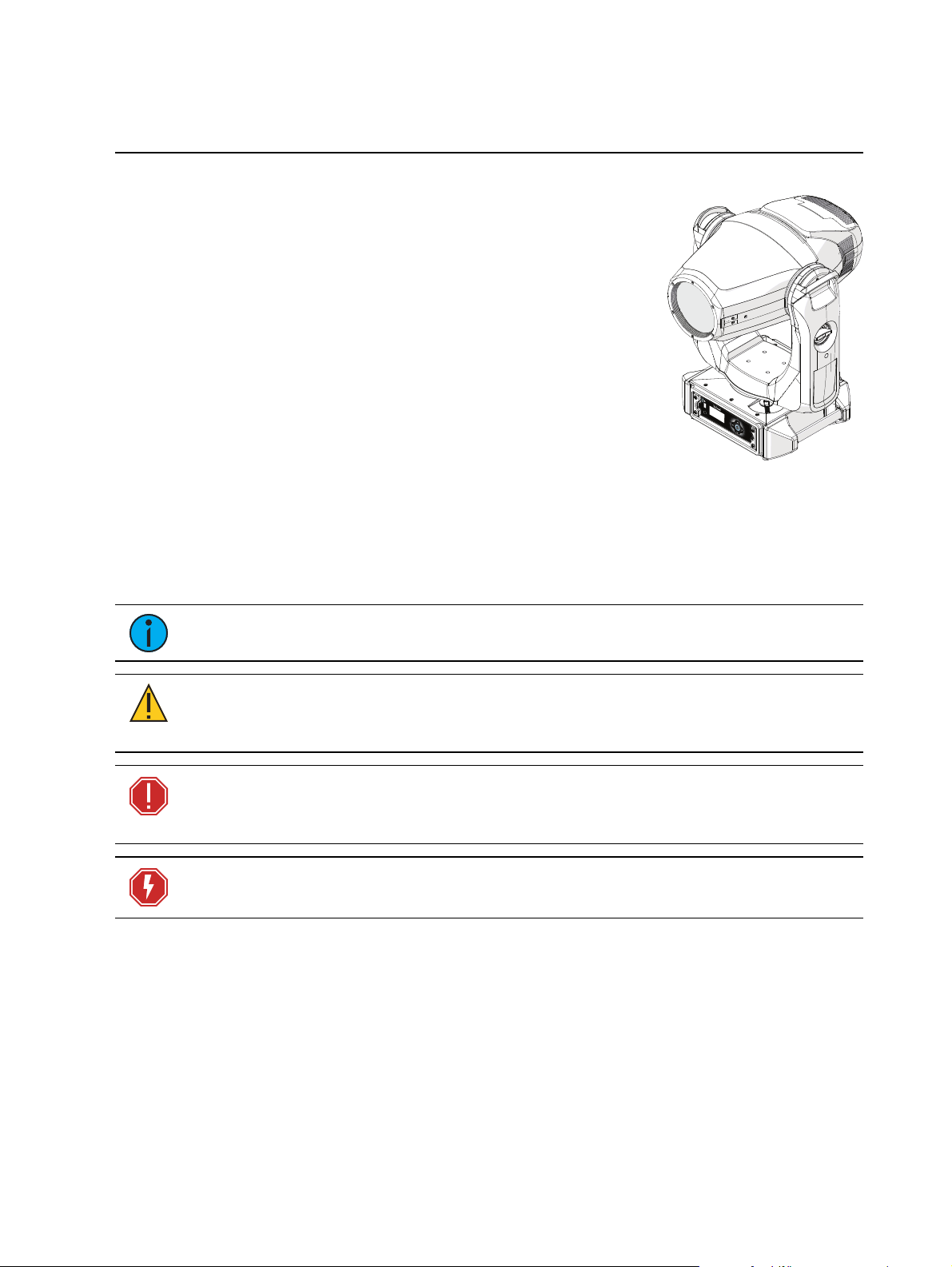
Congratulations on your purchase of the Relevé Spot automate d luminaire fromETC.
Relevé Spot is an LED-based automated spot lumina ire that
provides high-quality color control, predictable smooth pan and tilt
control, and unparalleled zoom optics.
Relevé Spot builds on the legendary color control of ETC LED
products and provides a relia ble, full-fea tured automated
luminaire of the highest quality.
About This Manual
This manual provides information required for safe installation,
operation, and scheduled ma intenance of the Relevé Spot
automated luminaire. For your safe ty, read this entire manual prior
to installing, operating, or se rvicing the Relevé Spot lumina ire.
Other References
Relevé Spot videos are availa ble for viewing from the ETC website etcconnect.com/ReleveSpot.
Document Conventions
This document uses the following conve ntions to draw your attention to important information.
Note:
CAUTION:
undefined or unwanted consequences of an action, potential for data loss or
an equipment problem.
Notes are helpful hints and informa tion that is supplemental to the main text.
A Caution statement indicates situations where there may be
WARNING: A Wa rning stateme nt indicate s situations where da mage may
occur, people may be harmed, or there are serious or dangerous
consequences of an action.
WARNING: RISK OF ELECTRIC SHOCK! This warning statement indicates
situa tions where there is a risk of electric shock.
All ETC documents are availa ble for free download from our website etcconne ct.com.
Please email comme nts a bout this manual to TechComm@etcconnect.com.
Int roduction 1
Page 8

Help fromTechnical Services
•
•
•
•
•
•
If you are having difficulties, your most convenient resources are the references given in this
user manual. To search more widely, try the ETC website at etcconnect.com or the ETC support
website at support.etcconnect.com.
If none of these resources is sufficient, contact ETC T echnical Services directly at one of the
offices ide ntified below. Emergency service is available from all ETC office s outside of normal
business hours.
When calling for help, ta ke these steps first:
Prepa re a detailed de scription of the problem
Go ne ar the equipment for troubleshooting
Find your notification number if you have called in previously
Locate the product model and serial number
Know your power source
Know your control source
Americas United Kingdom
ETC, Inc. ETC Ltd
Techn ical Services Departmen t Techn ical Services Departmen t
30 31 Pleasant View Road 26 -28 Victoria Ind ustrial Estate
Mi ddleto n, WI 5 3562 Victori a Road,
80 0-7 75-4382 (USA, toll -free) Lon don W3 6UU England
+1-608 831-411 6 +44 (0)20 8 896 1000
servi ce@etcconn ect.co m techs ervltd @ etcconnect.com
Asia Germany
ETC Asia ETC GmbH
Techn ical Services Departmen t Techn ical Services Departmen t
Ro om 1801 , 18/F Oh mstrasse 3
Tower 1, Phase 1 Enterp ris e Square 83 607 Hol zkirchen , Germany
9 Sheung Yuet Road +49 (80 24) 47 0 0-0
Kowlo on B ay, Kowlo on, Hong Kong techs erv-ho ki@ etcco nnect.com
+852 2799 1220
servi ce@etcasia.co m
France
ETC France
62 -64 rue Dani ell e
Casanova
Saint-Denis Cedex,
F93200
+33 1 424 3 353 5
techs ervltd @ etcconnect.com
2 Relevé Spot User Oper at ion s Manual
Page 9

Warranty Service
•
•
•
•
•
•
•
•
•
•
•
ET C warranty terms and conditions are available on the ETC website etcconnect.com.
Compliance
Relevé Spot has been tested to, is liste d unde r, or complies with the following regulatory
compliance and standards:
cETLus
Te sted to UL 1573 and CSA C22.2 No. 166 - Stage and Studio Luminaires with additional
compliance to UL 8750, LED luminaire
IEC 62471
LE D Risk Group 1 - the luminaire LEDs do not pose a hazard due to normal behavioral
limitations on exposure
FCC - Part 15 Class A
This device complies with Part 15 of the FCC Rules. O pe ration is subject to the following
two conditions: (1) this device may not cause ha rmful interference, and (2) this device
must accept any interference received; including interference tha t may cause undesired
operation.
Note:
This equipment has been tested and found to comply with the limits for a Class
A digital device, pursuant to Part 15 of the FCC rules. These limits are designed to
provide reasonable protection against harmful interference when the equipme nt is
operated in a commercial environment. This equipment generates, uses and can
radiate radio frequency energy and, if not installed and used in accordance with the
instructions, may cause harmful interference to radio communica tions. Operation of
this e quipment in a residential area is likely to cause harmful interference, in which
case the user will be required to correct the interference at his own expense.
CE
EN 55015:2013 + A1:2015
EN 61547:2009
EN 61000-3-2:2014
EN 61000-3-3:2008
EN 60598-2-17:1989
EN 60598-1:2015
EN 62471:2008
C-TICK
N4241
Int roduction 3
Page 10

Declaration of Conformity
EC DECLARATION OF CONFORMITY
Informational notes: The product(s) named herein have been found to comply with the testing and marking requirements of Australia and New Zealand and are suitable
for importation into those countries.
To ensure Compliance of this product with the stated Directives it must be installed and operated for its intended use according to the manufacturer’s instructions
London, United Kingdom Mr Adam Bennette
(Place of issue) (Name of authorised person)
8th Nov 2018
(Date of Issue) (Signature of authorised person)
Printed 8 November 2018
Page 1 of 1
Declaration:
Previous issue: 8th Nov 2018
Filename: master declaration 2018_2.docx
233 A
We, Electronic Theatre Controls Limited
declare under sole responsibility that the product(s):
Product name:
Relevé Automated luminaire
Product type/model:
Relevé RELSPOT
to which this declara!on relates is/are in conformity with the following Direc!ves by the applica!on of
the quoted Standards.
Low Voltage Direc!ve (LVD) 2014/35/EU:
EN 60598-1:2015 Luminaires. General requirements and tests
EN 60598-2-17:1989 Luminaires. Par!cular requirements. Specifica!on for luminaires for stage
ligh!ng, television, film and photographic studios (outside and indoor)
EN 62471:2008 Photobiological safety of lamps and lamp systems
Electromagne!c Compa!bility Direc!ve (EMCD) 2014/30/EU:
EN 55015:2013+A1:2015 Limits and methods of measurement of radio disturbance characteris!cs of
electrical ligh!ng and similar equipment
EN 61547:2009 Equipment for general ligh!ng purposes. EMC immunity requirements
EN 61000-3-2:2014 Electromagne!c compa!bility (EMC). Limits. Limits for harmonic current
emissions (equipment input current up to and including 16 A per phase)
Class A
EN 61000-3-3:2008 Electromagne!c compa!bility (EMC). Limits. Limita!on of voltage changes,
voltage fluctua!ons and flicker in public low-voltage supply systems, for
equipment with rated current <= 16 A per phase and not subject to
condi!onal connec!on
Restric!on of the Use of Certain Hazardous Substances in Electrical and Electronic Equipment Direc!ve
(RoHS2) 2011/65/EU:
These product(s) do not contain any of the following substances, or they contain trace amounts below
allowable or measureable levels in each component or mechanically separable part:
Lead (Pb), Mercury(Hg), Cadmium (Cd), Hexavalent Chromium (Cr6+),
Polybrominated Biphenyls (PBB), Polybrominated Diphenyl Ether (PBDE)
4 Relevé Spot User Oper at ion s Manual
Page 11

Safety Notices
•
•
•
•
•
•
•
Relevé Spot is a high-performance automated spot luminaire that is intended
use only
. Read the entire user manual before installing and operating this equipme nt.
for professional
READANDFOLLOWTHESE SAFETYWARNINGSBEFOREUS E:
For indoor use only. The luminaire is IP20 rated for installation in dry locations only. When
selecting the installation location, ensure the luminaire will not be exposed to extreme
cold or hea t outside of the operational range (see
Environment on page12
), moisture, or
dust.
Do not project the light beam onto combustible surfaces or materials. The minimum
distance you should maintain from the luminaire head to an illuminated surface is 2 m,
and the minimum distance from the lumina ire head to any flamma ble materials
(de corations, etc.) is 0.1 m.
The luminaire can be yoked in any mounting position, but it must be mounted and
supported only by the suspension locations provide d in the enclosure. See
Mounting Rails on pa ge 21
.
Attach Clamp
The installation location must safely hold ten times the weight of the Relevé Spot
luminaire and support its intended operation. See
Weight on page 14
.
Suspend the luminaire from a suitable structure using a minimum of two hook cla mps (not
provided) and secure d with tightene d steel bolts (12 mm (1/2 in) diameter) , washe rs, and
locking nuts.
Always use and install a suita ble safety cable as a secondary safety mea sure to pre vent
accidental da mage and/or injury in the event the installation clamps fail. T he safe ty cable
must, at a minimum, hold ten times the weight of the luminaire . ETC offers a suitable
safety cable, which is available separately. O rde r part number 7060A1022.
Disconnect the luminaire from power and DMX and allow it to cool before performing any
cleaning and maintenance procedures.
Storage and Transporting
Use care whe n transporting or storing the Relevé Spot luminaire. Use a fitted road case or reuse
the original shipping materials to safely transport or store the luminaire.
Note:
All pan and tilt locks on the Relevé Spot should be released before
transporting. See Pan and Tilt Locks on page9.
Unpacking Instructions
The luminaire is fully calibrated and tested at ETC, then carefully packaged in a shipping carton
that includes the luminaire and two clamp mounting rails.
Visually inspect the shipping carton for damage that may have occurred during transit. If the
shipping carton shows signs of damage, document the damage fully before unpacking the
luminaire. Documentation of any da mage is helpful when reporting a claim with the carrier.
The luminaire weighs approxima tely 67 lbs. (30.4 kg). For your safety, ETC recommends that
two people unpack the luminaire from the shipping carton. Use the provided handles on the
yoke arms and the enclosure to lift the luminaire from the shipping carton.
The shipping carton and pack aging materia ls ca n be valuable if you eve r need to ship the
fixture, including transporting the fixture for service. Do not discard. If you do not require this
packaging for future use, please recycle the ma terials through your local recycling program.
Int roduction 5
Page 12
Overview
•
•
•
•
•
-
-
-
-
•
•
•
•
-
•
The Relevé Spot automated luminaire fe atures:
LED Source
Features ColorSource Deep Blue array utilizing 52 Lumileds LUXEON®CLEDs in Red,
Green, Indigo, and Lime
Maximum of 6,000 field lumens at full power at any zoom position when operated within
acceptable ambient temperatures (see
33 lumens per watt
L70 rating (pe nding test results) for 35,000 hours when used at 70% output. This rating is
estimated pe nding in progress test results when operated at full within the acceptable
ambie nt tempera tures (see
Environment on page 12
Environment on page 12
)
)
Color System
Features ColorSource Deep Blue array utilizing 54 Lumileds LUXEON®CLEDs in Red,
Green, Indigo, and Lime
Additive LEDRGIL mixing system harnesses the calibrated ColorSource DeepBlue system
Brighter reds, more vibrant gree ns, and deeper blues
Even and calibrated color mixing for consistency throughout the beam
Mix infinite shades of warm and cool whites, every hue of your favorite reds and blues
Color Temperature range from 2700K - 7000K
Optical
High-quality 3:1 automated and focusable zoom range from 18 to 54 degrees
Ga te size 44 mm
Came ra flicker control:
1,200 Hz ( default) and 25,000 Hz by selection
Variable beam control creates softened gobo edge s, crisp spot edges, and provides a
morph-effect when focus is transitioned be twe en the Ani-gobo and rotating gobo wheels
6 Relevé Spot User Oper at ion s Manual
Page 13
Iris
•
•
Open
1
2
3
4
5
•
-
-
-
-
-
-
•
•
•
•
Open
1
2
3
4
5
6
•
-
-
-
-
-
-
-
•
•
•
•
Mechanical 20-blade iris provides continuous beam size control
Provides smooth timed beam control
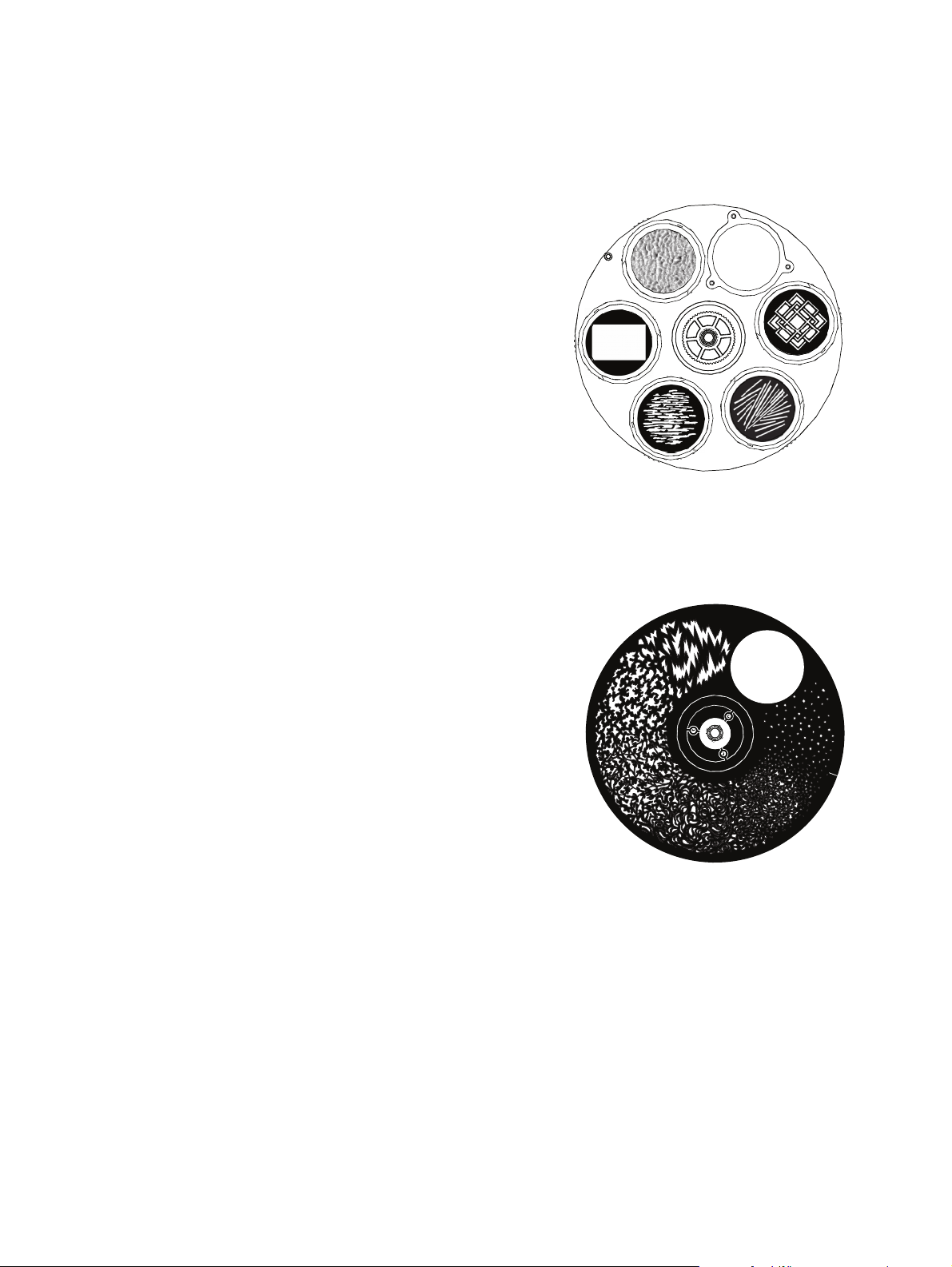
Rotating Gobos
Rotating and indexing wheel with five standard
interchangeable gobo patterns and one open
aperture:
position 0 - Open
position 1 - Ripple
position 2 - Recta ngle
position 3 - Interlocking Breakup
position 4 - Misdirection
position 5- Décor Grid
44mm image size
Unlimited clockwise and counterclockwise
rotation with variable speed
A gobo carrier kit (RELGOBOKIT / ETC pa rt
number 2510K1000) is available for purchase
from ETC for customer-insta lled gobos, and
custom gobos are ava ilable a t approved vendors. See
Relevé Spot uses the shortest path to position each pattern upon recall.
Replace a Gobo on page39
.
Ani-gobo Wheel
Custom-designed fixed-wheel with six distinct
break up patterns with interconnecting art
between patterns.
position 0 - Open
position 1 - Jagged
position 2 - Breakup
position 3 - Vines
position 4 - Swirly
position 5 - Ivy
position 6 - Dots
Pa tterns a re usable for indexed standard
break ups, animation effe cts, graphical
transitions, gobo morphing, and out-of-focus
pattern effects.
Indexes to any position on the wheel
Unlimited clockwise and counterclockwise rotation with varia ble speed, or limite d rotation
with variable speed that changes direction to avoid the open position.
Shake function with variable speed.
Ov erview 7
Page 14

Frost
•
•
Variable frost softens the beam edges smoothly and evenly.
Utilize s Rosco Quarter Ha mburg(R132) as standard. Rosco R114 and R119 are available
from ETC as field-installed accessory option kits.
Mode l Pa rt Number Description
RELFROST 114 2510K1001 Rosco R114 (Hamburg Frost)
RELFROST 119 2510K1002 Rosco R119 (Light Hamburg Frost)
RELFROST 132* 2510K1004 Rosco R132 (Q uarter Hamburg Frost)
*The luminaire ships with this frost installed.
8 Relevé Spot User Oper at ion s Manual
Page 15
Pan and Tilt Movement
•
•
•
-
•
•
•
•
•
•
540 degree pan and 270 degree tilt.
180 degree pan and tilt within 2.0 seconds.
16-bit ope ration for smooth and accura te moveme nt.
Se e
DMX Channel Mode on page37
Absolute position feedback and correction.
Menu options provide the ability to restrict pan and tilt range for use in tight spaces.
Whisper Home pan and tilt homing system provides instant and nearly motionless pan and
tilt homing.
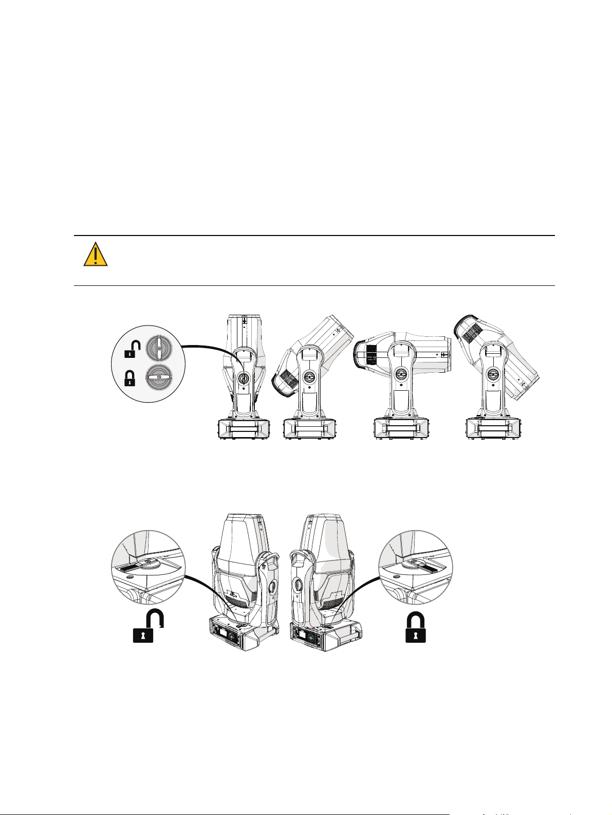
Pan and Tilt Locks
Relevé Spot features positionable pan and tilt locks for use during servicing.
.
CAUTION:
The pan and tilt locks should remain unlocked for transport.
Locks are intended only to assist while servicing the unit. Constraining
movement during transport may cause damage the Relevé Spot luminaire.
Tilt Lock
The tilt lock is available to lock the lumina ire head at its center tilt range and plus or
minus 45 and 90 degrees from the center tilt range in both directions.
Pan Lock
The pan lock is available to lock the luminaire yoke parallel to the enclosure handles and
plus or minus 90 degrees throughout the range of rotation.
Ov erview 9
Page 16
Control
•
-
DMX512-A
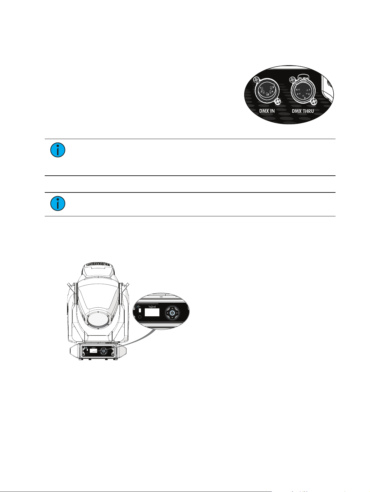
The Relevé Spot is supplied with a 5-pin XLR input connector
and a 5-pin XLR pass through connector supporting DMX.
Compliant with:
DMX512-A (ANSI E1.11-2008 (R2013)
Note:
the last fixture in the DMX line with a 120Ohm resistor or use a 5-pin male XLR DMX
terminator plug in the last luminaire's DMXThru receptacle. A 5-pin XLR DMX
terminator is an accessory option available from ETC (orde r part number SG E1507).
ET C recommends using Belden 9729 (or equivalent) cable for a reliable DMX control system.
Note:
equivalent to the specified Belden 9729.
DMX on the Relevé Spot luminaire is not self-terminating. You must termina te
Do not use microphone cable or other cable with characteristics tha t are non-
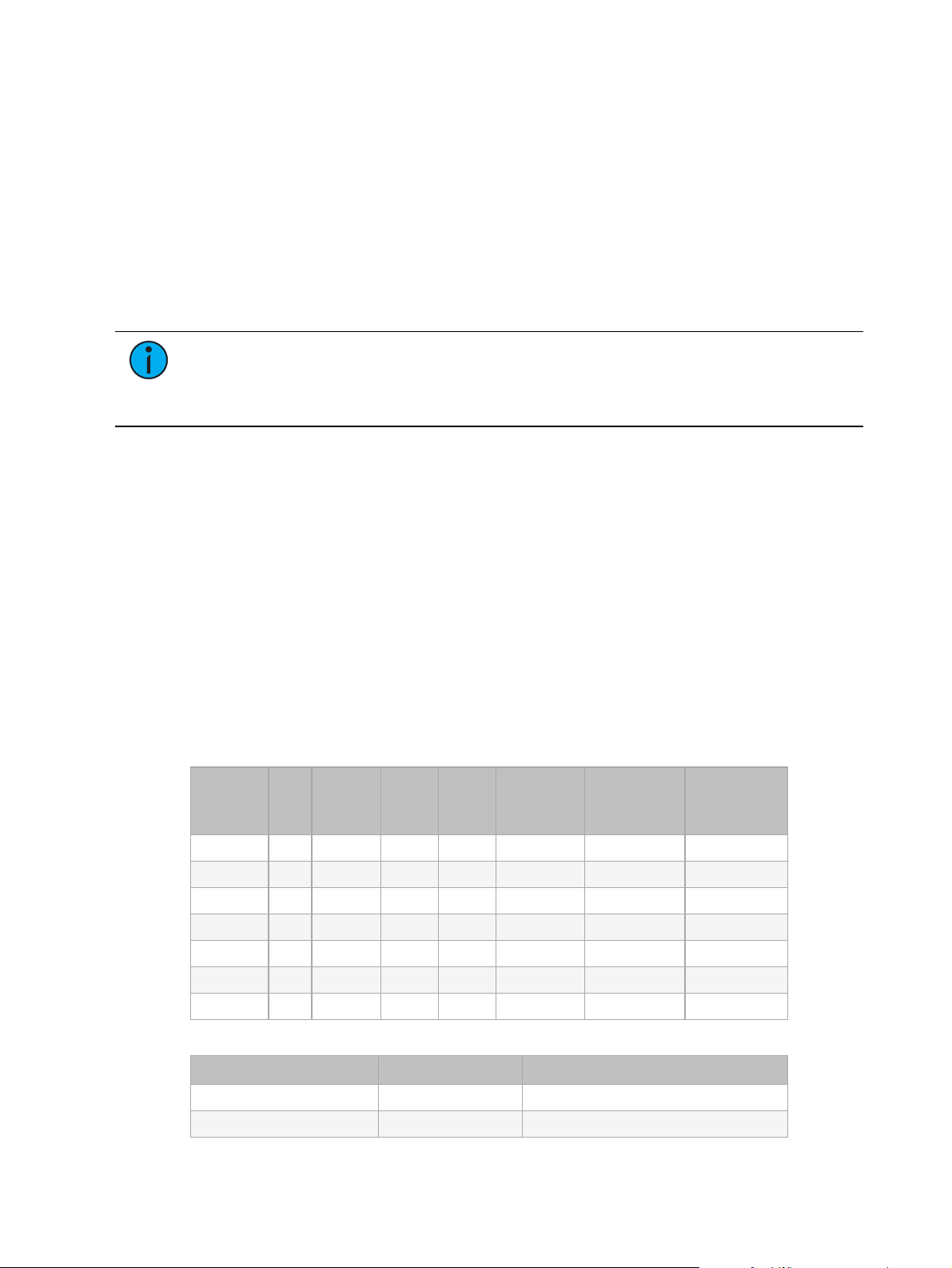
User Interface
The Relevé Spot user inte rface (UI)consists of a display and button controls for local
configuration, and a USB (type A)port for firmware update . Use the display and button controls
to configure the luminaire for your specific application and installation ne eds.
Display
The LCDis a graphic backlit display that automa tica lly adjusts its orientation 180 degrees
according to its installed orientation (floor- or truss-mounted) . While viewing the status screen,
pressing and holding the Enter o button for three seconds manually flips the display orientation
180 degrees from its current state. Button controls reorient to match the orientation of the
display. Display orientation may also be adjusted from the Options me nu (see
10 Relevé Spot User Operatio ns Manual
page 31
).
Page 17
Button Controls
•
•
•
-
•
•
-
Relevé Spot features a five-button user interface. Use the button controls to access and navigate
the onboard menu. Button controls reorient their function to match the orientation of the
display.
Auxiliary Battery
The auxiliary battery recharges over time (trick le charge) when power is applied to the
luminaire, obtaining a full charge over four hours.
The battery will remain charged for up to one year when the storage environment is within
the ambient temperature range specified for the luminaire . See
page
for details.
Environment on the next
Note:
When power is applied to the luminaire while the user interface is operating
from the auxiliary battery, the display and control will restart and the menu will return
to the status display. Any settings tha t were applied using the auxiliary battery are
saved.
Power Requirements
Input Power Voltage Range
100-240 VAC at 50/60 Hz
Relevé Spot features a universal a uto-switching power supply
Power Factor
Maximum power consumption - 285 W
Minimum power consumption - 29 W
After 15 minutes without active control, or whe n the Relevé Spot detects that the DMX
control signal is lost, standby power save mode is enable d.
Full Power Consumption
Measurements listed below are the Relevé Spot in regulated direct mode with LEDs at full and
all motors functioning.
Voltage
[V
RMS
Freq
Curre nt
]
[Hz]
[A
RMS
]
Power
[W ]
Power
[VA]
Power
Factor
[W /VA]
Crest Factor
[Vpk/V
RMS
]
Crest Factor
[Apk/A
RMS
]
100 50 2.62 259.9 272.2 0.99 1.42 1.34
100 60 2.63 260.9 264.5 0.99 1.43 1.34
120 60 2.18 262.5 264.3 0.99 1.42 1.36
200 50 1.28 253.1 258.4 0.97 1.42 1.51
208 60 1.23 251.2 252.4 0.98 1.42 1.51
220 50 1.17 255.6 261.8 0.96 1.42 1.57
240 60 1.10 252.2 270.5 0.95 1.42 1.61
Inrush
Voltage [VRMS] Freq [Hz] Maximum Inrush [Apk]
120 60 23.8
240 60 51.3
Ov erview 11
Page 18
Luminaires per Circuit (20 A)
•
•
•
•
•
•
-
-
4 luminaires a t 100 VAC
5 luminaires a t 120 VAC
10 luminaires at 240 VAC
Note:
Relevé Spot requires power from a non-dimmable source . Consult the
upstream breaker trip curve specification for compatibility information with the required
input power.
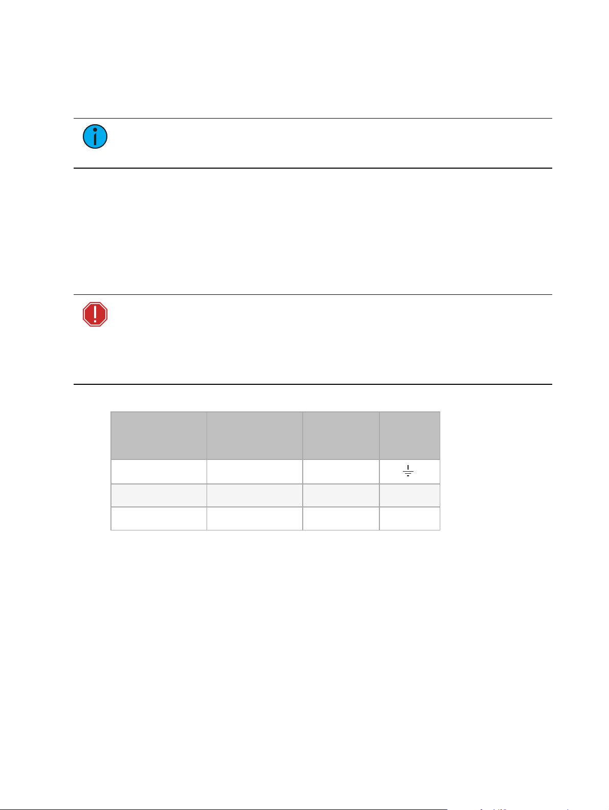
Power Receptacle/Connector Specification
Power input and power feed through conne ctions are made to powerCON®type NAC3MPA-1
and NAC3MCB-1 receptacles on the Power Module.
The luminaire ships with a 1.5 m powerCON power-input cable with a connector of choice. See
the Re levé Spot datasheet for ordering informa tion. Use only compatible power cords with
mating connectors for the specified receptacles.
Power In (blue) and Power Thru (gray) receptacle s a re keyed differently to prevent inte rmating.
WARNING: The powerCON is a connector without breaking capacity, i.e.,
the powe rCON should not be connected or disconnected under load or while
live!
AVERTISSEMENT : Le powerCON est un connecteur sans capacité de
coupure, c’est-à-dire que le powe rCON ne doit pas être connecté ou
déconnecté lorsqu’il est sous tension!
Se e the following wire color code chart:
Wire Color Code
(International
Standard)
Wire Color Code
(US Standard)
Conne ction
Type
Te rminal
Green/Ye llow Green Ea rth/ Ground
Blue White Neutral N
Brown Black Line (Live) L
Environment
The Relevé Spot luminaire opera tes in ambie nt temperatures of 0-40°C (32-104°F), and
relative humidity range 5-95%, non condensing
The Relevé Spot is IP20, ra ted for indoor use only
IP2x indicates protected aga inst intrusion by fingers or similar obje cts
IPx0 indicates no protection against liquid contact and ingress of liquid objects
12 Relevé Spot User Operatio ns Manual
Page 19
Acoustic Performance
•
•
•
•
•
•
Relevé Spot luminaire acoustic performance is dependent on the installation environment and
operational use.
Note:
Acoustic da ta has been measured in accordance with ISO 7779
(ANSIS12.10-1985).
The luminaire will not exceed 30.7 dBA at one meter distance in any direction when
the opera ting temperature is 23°C (73°F);
the luminaire is in continuous operation in a fixed position with the emitters on at full; and
the fa n is in Auto mode.
Note:
Because Relevé Spot uses absolute encoders, the homing procedures are
acoustically similar to results listed above for the fixed-position me asurements.
The luminaire will not exceed 50 dBA at one meter dista nce in any direction when
the opera ting temperature is 23°C (73°F);
the luminaire is in continuous operation with me chanical feature movement (pan/tilt,
media , zoom, iris, etc.); and
the fa n is in Auto mode.
Ov erview 13
Page 20
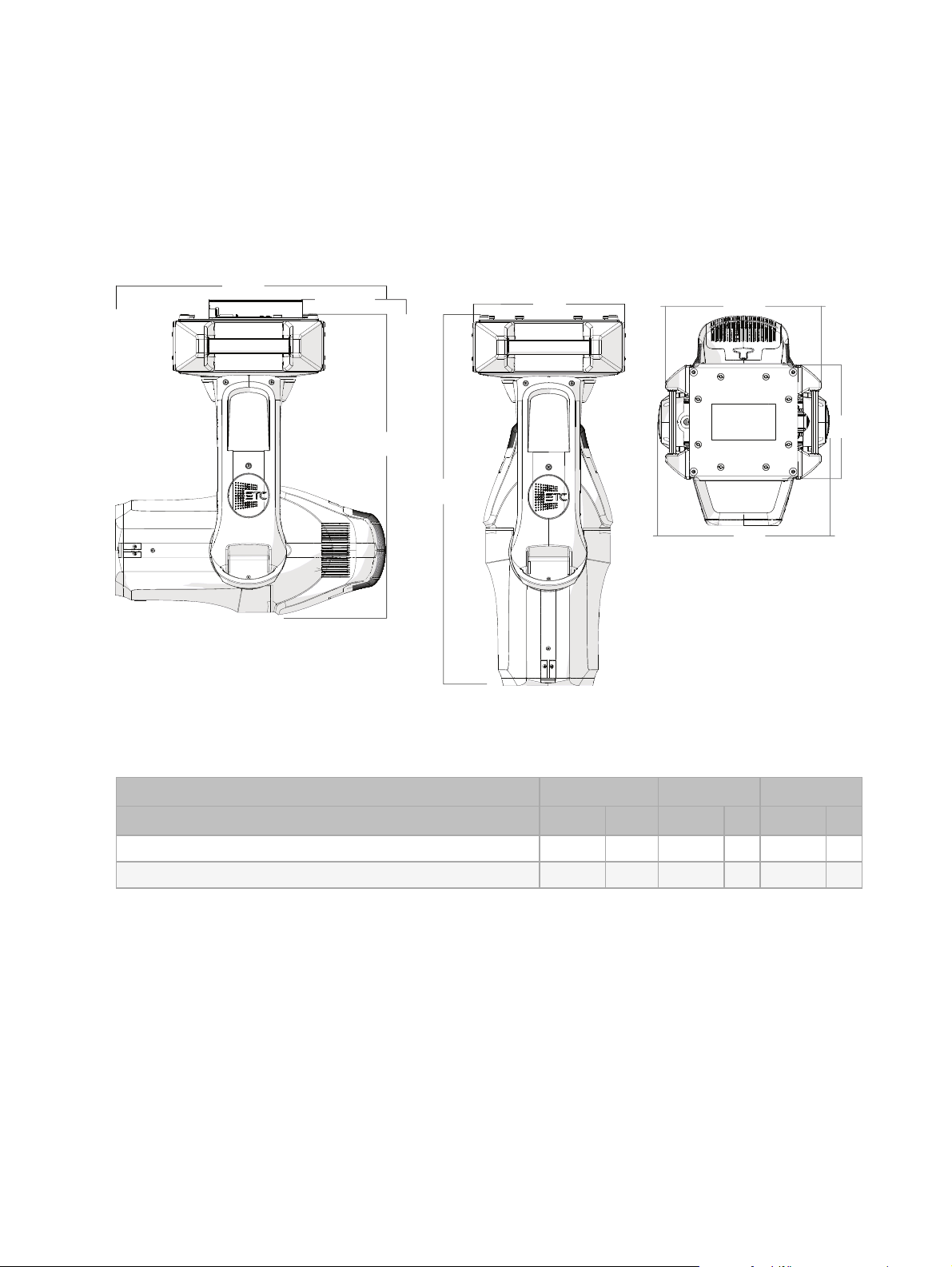
Weights and Dimensions
•
•
18
.
9 in
48
cm
13 in
33 cm
17.2 in
43.7 cm
23.2 in
58.9 cm
13 in
33 cm
25.7 in
65.3 cm
31.6 in
80.3 cm
1.7 in 4.3 cm
Weight
The Relevé Spot weighs 67.5 lbs. (30.6 kg)
Dimensions
The Relevé Spot rotates within a 24.4in (62cm) circular diameter (base luminaire ,
excluding any accessories).
Item Description Height Width Depth
inches cm inche s cm inches cm
Relevé Spot without clamp mounting rails 31.6 80.3 18.9 48 13.0 33
Relevé Spot with clamp mounting rails 33.3 84.5 18.9 48 13.0 33
14 Relevé Spot User Operatio ns Manual
Page 21

Mounting
10 in
25.4 cm
1
A B
5 in
12.7 cm
For installation convenience, four hanging points are provided on the enclosure, two each in
planes 90 degrees from each other. See
installation instructions.
Item# Na me Pa rt Number Notes
Attach Clamp Mounting Rails on page21
for
Clamp
1
Mounting
2510A2017
Rails
Se curely install on the provided attachment
points on the base of the enclosure.
Relevé Spot can be yoked in any mounting position using the provided hanging points.
Alternatively, the Relevé Spot luminaire can be floor-mounted (placed enclosure -side down on a
stage floor).
Truss mounting clamps are available from ETC, sold separately.
Pa rt Number Description
PS F1131 Mega-Coupler™ Clamp 1.9" Pipe/2.0"Truss, Black
PS F1132 Mega-Coupler Cla mp 1.9" Pipe/2. 0" Truss, W hite
PS F1133 Mega-Claw™ Clamp 1.9" Pipe/2.0"Truss, Black
PS F1134 Mega-Claw Clamp 1.9" Pipe/2.0"Truss, White
PS F1135 Trigger Clamp™ 1.9" Pipe/2.0" Truss Tube, Black
PS F1136 Trigger Clamp 1.9" Pipe/2.0"Truss Tube, White
Ov erview 15
Page 22

Safety
•
•
•
•
•
•
Note:
The installation location and structure must comply with local codes and be
certified by the authority having jurisdiction (AHJ).
The Relevé Spot luminaire is intended for professional use only on stages, in
theaters, or other professional installations.
For indoor use only. When se lecting the installation location, ensure the luminaire
will not be exposed to extreme cold or heat outside of the operational range (see
Environment on page12), moisture, or dust.
Do not project the light beam onto combustible surfaces or materials. Minimum
distance to illuminated surface 2 m, and a minimum dista nce from the luminaire
head to combustible mate rials 0.1 m away from any flammable materials
(decoration, etc.).
Suspend the luminaire from a suitable structure using a minimum of two hook
clamps (not provided) and se cured with tightened ste el bolts (12 mm (1/2 in)
diameter), washe rs, and lock ing nuts.
Always use and install a suitable safety cable as a secondary sa fety measure to
prevent accidental damage and/or injury in the event the installation clamps fail.
The safe ty cable must, at a minimum, hold ten times the weight of the lumina ire.
ET C offers a suitable safety cable which is availa ble separately, order part
number 7060A1022.
The installation location and safety cable must, at a minimum, safely hold ten
times the weight of the Relevé Spot luminaire and support its intended opera tion.
Se e Weight on page 14.
16 Relevé Spot User Operatio ns Manual
Page 23
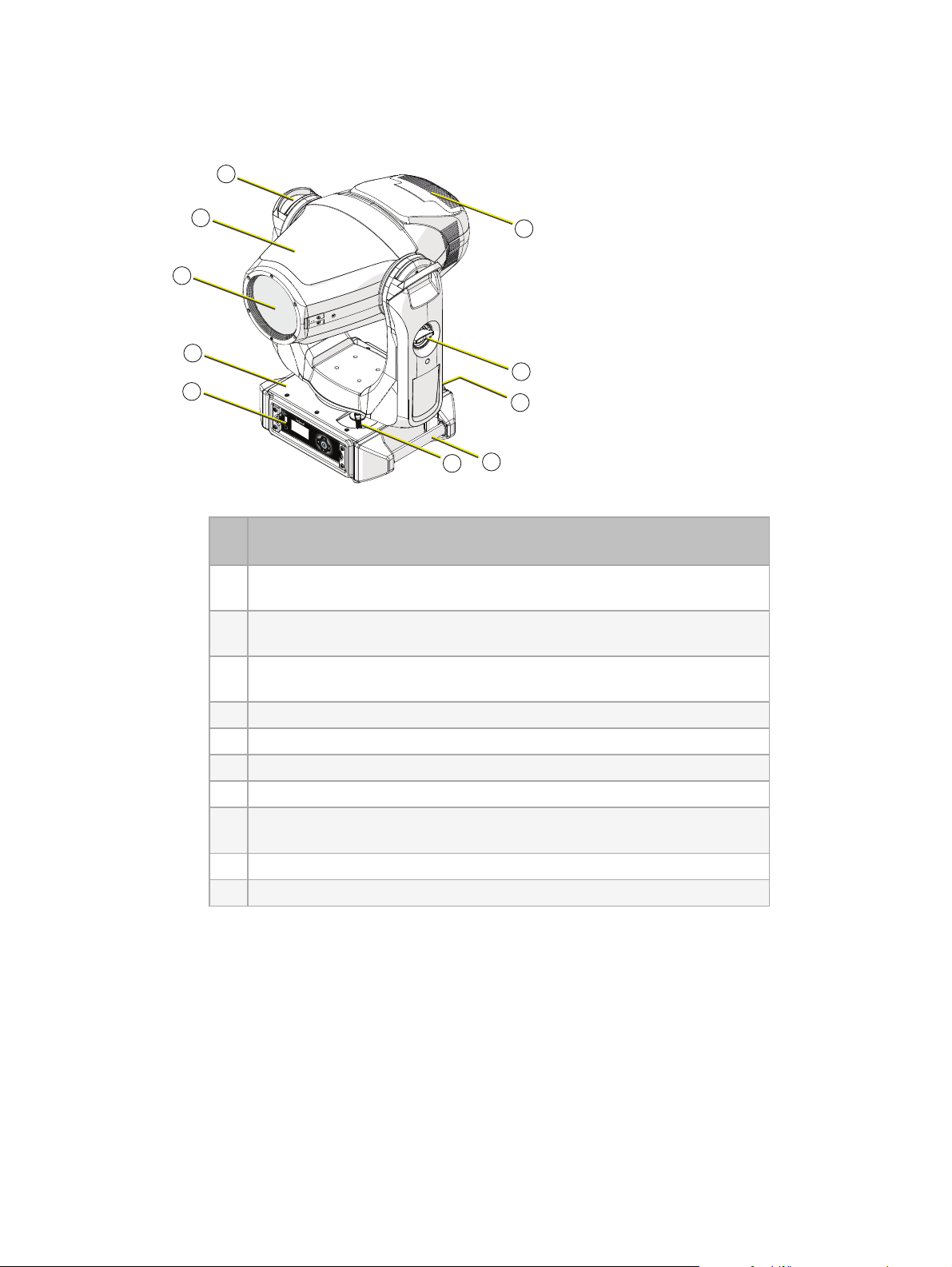
Luminaire Overview
1
2
3
4
5
6
7
8
9
10
Top Level
Item
#
LED Module - includes the LED array and driver board, re flector, and
1
fan assembly
Yoke Assembly - includes yoke handles, supporting motor control
2
boards, pan motor, and tilt motor
Head - include s the OpticsModule, Effects Module, and supporting
3
motor control boards
Description
4 Front lens
5 Enclosure - includes pan tube and power distribution board
6 Main Control Module - includes a display, user interface , and US B port
7 Tilt lock
Power Module - includes recepta cle s for DMX In, DMX Thru, Powe r In,
8
and Powe r Thru
9 Enclosure handle
10 Pan lock
Ov erview 17
Page 24
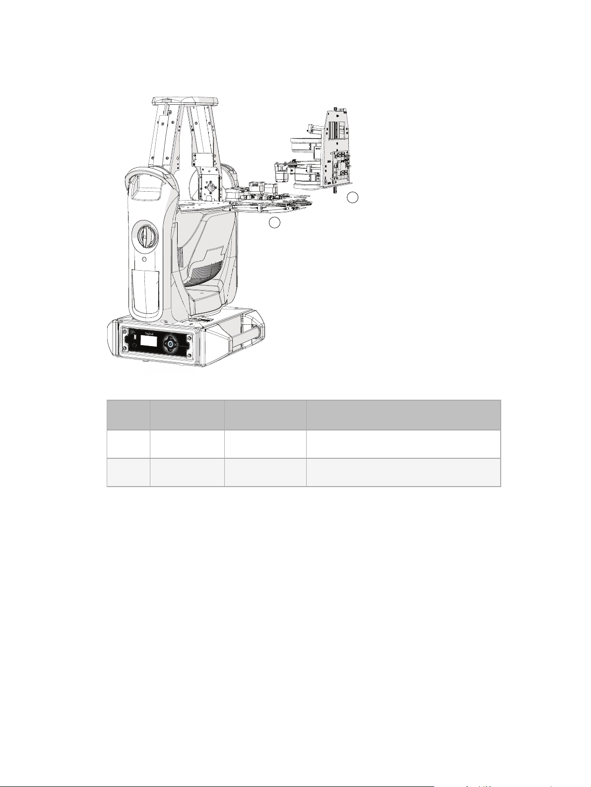
Sub Assemblies
1
2
Head
Item# Name
1 Effects Module 2510A2009-CFG
2 Optics Module 2510A2008-CFG
Replacement
Pa rt Number
Notes
Rotating Gobo Wheel, Ani-gobo Wheel,
Iris assembly
Focus and zoom lens assembly, and Frost
assembly
18 Relevé Spot User Operatio ns Manual
Page 25
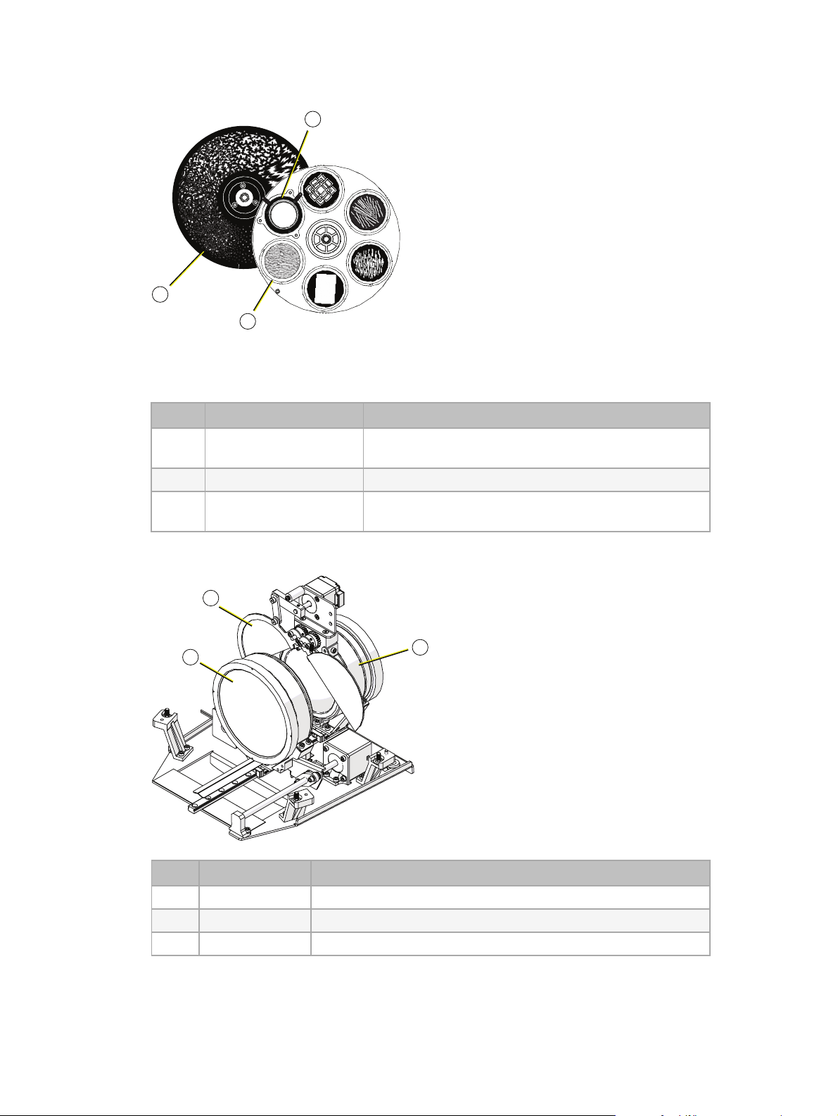
Effects Module
2
1
3
2
1
3
The image above depicts the effe cts module with the enclosure, motors, and motor control
board hidden for clarity of the internal features.
Item# Description Notes
1 Ani-gobo Wheel
Fixed gobo wheel with six breakup patterns plus an
open aperture
2 Iris assembly Smooth, stepless iris function
3 Rotating Gobo Wheel
Rotating and indexing wheel with five pa tte rns plus
an ope n aperture
Optics Module
Item# Name Notes
1 Focus lens
2 Zoom lens 18-54 degree zoom
3 Frost assembly Rosco QuarterHa mburg Frost (R132) installed standard
Ov erview 19
Page 26
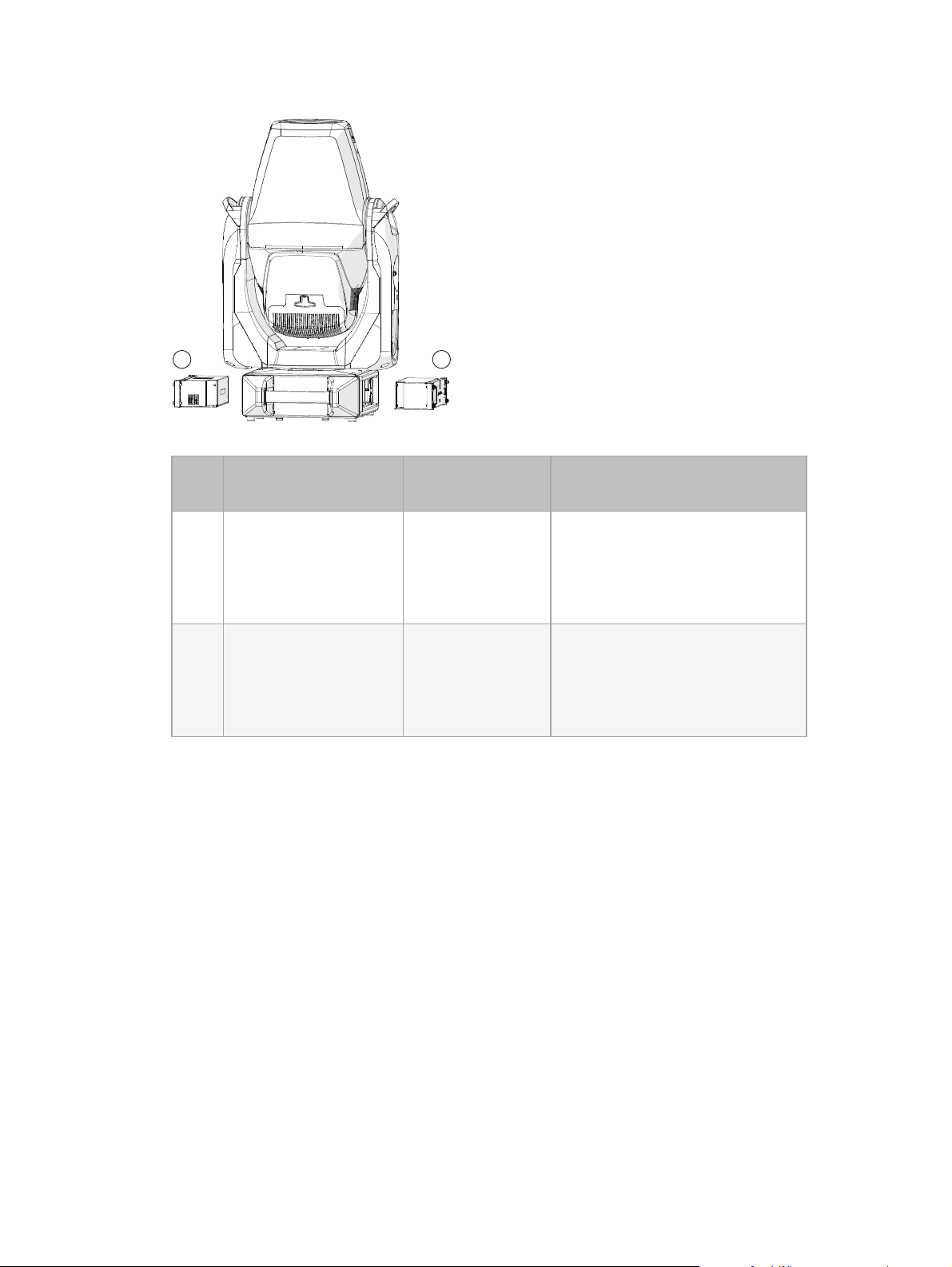
Enclosure
1
2
Item# Description
Replacement
Pa rtNumber
1 Power Module 2510A2027-CFG
2 Main Control Module 2510A2034-CFG
Notes
Power Input and Thru receptacles a nd DMXIn and Thru XLR
receptacles. Installs opposite of
the Main Control Module in the
enclosure.
User interface with display a nd
menu navigation buttons, and
USB port for firmware update.
Installs opposite of the Power
Module in the enclosure.
20 Relevé Spot User Operatio ns Manual
Page 27

Installation
10 in
25.4 cm
1
A B
5 in
12.7 cm
Attach Clamp Mounting Rails
For installation convenience, four hanging points are provided on the enclosure, two each in
planes 90 degrees from each other.
Item# Name Part Number Notes
1 Clamp Mounting Rails 2510A2017
CAUTION:
Risk of Personal Injury! Overhead mounting requires extensive
Se curely install on the provided attachment points on the ba se of the enclosure.
experience, including amongst others, calculating the working load limit
(WLL) of the truss system, a specialized knowledge of the installation material
being used, and a periodic safety inspection of all installation materials and
the luminaire. Improper installation can result in bodily injury. This luminaire
must be installed by qualified personnel only.
ATTENTION :
Risque de Blessures Corporelles ! L’installation en hauteur
nécessite une vaste expérience, qui inclut notamment le calcul de la charge
nominale du système de pont, une connaissance spécialisée du matériel utilisé
pour l’installation et l’inspection régulière de tout l’équipement de
l’installation et du luminaire. Une installation incorrecte peut entraîner des
blessures corporelles. Ce luminaire doit uniquement être installé par du
personnel qualifié.
Two clamp mounting rails are provided with the Relevé Spot luminaire for
attachme nt to truss clamps (not provide d) or other compatible hardware for
installation.
1. Install the truss clamps (not provided) to the clamp mounting rails.
The clamp mounting rails fea ture a safe-latching system for secure fit to the
hanging points on the enclosure.
Inst allat ion 21
Page 28

2a 2b 2c
2. Attach the clamp mounting rails to the enclosure.
24.4 in
62 cm
a. Align the keyed hole s of the clamp mounting rail to the attachment points on the
enclosure.
b. Each clamp mounting rail should be installed on the same plane and facing the same
direction.
c. Slide the clamp mounting rail in place until the lock ing mechanism is seate d and
captures the attachment point. The mounting rail will be locked in place and flush to
the enclosure when installed properly.
Spacing Requirements
For full pan and tilt operation, install the Relevé Spot with a minimum of 24.4 in (62cm)
between centers. The luminaire features Whisper Home te chnology, which provides instant pan
and tilt homing at power on with minima l movement. You can install the luminaires closer
together if you restrict the pa n and/or tilt movement using the features provided for pan and tilt
in the Options menu.
Note:
top hat. Re fer to the accessory datashee t for dimensions.
Add additional spacing between luminaire s when using accessories such as a
Floor Mounting
Relevé Spot can be installed on the floor or a suita ble level, horizontal, a nd flat surface . Rubber
feet are provided on the base of the enclosure.
22 Relevé Spot User Operatio ns Manual
Page 29

Rigging
Push
1
2
3
4
5
1
2
3
4
5
WARNING: RISKOF INJURY! Check ea ch clamp mounting rail and truss
clamp for prope r and secure installation before hanging the luminaire.
AVERTISSEMENT : DANGER DE BLE SSURE ! Avant d’a ccrocher le
luminaire, vé rifiez chaque croche t et chaque porte use pour une installation
correcte et en sécurité.
1. Lift the luminaire to the installation location. We recommend that two people lift the
luminaire.
2. Secure the luminaire in place using the previously installed truss clamps or other
installation hardware. Secure the attachment hardware in pla ce by tightening the
hardware (wing bolt or other hardware), ensuring the luminaire is securely installed and
supported to the truss.
Note:
The installation must follow local codes and standard practices for overhead
rigging. When the luminaire is mounte d in an overhead rigged position, you must also
secure it in place using a safety cable that ca n hold at least ten times the weight of the
luminaire. A suitable safety cable is available from ETC (part number 7060A1022).
Conta ct ETC for additional details.
3. Attach a safety cable to the lumina ire.
a. Loop one end of the safe ty cable around the enclosure handle a nd attach the clip
onto the cable .
b. Loop the other end of the cable around the truss or pipe structure, then secure the clip
onto the cable .
Connect Data and Power
Connect DMX-512
ET C recommends Be lden 9729 or equivalent 2-pole twiste d, shielded wire. The connectors must
be XLR 5-pin female (DMX IN) and XLR 5-pin male (DMX THRU). Following best pra ctices for
DMX, a maximum of 32 DMXdevice s may be connected in any one DMX data run when
installed in a daisy-chain fashion. See
cable specifications.
XLR Pinout
ET C recommends using the following standard pinout when preparing DMX cable (Belden 9729
or equivalent)with an XLR conne ctor. The second data pair in the re commended cable type is
not used by the Relevé Spot luminaire and should be capped off and tied ba ck for future service.
DMX512-A on page10
for details on DMX connector and
DMX-512 Pinout for 5-pin XLR (EIA-485)
DMX Thru Receptacle Pin # Use DMX Input Receptacle
1 Common (shield)
2 Data - (typically black wire)
3 Data + (typically white wire)
*X LR p ins viewed fr om t he
outside
Inst allat ion 23
4 unused
5 unused
*X LR p ins viewed fr om t he
outside
Page 30

Connect DMX
POWER IN POWER THRU
1. Connect the prepared DMX cable with the 5-pin XLRconnector from the console or routed
lighting network to the luminaire DMXInput receptacle.
2. If required, connect the prepared DMXca ble with the 5-pin XLR connector from the
DMXThru connector on the luminaire to the next device in the control run.
3. Dress all cables so they will not interfere with the luminaire moveme nts during normal
operation.
Terminate DMX-512
The last luminaire in the DMX control run must be te rminated to preve nt signal re flections.
Signal reflections cause noise on the data line, re sulting in corrupted data betwee n the control
source and the luminaire. Use a DMXtermination plug 5-pin XLR male (ava ila ble from ETC;
order part number SG E1507).
Connect Power In and Thru
Note:
Relevé Spot requires standard ACpower from 100-240 VAC at 50/60 Hz. See
Requirements on page11
for the specified powerCON rece pta cle s. See
page12
Installation must follow all national and local codes for electrical e quipment.
Power
for details. Use only compatible power cords with mating connectors
Power Receptacle/Connector Specification on
for details.
WARNING: The powerCON is a connector without breaking capacity, i.e.,
the powe rCON should not be connected or disconnected under load or while
live!
AVERTISSEMENT : Le powerCON est un connecteur sans capacité de
coupure, c’est-à-dire que le powe rCON ne doit pas être connecté ou
déconnecté lorsqu’il est sous tension!
1. Connect the prepared compatible cable with
conne ctor to the P ower In receptacle.
2. If you are continuing the powe r to the next luminaire ,
conne ct a pre pared compatible cable with connector
to the Power Thru receptacle.
3. Plug the power cord into the powe r source.
4. Dress all cables so they will not interfere with the
luminaire movements during normal operation.
24 Relevé Spot User Operatio ns Manual
Page 31

Power Up
•
•
•
•
Direct Mode (25)
Wired DMX
001
v #.#.#
Prior to applying power to the luminaire, check the installation and ensure the following:
The luminaire is mounted securely and the safety ca ble is properly secured to a suitable
structure.
The pan and tilt locking mechanisms are unlock ed, allowing unrestricted movement of the
luminaire head and yoke.
All luminaire covers are fastened securely, and any luminaire accessory is tethered to the
luminaire using the appropriate safety tether.
There are no obstacle s that prevent free movement of the luminaire head and yoke,
including the dressing of all power and data cables.
Apply power to the circuit. The displa y will power on and the luminaire will begin its homing
proce dure . Reference
status screen displays the luminaire DMXaddress, DMXcontrol mode, and firmware version
number.
Homing
Homing below
for details. W hen the homing procedure is complete, the
When you apply power to the lumina ire, the display will power on and the luminaire will begin
the process of testing its inte rnal features, including achieving the calibrated pan and tilt
position using Whisper Home te chnology. All internal features of the luminaire simultaneously
locate the ir home position and await a control signa l. All features except for the frost and iris
home sile ntly. Pan and tilt will respond to any received control value within 27 seconds after
power up. The luminaire will not illuminate the LEDs until the entire homing process completes.
If the luminaire eithe r loses its DMXcontrol signal or never receives a signa l after a period of
27seconds, the luminaire will either hold at its current state until a signal is receive d (the
default setting for DMXloss behavior) or Wait and Fade according to its configured fade time.
The DMXaddress on the status screen will flash, indicating that no DMXcontrol signa l is
present.
Inst allat ion 25
Page 32

User Interface
•
•
The Relevé Spot user inte rface (UI)consists of a display and button controls for local
configuration, and a USB (type A)port for firmware update . Use the display and button controls
to configure the luminaire for your specific application and installation ne eds.
Auxiliary Battery
The auxiliary battery recharges over time (trick le charge) when power is applied to the
luminaire, obtaining a full charge over four hours.
The battery will remain charged for up to one year when the storage environment is within
the ambient temperature range specified for the luminaire . See
for details.
Environment on page12
Note:
from the auxiliary battery, the display and control will restart and the menu will return
to the status display. Any settings tha t were applied using the auxiliary battery are
saved.
When power is applied to the luminaire while the user interface is operating
Display
The LCDis a graphic backlit display that automa tica lly adjusts its orientation 180 degrees
according to its installed orientation (floor- or truss-mounted) . While viewing the status screen,
pressing and holding the Enter o button for three seconds manually flips the display orientation
180 degrees from its current state. Button controls reorient to match the orientation of the
display. Display orientation may also be adjusted from the Options me nu (see
page 31
).
Button Controls
Relevé Spot features a five-button user interface. Use the button controls to access and navigate
the onboard menu. Button controls reorient their function to match the orientation of the
display.
26 Relevé Spot User Operatio ns Manual
Page 33

Menu Navigation
•
•
Use the button controls to access and navigate the menu on the display.
<
Na viga te left - Navigates within a value selection or cancels the current operation and returns to
the previous scree n. Multiple pre sses of the back button will eventually return you to the status
display.
>
Na viga te right - Navigates the selection to the right within a menu setting.
This button features an additional shortcut function:
Pressing this button while the status screen is displa yed is a shortcut to the DMX Address
menu.
o
Enter - When the Relevé Spot luminaire is disconnected from power, pressing Enter o activates
the menu for configuration and firmwa re update using the onboard auxiliary battery. See
Auxiliary Battery on the previous page
for more information regarding the battery features.
Pressing Ente r o while na viga ting the menu activates the menu selection or store s a value. For
many settings in the menu, press the button repeatedly to navigate through the available
options while a setting is highlighted, the n press the navigate up ˄ or down ˅ button to reach
the de sired va lue.
This button features a shortcut function:
Pressing and holding this button for three se conds manually flips the display orientation
180 degrees. Button controls reorient to match the orientation of the display. This shortcut
setting does not persist after a power cycle.
User Int er face 27
Page 34

Λ
Na viga te up - Increases a value or menu selection by one. Press and hold the button to increa se
the ra te of change.
V
Na viga te down - Decrea ses a value or menu selection by one. Press and hold the button to
increase the rate of change.
Status Screen
When the Relevé Spot is powered up initially, the luminaire runs self tests to check the status of
the fe atures of the luminaire and performs a homing routine. The user interface display shows
the current DMXaddress, DMX mode, and installed version of firmware. The DMXaddre ss will
flash whe n no DMX is present.
Note:
luminaire. Relevé Spot firmware is available for download from the ETC website
etcconnect. com/ReleveSpot. See Update Firmware with USB Drive on page35 for
instructions about updating firmware.
The menu and display are set by default to sleep after five se conds of inactivity. Press any button
to wak e the displa y. Any a dditional button press activates the menu.
ET C recommends running the most current version of firmware in your
28 Relevé Spot User Operatio ns Manual
Page 35

Menu System
Main Menu
Control Settings >
Options >
Home / Test >
Diagnostics >
Update Firmware >
Advanced >
Advanced
Control Settings
DMX Address 1
Channel Mode Standard
Data Loss Hold
Home / Test
Re-home Fixture >
Fixture Test >
Lens Cleaning Access >
Diagnostics
DMX Monitor >
Board Firmware >
Password Protected
Please Enter Access
Code below:
Options Men u
Pan/Tilt >
LED Output Freq 1200
Display >
Reset Defaults >
Update Firmwar e
USB >
Push Firmware >
•
•
•
•
•
•
Navigate the Main Menu to familiarize yourself with the onboard fea ture s available to you.
Refere nce:
Menu Syst em 29
Control Settings on the next page
Options Menu on pa ge31
Home/Test on pa ge33
Diagnostics on page34
Update Firmware on page35
Advance d on page36
- The Advanced
Menu is password protected and
reserved for trained and authorized
technicians only.
Page 36

Control Settings
Control Settings
DMX Address 1
Channel Mode Direct
Data Loss Hold
•
•
-
-
•
-
-
DM X Address - Displays the current DMX512 address. Press Enter o to edit the address.
Default Address is 001. Accepts values 1 - 488.
Channe l Mode - Displays the current DMX Cha nne l Mode. Press Enter o to edit the
mode. Default mode is Standard. Options include:
Direct
- requires 25 channels of control
Standard
Da ta Loss - Displays the current data loss setting. Press Enter o to edit the setting. Defa ult
setting is Hold (Hold Last Look).
Hold
control signal is restored. The last look will not be restored after power has been cycled.
Wait and Fade
(settable from 0 to 240 seconds) then fades intensity only.
Defaults
Menu Selection DefaultValue
- requires 20 channels of control.
- After data is lost, the luminaire maintains its last look until power is removed or
- After data is lost, the luminaire waits a specifie d period of time
DMXAddress 001
Channel Mode Standard
Data Loss Hold
30 Relevé Spot User Operatio ns Manual
Page 37

Options Menu
Options Men u
Pan/Tilt >
LED Output Freq 1200
Display >
Reset Defaults >
•
•
•
-
-
-
-
-
•
Pan/Tilt
Displays current pan and tilt settings. Navigate to and press Enter o to edit a se tting.
Tilt Invert - Inverts tilt movement. Settable to Off (de fault) or On.
Pan Invert - Inverts pan movement. Settable to Off (default) or O n.
Restricted P/T - Restricts pan and/or tilt movement to a user defined range . Settable to Off
(de fault) or On. When On is se lected, additional menu options display for selection.
Navigate to the limit you want to set and press Enter o to select. The selection will
change to the "Off" value. Press the navigate up ˄ button to increase the value one
degree. The luminaire will display and react (live ) with each increment or decre ment of
the limit value. Press Enter o to set the value. Press the navigate left < button to exit
the menu.
Pa n Limits: Min
Pa n Limits: Max
Tilt Limits: Min
Tilt Limits:Max
- Settings are Off (default) or any value between 0 and 540 degrees.
- Settings are Off (default) or any value between 0 and 540 degrees.
- Settings are Off (default) or any value between 0 and 270 degrees.
- Settings are Off (default) or any value between 0 and 270 degrees.
P/T Feedba ck - Settings are On (default) and Off. W he n On, provides pan/tilt correction
based on the encoder position. Any manual movement will be automatically correcte d to
the current encoder value. When power is cycle d to the luminaire, this setting rese ts to
On.
LED Output Freq
The LEDOutput Freq menu provides selection of the output freque ncy in Hz at which the
LEDarray pulses, or blinks, as a function of the Pulse Width Modulation (PWM). This fre que ncy
is adjustable in order to avoid visible flicker on video and film. Available options are 1200
(de fault) or 25000. For high speed exposure or rolling shutte r cameras, use the high 25000
setting. This will incre ase the PWMto 25,000 Hz and will re sult in flicker-free operation in most
circumstances.
To access the high (25000) setting, navigate to LEDOutput Freq in the Options Menu and press
Enter o to edit. Press the navigate up ˄ button to change the selection from its default 1200 Hz
to the 25000 Hz setting, and press Enter o. Changing the freque ncy from the defa ult value
(1200) can have a slight impact on the smoothness, or color-mix consistency, or both when
dimming.
Menu Syst em 31
Page 38

Display
•
-
-
•
Provides display orientation and backlight settings.
Orienta tion - Settings are Auto (default) and Flip. Navigate to Orientation and press Enter
o to edit the current setting. Press the navigate up ˄ or down ˅ buttons to change the
selection, then press Enter o to set the ne w selection.
Auto
- Detects orientation of the luminaire and automatically orients the display for best
reada bility.
Flip
- Reorients the display 180 degrees from its current setting.
Backlight - Se ttings are Off, 1 second, 5 seconds, and 30 seconds (default).
Reset Defaults
The Re set Defa ults menu resets only the options tha t are set in the Options Menu to factory
defaults.
Note:
DMXsettings are not affected when you reset the luminaire to its factory
defaults.
The following options will reset to their factory defaults:
Se tting DefaultVa lue
Tilt Invert Off
Pa n Invert Off
Pa n Limits:Min Off
Pa n Limits: Max Off
Tilt Limits: Min Off
Tilt Limits:Max Off
LED O utput Freq 1200
Display Orientation Auto
Backlight 30 seconds
32 Relevé Spot User Operatio ns Manual
Page 39

Home/Test
Home / Test
Re-home Fixture >
Fixture Test >
Lens Cleaning Access >
•
-
•
-
•
-
•
-
•
-
•
-
Re-home Fixture
Se lecting and confirming this menu option re-homes all features except for pan and tilt.
Fixture Test
This menu provides options to test all features of the luminaire in one se que nce, individual
features of the luminaire as stand-alone tests, or individual features of the lumina ire
concurrently.
All me nu options in Fixture Test are Off by default.
Note:
Ea ch test will repeat its sequence until you exit the Fixture Te st menu or select
the test option again. Multiple tests can run at the same time with the exception of All
Te st, which can only be run alone. "Running" is appended to the test name as a visual
indica tion of the current running tests.
All Test - All features of the luminaire are tested to their extents sequentia lly.
Te sts run as follows:Pan/ T ilt > Color > Gobo > Frost/Iris > Z oom/Focus > and then the
sequence repeats.
Color - All LEDs are tested to their extents.
Te st run as follows: Red LED @ 100, Red LE D @ 0, Green LED @100, Green LED @ 0,
Indigo LED@100, Indigo LED @ 0, Lime LED @ 100, and Lime LED @ 0.
Gobo - All gobos, both from the rotating gobo wheel and the ani-gobo wheel, are tested
to their extents.
Te st runs as follows:Rotating Gobo wheel snaps be twe en gobo 1, gobo 2, gobo 3, gobo
4, and gobo 5 > gobo 3 rotates counter-clockwise fast > gobo 3 rotates clockwise fast >
returns to open position > the ani-gobo wheel rotates clockwise at half spee d > counterclockwise at fast speed > returns to the open position.
Frost/Iris - The frost and iris are tested to their extents.
Te st runs as follows: Frost from full open to full closed in three seconds > full closed to
full open in three seconds > full ope n to full closed in zero seconds > wa its one second >
closed to full open in zero seconds > waits one second > Iris pulses medium spe ed for
three seconds.
Menu Syst em 33
Zoom/Focus - The zoom and focus lenses are tested to their exte nts.
Te st runs as follows: Zoom and focus lenses move from 0% to 100% > then from 100%
to 0%.
Pan/Tilt - Pan and tilt are tested to their extents.
Te st runs as follows: Pan and tilt @ 0% > pa n @ 100% > pan @ 0% > Pan @ 100% >
pan@0% > tilt @ 100% > tilt @ 0% > tilt @ 100% > tilt @ 0% > pan @ 50% > tilt @
25%.
Page 40

Lens Cleaning Access
Diagnostics
DMX Monitor >
Board Firmware >
DMX Monitor
Tilt Fine 0
Gobo Mode 0
Gobo Rot / Ind 0
Gobo R/I Fine 0
Fixed Gob Mod 0
Fixed Gob Ind 0
Focus Course 0
Focus Fine 0
Zoom 0
Iris 0
Frost 0
Configuration 0
PT Speed 0
Focus Speed 0
Color Speed 0
Beam Speed 0
DMX Monitor
Gobo Mode 0
Gobo Rot / Ind 0
Gobo R/I Fine 0
Fixed Gob Mod 0
Fixed Gob Ind 0
Focus Course 0
Focus Fine 0
Zoom 0
Iris 0
Frost 0
Configuration 0
Board Firmwar e
Bundle: #.#.#.##
CPU: #.#.#.##
LED: #.#.#.##
GUI: #.#.#.##
Pan/Tilt: #.#.#.##
Effects: #.#.#.##
Optics: #.#.#.##
The Lens Cle aning Acce ss menu provides manual control access to move the lense s for optima l
cleaning access. See
Clean the Lenses on page48
.
Diagnostics
DMX Monitor
The DMXMonitor me nu displays the value of every channel in the current selected
DMXProfile.
Direct Mode Standard Mode
34 Relevé Spot User Operatio ns Manual
This information is re ad only information and will update control values when the DMXinput
values change .
Note:
When DMX control is not present to the luminaire , "No DMXData" displays in
the DMXMonitor.
Board Firmware
The Board Firmware menu displays version information (read only) for all insta lled firmware on
the Re levé Spot.
Page 41

Update Firmware
Update Firmwar e
USB >
Push Firmware >
•
•
•
To update firmwa re on the Relevé Spot luminaire, you must first obtain the firmwa re by
downloading it from the ETC website etcconnect.com/ relevespot or using the UpdaterAtor
software from ETC. (For more information about UpdaterAtor, see the
Quick G uide
, which you ca n download for free from etcconnect.com.)
There are several methods you can use to update firmware:
UpdaterAtor Software
Update luminaires individually using a USB drive. (See
below
).
Update Firmware with USB Drive
Push firmware from one luminaire to multiple luminaires simultaneously using the Push
Firmware feature. (See
Update Firmware with Push Firmwa re Feature on the next page
Update firmware on multiple luminaires simultaneously using UpdaterAtor. (See the
UpdaterAtor Software Quick Guide
Note:
The Push Firmware feature is supporte d in RelevéSpot luminaires that are
).
running version 1.1.0 or later firmware.
To use UpdaterAtor softwa re to update firmware, the Relevé Spot luminaires must be
running version 1.1.0 or later firmware, and the UpdaterAtor softwa re version must be
version 6.0.0 or later.
Update Firmware with USB Drive
1. Download the current version of firmware into the root directory of a FAT32-formatted
USB drive.
2. Insert the USBdrive into the USB port of the luminaire's main control module.
3. Navigate the Main Menu and select Upda teFirmwa re.
4. Select US B. All versions of firmware identified in the root directory of the USB drive
display for selection.
5. Navigate to the firmware version to be installed and select Enter o.
6. Select Yes to install the version indicated in the UI. "DO NOT RE MOVE USB DRIVE.
Copying Bundle" is shown on the display.
7. When "CopyingBundle DONE. May removeUSBDrive"is shown on the display, remove
the USB drive from the US B port.
).
Menu Syst em 35
Note:
You may hear audible tones during the update process. This is normal encoder
firmware fe edback.
Page 42

Update Firmware with Push Firmware Feature
Password Protecte d
Please Enter Access
Code below:
When you update a Relevé Spot luminaire to a newe r firmware version using a USB drive or add
a Relevé Spot luminaire that is running a newer firmware version, you can use the Push
Firmware feature to push the newer firmware version from that luminaire to all connected
Relevé Spot luminaires.
The firmware update process can take up to 10 minutes to complete depending on the size of
the firmware bundle and the number of boards that require update s.
You ca n only use the Push Firmware feature if all of the luminaires are using firmware version
1.1.0 or later. Use a USB drive to update individua l luminaires that are running versions older
than version 1.1.0.
1. If necessary, follow the instructions in
page
to install the new firmware version on the host luminaire (the luminaire from which
Update Firmware with USB Drive on the pre vious
you will initiate the firmware update to the remaining luminaires on the data run).
2. Disconnect the DMX control source from the host luminaire 's DMX IN port.
3. In the UI on the host luminaire, navigate the Ma in M e nu and select UpdateFirmware.
4. Select Push Firmwa re.
5. Select Yes to install the firmware version indicated in the UI. The firmware is sent to the
Relevé Spot luminaires to which host luminaire is connected. The LCD back lights on the
luminaires that are receiving the updates flash on and off slowly to indicate that they are
receiving the bundle. In addition, progre ss bars on the LCDs of the luminaires show the
progress of the update.
When the firmwa re bundle has been pushed to the receiving luminaire s, the LCD on the
host luminaire shows COMPLETE and the progress bar indicates 100%. The LCDs on the
receiving luminaires indicate that the bundle is being saved, and then the firmware
update be gins on those luminaires.
Note:
If an error occurs during the update procedure, the LCDs on the receiving
luminaires show "ERROR." Press < on the receiving luminaires to cancel the update, or
wait three minutes for the UI to automatically time out and return to the Ma in M e nu.
To voluntarily cance l the firmware update, press < on the host luminaire .
Note:
You may hear audible tones during the update process. This is normal encoder
firmware fe edback.
36 Relevé Spot User Operatio ns Manual
6. When all of the Relevé Spot lumina ires have been updated to the new firmware version,
reconnect the DMX control source to the host luminaire's DMX INport.
Advanced
The Advanced menu is pa ssword protected, reserved for trained and qualified technicians.
Conta ct ETC Technical Support for assistance with advanced features.
Page 43

Operation
•
-
•
-
DMX Channel Mode
Relevé Spot has two modes of operation, which are accessible in the Control S e ttings menu
from the user interface.
Standard Mode utilizes 20 channels of control. This is the default setting.
Standard Mode enables efficient use of DMX cha nnel bandwidth.
Direct Mode utilizes 25 channels of control.
Direct Mode e nables individualcontrol of the luminaire fe atures.
Note:
The color output of all Relevé S pot luminaires is calibrated at the factory.
When operating in Standa rd Mode, each luminaire mak es accommoda tions for the
specific LEDs in its array and produces output tha t is consistent with other luminaires,
whether or not they utilize LEDs from the same production batch.
Operating in Direct Mode bypasses this calibration, and multiple luminaires may
produce slightly different outputs when controlled as a group.
Standard Mode Direct Mode
Channel Par ameter Channel Paramet er
1 Int ensity 1
2 Red 2
3 Gr een 3
4 Blue 4
5 Strobe 5
6 Pan Coarse 6
7 Pan Fine 7
8 Tilt Coarse 8
9 Tilt Fine
10 Gobo Mode
11 16-bit Gobo Index Coar se
12 16-bit GoboIndex Fine
13 Ani- gobo Mode
14 Ani- gobo Index
15 Focus Coar se
16 Focus F ine
17 Zoom
18 Iris
19 Fr ost
20 Configuratio n
9 Tilt Coarse
10 Tilt Fine
11 Gobo Mode
12 16-bit Gobo Index Coar se
13 16-bit Gobo Index Fine
14 Ani- gobo Mode
15 Ani- gobo Index
16 Focus Coar se
17 Focus F ine
18 Zoom
19 Iris
20 Fr ost
Int ensity
Red
Gr een
Blue
Lime
Strobe
Pan Coarse
Pan Fine
Operation 37
Page 44

Standard Mode Direct Mode
•
•
Channel Par ameter Channel Paramet er
21 Configuratio n
22 Pan/Tilt Speed
23 Zoom/Focus Speed
24 Reser v ed
25 Beam Speed
Se e
DMX Channel Map on page55
for detaile d channel information about each protocol.
DMX Start Address
The user interface allows configuration of the DMXSta rt Address to any value betwe en
001and488. By default, the address is set to 001. The DMXStart Address information is stored
in the luminaire even when power is remove d.
Note:
The luminaire features an auxiliary battery in the Main Control Module which
enables me nu access to set the luminaire DMXStart Address as we ll as other luminaire
configuration data, even when mains power is removed.
1. With the sta tus screen shown, press the navigate right button > on the user interface.
DMX address "001" is shown by default.
2. Press Enter o. The ones value is selected for edit.
3. Change the value.
Press the navigate left button < to move the selection to the tens or hundreds value.
Press the navigate up button Λ or the navigate down button V to change a selected
value.
4. Press Enter o to set the value and exit DMX Start Address menu.
38 Relevé Spot User Operatio ns Manual
Page 45

Replace a Gobo
•
-
•
Pa rts required:
Standard or custom gobo installe d in a Relevé Spot gobo ca rrier
A gobo carrier kit (RELGOBOKIT / part number 2510K1000) is available separa tely for
purchase. Contact ETC Customer Se rvice or your local authorized ETCdealer.
Remove the Effects Module
Tool required:
#2 Phillips screwdriver
WARNING: RISKOFDEATHBYELECTRICSHOCK! Failure to disconnect all
power to the luminaire before working inside could result in serious injury
or death.
Disconnect power from the luminaire a nd follow appropriate
Lockout/Tagout proce dures as mandated by NFPA 70E. Any work must
comply with OSHASa fe Working Practices and follow requirements by local
code.
AVERTISSEMENT : RISQUE DE MORT PAR ÉLE CTROCUTION! Travailler à
l’intérieur du luminaire sans avoir déconnecté le coura nt peut entrainer des
blessures graves, voire mortelles.
Dé connectez l’alimentation du luminaire et suivez les procédures de
Consigna tion/Déconsignation appropriées prescrites par la norme NFPA 70E.
Tout travail doit être conforme aux consignes de sécurité du travail de
l’OSHA et respe cter les codes loca ux.
1. Disconnect power to the luminaire and allow it to cool completely be fore opening the
covers.
2. Remove the head cove r. You only nee d to remove the hea d cover that is on the top of the
luminaire when the front lens is facing you and the tilt lock is on the right side of the
luminaire. See
3. For easier removal of the effects module, rotate the head so that the lens is directed down
and the optics module motor control board is on the top side. Use the tilt lock to secure
the he ad in place. See
Remove the Head Covers on page47
Pa n and Tilt Locks on page9
.
.
Operation 39
Page 46

4. Disconnect power and CAN bus wires from the effects module motor control board before
J6
J12
Captured Screws
removing the module.
a. Disconne ct the FX MOD PWR (red-and-black wire pair) from J6.
b. Disconnect the FX MODCAN (blue-and-white wire pair) from J12.
CAUTION:
Before removing the effects module, ensure that the lenses are
positioned out of the way so there is no contact between the lenses and the
effects module components. If necessary, push on the black focus lens ring to
carefully and manually move the focus lens along the guide. Be careful not to
touch the lens itself.
5. Loosen the two captured screws that secure the effects module, and then carefully
remove the module from the enclosure.
40 Relevé Spot User Operatio ns Manual
Page 47

Remove a Gobo
•
Tool required:
1/8 in flat blade
CAUTION:
To ensure proper indexing of your rotating gobo wheel, you
must have a gobo installed in the first slot prior to powering up or re-homing
the luminaire.
CAUTION:
For this procedure, it is important to lay the effects module on a
clean and flat work surface with the motor-side facing up to ensure that the
gobo rests on the work surface when you remove the retaining clip.
1. Remove the effects module from the luminaire. See
page39
2. Place the effects module motor-side up on a clea n, flat work surface.
3. Rotate the gobo wheel until the gobo you want to remove is accessible.
4. Each gobo carrier has a magnet that must be aligned with the white alignme nt mark on
the rotating sun gear (center hub) before you remove the gobo.
a. Rotate the sun gear of the effects module until the white a lignment mark is visible in
b. Align the gobo magnet to the left of the mark and place the gobo into its slot as
.
the open slot.
shown.
Remove the Effects Module on
Operation 41
Page 48

5. Locate the notch in the gobo retaining ring, insert the flat blade, and twist the blade 90
degrees to loosen the retaining ring. Continue using the flat blade around the outside of
the re taining ring to loosen the clip from the gobo carrier, and then carefully slide the ring
off of the gobo carrie r. The gobo is no longer retaine d in the effects module and will fall to
the work surface.
Install a Gobo
1. Place the effects module motor-side down on a clean, flat work surface.
2. Each gobo carrier has a magnet that must be aligned with the white alignme nt mark on
the rotating sun gear (center hub) to e nsure proper rotation.
a. Rotate the sun gear of the effects module until the white a lignment mark is visible in
the open slot.
b. Align the gobo magnet to the left of the mark and place the gobo into its slot as
shown.
3. Holding the gobo in place, turn the effects module over.
42 Relevé Spot User Operatio ns Manual
Page 49

4. Align the re taining ring around the outside lip of the gobo carrier, and then fully seat the
ring to secure the gobo in place.
Install the Effects Module
1. Ensure the address on the effects module motor control board is set to address 3 and the
jumper is installed to J15.
2. Slide the effects module, with the flat side toward the LED module, into the luminaire and
secure it in place using the two captured Phillips screws.
Operation 43
Page 50

3. Reconnect the power and CAN bus wires to the effects module motor control board and
J6
J12
check tha t all other factory connections are fully seated. Each wire set is labeled with its
installation location and purpose, and the module is labeled to further guide you.
a. Connect the FX MODPWR (red-and-black wire pair)to J6.
b. Connect the FX MO DCAN (blue-and-white wire pair) to J12.
4. Reinstall the head cove r. See
Reinstall the Head Covers on page48
.
44 Relevé Spot User Operatio ns Manual
Page 51

Maintenance
Regular maintenance of the Relevé Spot luminaire is recommended to ensure optimal
performance for the life of the luminaire.
Note:
at your own risk.
Any service or maintenance that you perform on your Rele vé Spot lumina ire is
WARNING: RISKOFDEATHBYELECTRICSHOCK! Failure to disconnect all
power to the luminaire before working inside could result in serious injury
or death.
Disconnect power from the luminaire a nd follow appropriate
Lockout/Tagout proce dures as mandated by NFPA 70E. Any work must
comply with OSHASa fe Working Practices and follow requirements by local
code.
AVERTISSEMENT : RISQUE DE MORT PAR ÉLE CTROCUTION! Travailler à
l’intérieur du luminaire sans avoir déconnecté le coura nt peut entrainer des
blessures graves, voire mortelles.
Dé connectez l’alimentation du luminaire et suivez les procédures de
Consigna tion/Déconsignation appropriées prescrites par la norme NFPA 70E.
Tout travail doit être conforme aux consignes de sécurité du travail de
l’OSHA et respe cter les codes loca ux.
CAUTION:
performing routine maintenance.
Allow the luminaire to cool completely before servicing or
Maint enance 45
Page 52

Clean the Fan Filter
•
•
•
To ensure proper air flow and cooling in the LED module, remove any buildup of dust on the fan
filter and fan blades on a routine basis according to the installation environment.
WARNING: RISKOFDEATHBYELECTRICSHOCK! Failure to disconnect all
power to the luminaire before working inside could result in serious injury
or death.
Disconnect power from the luminaire a nd follow appropriate
Lockout/Tagout proce dures as mandated by NFPA 70E. Any work must
comply with OSHASa fe Working Practices and follow requirements by local
code.
AVERTISSEMENT : RISQUE DE MORT PAR ÉLE CTROCUTION! Travailler à
l’intérieur du luminaire sans avoir déconnecté le coura nt peut entrainer des
blessures graves, voire mortelles.
Dé connectez l’alimentation du luminaire et suivez les procédures de
Consigna tion/Déconsignation appropriées prescrites par la norme NFPA 70E.
Tout travail doit être conforme aux consignes de sécurité du travail de
l’OSHA et respe cter les codes loca ux.
Tools and supplies require d:
#2 Phillips screwdriver
compressed air
vacuum
1. Disconnect power to the luminaire.
2. Use a Phillips screwdriver to loosen the captive screw securing the fan cover in place, and
then rotate the fan cover down to expose the fan and fan filter.
3. Using compressed air, blow the dust from the filter and the fa n assembly. Alternatively,
use a vacuum to remove accessible dust and buildup from the filter and the fan assembly.
4. Reattach the fan cover and secure it in place using the captive screw.
46 Relevé Spot User Operatio ns Manual
Page 53

Remove and Reinstall Covers
•
1
2
Access to the internal components of the luminaire is provided behind removable covers.
Disconnect powe r to the luminaire and allow it to cool completely before opening the covers.
WARNING: RISKOFDEATHBYELECTRICSHOCK! Failure to disconnect all
power to the luminaire before working inside could result in serious injury
or death.
Disconnect power from the luminaire a nd follow appropriate
Lockout/Tagout proce dures as mandated by NFPA 70E. Any work must
comply with OSHASa fe Working Practices and follow requirements by local
code.
AVERTISSEMENT : RISQUE DE MORT PAR ÉLE CTROCUTION! Travailler à
l’intérieur du luminaire sans avoir déconnecté le coura nt peut entrainer des
blessures graves, voire mortelles.
Dé connectez l’alimentation du luminaire et suivez les procédures de
Consigna tion/Déconsignation appropriées prescrites par la norme NFPA 70E.
Tout travail doit être conforme aux consignes de sécurité du travail de
l’OSHA et respe cter les codes loca ux.
Remove the Head Covers
Head covers are provided in two pieces and are secured in place using captured Phillips screws.
In addition, each cove r is secured to the luminaire with a safety lanyard.
Tool required:
#2 Phillips screwdriver
1. Loosen the Phillips screws that secure the head cover to the luminaire. There are two
screws on each side of the front of the lumina ire: The upper screws secure the top cove r,
and the lower scre ws secure the bottom cover.
Maint enance 47
Page 54

2. Lift the cover, and then detach the lanyard from the luminaire enclosure to completely
2
4
3
•
•
remove the cover.
3. If necessary, re peat these steps to remove the second cover.
Reinstall the Head Covers
Head covers are universal, meaning that you can reinstall them on either side of the top of the
luminaire head.
1. Align the cover to the luminaire and reattach the safety lanya rd to the luminaire.
2. Angle the cover under the rear housing.
3. Slide the front of the cover down.
4. Tuck each long side of the cove r behind the enclosure side rails until the cove r is flush and
the ha rdware is aligned.
5. Secure the cover in place by tighte ning the captured Phillips scre ws.
6. If necessary, re peat steps 1–5 to reinstall the second head cover.
Clean the Lenses
Clean the Relevé Spot lumina ire lenses on a routine basis according to the installation
environment to ensure that optimal light output is maintained for the life of the luminaire.
WARNING: RISKOFE LECTRICSHOCK! This procedure requires the
luminaire to be powere d and the covers removed for access to clean the
le nses.
Relevé Spot luminaire firmware includes lens cleaning access features that move the lenses
together and apart for easier access during cleaning.
Tools and supplies require d:
#2 Phillips screwdriver
clean, soft, lint-free cloth
CAUTION:
48 Relevé Spot User Operatio ns Manual
Never use chemical based cleaners or solvents on the optic lenses.
Page 55

1. Maintain power to the luminaire.
2. Remove the head cove rs. See
3. Using your control source, tilt the head until the lense s are easily a cce ssible.
4. Navigate the menu to Home/Test > Lens Cleaning Access, and press Enter o. Lenses
Apart [1/2] displays and the lenses inside the luminaire move apart.
5. Use a cle an, soft, lint-free cloth to clean the accessible faces of the lenses.
6. Press Enter o again. Lenses T ogethe r [2/2] displays and the lenses move together.
7. Clean the a cce ssible faces of the lenses.
8. Clean the inside and outside of the front lens.
9. Replace the hea d cove s. See
Remove and Reinstall Covers on pa ge47
Remove and Reinstall Covers on pa ge47
.
.
Replace the Effects Module
WARNING: RISKOFDEATHBYELECTRICSHOCK! Failure to disconnect all
power to the luminaire before working inside could result in serious injury
or death.
Disconnect power from the luminaire a nd follow appropriate
Lockout/Tagout proce dures as mandated by NFPA 70E. Any work must
comply with OSHASa fe Working Practices and follow requirements by local
code.
AVERTISSEMENT : RISQUE DE MORT PAR ÉLE CTROCUTION! Travailler à
l’intérieur du luminaire sans avoir déconnecté le coura nt peut entrainer des
blessures graves, voire mortelles.
Dé connectez l’alimentation du luminaire et suivez les procédures de
Consigna tion/Déconsignation appropriées prescrites par la norme NFPA 70E.
Tout travail doit être conforme aux consignes de sécurité du travail de
l’OSHA et respe cter les codes loca ux.
CAUTION:
positioned out of the way so there is no contact between the lenses and the
effects module components. If necessary, push on the black focus lens ring to
carefully and manually move the focus lens along the guide. Be careful not to
touch the lens itself.
1. Remove the existing effects module from the luminaire. See
on page39
2. As needed, transfer any custom gobos to the replacement effects module. See
Gobo on page41
Before removing the effects module, ensure that the lenses are
Remove the Effects Module
for instructions.
for instructions.
Remove a
Maint enance 49
Page 56

3. Ensure that the address and jumper settings for the repla cement effects module are
J6
J12
correct according to the label on the module.
a. The address on the effects module motor control board must be set to address 3.
b. The jumper must be installed to J15 on the effects module motor control board.
4. Rotate the head of the luminaire so that the lens is directe d down and the optics module
motor control board on the top side, and use the tilt lock to secure the head in place. See
Pa n and Tilt Locks on page9
.
5. Slide the effects module, with the flat side toward the LED module, into the luminaire and
secure it in place using the two captured Phillips screws.
6. Reconnect the power and CAN bus wires to the effects module control board and check
that all other factory connections are fully seate d. Each wire set is labeled with its
installation location and purpose, and the module is labeled to further guide you.
a. Connect the FX MODPWR (red-and-black wire pair)to J6.
b. Connect the FX MO DCAN (blue-and-white wire pair) to J12.
7. Reinstall the head cove r. See
50 Relevé Spot User Operatio ns Manual
Reinstall the Head Covers on page48
.
Page 57

Replace the Optics Module
•
Tool required:
#2 Phillips screwdriver
WARNING: RISKOFDEATHBYELECTRICSHOCK! Failure to disconnect all
power to the luminaire before working inside could result in serious injury
or death.
Disconnect power from the luminaire a nd follow appropriate
Lockout/Tagout proce dures as mandated by NFPA 70E. Any work must
comply with OSHASa fe Working Practices and follow requirements by local
code.
AVERTISSEMENT : RISQUE DE MORT PAR ÉLE CTROCUTION! Travailler à
l’intérieur du luminaire sans avoir déconnecté le coura nt peut entrainer des
blessures graves, voire mortelles.
Dé connectez l’alimentation du luminaire et suivez les procédures de
Consigna tion/Déconsignation appropriées prescrites par la norme NFPA 70E.
Tout travail doit être conforme aux consignes de sécurité du travail de
l’OSHA et respe cter les codes loca ux.
Remove the Optics Module
1. Disconnect power to the luminaire and allow it to cool completely be fore opening the
covers.
2. Remove the head cove r. You only nee d to remove the hea d cover that is on the top of the
luminaire when the front lens is facing you and the tilt lock is on the right side of the
luminaire. See
3. Tilt the luminaire head to expose the optics module a nd motor control board.
Remove the Head Covers on page47
.
Maint enance 51
Page 58

4. Disconnect the power and CAN bus wires from the optics module motor control board
J6
J12
J11
Captured Screws
Captured Screws
before removing the module.
a. Disconne ct the O PTICS MOD PWR (red-and-black wire pair) from J6.
b. Disconnect the FX MOD CAN ( blue-and-white wire pair) from J11.
c. Disconnect the OPTIC MODCAN (blue-and-white wire pair) from J12.
d. Fee d the FX MO DCAN bus wires through the opening in the optics module so that
the wires are free of the module.
CAUTION:
Before removing the optics module, ensure that the lenses are
positioned so there is no contact between the lenses and the effects module
components. If necessary, push on the black focus lens ring to carefully move
the focus lens along the guide away from the effects module. Be careful not
to touch the lens itself.
5. Using the Phillips screwdriver, loosen the four captured scre ws that secure the optics
module to the luminaire housing.
6. Lift the optics module from the luminaire head.
52 Relevé Spot User Operatio ns Manual
Page 59

Install the Optics Module
1. Ensure that the address setting for the replacement optics module is correct according to
the label on the module, a nd ensure that the CANbus jumper is not installed in J15.
a. The address on the optics module motor control board must be set to address 2.
b. This is not the last module in the CANbus; therefore, ensure that no jumper is
installed in J15.
2. Install the replacement optics module into the luminaire and secure it using the four
captured screws.
3. Reconnect the power and CAN bus wires to the optics module control board and che ck
that all other factory connections are fully seate d. Each wire set is labeled with its
installation location and purpose, and the module is labeled to further guide you.
a. Connect the OPTICSMODPW R (red-and-black wire pair)to J6.
b. Fee d the FX MO DCAN bus wires ( blue-and-white wire pair) through the provided
opening.
c. Connect the FX MO D CAN ( blue-and-white wire pair) to J11.
d. Connect the OPTICMODCAN to J12.
4. If necessary, see
5. Replace the hea d cove r. See
Clean the Lenses on page48
Reinstall the Head Covers on page48
for instructions about cleaning the lenses.
.
Maint enance 53
Page 60

Remove Clamp Mounting Rails
1c
1b1a
The provided clamp mounting rails feature a safe-latching system for secure fit to the hanging
points on the enclosure.
1. To remove the clamp mounting rails from the enclosure:
a. Press up on the locking mechanism handle until it is cle ar of the attachment point.
b. Slide the clamp mounting rail until the attachment points are aligne d with the k eyed
holes.
c. Lift the clamp mounting rail free of the attachment points and the enclosure.
54 Relevé Spot User Operatio ns Manual
Page 61

DMX Channel Map
•
•
Relevé Spot has two modes of operation, which are accessible in the Control S e ttings menu
from the user interface.
Standard Mode utilizes 20 channels of control. This is the default setting. See
the next page
Direct Mode utilizes 25 channels of control. See
. Standard Mode enables efficient use of DMX channel bandwidth.
Direct on page63
. Direct Mode enables
Standard on
individualcontrol of the luminaire features.
Note:
The color output of all Relevé S pot luminaires is calibrated at the factory.
When operating in Standa rd Mode, each luminaire mak es accommoda tions for the
specific LEDs in its array and produces output tha t is consistent with other luminaires,
whether or not they utilize LEDs from the same production batch. Operating in Direct
Mode bypasses this calibra tion, and multiple luminaires may produce slightly different
outputs whe n controlled as a group.
Standard Mode Direct Mode
Channel Par ameter Channel Paramet er
1 Int ensity 1
2 Red 2
3 Gr een 3
4 Blue 4
5 Strobe 5
6 Pan Coarse 6
7 Pan Fine 7
8 Tilt Coarse 8
9 Tilt Fine
10 Gobo Mode
11 16-bit Gobo Index Coar se
12 16-bit GoboIndex Fine
13 Ani- gobo Mode
14 Ani- gobo Index
15 Focus Coar se
16 Focus F ine
17 Zoom
18 Iris
19 Fr ost
20 Configuratio n
9 Tilt Coarse
10 Tilt Fine
11 Gobo Mode
12 16-bit Gobo Index Coar se
13 16-bit Gobo Index Fine
14 Ani- gobo Mode
15 Ani- gobo Index
16 Focus Coar se
17 Focus F ine
18 Zoom
19 Iris
20 Fr ost
21 Configuratio n
22 Pan/Tilt Speed
23 Zoom/Focus Speed
24 Reser v ed
25 Beam Speed
Int ensity
Red
Gr een
Blue
Lime
Strobe
Pan Coarse
Pan Fine
DMX Channel Map 55
Page 62

.
Strobe on page69
Linearly variable intensit y con trol. Intensit y
changes short er than 0.5 s ar e c onsidered
"bumps" and will be perf or med instant ly.
Linearly variable color control wit h 0 being no
satur at ion and 255 being full sat uration.*
See
Same as "No stro be" but reser ved for fut ur e
use.
0- 255 128
0- 255 128
No str obe (shu tter open) 00Dark st r obe 1- 40
Br ight str obe 41-80
Pulse str obe 81-120
Random strobe 121-160
Flic ker effec t 161-200
Unassigned 201-240
LEDs O ff (shu tter closed) 241-254
No str obe (shu tter open) 255
16-bit pan of 540°
16-bit tilt of 270°
Pan Coarse
Pan Fine 0- 255 128
Tilt Coarse
Tilt Fine 0- 255 128
Standard
DMX Channel Function Descript ion Range Default Notes
56 Relevé Spot User Operatio ns Manual
1 Int ensity Color intensity 0- 255 0
2 Red Red saturation 0- 25 5 0
3 Gr een Green saturat ion 0- 255 0
4 Blue Indigo saturation 0-255 0
5 Strobe
6 / 7
8 / 9
Page 63

Indexed, Open 0- 90Indexed, Gobo 1 10-19
Gobo index set by channel 11 / 12.
Indexed, Gobo 2 20-29
Indexed, Gobo 3 30-39
Indexed, Gobo 4 40-49
Indexed, Gobo 5 50-59
Gobo continuous r otatio n set by c hannel 11 /
12.
Continuous Rot ation, Open 60- 69
Continuous Rot ation, Gobo 1 70- 79
Continuous Rot ation, Gobo 2 80- 89
Continuous Rot ation, Gobo 3 90- 99
Continuous Rot ation, Gobo 4 100-109
Continuous Rot ation, Gobo 5 110-119
Shake, Open 120-129
Gobo shake speed set b y channel 11 / 12.
Shake, Gobo 1 130- 139
Shake, Gobo 2 140- 149
Shake, Gobo 3 150- 159
Shake, Gobo 4 160- 169
Shake, Gobo 5 170- 179
Full Wheel Rotate 18 0- 189 Fu ll wh eel r otate speed set b y chan nel 11/ 12.
Unassigned 190-245 Same as "Open" but reser ved for fu tur e use.
Open 246-255
DMX Channel Function Descript ion Range Default Notes
Standard 57
10 G ob o Mode
Page 64

Cloc kwise from 0° t o 360°.
0
0- 255 Stop (position not indexed ).
256-32767 Counter- c loc kwise fast to slow.
32768 -33023 Stop (position not ind exed).
33024 -65279 Clockwise f r om slow to fast .
65280 -65535 Stop (position not ind exed).
0- 255 Stop.
256-65279 Shake f ast to slow.
65280 -65535 Stop.
0- 255 Stop.
256-32767 Counter- c loc kwise fast to slow.
32768 -33023 Stop.
33024 -65279 Clockwise slow to fast .
65280 -65535 Stop.
Indexes gobo selected on channel 10 0- 65535
DMX Channel Function Descript ion Range Default Notes
58 Relevé Spot User Operatio ns Manual
Continuously rot at es gobo selected on chan-
nel 10
Shakes gobo selected on channel 10
16-bit Gobo Index Coar se
16-bit Gobo Index Fine
11 / 12
Rotat es full gobo wheel, mode select ed on
channel 10
Unassigned 0-65535 Same as "Open" but reser ved for fu tur e use.
Open 0- 65535
Page 65

Index to preselect ed position on t he An i-gobo
wheel. Posit ion set by channel 14.
Shake up t he next position on the Ani-gobo
wheel. Posit ion set by channel 14.
Index to any position on the Ani-gobo wheel.
Posit ion set by channel 14.
Continuous r otat ion of the entir e Ani-gob o
wheel. Speed set by channel 14.
Continuous r otat ion of the entir e Ani-gob o
wheel, skipping open. Speed set by channel 14.
Shakes between posit ion 1 and posit ion 3. Speed
set by channel 14.
Shakes between posit ion 2 and posit ion 4. Speed
set by channel 14.
Shakes between posit ion 3 and posit ion 6. Speed
set by channel 14.
Shakes between posit ion 1 and posit ion 6. Speed
set by channel 14.
Open 0- 30Posit ion 4- 13
DMX Channel Function Descript ion Range Default Notes
Standard 59
Posit ion - shake 14-24
Indexed 25-35
Rotat e 36-46
Rotat e animat ion 47-57
Light animation 58-68
13 Ani- gobo Mode
Medium animatio n 69-79
Dark animat ion 80-90
Full animat ion 91-101
Unassigned 102-251 Same as "Open" but reser ved for fu tur e use.
Open 252-255
Page 66

0
0- 9 Position 0 - Open
10-50 Posit ion 1 - Jagged
51-91 Posit ion 2 - Breakup
92-132 Posit ion 3 - Vines
133-173 Posit ion 4 - Swirly
174-214 Posit ion 5 - Ivy
215-255 Posit ion 6 - Dots
0- 9 Position 0 - Open
10-50 Shakes posit ion 1, slo w t o fast.
51-91 Shakes posit ion 2, slo w t o fast.
92-132 Shakes posit ion 3, slo w t o fast.
133-173 Shakes posit ion 4, slow t o fast .
174-214 Shakes posit ion 5, slow t o fast .
215-255 Shakes posit ion 6, - slow t o fast.
0- 255
0- 3 Stop.
4- 126 Rotat es count er - clockwise fast to slow.
Open 0- 255
DMX Channel Function Descript ion Range Default Notes
60 Relevé Spot User Operatio ns Manual
Indexes Ani-gobo wheel to preselect ed pos-
ition. Mode select ed on chann el 13.
Shakes Ani-gobo wheel at preselected pos-
ition. Mode select ed on chann el 13.
14 Ani- gobo Index
Indexes the entir e Ani-gobo wheel. Mode
selected on channel 13.
Rotat es the entir e Ani-gobo wheel. Mode
selected on channel 13.
Page 67

Stop.
127-129
130-251 Rot at es clockwise slow t o fast .
252-255 Stop.
0- 3 Stop.
4- 126 Rotat es cloc kwise, skipping open, fast to slow.
Rotat es the entir e Ani-gobo wheel. Mode
selected on channel 13 (cont inued).
Rotat es count er - clockwise, skipping open, fast
to slow.
0
127-129 Stop.
130-251
252-255 Stop.
Rotat es the entir e Ani-gobo wheel, skipping
open. Mode selected on channel 13.
Animates selected posit ion on channel 13. 0- 255 Slow to fast .
Unassigned 0-255 Same as "Open" but reserv ed for fut ure use.
Open 0- 255
Open 0- 10 0
Indexed 11-127 11 Open to closed.
Closed 128 128
Pulse 129-188 129 Slow to fast .
Strobe 189-245 189 Slow to fast .
Open 246-255 255
DMX Channel Function Descript ion Range Default Notes
Standard 61
14 (cont inued) Ani-gobo Index
15 F oc us Co arse Coarse f ocus c ontrol 0-255 128
16 F oc us Fine Fine f ocus c ontrol 0- 255 128
17 Zoom Zoom 18° to 5 4° 0-255 128
18 Ir is
Page 68

Reset commands.
Idle 0- 9
Reset entir e fixt ure 10-19
Reset gobo and iris 20- 29
Reset zoom and foc us 30-39
Fan speed, off 40-49
Fan speed, Studio Mode 50-59
Fan speed, auto (def ault) 60-69
Data loss, hold last look (default ) 70- 79
Data loss, home 80-89
Data loss, wait and f ade 90- 99
Implemented in a f ut ure release.
0
Default pan/t ilt settings 100- 109
Sleep mode, aut o (default ) 110-119
Sleep mode, off 120-129
Sleep mode, DMX 130- 139
Sleep, now 140-149
Display, auto (default ) 150-159
Display, off 160-169
Default all f eat ures 170-179
Unassigned 180-255 Reser ved for fut ur e use
Ensure that any changes made to channel 20 are not recorded into any cues, presets, or fades.
Note:
*The color output of all Relevé Spot luminaires is calibrated at the factory. When operating in Standard Mode, each luminaire makes
accommodations for the spe cific LEDs in its array and produces output that is consistent with other luminaires, whe the r or not they utilize LEDs
from the same production batch.
**When creating a Relevé profile or to control configuration se ttings without a profile, activa te the configuration settings by setting channel 18
to DMX 100, followed by setting channel 20 from 0 directly to the intended value, and then hold there for at le ast 2 seconds without moving,
and then set channel 20 back to 0. If the channel is controlled using a fade, the channel will do nothing until it sees 0 aga in.
DMX Channel Function Descript ion Range Default Notes
19 F rost Inser t fro st 0-255
62 Relevé Spot User Operatio ns Manual
20 Configur at ion**
Page 69

.
Strobe on page69
Linearly variable intensit y con trol. Intensit y changes short er than 0.5 s
are consider ed "bumps" and will be performed inst antly.
Linearly variable color control wit h 0 being no saturation and 255
being f ull saturation.*
See
No str obe (shu tter open) 00Dark st r obe 1- 40
Br ight str obe 4 1- 80
Pulse str obe 81-120
Random strobe 1 21-160
Flic ker effec t 161- 200
Unassigned 201-240 Same as "No str ob e" but reserved for futu re use.
LEDs off (shutter closed) 241- 254
No str obe (shu tter open) 255
Function Desc ript ion Range Def ault Notes
Direct
DMX
Channel
1 Intensit y Color intensit y 0- 255 0
Direct 63
2 Red Red saturat ion 0-255 255
3 Green Gr een saturation 0- 255 255
4 Blue Indigo saturation 0-255 255
5 Lime L ime sat uratio n 0- 25 5 25 5
6 Strobe
7 Pan Coarse 16-bit pan of 540° 0- 255 128
8 Pan Fine 16- bit pan of 5 40° 0-255 128
9 Tilt Coar se 16-bit tilt of 270° 0- 255 128
10 Tilt F ine 16- bit tilt of 270° 0-255 128
Page 70

Gobo index set by channel 12 / 13.
Gobo continuous r otatio n set by c hannel 12 / 13.
Gobo shake speed set b y channel 12 / 13.
Indexed, Open 0-90Indexed, Gobo 1 10- 19
Indexed, Gobo 2 20- 29
Indexed, Gobo 3 30- 39
Indexed, Gobo 4 40- 49
Indexed, Gobo 5 50- 59
Continuous Rot ation, Open 60-69
Continuous Rot ation, Gobo 1 70 -79
Continuous Rot ation, Gobo 2 80 -89
Continuous Rot ation, Gobo 3 90 -99
Continuous Rot ation, Gobo 4 10 0- 109
Continuous Rot ation, Gobo 5 11 0- 119
Shake, Open 120-129
Shake, Gobo 1 130-139
Shake, Gobo 2 140-149
Shake, Gobo 3 150-159
Shake, Gobo 4 160-169
Shake, Gobo 5 170-179
Full Wheel Rotate 18 0- 189 Full wheel r otate speed set by c hannel 12 / 13.
Unassigned 190-245 Same as "Open" but reser ved for futur e use.
Open 246-255
Function Desc ript ion Range Def ault Notes
DMX
Channel
64 Relevé Spot User Operatio ns Manual
11 Gobo Mode
Page 71

Cloc kwise from 0° t o 360°.
0
0- 255 Stop (posit ion not indexed).
256-32767 Count er-clockwise f ast to slow.
32768 -33023 Stop (posit ion not indexed).
33024 -65279 Clockwise f r om slow to fast .
65280 -65535 Stop (posit ion not indexed).
0- 255 Stop.
256-65279 Shake f ast to slow.
65280 -65535 Stop.
0- 255 Stop.
256-32767 Count er-clockwise f ast to slow.
32768 -33023 Stop.
33024 -65279 Clockwise slow to fast.
65280 -65535 Stop.
Index to ere-selected posit ion on the Ani-gobo wheel. Position set by
channel 15.
Shake up t he next position on the Ani-gobo wheel. Position set by
channel 15.
Index to any position on the Ani-gobo wheel. Position set by channel
15.
Continuous r otat ion of the entir e Ani-gob o wheel. Speed set by chan-
nel 15.
Continuous r otat ion of the entir e Ani-gob o wheel, skipping o pen.
Speed set by channel 15.
Indexes gobo selected on channel 11 0-65535
Function Desc ript ion Range Def ault Notes
DMX
Channel
Direct 65
Continuously rot at es gobo selected on channel 11
Shakes gobo selected on channel 11
16-bit Gobo Index
Coar se
16-bit Gobo Index
12 / 13
Rotat es full gobo wheel, mode select ed on chan-
nel 11
Fine
Unassigned 0-65535 Same as "Open" but reser ved for futur e use.
Open 0- 65535
Open 0- 30Posit ion 4-13
Posit ion - shake 14-24
Indexed 25-35
Rotat e 36-46
Rotat e animat ion 47-57
Light animation 5 8- 68 Shakes between posit ion 1 and posit ion 3. Speed set by channel 15.
Medium animatio n 69-79 Shakes between posit ion 2 and posit ion 4. Speed set by c hannel 15.
Dark animat ion 80-90 Shakes between position 3 and p osition 6. Sp eed set by chann el 15.
Full animat ion 91-101 Shakes between position 1 and p osition 6. Speed set by channel 1 5.
Unassigned 102-251 Same as "Open" but reser ved for futur e use.
Open 252-255
14 Ani-gobo Mode
15 Ani-gobo Index Open 0- 255
Page 72

Posit ion 0 - Open
0
0- 9
10-50 Position 1 - Jagged
51-91 Position 2 - Br eak- up
92-132 Position 3 - Vines
133-173 Po sit ion 4 - Swirly
174-214 Po sit ion 5 - Ivy
215-255 Po sit ion 6 - Dots
0- 9 Position 0 - Op en
10-50 Shakes positio n 1, slow to fast.
51-91 Shakes positio n 2, slow to fast.
92-132 Shakes position 3, slow t o fast .
133-173 Sh akes posit ion 4 , slow t o fast .
174-214 Sh akes posit ion 5 , slow t o fast .
215-255 Sh akes posit ion 6 , slow t o fast .
0- 255
0- 3 St op.
4- 126 Rotates c ount er - clockwise fast to slow.
127-129 St op
130-251 Rot at es cloc kwise slow t o fast .
252-255 St op.
0- 3 St op.
4- 126 Rotates c lockwise, skipping open fast to slow.
127-129 St op.
130-251 Rot at es count er -clo ckwise, skipping open fast to slow.
252-255 St op.
Indexes Ani-gobo wheel to preselect ed position.
Mode select ed on channel 1 4.
Function Desc ript ion Range Def ault Notes
DMX
Channel
66 Relevé Spot User Operatio ns Manual
Shakes Ani-gobo wheel at preselected position.
Mode select ed on channel 1 4.
Indexes the entir e Ani-gobo wheel. Mode select ed
on channel 14.
Ani- gobo Index
15
(continued)
Rotat es the entir e Ani-gobo wheel. Mode select ed
on channel 14.
Rotat es the entir e Ani-gobo wheel, skipping open.
Mode select ed on channel 1 4.
Animates position selected on channel 14. 0-255 Slow to fast .
Unassigned 0-255 Same as "Open" but reserv ed for fut ure use.
Open 0- 255
16 Focus Coarse Coarse f oc us contro l 0- 25 5 12 8
17 Focus Fine Fine foc us control 0- 255 128
18 Zoom Zoom 18° to 54° 0-255 128
Page 73

Reset commands.
Implemented in a f ut ure release.
Slow (quiet ).
Slow (quiet ).
Slow (quiet ).
0
Open 0- 10 0
Indexed 11-127 1 1 Open to closed.
Closed 128 128
Pulse 129-188 129 Slow to fast .
Strobe 189-245 189 Slow to fast .
Open 246-255 255
Idle 0- 9
Reset entir e fixt ure 10- 19
Reset gobo and iris 20- 29
Reset zoom and foc us 30-39
Fan speed, off 40- 49
Fan speed, Studio Mode 50- 59
Fan speed, auto (def ault) 60- 69
Data loss, hold last look(def ault) 70- 79
Data loss, home 80-89
Data loss, wait and f ade 90-99
Default pan/t ilt settings 100-109
Sleep mode, aut o (default ) 110-119
Sleep mode, off 1 20-129
Sleep mode, DMX 1 30-139
Sleep now 140-149
Display, auto (default ) 150- 159
Display, off 160-169
Default all f eat ures 170-179
0
0
0- 3
4- 255 Slow to fast .
0- 3
4- 255 Slow to fast .
Unassigned 180-255 Reserved f or future use.
0
0- 3
4- 255 Slow to fast .
Function Desc ript ion Range Def ault Notes
DMX
Channel
Direct 67
19 Iris
20 Fro st Inser t fr ost 0- 255 0
21 Conf iguration**
22 Pan/Tilt Speed Adjust pan/tilt speed
23 Zoom/ Focus Speed Adju st zoom/f ocus speed
24 Unassigned Unassigned 0-3 0 Reserved for futu re use.
25 Beam Speed Adjust beam functions speed
*The color output of all Relevé Spot luminaires is calibrated at the factory. Operating in Direct Mode bypasses this ca libration, and multiple
luminaires may produce slightly differe nt outputs when controlled as a group.
Page 74

Ensure that any changes made to channel 21 are not recorded into any cues, presets, or fades.
Note:
**When creating a Relevé profile or to control configuration se ttings without a profile, activa te the configuration settings by setting channel 19
to DMX 100, followed by setting channel 21 from 0 directly to the intended value and hold there for at least 2 seconds without moving, and then
set channel 21 ba ck to 0. If the channel is controlled using a fade, the channel will do nothing until it see s 0 again.
68 Relevé Spot User Operatio ns Manual
Page 75

Random Max (ms)
Random
Min (ms)
(ms)
Fr eq. (Hz) On Time ( ms) Off Time (ms) Fade Up (ms) Fade Down
Function
No Strobe
(Shutter Open)
Strobe
DMX Strobe
0
1 Dar k Strobe 1.00 10 990 0 0
2 Dar k Strobe 1.03 10 965 0 0
3 Dar k Strobe 1.05 10 940 0 0
4 Dar k Strobe 1.08 10 915 0 0
5 Dar k Strobe 1.11 10 890 0 0
6 Dar k Strobe 1.14 10 865 0 0
7 Dar k Strobe 1.18 10 840 0 0
8 Dar k Strobe 1.21 10 815 0 0
9 Dar k Strobe 1.25 10 790 0 0
10 Dark Strobe 1.2 9 10 765 0 0
11 Dark Strobe 1.3 3 10 740 0 0
12 Dark Strobe 1.3 8 10 715 0 0
13 Dark Strobe 1.4 3 10 690 0 0
14 Dark Strobe 1.4 8 10 665 0 0
15 Dark Strobe 1.5 4 10 640 0 0
16 Dark Strobe 1.6 0 10 615 0 0
17 Dark Strobe 1.6 7 10 590 0 0
18 Dark Strobe 1.7 4 10 565 0 0
19 Dark Strobe 1.8 2 10 540 0 0
20 Dark Strobe 1.9 0 10 515 0 0
21 Dark Strobe 2.0 0 10 490 0 0
22 Dark Strobe 2.1 1 10 465 0 0
23 Dark Strobe 2.2 2 10 440 0 0
24 Dark Strobe 2.3 5 10 415 0 0
25 Dark Strobe 2.5 0 10 390 0 0
26 Dark Strobe 2.6 7 10 365 0 0
27 Dark Strobe 2.8 6 10 340 0 0
28 Dark Strobe 3.0 8 10 315 0 0
29 Dark Strobe 3.3 3 10 290 0 0
Strobe 69
30 Dark Strobe 3.6 4 10 265 0 0
31 Dark Strobe 4.0 0 10 240 0 0
Page 76

Random Max (ms)
Random
Min (ms)
(ms)
Fr eq. (Hz) On Time ( ms) Off Time (ms) Fade Up (ms) Fade Down
Function
DMX Strobe
32 Dark Strobe 4.4 4 10 215 0 0
33 Dark Strobe 5.0 0 10 190 0 0
34 Dark Strobe 5.7 1 10 165 0 0
35 Dark Strobe 6.6 7 10 140 0 0
36 Dark Strobe 8.0 0 10 115 0 0
37 Dark Strobe 10.00 10 90 0 0
38 Dark Strobe 13.33 10 65 0 0
39 Dark Strobe 20.00 10 40 0 0
40 Dark Strobe 40.00 10 15 0 0
41 Bright Strobe 1.00 990 10 0 0
42 Bright Strobe 1.03 965 10 0 0
43 Bright Strobe 1.05 940 10 0 0
44 Bright Strobe 1.08 915 10 0 0
45 Bright Strobe 1.11 890 10 0 0
46 Bright Strobe 1.14 865 10 0 0
47 Bright Strobe 1.18 840 10 0 0
48 Bright Strobe 1.21 815 10 0 0
49 Bright Strobe 1.25 790 10 0 0
50 Bright Strobe 1.29 765 10 0 0
51 Bright Strobe 1.33 740 10 0 0
52 Bright Strobe 1.38 715 10 0 0
53 Bright Strobe 1.43 690 10 0 0
54 Bright Strobe 1.48 665 10 0 0
55 Bright Strobe 1.54 640 10 0 0
56 Bright Strobe 1.60 615 10 0 0
57 Bright Strobe 1.67 590 10 0 0
58 Bright Strobe 1.74 565 10 0 0
59 Bright Strobe 1.82 540 10 0 0
60 Bright Strobe 1.90 515 10 0 0
61 Bright Strobe 2.00 490 10 0 0
62 Bright Strobe 2.11 465 10 0 0
70 Relevé Spot User Operatio ns Manual
63 Bright Strobe 2.22 440 10 0 0
64 Bright Strobe 2.35 415 10 0 0
65 Bright Strobe 2.50 390 10 0 0
Page 77

Random Max (ms)
Random
Min (ms)
(ms)
Fr eq. (Hz) On Time ( ms) Off Time (ms) Fade Up (ms) Fade Down
Function
DMX Strobe
66 Bright Strobe 2.67 365 10 0 0
67 Bright Strobe 2.86 340 10 0 0
68 Bright Strobe 3.08 315 10 0 0
69 Bright Strobe 3.33 290 10 0 0
70 Bright Strobe 3.64 265 10 0 0
71 Bright Strobe 4.00 240 10 0 0
72 Bright Strobe 4.44 215 10 0 0
73 Bright Strobe 5.00 190 10 0 0
74 Bright Strobe 5.71 165 10 0 0
75 Bright Strobe 6.67 140 10 0 0
76 Bright Strobe 8.00 115 10 0 0
77 Bright Strobe 10.00 90 1 0 0 0
78 Bright Strobe 13.33 65 1 0 0 0
79 Bright Strobe 20.00 40 1 0 0 0
80 Bright Strobe 40.00 15 1 0 0 0
81 Pulse Strobe 0.51 10 1755 100 100
82 Pulse Strobe 0.52 10 1710 100 100
83 Pulse Strobe 0.53 10 1665 100 100
84 Pulse Strobe 0.55 10 1620 100 100
85 Pulse Strobe 0.56 10 1575 100 100
86 Pulse Strobe 0.57 10 1530 100 100
87 Pulse Strobe 0.59 10 1485 100 100
88 Pulse Strobe 0.61 10 1440 100 100
89 Pulse Strobe 0.62 10 1395 100 100
90 Pulse Strobe 0.64 10 1350 100 100
91 Pulse Strobe 0.66 10 1305 100 100
92 Pulse Strobe 0.68 10 1260 100 100
93 Pulse Strobe 0.70 10 1215 100 100
94 Pulse Strobe 0.72 10 1170 100 100
95 Pulse Strobe 0.75 10 1125 100 100
96 Pulse Strobe 0.78 10 1080 100 100
Strobe 71
97 Pulse Strobe 0.80 10 1035 100 100
98 Pulse Strobe 0.83 10 990 100 100
99 Pulse Strobe 0.87 10 945 100 100
Page 78

Random Max (ms)
Random
Min (ms)
(ms)
Fr eq. (Hz) On Time ( ms) Off Time (ms) Fade Up (ms) Fade Down
Function
DMX Strobe
100 Pulse St r ob e 0.90 10 900 100 100
101 Pulse St r ob e 0.94 10 855 100 100
102 Pulse St r ob e 0.98 10 810 100 100
103 Pulse St r ob e 1.03 10 765 100 100
104 Pulse St r ob e 1.08 10 720 100 100
105 Pulse St r ob e 1.13 10 675 100 100
106 Pulse St r ob e 1.19 10 630 100 100
107 Pulse St r ob e 1.26 10 585 100 100
108 Pulse St r ob e 1.33 10 540 100 100
109 Pulse St r ob e 1.42 10 495 100 100
110 Pulse St r ob e 1.52 10 450 100 100
111 Pulse St r ob e 1.63 10 405 100 100
112 Pulse St r ob e 1.75 10 360 100 100
113 Pulse St r ob e 1.90 10 315 100 100
114 Pulse St r ob e 2.08 10 270 100 100
115 Pulse St r ob e 2.30 10 225 100 100
116 Pulse St r ob e 2.56 10 180 100 100
117 Pulse St r ob e 2.90 10 135 100 100
118 Pulse St r ob e 3.33 10 90 100 100
119 Pulse St r ob e 3.92 10 45 100 100
120 Pulse St r ob e 4.76 10 0 10 0 100
121 Rando m Strobe N/A 10 Random 0 0
122 Rando m Strobe N/A 10 Random 0 0 500 2000
123 Rando m Strobe N/A 10 Random 0 0 488 1962
124 Rando m Strobe N/A 10 Random 0 0 477 1923
125 Rando m Strobe N/A 10 Random 0 0 465 1885
126 Rando m Strobe N/A 10 Random 0 0 454 1846
127 Rando m Strobe N/A 10 Random 0 0 442 1808
128 Rando m Strobe N/A 10 Random 0 0 431 1769
129 Rando m Strobe N/A 10 Random 0 0 419 1731
130 Rando m Strobe N/A 10 Random 0 0 408 1692
72 Relevé Spot User Operatio ns Manual
131 Rando m Strobe N/A 10 Random 0 0 396 1654
132 Rando m Strobe N/A 10 Random 0 0 385 1615
133 Rando m Strobe N/A 10 Random 0 0 373 1577
Page 79

Random Max (ms)
Random
Min (ms)
(ms)
Fr eq. (Hz) On Time ( ms) Off Time (ms) Fade Up (ms) Fade Down
Function
DMX Strobe
134 Rando m Strobe N/A 10 Random 0 0 362 1538
135 Rando m Strobe N/A 10 Random 0 0 350 1500
136 Rando m Strobe N/A 10 Random 0 0 338 1462
137 Rando m Strobe N/A 10 Random 0 0 327 1423
138 Rando m Strobe N/A 10 Random 0 0 315 1385
139 Rando m Strobe N/A 10 Random 0 0 304 1346
140 Rando m Strobe N/A 10 Random 0 0 292 1308
141 Rando m Strobe N/A 10 Random 0 0 281 1269
142 Rando m Strobe N/A 10 Random 0 0 269 1231
143 Rando m Strobe N/A 10 Random 0 0 258 1192
144 Rando m Strobe N/A 10 Random 0 0 246 1154
145 Rando m Strobe N/A 10 Random 0 0 235 1115
146 Rando m Strobe N/A 10 Random 0 0 223 1077
147 Rando m Strobe N/A 10 Random 0 0 212 1038
148 Rando m Strobe N/A 10 Random 0 0 200 1000
149 Rando m Strobe N/A 10 Random 0 0 188 962
150 Rando m Strobe N/A 10 Random 0 0 177 923
151 Rando m Strobe N/A 10 Random 0 0 165 885
152 Rando m Strobe N/A 10 Random 0 0 154 846
153 Rando m Strobe N/A 10 Random 0 0 142 808
154 Rando m Strobe N/A 10 Random 0 0 131 769
155 Rando m Strobe N/A 10 Random 0 0 119 731
156 Rando m Strobe N/A 10 Random 0 0 108 692
157 Rando m Strobe N/A 10 Random 0 0 96 654
158 Rando m Strobe N/A 10 Random 0 0 85 615
159 Rando m Strobe N/A 10 Random 0 0 73 577
160 Rando m Strobe N/A 10 Random 0 0 62 538
161 Flicker Effect N/A Random Random Random 2 Random 3 50 500
162 Flicker Effect N/A Random Random Random 2 Random 3 500 2000
Strobe 73
163 Flicker Effect N/A Random Random Random 2 Random 3 488 1962
164 Flicker Effect N/A Random Random Random 2 Random 3 477 1923
165 Flicker Effect N/A Random Random Random 2 Random 3 465 1885
Page 80

Random Max (ms)
Random
Min (ms)
(ms)
Fr eq. (Hz) On Time ( ms) Off Time (ms) Fade Up (ms) Fade Down
Function
DMX Strobe
166 Flicker Effect N/A Random Random Random 2 Random 3 454 1846
167 Flicker Effect N/A Random Random Random 2 Random 3 442 1808
168 Flicker Effect N/A Random Random Random 2 Random 3 431 1769
169 Flicker Effect N/A Random Random Random 2 Random 3 419 1731
170 Flicker Effect N/A Random Random Random 2 Random 3 408 1692
171 Flicker Effect N/A Random Random Random 2 Random 3 396 1654
172 Flicker Effect N/A Random Random Random 2 Random 3 385 1615
173 Flicker Effect N/A Random Random Random 2 Random 3 373 1577
174 Flicker Effect N/A Random Random Random 2 Random 3 362 1538
175 Flicker Effect N/A Random Random Random 2 Random 3 350 1500
176 Flicker Effect N/A Random Random Random 2 Random 3 338 1462
177 Flicker Effect N/A Random Random Random 2 Random 3 327 1423
178 Flicker Effect N/A Random Random Random 2 Random 3 315 1385
179 Flicker Effect N/A Random Random Random 2 Random 3 304 1346
180 Flicker Effect N/A Random Random Random 2 Random 3 292 1308
181 Flicker Effect N/A Random Random Random 2 Random 3 281 1269
182 Flicker Effect N/A Random Random Random 2 Random 3 269 1231
183 Flicker Effect N/A Random Random Random 2 Random 3 258 1192
184 Flicker Effect N/A Random Random Random 2 Random 3 246 1154
185 Flicker Effect N/A Random Random Random 2 Random 3 235 1115
186 Flicker Effect N/A Random Random Random 2 Random 3 223 1077
187 Flicker Effect N/A Random Random Random 2 Random 3 212 1038
188 Flicker Effect N/A Random Random Random 2 Random 3 200 1000
189 Flicker Effect N/A Random Random Random 2 Random 3 188 962
190 Flicker Effect N/A Random Random Random 2 Random 3 177 923
191 Flicker Effect N/A Random Random Random 2 Random 3 165 885
192 Flicker Effect N/A Random Random Random 2 Random 3 154 846
193 Flicker Effect N/A Random Random Random 2 Random 3 142 808
194 Flicker Effect N/A Random Random Random 2 Random 3 131 769
195 Flicker Effect N/A Random Random Random 2 Random 3 119 731
196 Flicker Effect N/A Random Random Random 2 Random 3 108 692
74 Relevé Spot User Operatio ns Manual
197 Flicker Effect N/A Random Random Random 2 Random 3 96 654
198 Flicker Effect N/A Random Random Random 2 Random 3 85 615
199 Flicker Effect N/A Random Random Random 2 Random 3 73 577
Page 81

Random Max (ms)
Random
Min (ms)
50 500
(ms)
Fr eq. (Hz) On Time ( ms) Off Time (ms) Fade Up (ms) Fade Down
Function
No Strobe
(Shutter Open)
LEDs O ff (Shutter
Closed)
No Strobe (Shutt er
Open)
DMX Strobe
200 Flicker Effect N/A Random Random Random 2 Random 3 62 538
201-240
241-254
255
Strobe 75
Page 82

Technical Specifications
Source
52 Lumileds LUX EO N®C L EDs
6,000 maximum lumens
33 lumens per watt
L70 rating (hour s to 70% out put) 50,000 hours
(est imate pending test ing data)
Color
Red, G r een, Indigo, and Lime
Color temper at ure range - 2700 - 7000K
Calibr at ed arr ay - Yes
Red Shift - No
Not es: See the Relevé Spot datasheet for color render ing
inf or mation
Optical
18 - 54° beam angle r ange
44 mm gate size
160 mm aperture siz e
Pattern projec tion: Rotating and Indexable wheel wit h
fiv e (5) patt er ns plus open Ani- go bo wheel with six (6)
pat terns plus open, includes interconnect ing art
bet ween pattern s
Theat r ical light fr ost inst alled (additional f rost
acc essories available separately)
20-blade Iris
Camera flicker con trol - 1,200 Hz (def ault) and
25,00 0Hz
Not es: See the Relevé Spot datasheet for phot omet r ic
inf or mation
Control
Input - DMX- 51 2 using 5-pin XLR
Protoc ol - DMX over RS- 485
Operating Modes:Standar d (20 channels) and Dir ec t
(25channels)
Dimm ing per for mance: 8-bit controlled with 15- bit
int ernal smoothing
Electrical
100-240 VAC, 50/60 Hz
powerCON input and thr u connector
Fix tur es per circuit - 4 @ 100 VAC, 5 @ 120 VAC, 10 @
240 V AC
Wattage - 265 W (t ypic al), 29 W (st andby)
Not es: See the Relevé Spot datasheet for full power
inf or mation
Thermal
Ambient operating temp - 0 - 4 0°C (32 - 104°F)
Fan cont rollable wit h three modes of oper at ion
(St and ard, Studio, and O ff)
Droop comp ensation - Y es
Statio nar y dBA/f ull RGB - 30.7 dBA in St andar d Mode
Maximum BTUs/hour - 975
Physical
540° Pan range/270° Tilt range
Whisper Hom e, mot ion less absolu te encoder s
Die-cast aluminum and plastic enclosure
Available in blac k or whit e
Inst alls (mounts)in an y orient at ion
IP20 rat ed
67 lbs (30.4 kg)
Includes t wo clamp mounting rails
Safety and Compliance
Minimum distanc e t o illuminated surface - 2.0 m
Minimum distanc e f r om t he luminaire head to
combust ible materials - 0.1 m
See
Compliance on page3
fo r regulat ory details.
Black and white grap hic al user interf ac e display with
5- button navigational contro ls
Local manual control using t he onboar d user interface
76 Relevé Spot User Operations Manual
Page 83

Note about LED luminaires
All LED sources experience some lessening of light output and some color shift ove r time. Relevé
Spot luminaires have comple x thermal management systems to minimize these changes. With
typica l usage, a Relevé Spot luminaire will still achieve at least 70% of it initial output after
36,000 hours of use (L70).
In individual situations, LEDs will be used for different durations and different levels. This can
eventually lead to minor alterations in color performance, necessitating slight adjustment to
presets, cues, or programs.
All LEDs may exhibit a slight shift in output as they rise to full operating temperature. Relevé
Spot luminaires a llow the selection of different power settings in order to balance the competing
requirements of thermal stability and brightness. Depending on the selected setting, changes in
output as fixtures warm up may or may not be visible to the eye.
Technic al Specif ications 77
Page 84

Co r porate Headquarters Middleto n, WI, USA +1 608 831 4116 Lon d on, U K +44 (0)20 8896 1000
Ho l zki r ch en , DE +49 (80 24) 47 00-0 Rome, IT +39 (06) 32 111 683 Hon g Kong + 852 2799 1220 Par i s, F R +33 1 4243 3535
Web etcconn ect . com Su ppor t suppo rt.et ccon nect.com Cont act et cconnect.com/ contactETC
© 2019 Electr oni c Theatre Cont rol s, I nc. Tr ademar k and patent i nfo: etcconn ect . com/ip
Pro duct inf ormati on and specifi cat i ons subject t o chan ge. ETC int ends thi s d ocument to be prov ided in its enti rety.
2510M1200-1. 1.0 R ev B Released 2019-08
 Loading...