

Page 1
ETC Setup and Connect Guide
Unison Paradigm® 18 inch Touchscreen
Corporate Headquarters Middleton, WI, USA Tel +608 831 4116 Service: (Americas) service@etcconnect.com
London, UK
Tel +44 (0)20 8896 1000 Service: (UK) service@etceurope.com
Rome, IT
Tel +39 (06) 32 111 683 Service: (UK) service@etceurope.com
Holzkirchen, DE
Tel +49 (80 24) 47 00-0 Service: (DE) techserv-hoki@etcconnect.com
Hong Kong
Tel +852 2799 1220 Service: (Asia) service@etcasia.com
Web: etcconnect.com
© 2018 Electronic Theatre Controls, Inc.
Product information and specifications subject to change. ETC intends this document to be provided in its entirety.
7184M2200
Rev C Released 2018-02
Overview
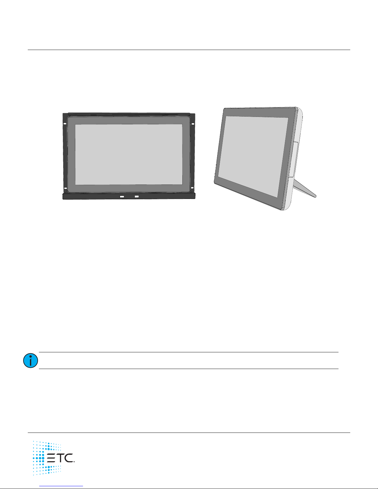
Welcome to the Paradigm 18 inch Touchscreen Setup and Connect Guide. The Paradigm 18 inch
Touchscreen (P-TS18) ships standard with a table top stand and an international power supply. Available
separately, ETC offers a 19” rack mounting kit (P-TS18-RK). Contact ETC for ordering details.
This guide provides table top stand and rack mount installation instructions, as well as information related
to the initial setup and connection of the Paradigm 18 inch Touchscreen (P-TS18) including details to
interface with the Application Shell. Instructions for use of the Paradigm Virtual Touchscreen Software are
available on the ETC website at etcconnect.com.
Features
• 100-240 VAC, 50/60Hz
• High-resolution 1366x768p touchscreen interface
• USB interfaces for theme upload or use of a separate mouse and keyboard (if required)
• Two Ethernet ports for connectivity to the Paradigm network
• Runs Paradigm Virtual Touchscreen Software
• Includes table top stand and installation hardware
- Supports panel, wall, desktop, and swing-arm VESA mounting. Accepts screw type M4 x 8-12mm
(VESA mounting kit and installation hardware provided by others)
Operating Environment
• Supports use of 0-40°C, 5-95% at 40°C non-condensing humidity environment
Note:
P-TS18 is only supported by P-CCS software version 3.0 or later.
P-TS18 installed on
table top stand
(included)
P-TS18 installed into a
19” rack mount kit
(P-TS18-RM) available
separately
Page 2
ETC Setup and Connect Guide
Paradigm 18 inch Touchscreen
P-TS18 Touchscreen Page 2 of 15 ETC
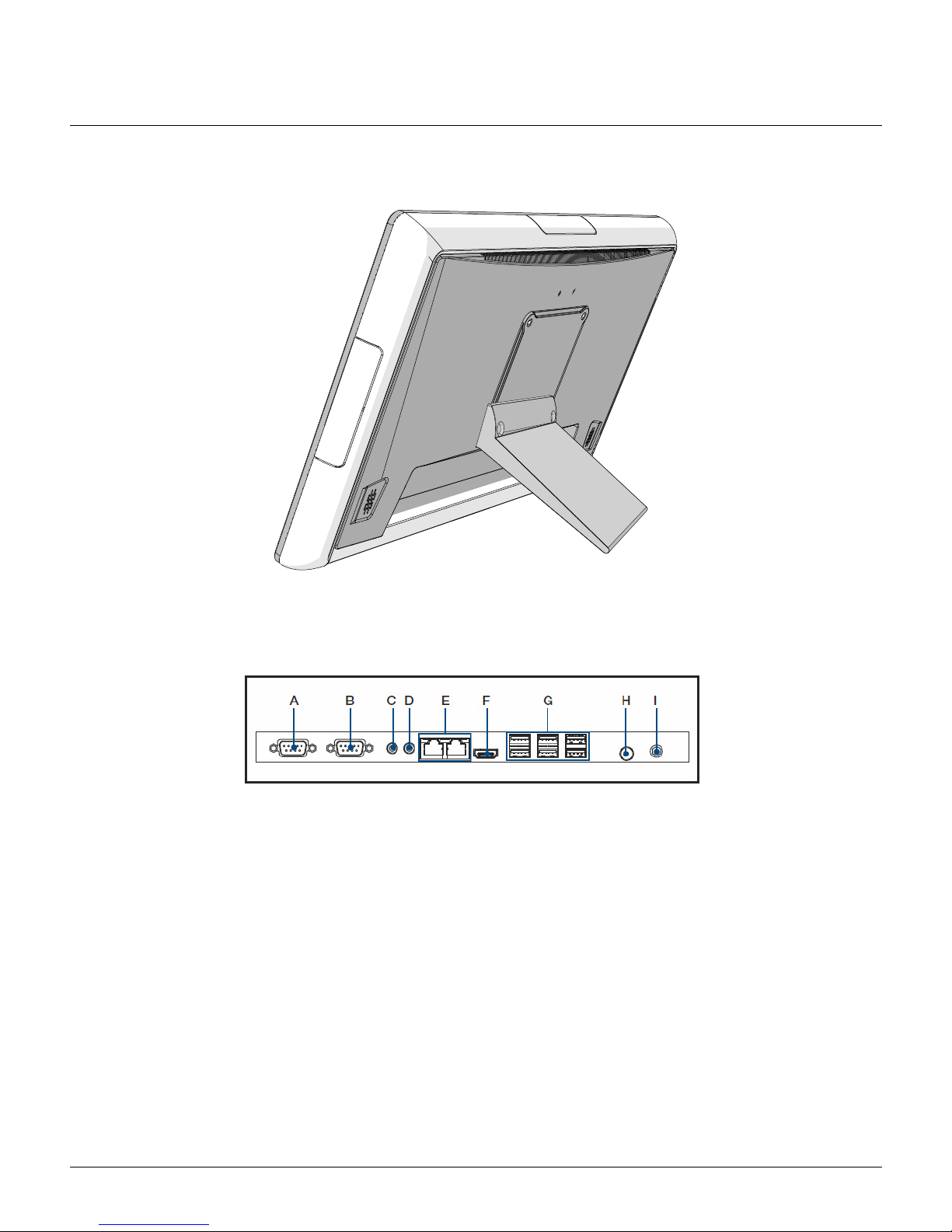
Table Top Stand Mounting
The table top stand accessory is provided with the Paradigm 18 inch Touchscreen.
1: Locate the table top stand and installation hardware in the main packaging with the touchscreen.
2: Align the table top stand to the back of the touchscreen. Reference the graphic above for
clarification.
3: Secure the stand to the touchscreen using two screws (provided).
4: Locate the international power supply and cables from the touchscreen accessory box.
5: Insert the power supply round plug into the Touchscreen “12V DC IN” receptacle, located on the
back of the unit.
6: Using the appropriate power cable adaptor that is required for your region, insert the receptacle end
into the power supply and the plug end into the power source.
7: Connect an Ethernet cable (not provided) between the P-TS18 “Net3 Network” interface, which is
the left-most RJ-45 connector while viewing the back, and the network switch that is also connected
to the Paradigm Central Control Server (P-CCS).
A. COM1
B. COM 2
C. Line-out
D. Mic in
E. LAN ports x 2 (RJ-45)
F. HDMI
G. USB
H. Power button
I. 12V DC IN input
Page 3
ETC Setup and Connect Guide
Paradigm 18 inch Touchscreen
P-TS18 Touchscreen Page 3 of 15 ETC
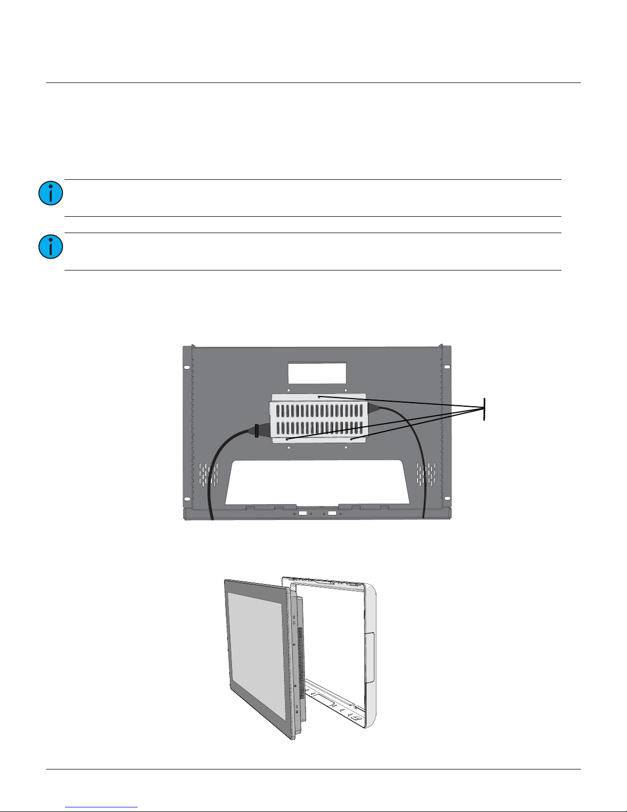
Rack Mounting
The P-TS18 Touchscreen Rack Mount Kit (P-TS18-RK) provides the ability to install the P-TS18 into a 19”
rack, utilizing eight units (8U) of rack space.
Installations
1: Locate the P-TS18, the accessory box from the P-TS18 packaging, and the P-TS18 Touchscreen Rack
Mount Kit.
2: Using the included locknuts, mount the power supply holder with the power supply installed to the
back of the rack mount panel using a 5/16 nut driver.
3: Attach the rack mount panel to the 19” rack enclosure using the four M10 screws, washers, and the
spring clips provided with the Rack Mount Kit.
4: Carefully remove the plastic trim ring from the back of the touchscreen.
Note:
Full access to the front and back of the equipment rack is required during this installation
procedure.
Note:
The P-TS18 ships with a table top stand which is not required when rack mounting.
Recycle or discard the unused stand parts.
Install
Locknuts
Page 4
ETC Setup and Connect Guide
Paradigm 18 inch Touchscreen
P-TS18 Touchscreen Page 4 of 15 ETC
5: To install the P-TS18 into the rack mount panel, insert the top part of the touchscreen into the panel
then gently press the bottom part of the touchscreen into the panel. The touchscreen will be
temporarily held in place by the top and bottom clips on the touchscreen and rack mount panel.
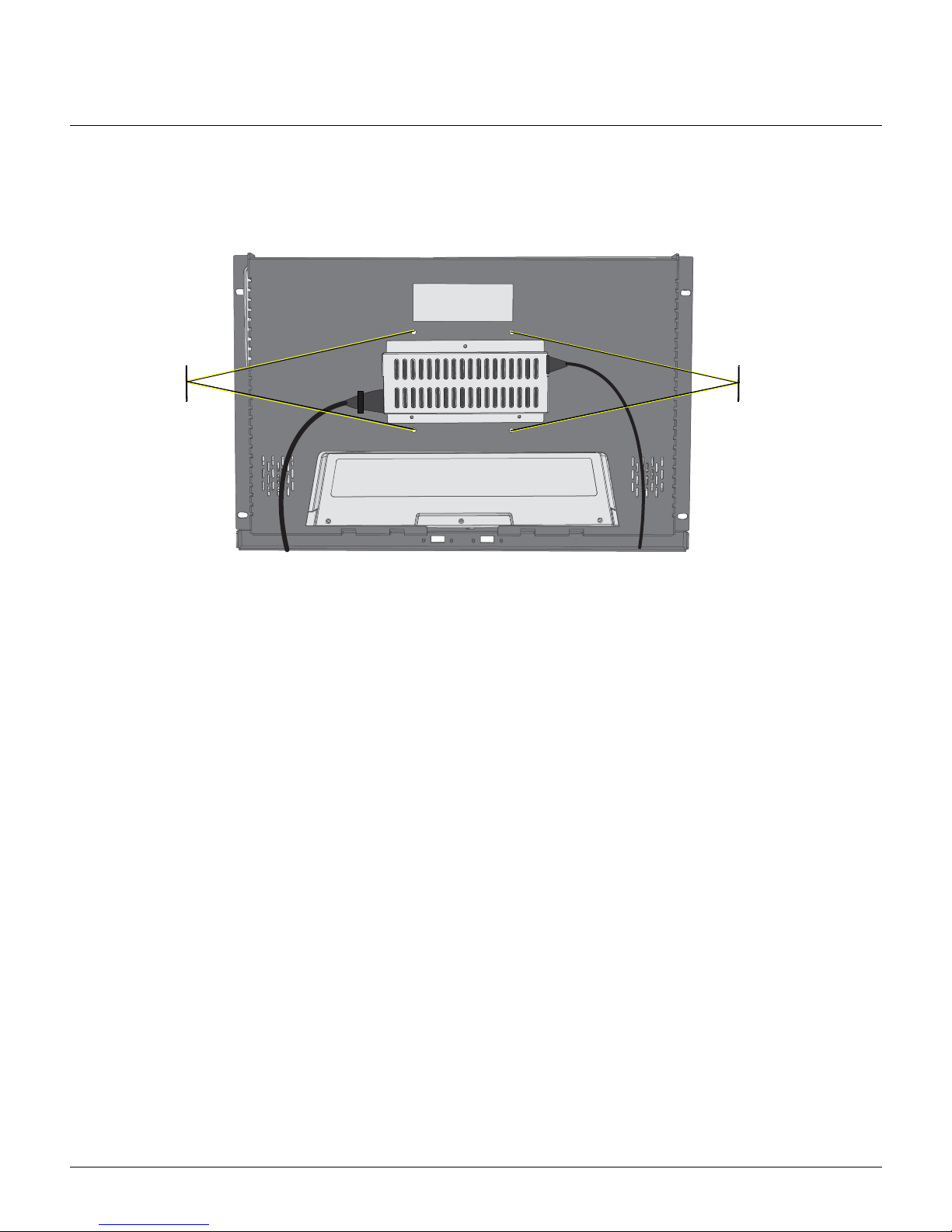
6: Accessing the unit from the rear of the equipment rack, carefully secure the touchscreen to the rack
mount panel using the screws provided.
7: Attach the two USB cables from the rack mount panel to the USB ports on the touchscreen I/O. This
connection allows convenient use of the touchscreen USB ports from the front of the rack mount
panel.
Final Installation
Connect Power and Data
Power
1: Insert the power supply round plug into the “12V DC IN” receptacle located on the back of the
touchscreen.
2: Locate the correct IEC power cable for your region from the P-TS18 accessory box.
3: Attach the IEC cable between the power supply and the power source.
Data
Connect an Ethernet cable (not provided) between the P-TS18 “Net3 Network” interface, which is the leftmost RJ-45 connector while viewing the back, and the network switch that is also connected to the
Paradigm Central Control Server (P-CCS).
Power Up
1: Apply power to the circuit.
2: Reference
P-TS18 Initial Power-up
on
page 5
for further instruction to use the touchscreen and
Virtual Touchscreen Software.
secure
here
secure
here
Page 5
ETC Setup and Connect Guide
Paradigm 18 inch Touchscreen
P-TS18 Touchscreen Page 5 of 15 ETC
P-TS18 Initial Power-up
The P-TS18 boots as soon as it has power. Because ETC has prepared the P-TS18 at the factory prior to
shipment, on initial power-up, Virtual Touchscreen Software loads.
Application Shell
The Application Shell includes the interface to launch the Virtual Touchscreen Software, which was
installed at the factory before shipment. In addition, the Application Shell provides access to the
touchscreen’s IP and network settings, as well as more advanced features which are password protected.
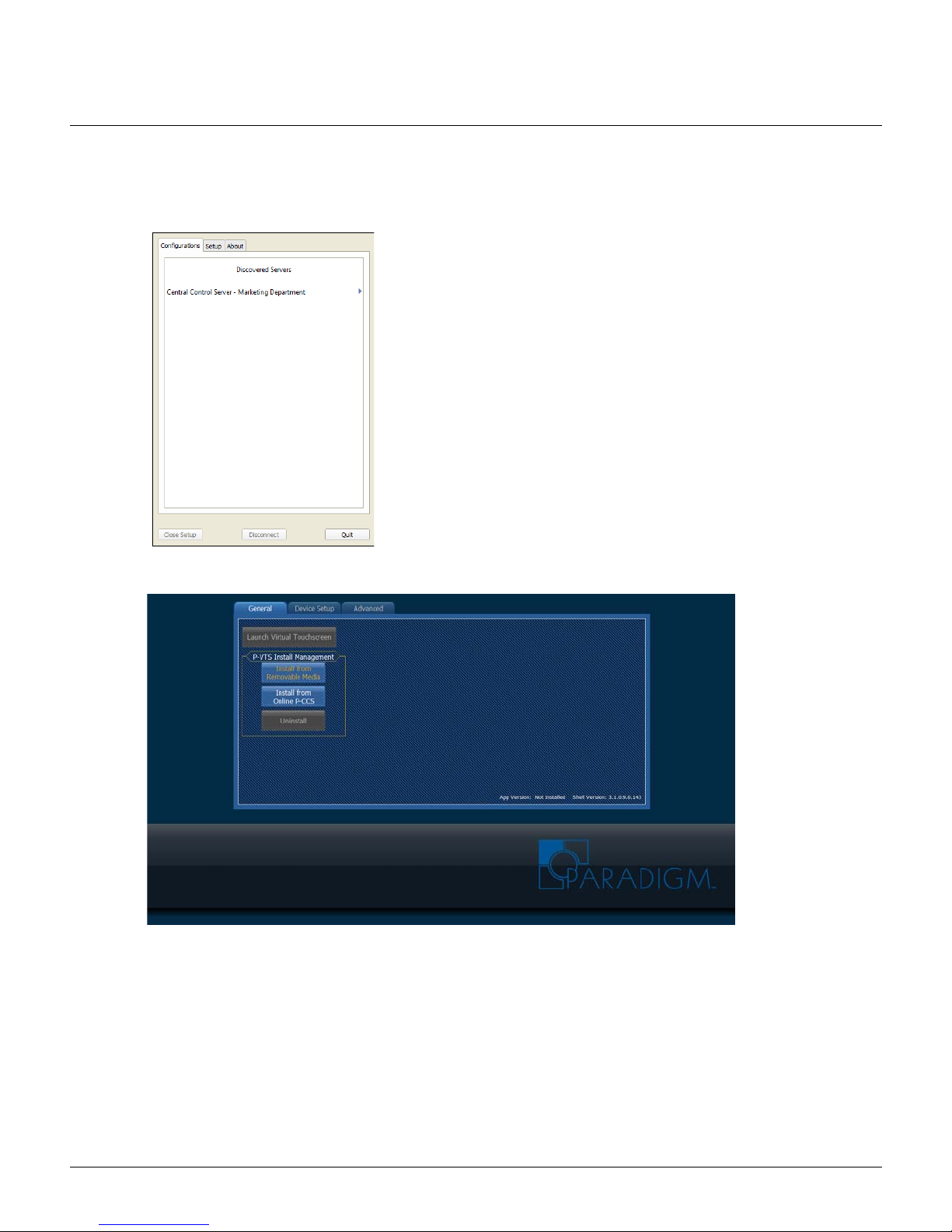
To continue with selecting a Virtual Touchscreen configuration,
touch to select the “Central Control Server” from the “Discovered
Servers” list. Instructions for use of Paradigm Virtual Touchscreen
Software are available on the ETC website at etcconnect.com.
To update Virtual Touchscreen Software, to change IP or network
settings, or for additional advanced features and troubleshooting,
touch the [Quit] button on the bottom right corner of the VTS
application. The VTS application closes and the Application Shell
displays. Reference
Application Shell
for instructions.
Page 6

ETC Setup and Connect Guide
Paradigm 18 inch Touchscreen
P-TS18 Touchscreen Page 6 of 15 ETC
Notice the lower right hand corner of the shell displays software versions of both the “Shell Version” and
the “App Version”. The “App Version” represented is the version of Virtual Touchscreen Software that is
currently installed.
Three tabs are located on the Application Shell including “General”, “Device Setup” and “Advanced”.
General Tab
The “General” tab is provided as the interface to launch and manage the Virtual Touchscreen Software.
[Launch Virtual Touchscreen]
The Virtual Touchscreen Setup Guide is available for download on the ETC website at etcconnect.com.
Install Management
This section of the “General” tab provides the ability to [Uninstall] Virtual Touchscreen Software or install
a newer version from either removable media or the connected Paradigm Central Control Server (P-CCS).
Note:
The Application Shell software is included with each installation of the P-TS18. Updates
to the shell are combined with VTS application updates when necessary.
Note:
Touchscreen configurations are created in ControlDesigner and associated to a Virtual
Touchscreen instance in LightDesigner. Reference the online help systems for
ControlDesigner and LightDesigner for details to create and associate touchscreen
configurations.
Note:
If a current version of VTS is installed, the [Install from Removable Media] and [Install from
Online P-CCS] buttons are disabled. You must first uninstall the software before installing
a new version. Reference [Uninstall] for details.
To launch the Virtual Touchscreen Software touch the
[Launch Virtual Touchscreen] button located on the
“General” tab.
The VTS application launches to the “Discovered Servers”
list. Select the Central Control Server to continue with
configuration selection.
Page 7

ETC Setup and Connect Guide
Paradigm 18 inch Touchscreen
P-TS18 Touchscreen Page 7 of 15 ETC
[Uninstall]
Only one instance of Virtual Touchscreen Software can be installed at a time. You must uninstall any
currently installed software before installing another.
1: Touch to select [Uninstall]. The password dialog displays for password entry.
2: Enter the password into the provided space then touch [Enter]. The Paradigm Virtual Touchscreen
Bundle Uninstall wizard displays for confirmation.
[Install from Removable Media]
Virtual Touchscreen Software installs from removable media (typically USB device). You can retrieve the VTS
application file from the web interface of a connected Paradigm Central Control Server (reference the
documentation for the P-CCS for instructions). You must save the VTS software executable
(“paradigm_vts_installer.exe”) to the root directory of the removable media.
1: Insert the removable media into a USB interface of the Paradigm 18 inch Touchscreen.
2: Touch [Install from Removable Media]. The application wizard will automatically begin installation of
the VTS application. During this installation process, the touchscreen will shut down then restart
again, automatically launching VTS at restart. For instructions on use of Virtual Touchscreen
Software, reference the Paradigm Virtual Touchscreen Setup Guide, available for download on the
ETC website at etcconnect.com.
Note:
The password is set, by factory default, to 4116. Change this password or remove the
requirement for a password in the [Set Password] section of the Advanced Tab.
Note:
P-TS18 is supported by P-CCS version 3.0 software or later.
Note:
The paradigm_vts_installer.exe file must be stored on the root directory of the USB
device.
3: Touch the [Uninstall] button to proceed with the
uninstall process.
4: Touch [Finish] to close the wizard. The Application
Shell returns to the “General” tab where you can
proceed to install another version of the VTS
application from either removable media or an
online Paradigm Central Control Server (P-CCS).
Page 8

ETC Setup and Connect Guide
Paradigm 18 inch Touchscreen
P-TS18 Touchscreen Page 8 of 15 ETC
[Install from Online P-CCS]
Virtual Touchscreen Software installs from any discovered and online Paradigm Central Control Server (PCCS).
1: Touch to select the [Install from Online P-CCS] button.The Application Shell provides a list of all
discovered Central Control Servers (P-CCS) by IP address. Be patient as this process could take up to
a minute depending on network traffic,
2: Touch to select the server IP from the discovered list, then touch the [Install]. During this installation
process, the touchscreen will shut down then restart again, automatically launching the VTS
application at restart. For instructions on use of Virtual Touchscreen Software, reference the
Paradigm Virtual Touchscreen Setup Guide, available for download on the ETC website at
etcconnect.com.
• To cancel the installation and return to the “General” tab, touch [Cancel].
• To request a refreshed list of online and discovered P-CCS, touch [Refresh List].
Page 9

ETC Setup and Connect Guide
Paradigm 18 inch Touchscreen
P-TS18 Touchscreen Page 9 of 15 ETC
Device Setup Tab
Common settings that are required to set up your Paradigm 18 inch Touchscreen including the Network
Connection, IP Address, Subnet mask, Gateway, and Volume and Brightness Settings are available on the
“Device Setup” tab.
Network Adaptor and IP Settings
The “Network Adapter” status on the top of the screen indicates whether a valid Paradigm network is
Online
or
Offline
.
The section for “IP Settings” provides TCP/IP v4 settings for the Paradigm 18 inch Touchscreen.
• Network Connections - always defaults to “Net3 Network”, which is the left-most RJ-45 connector
while viewing the back of the unit, which is where the P-TS18 should be connected.
• Settings for the other network connector can be edited if that interface is used instead,
however the correct interface must be selected from the Setup tab of the VTS application.
• Allows for either Automatic or Manual IP settings. Default setting is Manual (IP address:
10.101.18.101, Subnet mask: 255.255.0.0, Gateway: 10.101.1.1).
- Select Automatic when LinkLocal IP (no DHCP) or DHCP.
- Select Manual to manually set the IP address, Subnet mask, and Gateway IP of the Touchscreen.
With “Manual” selected, touch inside each field to set the numeric values.
Note:
Touch the [Save Changes] button before leaving this tab or the changes will be lost.
Page 10

ETC Setup and Connect Guide
Paradigm 18 inch Touchscreen
P-TS18 Touchscreen Page 10 of 15 ETC
Volume and Brightness and Display Settings
Adjust the volume and brightness settings using the provided sliders. To mute the volume for the
Touchscreen, select the “Mute Sound” checkbox beneath the Volume Settings slider.
Determine the sleep settings for the touchscreen display using the drop down selection box. By default the
display is set to turn off after 15 minutes without user interaction.
Advanced Tab
The “Advanced” tab is password protected by default. The settings and features on this tab are reserved
for technicians and administrators. The password is set, by factory default to 4116. Change the user
configurable password (“4116” always works as a back door) or remove the requirement for a password
using the “
[Set Password]
” feature.
Note:
Touch the [Save Changes] button before leaving this tab or the changes will be lost.
Page 11

ETC Setup and Connect Guide
Paradigm 18 inch Touchscreen
P-TS18 Touchscreen Page 11 of 15 ETC
[File Manager]
Touch the [File Manager] button to display an interface for basic management of files including copy,
move, delete and creation of new folders between the touchscreen internal hard drive and any connected
or removable media.
Copy or Move a File
1: To copy or move a file between connected removable media and the Paradigm 18 inch Touchscreen,
touch to select the file from the list then touch the desired action.
- When copying or moving from the P-TS18 to removable media, select the [Copy>] or [Move>>]
button.
- When copying or moving from removable media to the P-TS18, select the [<Copy] or [<<Move]
button.
2: Touch [Done] to close the File Manager.
New Folder
Create a new folder on either the P-TS18 or the removable media using the related [New Folder] button
beneath each section.
1: Touch the [New Folder] button beneath the desired directory. An alphanumeric keypad displays for
naming of the new folder.
2: Use the keypad to specify the new folder name.
3: Touch the [Enter] button when done. The new folder displays in the directory.
4: Touch [Done] to close the File Manager.
Delete
Delete a folder or file from either the P-TS18 or the removable media using the related [Delete] button
beneath each section.
1: Select the desired folder or file from the directory.
2: Touch the [Delete] button beneath the related directory. Confirmation is required before the file is
deleted.
3: Touch [Yes] to delete the selected file or [No] to cancel.
4: Touch [Done] to close the File Manager.
Page 12

ETC Setup and Connect Guide
Paradigm 18 inch Touchscreen
P-TS18 Touchscreen Page 12 of 15 ETC
[Device Manager]
Selecting the [Device Manager] button displays the Windows Device Manager for access to administrator
hardware and driver support.
[Run...]
Selecting the [Run...] button displays the alphanumeric keypad for specification of a Windows directory
that may be used for advanced troubleshooting.
1: Use the keypad to type the name of a specific folder.
2: Touch the [Enter] button to complete the run command.
Page 13

ETC Setup and Connect Guide
Paradigm 18 inch Touchscreen
P-TS18 Touchscreen Page 13 of 15 ETC
[Collect Logs]
Selecting the [Collect Logs] button displays a dialog that begins the collection process of all logs available
on the PTS-18; including any P-VTS data, or Application Shell data. This information can be useful when
troubleshooting.
1: To display the list of logs that have been collected, touch the [Advanced] button. The collected logs
will display in list form.
2: Touch the [Next] button. A dialog displays for entry of additional information about the problems
experienced, requiring the collection of this log data. Follow the instruction on the dialog then touch
the [Next] button to continue.
3: Select the drive to save the log files from the available drives in the dialog, then touch the [Next]
button to continue.
4: When the log files have saved successfully, touch the [Exit] button to close the dialog and return to
the “Advanced” tab.
Page 14

ETC Setup and Connect Guide
Paradigm 18 inch Touchscreen
P-TS18 Touchscreen Page 14 of 15 ETC
[Set Password]
By factory default, a password is required to access the “Advanced” tab as well as to uninstall the P-VTS
software. The factory set password is “4116”. (This is always available as a backdoor password after
applying a user configured password.)
1: To specify a user configurable password, touch the [Set Password] button. The alphanumeric keypad
displays.
2: Enter the new password and touch the [Enter] button to close the keypad. A dialog will display
confirming the password is set.
Password Enabled
The status of the “Password Enabled” checkbox next to the [Set Password] button determines whether or
not a password is required anywhere in the Application Shell. By default, this checkbox is enabled. To
disable the password requirement, touch the checkbox, leaving the box unchecked.
[Ping Test]
Verify the connection to other networked products, such as the Paradigm Central Control Server
(P-CCS) using the ping utility provided in the Advanced tab.
1: Touch the [Ping Test] button to display the alphanumeric keypad for entry of a specific IP address.
2: Enter the IP address of the host product. 10.101.10.10 is the default IP for a Paradigm Central
Control Server (P-CCS).
Page 15

ETC Setup and Connect Guide
Paradigm 18 inch Touchscreen
P-TS18 Touchscreen Page 15 of 15 ETC
3: Touch [Enter] to send an echo request to the specified IP address. Any responses will be displayed in
a status window.
 Loading...