

Page 1

Power Control Processor
Configuration Manual
For use with the Unison Echo™ Relay Panel, Unison Echo™ Relay Panel Feedthrough,
EchoDIN, and the Sensor® IQ Intelligent Breaker Panel
Version 2.1
Copyright © 2015 Electronic Theatre Controls, Inc.
All rights reserved. Product information and specifications subject to change.
Part Number: 7123M2400-2.1 Rev A
Released: 2015-06
Page 2

ETC®, Unison®, Unison Echo™, and Sensor® are either registered trademarks or trademarks of
Electronic Theatre Controls, Inc. in the United States and other countries.
LonWorks
®
is a registered trademark of the Echelon® Corporation. All other trademarks, both
marked and not marked, are the property of their respective owners.
Page 3

Table of Contents
Introduction. . . . . . . . . . . . . . . . . . . . . . . . . 1
Congratulations... . . . . . . . . . . . . . . . . . . . . . . . . . . . . . . . . . . . . . . .1
Using This Manual. . . . . . . . . . . . . . . . . . . . . . . . . . . . . . . . . . . . . . .2
Symbols . . . . . . . . . . . . . . . . . . . . . . . . . . . . . . . . . . . . . . . . . . . . . . .2
Chapter 1
Overview of Panels . . . . . . . . . . . . . . . . . . .3
Echo Relay Panel Overview . . . . . . . . . . . . . . . . . . . . . . . . . . . . . . .3
EchoDIN Overview . . . . . . . . . . . . . . . . . . . . . . . . . . . . . . . . . . . . . .4
Echo Relay Panel Feedthrough Overview . . . . . . . . . . . . . . . . . . . .5
Sensor IQ Panel Overview. . . . . . . . . . . . . . . . . . . . . . . . . . . . . . . . .6
Option Cards . . . . . . . . . . . . . . . . . . . . . . . . . . . . . . . . . . . . . . . . . . .7
0-10V Dimming Control . . . . . . . . . . . . . . . . . . . . . . . . . . . . . . .7
DALI Control . . . . . . . . . . . . . . . . . . . . . . . . . . . . . . . . . . . . . . . .7
Contact Input . . . . . . . . . . . . . . . . . . . . . . . . . . . . . . . . . . . . . . .8
Ethernet Interface . . . . . . . . . . . . . . . . . . . . . . . . . . . . . . . . . . .8
Ride-Thru Option . . . . . . . . . . . . . . . . . . . . . . . . . . . . . . . . . . . .8
System Concepts and Definitions. . . . . . . . . . . . . . . . . . . . . . . . . . .9
Station Control . . . . . . . . . . . . . . . . . . . . . . . . . . . . . . . . . . . . . .9
Spaces . . . . . . . . . . . . . . . . . . . . . . . . . . . . . . . . . . . . . . . . . . . .10
Output. . . . . . . . . . . . . . . . . . . . . . . . . . . . . . . . . . . . . . . . . . . .10
Circuits. . . . . . . . . . . . . . . . . . . . . . . . . . . . . . . . . . . . . . . . . . . .10
Source Arbitration . . . . . . . . . . . . . . . . . . . . . . . . . . . . . . . . . .10
Zones . . . . . . . . . . . . . . . . . . . . . . . . . . . . . . . . . . . . . . . . . . . . .11
Chapter 2
Table of Contents i
Menu and Configuration . . . . . . . . . . . . . 12
User Interface . . . . . . . . . . . . . . . . . . . . . . . . . . . . . . . . . . . . . . . . .12
Status Indicators . . . . . . . . . . . . . . . . . . . . . . . . . . . . . . . . . . . .12
LCD Display . . . . . . . . . . . . . . . . . . . . . . . . . . . . . . . . . . . . . . . .13
USB Media. . . . . . . . . . . . . . . . . . . . . . . . . . . . . . . . . . . . . . . . .15
Control Button . . . . . . . . . . . . . . . . . . . . . . . . . . . . . . . . . . . . .16
Thru/#Nav Button . . . . . . . . . . . . . . . . . . . . . . . . . . . . . . . . . . .16
Reset Switch . . . . . . . . . . . . . . . . . . . . . . . . . . . . . . . . . . . . . . .16
Navigation . . . . . . . . . . . . . . . . . . . . . . . . . . . . . . . . . . . . . . . . . . . .17
Number Navigation . . . . . . . . . . . . . . . . . . . . . . . . . . . . . . . . .17
Menu Navigation . . . . . . . . . . . . . . . . . . . . . . . . . . . . . . . . . . .17
Menu Structure . . . . . . . . . . . . . . . . . . . . . . . . . . . . . . . . . . . . . . . .18
About Menu . . . . . . . . . . . . . . . . . . . . . . . . . . . . . . . . . . . . . . .18
Switching Setup Menu . . . . . . . . . . . . . . . . . . . . . . . . . . . . . . .20
Page 4

Arch Setup Menu . . . . . . . . . . . . . . . . . . . . . . . . . . . . . . . . . . .26
Timeclock. . . . . . . . . . . . . . . . . . . . . . . . . . . . . . . . . . . . . . . . . . . . .30
Holds . . . . . . . . . . . . . . . . . . . . . . . . . . . . . . . . . . . . . . . . . . . . .30
Timeclock . . . . . . . . . . . . . . . . . . . . . . . . . . . . . . . . . . . . . . . . .31
Schedule Events . . . . . . . . . . . . . . . . . . . . . . . . . . . . . . . . . . . .31
Timeclock Settings . . . . . . . . . . . . . . . . . . . . . . . . . . . . . . . . . .31
Config Holiday Spaces . . . . . . . . . . . . . . . . . . . . . . . . . . . . . . .32
Switching Control Menu . . . . . . . . . . . . . . . . . . . . . . . . . . . . .32
Architectural Control . . . . . . . . . . . . . . . . . . . . . . . . . . . . . . . .33
File Operations . . . . . . . . . . . . . . . . . . . . . . . . . . . . . . . . . . . . .37
View Errors . . . . . . . . . . . . . . . . . . . . . . . . . . . . . . . . . . . . . . . .39
Chapter 3
Appendix A
Appendix B
Appendix C
Service and Maintenance . . . . . . . . . . . . . 40
Service . . . . . . . . . . . . . . . . . . . . . . . . . . . . . . . . . . . . . . . . . . . . . . .40
Contacting ETC about equipment problems . . . . . . . . . . . . .40
Maintenance . . . . . . . . . . . . . . . . . . . . . . . . . . . . . . . . . . . . . . . . . .40
Vacuum the Interior . . . . . . . . . . . . . . . . . . . . . . . . . . . . . . . . .40
Changing Fuses . . . . . . . . . . . . . . . . . . . . . . . . . . . . . . . . . . . . . . . .41
Menu Flow Chart. . . . . . . . . . . . . . . . . . . . 42
Timeclock . . . . . . . . . . . . . . . . . . . . . . . . . . 50
Programming examples . . . . . . . . . . . . . . . . . . . . . . . . . . . . . . . . .50
Astronomical event . . . . . . . . . . . . . . . . . . . . . . . . . . . . . . . . .50
Timed event . . . . . . . . . . . . . . . . . . . . . . . . . . . . . . . . . . . . . . .51
Holiday shut-off . . . . . . . . . . . . . . . . . . . . . . . . . . . . . . . . . . . .52
Status Messages. . . . . . . . . . . . . . . . . . . . . 54
Emergency Active . . . . . . . . . . . . . . . . . . . . . . . . . . . . . . . . . . . . . .54
Breakers Tripped . . . . . . . . . . . . . . . . . . . . . . . . . . . . . . . . . . . . . . .55
Relay Mismatch . . . . . . . . . . . . . . . . . . . . . . . . . . . . . . . . . . . . . . . .55
Relay Removed . . . . . . . . . . . . . . . . . . . . . . . . . . . . . . . . . . . . . . . .55
Breaker Mismatched . . . . . . . . . . . . . . . . . . . . . . . . . . . . . . . . . . . .55
Breaker Removed . . . . . . . . . . . . . . . . . . . . . . . . . . . . . . . . . . . . . .56
Drive 1/2 Error . . . . . . . . . . . . . . . . . . . . . . . . . . . . . . . . . . . . . . . . .56
Breaker Error . . . . . . . . . . . . . . . . . . . . . . . . . . . . . . . . . . . . . . . . . .57
Dim Overtemp. . . . . . . . . . . . . . . . . . . . . . . . . . . . . . . . . . . . . . . . .57
ii Power Control Processor Configuration Manual v2.1
Page 5

Appendix D
Web Interface . . . . . . . . . . . . . . . . . . . . . .58
System . . . . . . . . . . . . . . . . . . . . . . . . . . . . . . . . . . . . . . . . . . . . . . .58
Circuits . . . . . . . . . . . . . . . . . . . . . . . . . . . . . . . . . . . . . . . . . . . . . . .59
Set levels . . . . . . . . . . . . . . . . . . . . . . . . . . . . . . . . . . . . . . . . . . . . .59
Presets . . . . . . . . . . . . . . . . . . . . . . . . . . . . . . . . . . . . . . . . . . . . . . .60
Sequences . . . . . . . . . . . . . . . . . . . . . . . . . . . . . . . . . . . . . . . . . . . .60
Files . . . . . . . . . . . . . . . . . . . . . . . . . . . . . . . . . . . . . . . . . . . . . . . . .61
Table of Contents iii
Page 6

Introduction
Congratulations...
on your purchase of an ETC System with Power Controller Processor. The Power Control Processor
continues ETC’s tradition of providing the highest quality products for the entertainment and
architectural lighting industry. If you have any questions regarding the operation or installation of your
processor, contact ETC Technical Services at the office nearest you.
Emergency service is available from all ETC offices outside of normal business hours.
When calling for help, please have the following information handy:
• Your location and job name.
• Model of breaker or relay Panel(s).
• Type of breakers and relays used including model numbers and quantities.
• Other components in your system including dimmers, switch gear, quantity and type of wall
stations, etc.
• DMX and/or sACN control source used for system-wide control, if any.
• Related system problems or equipment failure.
Americas
ETC International
Technical Services Department
3031 Pleasant View Road
Middleton, WI 53562
800.775.4382 (USA, toll-free)
+1.608.831.4116
service@etcconnect.com
Asia
ETC Asia, Ltd.
Technical Services Department
Room 1801 / 18F
Tower 1 Phase1, Enterprise Square
9 Shueng Yuet Road
Kowloon Bay, Kowloon, Hong Kong
+852 2799 1220
service@etcasia.com
United Kingdom
Electronic Theatre Controls, Ltd.
Technical Services Department
Unit 26-28 Victoria Industrial Estate
Victoria Road,
London W3 6UU, UK
+44 (0) 8896 1000
service@etceurope.com
Germany
Electronic Theatre Controls, GmbH
Technical Services Department
Ohmstrasse 3
83607, Holzkirchen, Germany
+49 (80 24) 47 00-0
techserv-hoki@etcconnect.com
1 Power Control Processor Configuration Manual v2.1
Page 7
Using This Manual
Along with basic maintenance and service procedures for long lasting performance, this manual
contains information on using the Power Control Processor with the following products:
• Echo Relay Panel UL (ERP-UL)
•EchoDIN
• Echo Relay Panel Feedthrough (ERP-FT)
• Sensor IQ Intelligent Breaker System
Each of these products provides professional quality switching of dimmed and non-dimmed loads
controlled by DMX512, Ethernet, or ETC’s Echo’s line of stations. This manual contains the procedures
for operation, service, and maintenance of each of these panels and their associated options.
Symbols
The following symbols are used throughout this manual to alert you to danger or important
information.
Note:
CAUTION:
WARNING:
WARNING:
Please email comments about this manual to: TechComm@etcconnect.com
Notes are helpful hints and information that is supplemental to the main text.
A Caution statement indicates situations where there may be undefined or
unwanted consequences of an action, potential for data loss or an equipment
problem.
A Warning statement indicates situations where damage may occur,
people may be harmed, or there are serious or dangerous
consequences of an action.
RISK OF ELECTRIC SHOCK! This warning statement indicates situations
where there is a risk of electric shock.
Introduction 2
Page 8
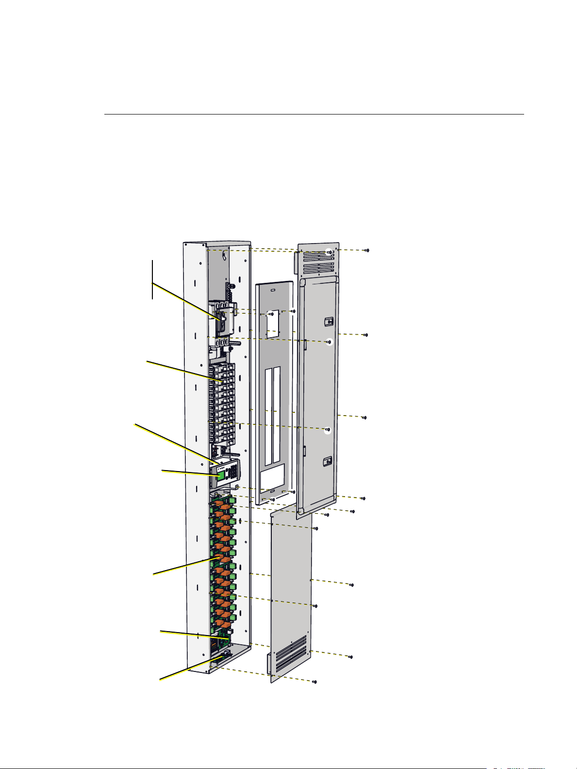
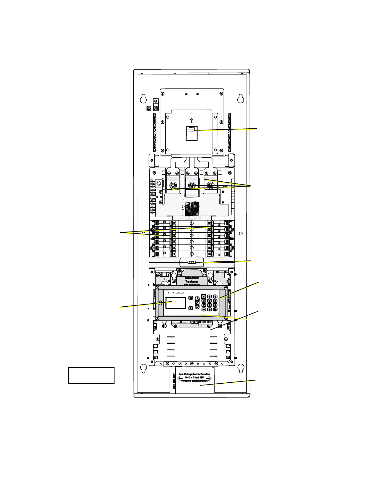
Chapter 1
Cable troughs can be installed
to run the length of the right
or left sides of the panel for
low- voltage cable routing.
Main lugs or
field installed
Main Circuit
Breaker kit
Circuit
Breakers
Relays
Power control
processor
The bottom cover attaches
behind the door, and
overlapping the top cover.
Option cards:
ERP-NET, ERP-CI,
ERP-LVD, ERP-DALI
ERP-RTO installs
behind
processor
I/O Termination
Board
Overview of Panels
The Power Control Processor is designed for use in several of ETC’s power control products.
• Echo Relay Panel UL (Mains Feed), Echo Relay Panel Feedthrough, EchoDIN CE, and
Sensor IQ Intelligent Breaker System
Echo Relay Panel Overview
The Echo Relay Panel UL (ERP-UL) provides professional quality switching and dimming of
loads controlled by DMX512, Ethernet, or ETC’s Echo’s line of stations.
3 Power Control Processor Configuration Manual v2.1
Page 9
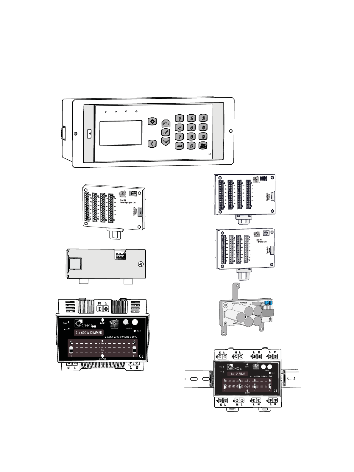
EchoDIN Overview
EchoDIN
DALI Option Card
4-Relay Module
(E-DIN-4 RELAY)
Power Control Processor
The ride-thru option (E-DINRTO) installs on the back
side of the processor
Network
option card
(E-DIN-NET)
Contact input
option card
(E-DIN-CI)
DALI option
card (E-DINDALI)
0-10V option
card
(E-DIN-LVD)
2-Dimmer
Module
(E-DIN-2DIM)
Ride thru
option
(E-DIN-RTO)
The EchoDIN line of products provides professional quality switching and dimming of loads
controlled by DMX512, Ethernet, or ETC’s Echo’s line of stations for the European market. For
system flexibility, all EchoDIN components mount in any DIN rail enclosure provided the
enclosure is grounded and has proper ventilation. For additional information on EchoDIN
products, reference the EchoDIN installation manuals. All ETC manuals are available for free
download at www.etcconnect.com.
Overview of Panels 4
Page 10
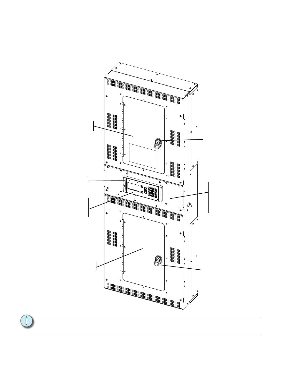
Echo Relay Panel Feedthrough Overview
Power control
processor
The ride-thru option
(ERP-FT-RTO)
installs behind the
UI
Option cards:
ERP-FT-NET, ERP-FTCI, ERP-FT-LVD, ERPFT-DALI are housed
behind the User
Interface panel.
Up to 24 relay
modules
(not shown)
Up to 24 relay
modules
(not shown)
Locking door.
Locking door.
The Echo Relay Panel Feedthrough (ERP-FT) provides professional quality switching and
dimming for up to 48 channels of non-dim loads in a single panel. Loads are controlled by
DMX512, Ethernet, or ETC’s Echo’s line of stations.
Note:
It is possible to retrofit an existing SmartSwitch to an Echo Relay Panel FT. Please call
your ETC project manager or customer service representative for more information.
5 Power Control Processor Configuration Manual v2.1
Page 11
Sensor IQ Panel Overview
The Ride-Thru
option (SQ-RTO)
installs behind the
UI
Remove front panel
for access to option
cards:
IQ-NET, IQ-CI,
IQ-LVD,IQ-DALI
Power Control
Processor
(User interface)
Low voltage
trough
Main lug
Optional Main
Circuit Breaker
installs here
Breakers
Circuit breaker for
user interface
*Door removed
for visual clarity
The Sensor IQ Intelligent Breaker System provides professional quality switching and dimming
of loads controlled by DMX512, Ethernet, or ETC’s Echo line of stations.
Overview of Panels 6
Page 12
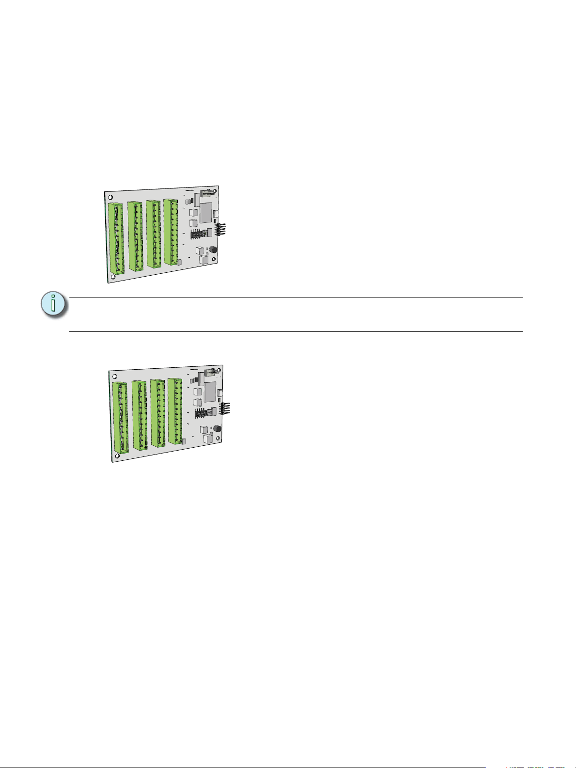
Option Cards
The 0-10V Dimming Control option card provides 24
outputs for control of 4-wire current-sink, 0-10VDC
fluorescent or electronic loads.
• Each of the 24 outputs are rated to control a
maximum of 400mA per channel (up to 50 ballasts
per channel).
• Loss of power at the Echo Relay Panel controller
results in releasing control levels to full.
The Digital Addressable Lighting Interface Control card
controls 24 loops of 64 DALI compatible ballasts in
broadcast mode. Each loop of up to 64 DALI ballasts are
linked one to one with the relay panel circuit for power
control.
The DALI ballast must be powered by an external DALI
loop power supply (supplied by others). This supply is
connected externally of the processor. Each DALI loop
requires its own power supply and possibly more than
one power supply depending on the ballast load.
• Installation is limited to 64 DALI compatible
fluorescent ballasts per DALI loop.
Option cards are available for field installation into each of the panels. Each option adds
another level of features and functions to your system.
For more information on the specification or installation of the option cards, reference the
individual installation manual supplied with the option card.
Option card installation manuals are also available for download at www.etcconnect.com.
0-10V Dimming Control
nt 7-12
nt 13-18
ce
escent 19-24
ores
or
J2 Flu
J1 Flu
escent 1-6
esce
or
or
J4 Flu
J3 Flu
Note:
DALI Control
B A B A
A
B A B A B A
B A B A B A
A
B A B A B A
A
B
A
B
B A
A
B
B A
B A
B A B
B
A
B
B A
A single ERP-UL and ERP-FT supports the use of either the 0-10V Dimming Control
option or a DALI Control option, but not both in the same panel.
A B A
B
7 Power Control Processor Configuration Manual v2.1
Page 13
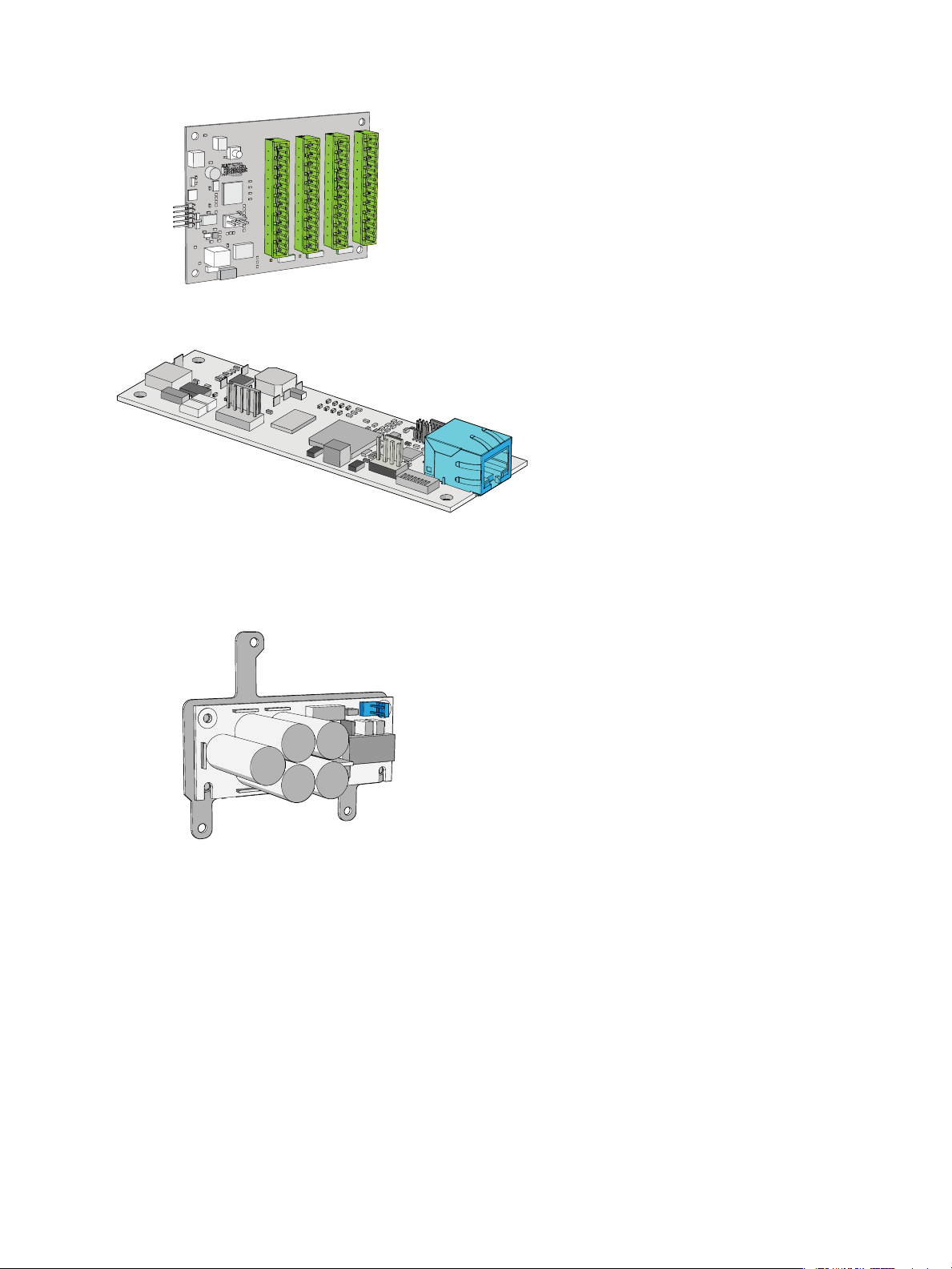
Contact Input
The Contact Input card provides the ability to directly
control the relays using a momentary or maintained dry
contact input.
The Ethernet Interface provides the ability
to control the relay panel using the ANSI
E1.11 (streaming ACN) protocol, allows
feedback of current and voltage
information over the network and through
the web page interface. See “Web
Interface” on page 58.
The Ride Thru Option maintains power to the
Echo Relay Panel controller for a minimum of
15 seconds in the event of a brown-out or
power loss.
• The ERP-RTO option card mounts behind
the user interface.
Ethernet Interface
Ride-Thru Option
Overview of Panels 8
Page 14
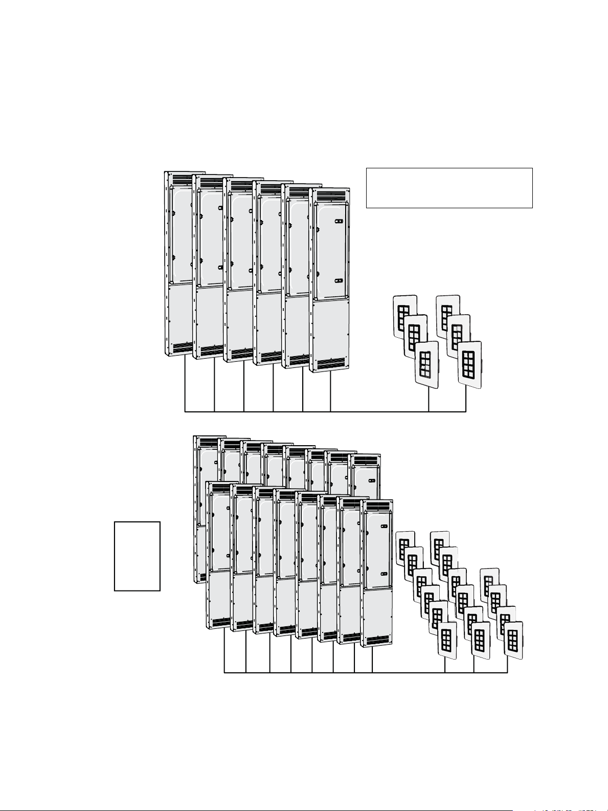
System Concepts and Definitions
EchoConnect - Belden 8471 + (1) 14 AWG ESD Ground Wire
EchoConnect - Belden 8471 + (1) 14 AWG
=
With an
external
power
supply
ERP UL shown. Typical of systems
using EchoDIN, ERP FT, and Sensor IQ
panels.
Station Control
The Power Control Processor supports Echo Inspire Stations, and five and ten button Preset
stations on the EchoConnect bus. The power supply of one connected panel can support up
to six hosts and six stations on the bus. An additional wall mounted or rack mounted power
supply can be added to a system to support up to sixteen hosts and sixteen stations.
9 Power Control Processor Configuration Manual v2.1
Page 15

Note:
CAT5 wiring is supported for the EchoConnect station bus with some limitations. reference
the ETC Cat5 Cable Preparation Setup Guide for more details.
Spaces
Spaces are used to divide the outputs of the relay panel into logical segments (such as
different rooms in a building). Preset, sequence and zone level adjustments all happen within
a “space”. Each panel supports separation of its controllable outputs (relays, 0-10V Dimming
Control and DALI Control) into spaces.
A single panel is limited to eight spaces. An Echo system supports up to sixteen spaces.
Output
An output refers to the physical position of the relay or dimmer in the panel. Up to 48 circuit
outputs are available based on the type of system installed.
• The ERP-FT can be populated with single pole and double pole relays and the ERP-UL can
be populated with single pole, double pole, and three pole relays.
• In an ERP-UL a double pole relay requires two output positions, and a three pole relay
requires three output positions.
• The ERP-UL can be populated with dimmer modules. Each dimmer module is the same
size, and installs in the same manner as a single pole relay module.
Circuits
Circuits are the logical reference number used to talk about a controllable output in the Echo
Relay Panel.
Circuits are unique within a space and are user configurable in software. The combination of
space and circuit provides a unique identification of an output within a system.
For example, a single panel can have two circuit #1’s when they belong to separate spaces.
Source Arbitration
Each panel can accept a variety of control sources including DMX, Streaming ACN (sACN),
presets, sequence, manual set levels, and panic.
Circuit output arbitration is based on the sACN model of source priority, meaning each source
is assigned a priority between 1 and 201 (201 is the highest priority). With this priority, control
sources are arbitrated based on their set priority. The default priority is 100.
The panel uses the priority assigned within the sACN packet, sent from the control source.
Each panel sets the configured priority for DMX, presets, and sequence.
The Contact Input Option card can be used to:
• trigger presets and sequences - which will play at the priority configured for architectural
sources,
• or to directly control one or more outputs. The priority of these outputs is configurable.
If nothing is configured, last action takes precedence.
Manually set levels from the user interface of the Echo Relay Panel overrides all other control
sources with the exception of panic, which is the highest possible priority.
Overview of Panels 10
Page 16

Zones
A Space within an Echo control system can be broken down further into Zones. You can
assign a zone to an Echo Inspire station for direct control using that station’s rotary control or
faders. You can have multiple zones within a space and a single zone can control multiple
outputs across multiple panels.
11 Power Control Processor Configuration Manual v2.1
Page 17
Chapter 2
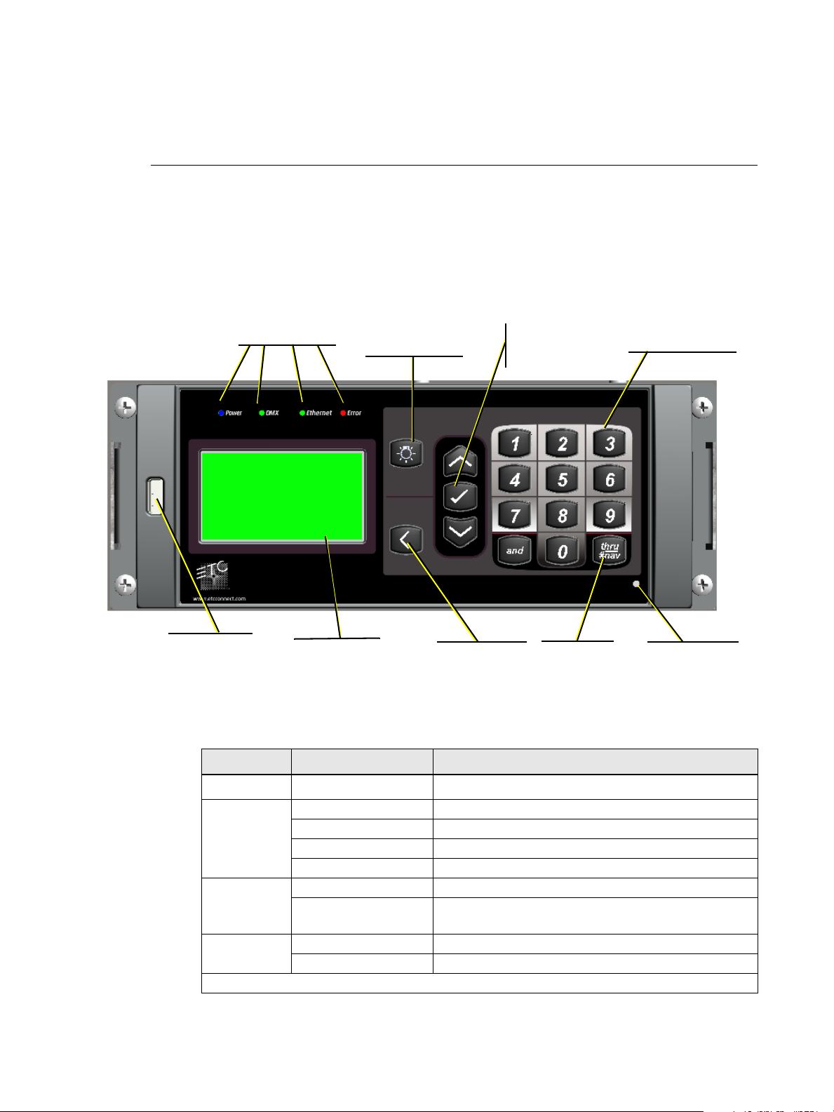
USB port
LCD display
Control button
Back button
status indicators
12 button keypad
Up button
Enter button
Down button
reset switch
Thru/#Nav
button
Menu and Configuration
User Interface
The Power Control Processor features a simple user interface with up and down arrows for
menu navigation, a numeric keypad for direct selection, and an easy to read graphical LCD.
Additionally, a USB port is provided on the left hand side of the controller for storage of
configurations to a flash drive.
Status Indicators
The user interface features the following status indicators:
Menu and Configuration 12
Indicator LED Color Status
DMX
Error
Green Steady DMX input enabled and DMX present
Green Flashing DMX input enabled but no DMX present
Green Rapid Flashing DMX input enabled with DMX input error
Off DMX input disabled
Green Flashing Ethernet activity
Off
Off Not in error state
On Error state
See “Status Messages on page 54” for descriptions of errors.
Power Blue Power on
Ethernet
No Ethernet activity or Ethernet Interface card is not
present
Page 18
LCD Display
Output Status
System OK
DMX Start = 101
DMX Input: Active
v.2 .0.0
L
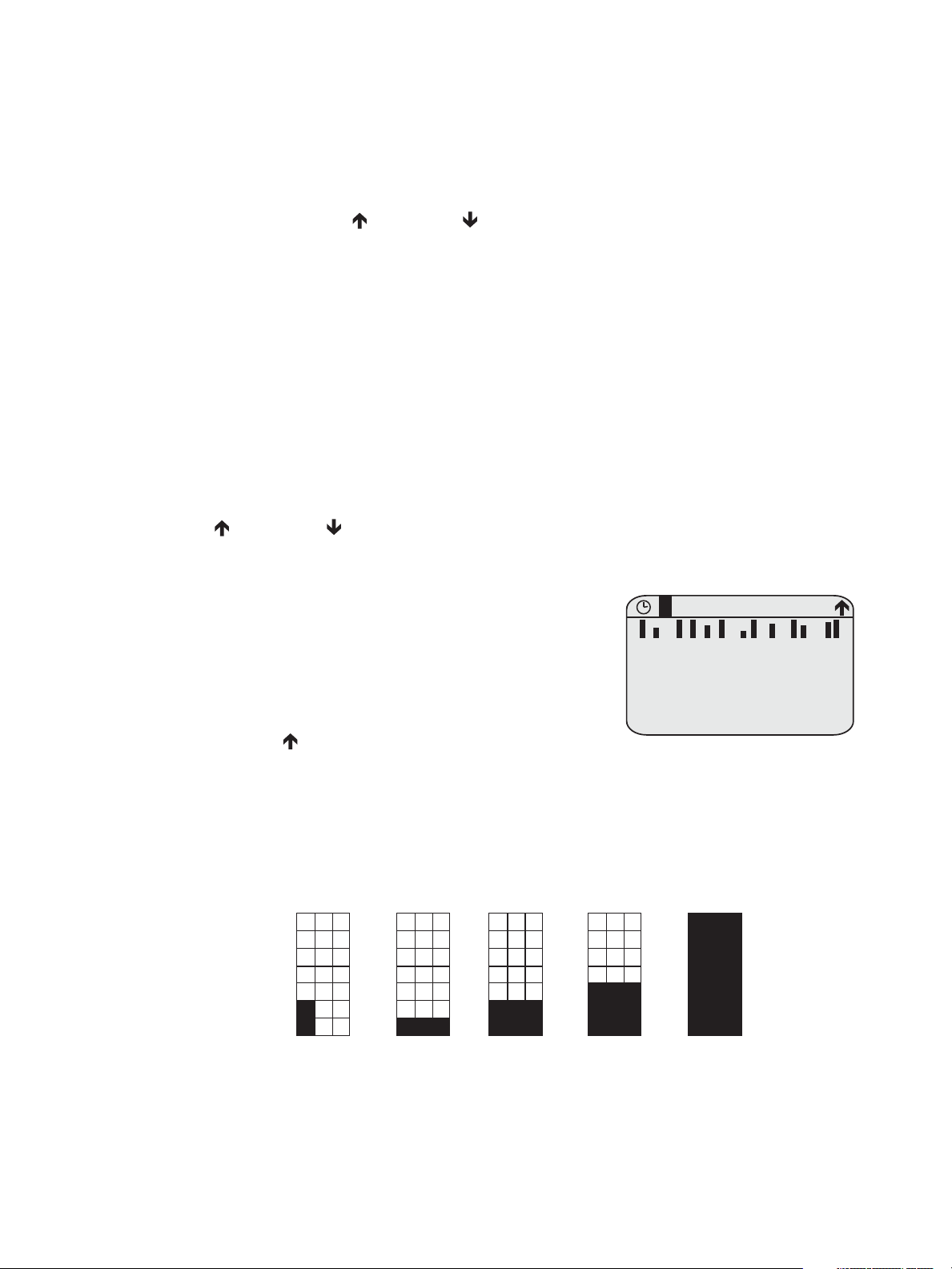
Output Status screen displays several lines of information.
• Line 1 shows the name of the display: Output Status.
• A clock symbol is shown in the upper left corner
when the Power Control Processor has the
timeclock enabled. See Timeclock on page 30 for
more information on timeclock functionality.
• [L] symbol is shown when levels are set.
• The in the upper right corner shows the
option to arrow up to an additional menu.
0% Two
bottom left
pixels used as
place holder
...continue in
steps of 15%
91-100%
16-30%
Bottom two
rows filled
1-15%
Bottom row
filled
The Power Control Processor features a high contrast 21 character, 8 line backlit screen.
When scrolling through the menu, the first row of the LCD display is reserved for the menu
title.
A scroll bar displays along the right side of the screen indicating there is more content to be
displayed. Use the [Up] or [Down] on the user interface to scroll through the available
displays.
Wake
The menu system and LCD backlight are set, by default, to sleep after three minutes of
inactivity. Any button press wakes the user interface and LCD backlight.
Home Screen
The home screen is shown by default at power-up. The home screen is also the default display
that is reverted back to automatically from any point in the menu after two minutes of user
inactivity.
Two displays are available from the home interface, the “Output Status” screen, which shows
information about the current state of the channels, and the “Arch Control Status” screen
which shows current present status information. Switch between the two by pressing the
[Up] or [Down] buttons.
Output Status
13 Power Control Processor Configuration Manaul v2.1
• Line 2 and 3 combine to show blocks representative of the set level.
• Each block shows the status of the channel from left to right with 1 at the left and
the highest number (up to 24) on the right. For racks with more than 24 channels,
a second block is shown for the additional 25-48 channels. Levels are indicated for
each channel in a separate block of pixels. For 0-10V Dimming Control or DALI
Control channels, the level is shown.
Page 19
.
Note:
When relays are installed that occupy more than one output position, only a single
bar is shown per relay.
• Lines 4 and 5 combine to show the rack status. The options in the chart below that
are marked “illuminate error LED” will trigger the red error LED to be lit. The options
that are marked as “cycle with others” share the display by cycling through each
applicable message at a rate of one every two seconds.
Output Status Line Options
Status Message Cause
System OK No other messages active No N/A
Emergency Active Emergency look is active Yes No
Breakers Tripped No voltage detected at one or more relays Yes Yes
Relay Mismatch One or more relays in the rack are mismatched Yes Yes
Relay Removed One or more relays in the rack are not found Yes Yes
Breaker Mismatch
Breaker Removed One or more breakers in the rack are missing Yes Yes
Drive 1/2 Error Unable to communicate to breaker drive board Yes Yes
Timed Event Hold User has applied a timed event hold No Yes
Holiday Shut-off User has activated holiday Shut-off No Yes
Breaker Error Breaker has repeatedly tried and failed to operate Yes Yes
Dim Overtemp Dimmer is in an overtemp state Yes Yes
One or more breakers don’t match the
configuration
Illuminate
Error LED?
Yes Yes
Cycle With
Others?
For more information on status messages see Status Messages on page 54.
Note:
When an Emergency Status is active, no other status indicators will be shown.
Emergency Status will always take precedence over all other status options.
• Line 6 shows the lowest configured DMX Start address value in the Power Control
Processor. If the panel is patched straight (one for one) the equals sign (=) is used. When
the panel is set up with a custom address, approximate equals sign is used instead.
• Line 7 alternates each second between the status of the DMX connection and, when the
ports are enabled, the status of the sACN connection.
• DMX Input will be displayed as either Active, Inactive or Disabled.
• sACN Input will be displayed as either Active, Inactive or Disabled and will only be
displayed when the ACN Option Card is installed.
• Line 8 shows the current Power Control Processor software version number as well
as the status of the station bus power.
Menu and Configuration 14
Page 20

Arch Control Status
Arch Control Status
Presets Active
No Active Sequence
System OK
DMX Start = 101
DMX Input: Active
v.2.0.0
• Line 1 shows the name of the display, Arch Control Status.
Additional symbols may display on the first line:
• Clock symbol is shown in the upper left corner when the
Power Control Processor has the timeclock enabled.
• [L] symbol is shown when levels are set.
• A clock symbol is shown in the upper left corner if
timeclock functionality has been enabled. See Timeclock
on page 30 for more information on timeclock
functionality.
Arch Control Status displays several lines of information:
• Line 2 shows “Presets Active” if any presets are active in the rack. If no presets are active
“No Active Preset” will be shown.
• Line 3 shows “Sequence Active” if the sequencer is active. If no sequence is currently
active, “No Active Sequence” will be shown. Line 3 also shows the rack’s IP address if the
Network Option Card is installed.
• Line 4 and Line 5 combine to show the system status. See “Status Messages” on
page 54.
• Line 6 shows the lowest configured DMX Start address value in the Power Control
Processor. If the panel is patched straight (one for one) the equals sign (=) is used. When
the panel is set up with a custom address, approximate equals sign is used instead.
• Line 7 alternates each second between the status of the DMX connection and, when the
ports are enabled, the status of the sACN connection.
• DMX Input will be displayed as either Active, Inactive or Disabled.
• sACN Input will be displayed as either Active, Inactive or Disabled and will only be
• Line 8 shows the current Power Control Processor software version number as well as
the status of the station bus power.
Backup Power Active
If mains power is not detected, the LCD screen gives a three-second delay followed by the
warning message “BACKUP POWER ACTIVE!”. While this warning is displayed all other menu
screens become inaccessible.
Once mains voltage is restored, the LCD will revert back to the home screen and menu
functionality will return.
USB Media
The Power Controller includes a USB type “A” socket located on the left side of the user
interface. A USB storage device is not included and must be purchased separately.
Use a compatible USB storage device to save and load backup files of your configuration and
to update the Power Control Processor firmware. See “File Operations” on page 37. for
information on file operations.
Compatible USB Storage Device
Use a USB storage device that is pre-formatted with the compatible FAT file system. As
needed you can reformat a USB storage device using a PC with the Windows® operating
system or an Apple® Macintosh® computer. Reference the related operating system’s online
15 Power Control Processor Configuration Manaul v2.1
help for instructions to format the USB media.
Page 21

Control Button
Provides quick access to the control menus. A single press rotates access to the Switching
Control menu and the Arch Control menu.
Thru/#Nav Button
Provides quick access to number navigation mode from the home screen. Each menu item is
preceded by a number, pressing that number on the keypad while in #Nav mode will execute
that menu function. If you are in a menu line where it is possible to enter a numeric value,
pressing this button will act as a thru selection key.
Reset Switch
Reset the Power Control Processor by pressing the reset switch located on the bottom right of
the user interface. Access this reset switch using a blunt push tool, for example the tip of a
ballpoint pen. Outputs from installed Option Cards may change with a reset.
Menu and Configuration 16
Page 22

Navigation
Main Menu
1 About
2 Switching Setup
3 Arch Setup
4 Switching Control
5 Arch Control
6 File Operations
7 View Errors
Quick Rack Setup
Output Count: Auto
DMX Start Addr: 1
sACN Universe: 1
sACN Start Addr: 2
Space: 1
Apply Changes* Only
Apply All
Quick Rack Setup
Output Count: Auto
DMX Start Addr: 1
sACN Universe: 1
sACN Start Addr: 2
Space: 1
Apply Changes* Only
Apply All
To enter the main menu, press the [Enter] ( ) button from the home screen.
Number Navigation
Pressing the [thru/#nav] button on the user interface at
any point accesses the number navigation feature of the
menu. Each number corresponds to a different menu
option, allowing quick navigation through each menu
option.
The main menu includes the following items:
• 1 About - see page 18
• 2 Switching Setup - see page 20
• 3 Arch Setup - see page 26
• 4 Switching Control - see page 32
• 5 Architectural Control - see page 33
• 6 File Operations - see page 37
• 7 View Errors - see page 39
Menu Navigation
List Menu
In a list style menu, use the [Up] or [Down]
buttons to navigate through the menu options. Options
are highlighted with inverse color when they are
selected. Pressing the [Back] (<) button will return to
the previous menu selection. Pressing the [Enter] ()
button will enter the selected menu option.
Settings Menu
1 About
2 Switching Setup
3 Arch Setup
4 Switching Control
5 Arch Control
6 File Operations
7 View Errors
Main Menu
Similar to the list style menu, use the [Up] or
[Down] buttons to move through the options in a
settings menu. Throughout these settings menus, values can be edited by using the [Up]
or [Down] buttons or for numeric entries, as needed use the numeric keypad. Pressing
[Enter] ( ) allows you to begin editing the option, as well as to commit the menu selection
and move to the next item.
17 Power Control Processor Configuration Manaul v2.1
Page 23

Multi Part Options
1 AND 3 THRU 6
Out Address Univ
1: 1 63999
2: 2 1
3: 3 12
4: 126 1
5: NA
6: 1 1
press
Enter
Patch sACN Input
Out Address Univ
1: 201 63999
2: 2 1
3: - 12
4: - 1
5: -
6: - 1
press “201”
then Enter
press
Enter
Patch sACN Input
Out Address Univ
1: 201 1
2: 2 124
3: 202 1
4: 203 1
5: NA
6: 204 1
press “1”
then Enter
About
About Output
Levels Summary
Version Info
Contact Inputs
Space Combine
About Output 1
DMX address: 123
sAC N addre s s: 23 4/412
Type: 1-P ole
Mode: Latch-Lock
Contact: Closed
Current Level: 100%
<push Enter for more>
About Output 1
Contact Level: 100%
DMX Level: 45%
sACN Level: 0%
Arch Level: 33%
Set Level: 0%
Panic/Emer: 100%
<push Enter for more>
About Output 1
Load: 6.5A (767VA)
Breaker: On
Contact: Closed
Voltage: 120VAC
Software: v 2.0.0
<push Enter for more>
press
Enter
press
Enter
Position number shown here
In a multi-part menu, each editable item can be modified by first pressing [Enter] (), then
by using the numeric keypad or the [Up] or [Down] buttons to enter the correct value.
Press the [Back] ( ) button to return to the previous selected field.
Note:
Changes are saved only when [Enter] () is pressed on the last field for the
selection or when “Apply Changes” is selected.
Menu Structure
About Menu
The “About” menu provides information about the Power Control Processor configuration.
About Output
The About Output menu is a three-screen, non-editable menu that gives status information
for each source feeding a relay or breaker.
• To navigate between screens, press [Enter] (). Pressing enter from the third screen
will wrap back to the first screen.
• Select the output position number by either entering a number, or using the [Up] or
[Down] buttons. The selected circuit is highlighted in the top right corner of the
screen.
Menu and Configuration 18
Page 24

• Type: displays the relay or breaker type detected at the selected position. Depending on
Pos Ckt Src Level
1 12 Cont 255
2 1 sACN 125
3 2 Arch 75
4 3 --- -- 5 4 DMX 255
6 5 Emerg 255
7 6 Set 0
panel type, the options are None, 1-Pole, 2-Pole, 3-Pole, and Dimmer.
• Mode: displays the configured mode of the circuit.
Modes Description
Normal
0-10V
Latch/Lock
DALI
Default setting for each circuit. Each circuit functions at a pre-defined
control level.
Used for circuits in conjunction with the 24 Channel, 0-10V Dimming
Control option. The circuit will turn on at 1%, and dimmed levels will be
controlled by the option card
Latch-Lock mode can be used for circuits where extra security is desired
when turning them on or off. To turn the relay or breaker on, the DMX
or sACN level must be held at a certain value for a certain period of time,
and at another value to turn it off. This is similar to a moving light macro.
The values used are configurable, See “Output Setup” on page 20.
Sets the circuit to turn on at 1% when active. Dimming levels are
outputted through the DALI Control option.
• Current Level: displays the current level from the controlling data source for this channel,
in percent (%).
• Contact: displays the state of the relay contact, either closed or open.
The following five menu options display the individual levels (if applicable) for DMX, sACN,
Arch, current set level, Panic/Emergency, and Contact Input.
• Load: displays the load both as amperes and calculated VA. The load value displays and
updates in real-time. Multiple pole relays will show loads for each pole (load (1), load (2),
etc.) For the Echo Relay Panel FT, voltage is not measured so this field will contain a dash.
• Breaker: displays the state of the breaker in the panel as either On or Off.
• Contact: displays state of the relay contact as either Closed or Open.
• Voltage: displays the voltage as received for the output. For Echo Relay Panel UL and
Sensor IQ this is equal to the measured voltage coming into the rack. For EchoDIN, this
is the voltage measured from the relay. For Echo Relay Panel FT voltage is not measured
so this field will contain a dash.
• Software: displays the version number of the installed software.
19 Power Control Processor Configuration Manaul v2.1
Levels Summary
Displays the output information for each position. Use the
[Up] or [Down] buttons to view additional lines of
text. The information provided includes:
• DMX input: DMX
• Streaming ACN: sACN
• Set Levels: Set:
• Preset, Sequence or Zone: Arch
• Emergency Look: Emerg
• Contact Input: Cont
• No Control of Dimmer: ---
• Hold Last Look: DMX or sACN level
Page 25

Version Info
Version Info
Application:
1.2. 3.4.5.0
Network:
2.3.4.5.6.0
DALI 1: 1.2.3.4.5.0
DALI 2: 1.2.3.4.5.0
Co n t a c t: 1.2.3.4.5.0
Space Combine
Space 1: 2
Space 2: 1
Space 4: 4-6
Space 5: 4-6
Space 6: 4-6
Switching Setup
1 Output Setup
2 Patch DMX Input
3 Patch sACN Input
4 Emergency Setup
5 Quick Rack Setup
6 Switching Options
Output Setup 1
Mode: Normal
Type: 1-Pole
Threshold: 1%
Space: 1
Zone: 1
Circuit: 1
Allow Manual: Yes
Min Scale: 1%
Displays the software version for each component installed
in the panel. Possible options include Application,
Network, DALI 1, FLO 1, Contact, Bootloader, Echo
Protocol, Echo MAC.
Contact Inputs
The Contact Inputs menu shows the status of the
information on the contact input card. Each of
the 24 outputs will show a status of “OFF” or
“ON”. Each status is updated in real time and
none are editable. If there is no Contact Input
card installed the screen will read “Contact input
card not installed”
A (+) symbol displays when more information is
not shown because of screen space limitations.
Space Combine
The Space Combine menu shows which spaces are
configured for the rack as well as which other spaces it
may be combined with. If it is not combined with any
other spaces, it will read “None”.
Switching Setup Menu
Contact Inputs
1:OFF 2:OFF 3:OFF
4:OFF 5:OFF 6:OFF
7:OFF 8:OFF 9:OFF
10:OFF 11:OFF 12:OFF
13:OFF 14:OFF 15:OFF
16:OF F 17:OFF 18:O FF
19:OFF 20:OFF 21:OFF
22:OFF 23:OFF 24:OFF
Output Setup
The “Output Setup” menu option allows configuration of
the operation parameters of each position in the panel. As
a new number is accessed, the parameters of the selected
relay or breaker is displayed. Use the [Up] or
[Down] buttons, or the numeric keypad to select either
a single or multiple positions.
If an output is selected that is a multi-pole relay, the
information shown will be duplicated.
When multiple relays or breakers are selected, using the using the [and] and [thru/#nav]
buttons, the top line updates to show as much information as possible for the selection. A (+)
symbol displays when there is more information than the screen has room to show.
Menu and Configuration 20
• Mode: displays the type of load detected in the output position. Options are Normal,
Fluorescent, Latch/Lock, DALI, and Always On. See “About Output” on page 18. for
more information on possible modes.
Page 26

• Type: the following types are available per rack.
Warning
Space and circuit
numbers are already
in use. Auto
assign circuit
numbers?
Yes
No
ERP-UL 1-pole, 2-pole, 3-pole, Dimmer, None
EchoDIN 1-pole, Dimmer, None
ERP-FT 1-pole, None
Sensor IQ 1-pole, 2-pole, 3-pole, None
• Threshold: displays the percentage level at which the relay switches on. The default value
is 50%.
• Space: allows configuration of the space to which the selected outputs are allocated.See
“Spaces” on page 10.
• Zone: allows configuration of the zone to which the selected outputs are allocated. See
“Zones” on page 11.
• Circuit: displays the currently assigned circuit number for the position.
• Allow Manual: dictates what happens when a manual override is made from the
override panel on the front of the unit.
• If set to “yes”: the relay is treated as if the level has been set to full.
• If set to “no”: when a manual override is attempted, the controller will reassert
control and change the relay pack to the state requested by the incoming control
inputs.
• Min Scale: displays the percentage level at which a dimmer switches on. The default is
1%. This field will only show if the output is configured as a dimmer.
Multiselect Space Alteration
When multiple positions are selected and space values are
altered, there is the possibility that the new space will house
multiple circuits of the same number.
For example, space 1 contains Circuits 1-5 and Space 2
contains Circuits 1-10.
In this case a warning will be shown with the option to have
all circuits auto numbered to fit within the selected Space.
•Select [Yes] to complete autonumbering.
•Select [No] to keep circuits as set.
21 Power Control Processor Configuration Manaul v2.1
Page 27

Patch DMX Input
1 AND 3 THRU 6
Output DMX
1: 123
2: 124
3: 12 5
4: 126
5: NA
6: 12 8
press
Enter
Patch DMX Input
Output DMX
1: -
2: 124
3: -
4: -
5: NA
6: -
Patch DMX Input
Output DMX
1: 222
2: 124
3: 223
4: 224
5: NA
6: 225
Press
222,
then
Enter
This editable screen allows for the DMX address of each circuit to be altered.
Step 1: While in the Patch DMX Input menu, select the DMX circuit number on the keypad. If
applicable use the AND or THRU keys to select multiple circuits.
Step 2: Wait 2 seconds for the panel to recognize the requested circuits.
Step 3: Press [Enter] ().
Step 4: Using the keypad, type the required starting DMX address for the selected circuit or
group.
• The panel will consecutively auto fill all additional circuits within the selected
group.
Step 5: Press [Enter] ( ) to commit the selection.
• Pressing “0” then [Enter] ( ) will unpatch a circuit.
• Unpatched circuits are shown as “-”.
• For multi-pole breakers/relays, the DMX address will be shown for the first, or
lowest output of the relay.
For multi-pole breakers and relays the DMX address lives with the first, or lowest pole. All
other poles are shown as N/A. If the breaker or relay is not configured as a multi-pole, all poles
are available.
Menu and Configuration 22
Page 28

Patch sACN Input
1 AND 3 THRU 6
Out Address Univ
1: 1 63999
2: 2 1
3: 3 12
4: 126 1
5: NA
6: 1 1
press
Enter
Patch sACN Input
Out Address Univ
1: 201 63999
2: 2 1
3: - 12
4: - 1
5: -
6: - 1
press “201”
then Enter
press
Enter
Patch sACN Input
Out Address Univ
1: 201 1
2: 2 124
3: 202 1
4: 203 1
5: NA
6: 204 1
press “1”
then Enter
This editable screen allows you to select the patch number for each selected circuit.
Step 1: While in the Patch sACN Input screen, select the circuit position number on the keypad.
To select multiple circuits, se the AND or THRU keys.
Step 2: Wait 2 seconds for the panel to recognize the requested circuits.
Step 3: Press [Enter] ().
Step 4: You will now see the Address column highlighted. Use the keypad to select the starting
patch number.
Step 5: Press [Enter] ( ) to commit the patch number selection.
Step 6: Press [Enter] ( ) a second time to advance to the Univ column.
Step 7: Use the keypad or the up and down arrows to enter the desired sACN universe.
• Only sACN universes that have been configured can be entered. If the number of a
non-configured universe is entered, the panel will reject the value and
automatically revert to the previous setting. For more information on configuring
sACN universes, See “sACN Universes” on page 29.
Emergency Setup
23 Power Control Processor Configuration Manaul v2.1
• Emergency Outputs: allows you to assign each
dimmer to be either on or off when the panic input
is active.
• Emergency Level: the value that the emergency
Emergency Setup
Emergency Outputs:
Emergency Level: 100%
Load Shedding: On
circuits will activate to when the emergency input is
active. Can be set anywhere between 80% - 100%.
The default is 100%.
• Load Shedding: determines what occurs to the
loads in the rack that are not part of the recorded
emergency look. Available options include On or Off, with a default of Off.
• When set to Off, the circuits will remain at their last control level at the time of
emergency contact activation.
• When set to On, the circuits that are included in the emergency look will be turned
on. Any circuits that are not set to be included in the emergency look, will turn off.
Page 29

Quick Rack Setup
Quick Rack Setup
Output Count: Auto
DMX Start Addr: 1
sACN Universe: 1
sACN Start Addr: 2
Space: 1
Apply Changes* Only
Apply All
The “Quick Rack Setup” menu option can be accessed
from the main menu.
CAUTION:
The “Quick Rack Setup” operation will erase your rack’s configuration and
generate a new one. It is recommended to make a backup of your
configuration before entering this menu option.
• Output Count: When Auto is selected, the numbering and arrangement of the outputs
is automatically detected by the presence or absence of breakers and relays. When a
number is entered in place of Auto, the rack assumes that number of relays. Any output
positions where relays or breakers are not detected are assumed to contain a single pole
option.
• DMX Start Address: Displays the first DMX address used for patching. The default is to
#1.
• sACN Universe: Displays the first sACN universe in the panel (1-63999).
• sACN Start Address: Displays the first sACN address in the panel (1-512).
• Space: Determines the space to which all relays or breakers in the rack will be assigned.
• Apply Changes* Only: Only the items that have been changed shall be applied.
• Apply All: All items will be applied regardless if they have been changed or not.
• For example, if a DMX start address of 510 is entered and Apply All is selected, the
panel’s auto-fill feature may causes consecutive addresses to extend beyond the
allowed 512. In this instance the panel will automatically unpatch all circuits with
an invalid address by assigning them to DMX zero.
• The same is true if an sACN address entry causes an address overflow. All relays or
breakers holding invalid addresses will be unpatched by assigning them to zero.
The Quick Rack Setup operation automatically assigns addresses to the outputs in the rack.
• In EchoDIN, numbering is sequential from left to right across the relay modules.
Menu and Configuration 24
Address Assignment
Page 30

• In Sensor IQ, ERP-FT, and ERP UL, the numbering is based on a left to right (horizontal)
Position 1Position 1
1-Pole1-Pole
Position 3Position 3
1-Pole1-Pole
Position 5Position 5
1-Pole1-Pole
Position 2Position 2
3-Pole3-Pole
Position 6Position 6
3-Pole3-Pole
Position 4Position 4
3-Pole3-Pole
Position 7Position 7
1-Pole1-Pole
Address 1Address 1
4 channels4 channels
Address 2Address 2
4 channels4 channels
Address 3Address 3
4 channels4 channels
Position 9Position 9
2-Pole2-Pole
Position 11Position 11
2-Pole2-Pole
Position 8Position 8
1-Pole1-Pole
Position 12Position 12
1-Pole1-Pole
Position 10Position 10
1-Pole1-Pole
Numbering moves across
then down.
Set to:
Channel 1
DMX 1
Space 1
sACN ch 1
Set to:
Channel 3
DMX 3
Space 1
sACN ch 3
Set to:
Channel 5
DMX 5
Space 1
sACN ch 5
Set to:
Channel 7
DMX 7
Space 1
sACN ch 7
Set to:
Channel 9
DMX 9
Space 1
sACN ch 9
Set to:
Channel 2
DMX 2
Space 1
sACN ch 2
Set to:
Channel 8
DMX 8
Space 1
sACN ch 8
Set to:
Channel 10
DMX 10
Space 1
sACN ch 10
Set to:
Channel 12
DMX 12
Space 1
sACN ch 12
EchoDIN
ERP-UL,
ERP-FT &
Sensor IQ
Switching Options
Relay Delay: 0ms
LatchLock On: 40-50%
L/L On Time: 5s
LatchLock Off: 0-90%
L/L Off Time: 5s
and then down (vertical) sequence as shown below.
Switching Setup
25 Power Control Processor Configuration Manaul v2.1
This menu allows for configuration of switching delay and
LatchLock settings.
• Switching Delay: delay when outputs turn on, in
milliseconds. Outputs turn on in sequential order.
• LatchLock On: displays the input control level range
that causes the “On Time” to start; shown in 10%
ranges.
• L/L On Time: Must be set before a circuit is switched
on with LatchLock. Default of five sec.
• LatchLock Off: displays the input control level range that causes the “Off Time” to start.
• L/L Off Time: must be set before a circuit is switched off in LatchLock. Default of five
seconds.
Page 31

LatchLock Mode
Level
Time
LatchLock On Range
LatchLock On Time
LatchLock Off Range
LatchLock Off Time
In this range the control source can go
to any level, as long as it does not stay
in the off time range for more than the
latchlock off time value
Control Level
Relay Closes
Relay Opens
Arch Setup
Station Power: On
Remote Record: On
Data Source Settings
Data Loss &Power On
Preferences
Spaces Setup
Network Settings
Contact Inputs
Tim e clock
Latch Lock mode provides added security against incidental turn-on or turn-off of critical
circuits. It requires that the control level remains in a specific range for a specific amount of
time in order to switch on or off the circuit.
To illustrate this example:
Arch Setup Menu
Menu and Configuration 26
Station Power:
determines whether or not the built-in Echo station power
supply is turned on or off. Default is Off. Only one Echo
station power supply should be turned on in an entire
system. See Station Control on page 9 for more information
about station topologies.
Remote Record:
controls whether preset record is allowed from connected
Echo Preset Stations. Options include On or Off. Default is
Off.
Data Source Settings
• DMX Input: determines if the DMX input port to the controller is Enabled or Disabled,
the default is Enabled.
• DMX Priority: determines priority level at which the DMX input will be treated in the
prioritization. Reference Source Arbitration on page 10 for more information about
source prioritization. The default value is 100.
Page 32

• Arch Priority: determines the playback priority to be used for preset, sequence and zone
DMX Loss Behavior
Mode: Wait and Fade
Wait Time: 0min 0sec
Fade Time: 0min 3sec
sACN Loss Behavior
Mode: Hold Last Look
Wait Time: Forever
Power On Behavior
Power On: Last-Look
• Mode: may be set to “Wait and Fade”, or “Hold Last
Look”. Loss behavior defaults to “Hold Last Look”.
• Hold Last Look holds any active dimmers at whatever
levels they were receiving prior to the loss of data. The
last levels are retained until data is restored or another
source takes control.
• Wait and Fade holds the last levels received when the
data was lost for a user-defined amount of time and
then fades those input levels to zero intensity using a
user-defined fade time. The default wait time setting is
three minutes and zero seconds. The default fade time
setting is zero minutes and three seconds.
activations controlled by the connected Preset Stations. Last action takes precedence.
Reference Source Arbitration on page 10 for more information about source
prioritization. The default value is 100.
• Contact Priority: determines the priority of the contact input source. The range can be
set from 1-201 with a default of 100.
• Packet Delay: allows the controller to manage the number of times a DMX value must
be present before acknowledging and reacting to that value.
With the default setting of “0”, the panel will react the first time it receives a valid DMX
command. With the max setting of “10”, the panel will react after receiving the same
DMX command ten times.
Note:
DMX refreshes approximately 40 times per second.
Data Loss & Power On
• Data Loss Settings: this selection displays a sub-menu that allows configuration of the
DMX Loss Behavior, sACN Loss Behavior, and Power on Behaviors.
Note:
.
If the Ethernet Interface option card is not detected, the sACN loss behavior will not
be shown.
• Wait Time: determine the wait time in minutes and seconds if the mode is set to “Wait
• Fade Time: determine the fade time in minutes and seconds. Range is from 0-59 minutes
• Power On Behavior: determine the behavior for the control when the Power Control
• Last-Look: relays remain in their positions from the last power cycle, when the controller
• Off - relays go to Off when the controller is powered up, if there is no active control
27 Power Control Processor Configuration Manaul v2.1
and Fade”. Range is from 0-59 minutes and 0-59 seconds. The default wait time is 3
minutes, 0 seconds. If the mode is set to “Hold Last Look”, the time displays as “Forever”
and cannot be modified.
and 0-59 seconds. The default is 3 seconds.
Processor powers on. Options include “Last-Look” and “Off”. The default is “LastLook”.
was powered up, if there is no control source.
source for DMX or sACN.
Page 33

Preferences
Preferences
Backlight Mode: Auto
Backlight Time: 3:00
Contrast: 100
Language: English
Setup Spaces
Space Name
12 BlackB
4 Main
IP Address
Type: M a n u a l
I P: 1 0 .1 0 1.16 5 .1 0 1
Mask: 2 5 5.2 5 5.0.0
G w a y: 1 0 .1 0 1.16 5 .1 0 1
Apply and Exit
MAC: 0 0:c O:16:a a:b b:c
• Backlight Mode: the backlight has three possible modes
of operation including Auto, On, or Off. The default is
Auto.
• Auto: Keeps the LCD screen backlight illuminated
after boot up and after last button push for a
specified amount of time.
• On: Keeps the LCD backlight illuminated at all times.
• Off: Turns off the backlight illumination.
• Backlight Time: controls the length of time before the backlight turns off when in Auto
mode. The default is 3 minutes; it can be set from 0:10 sec to 9:59 min.
• Contrast: contrast settings can be set from 1-100 from this screen or the home screen
• Language: default setting is English.
Spaces Setup
For an explanation of spaces and their uses, reference Spaces
on page 10.
• Space: the space number can be set from 1-16. A
setting of zero, represented by a dash (-), indicates a
space which is unused. Rows 2 through 8 may be set to
zero, but one space must always be configured.
• Name: the configured name of this space is displayed for reference, but cannot be edited
from the user interface. Space names are configurable through ETC’s software for the
Power Control Processor. The name is limited 12 characters and may be truncated in this
display if it is configured longer.
Note:
If a space is changed to another number after circuits are assigned to it, another
warning dialog will ask for confirmation. If “Yes” is selected, any circuits using that
space will be re-assigned to the new space and may be re-numbered.
If a space is disabled with circuits assigned, a warning dialog will ask for confirmation.
If “Yes” is selected, any circuits using that space will be un-patched (having their
circuit numbers set to zero), control will be released and the output will be set to Off.
Network Settings
Network Setup provides editing and setup related to the Ethernet Interface option card
including IP address configuration and sACN universe setup. These settings, along with the
web interface, are only available when the Ethernet option card is installed. For more
information on the web interface See “Web Interface” on page 58.
IP Address
Allows editing and setup of the network properties of the
Ethernet Interface option card. Two options are available
including Automatic and Manual. Default is Automatic.
• Automatic: the Ethernet Interface option will attempt to
acquire an address from an Address (DHCP) server on
the network. If a DHCP server is not found, the card will
default to a Link Local address for the current power cycle.
Menu and Configuration 28
Page 34

• Manual: manual entry of an IP address, Subnet Mask, and Gateway are allowed. The
sACN Universes
Universe A: 63999
Universe B: 12
Universe C: 233
Universe D: -
Contact Input
Contact: 1
Action: Output Control
Output: 1 thru 1
Contact Type: Toggle
Contact Input
Contact 1
Action: Preset
Space: 1
Preset: 1
Mode: Activate
Contact Input
Contact 1
Action: Sequence
Space: 1
Mode: Activate
Preset Action
Sequence Action
default IP and Gateway addresses will be 10.101.1.1. The default Subnet Mask will be
255.255.0.0.
sACN Universes
Allows configuration of the sACN universes that are available
for patching. The Ethernet Interface option card supports up
to four sACN universes.
Each universe must be set to a valid sACN universe number
between 1 and 63999 or zero (entered as 0, but shown as -),
to indicate that universe is unused.
When a value is changed, any output currently set to that universe will be reconfigured to the
new universe.
Contact Inputs
There are 24 contact inputs available in the panel. These
inputs can be configured for one of several actions. This
menu updates in real time as the action of the contact
input changes.
• Contact: Displays the number of contacts configured
within the panel.
• Action: Options are Output Control, Preset and
Sequence.
• Output Control: Allows the contact to control one, or a range of outputs. If a
dimmer is included in the range it will be toggled to full in the same manner as a
relay.
• Preset: allows you to configure a preset to be activated, deactivated, or toggled on
a contact closure.
• Sequence: allows you to configure a space in order to activate, deactivate or toggle
a sequence.
29 Power Control Processor Configuration Manaul v2.1
• Output: Displays the range of contacts controlled from a single contact input: 1 thru
48.
• Contact Type: Options are Normally Open, Normally Closed, or Toggle.
Page 35

Timeclock
The Timeclock allows built in timed event control for your system.
The Timeclock includes the following features:
• 24-hour timeclock with user configurable daylight savings time (DST).
• Recurrence settings including everyday, weekday, weekends and day of week.
• 50 field programmable events including preset activate, sequence, and off.
• Manual control of presets with override capability.
• Current event manual “hold” up to two hours with the option to manually cancel before
those two hours expire.
• Automatic schedule resumption after a power loss.
• Holiday Shut-off configuration by space.
Holds
A Hold can be triggered to override a scheduled event, preset, or sequence during normal
operation. When a Hold is active, regularly scheduled events are ignored. The timeclock
interacts with the presets and sequences to determine specific hold-behavior. The response
differs depending on the scheduled event and the type of hold that is currently active.
When an active Hold is cleared, the originally scheduled event is restored. Any manual control
without an active Hold condition only temporarily changes the current state of the Echo
system. The next event will execute according to its schedule.
Timed Hold
A Timed Hold occurs when a scheduled event is interrupted by manually triggering a preset or
sequence. Set Auto Timed Hold within the Schedule Events Menu to dictate if an event
responds to a manually activated preset or sequence.
A Timed Hold will automatically clear after two hours (120 min).
Indefinite Hold
Indefinite Hold is enabled through the Arch Control menu. Select “Start Indefinite Hold” to
start an Indefinite Hold.
While an Indefinite Hold is running, all other scheduled events will be overridden and will not
occur. When the Indefinite Hold is cleared, the current schedule is reinstated.
Holiday Shut-Off
The Holiday Shut-Off feature is provided for CA Title 24 compliance to provide an easy way to
temporarily disable the schedule and turn lighting off in designated spaces for 1-7 days with
the default being 1 day.
When “Start Holiday Shut-Off” is selected, the program begins a five minute countdown. At
any time during this countdown, you may cancel the Holiday Shut-Off by pressing the [Back]
button.
After five minutes, Shut-Off plays in the specified spaces.
If manual control is initiated during Holiday Shut-Off, a Timed Hold will start to temporarily
permit the manual lighting control. When the hold time expires, lights shut off in specified
spaces replacing any manual control and Holiday Shut-Off is reinstated using the time
remaining.
Menu and Configuration 30
Page 36

Timeclock
Time clo ck
Timeclock: Enabled
Schedule Events
Tim e clock Settin gs
Config Holiday Spaces
Timed Hold Active
AUG 05, 2015 Hr:Min AM/PM
Schedule Events
Event Nu mber 1
Action: Preset
Space: 1
Preset: 1
Recurrence: Everyday
When: Time of Day
Tim e: --:-- am
Auto Timed Hold: Yes
Displays as either Enabled or Disabled.
Schedule Events
Allows for programming of both timed events that happen
at a specific time, and astronomical events that happen
relative to sunrise or sunset.
• Event Number: Defaults to last known selection.
• Action: Options are Preset, Sequence, and Off.
• Space: Options are dependant on the previous Action settings and show 1-16. The
default is 1.
• Preset: Also dependant on the previous Action setting,
options are 1-64 with a default of “1”.
• Recurrence: Options are Everyday, Weekdays,
Weekends, and each day; Monday-Sunday. Default is
“Everyday”.
• When: Opens a new menu screen where you can select
one of the following; Time of day, Before Sunrise, After
Sunrise, Before Sunset, or After Sunset.
• Time: Allows you to enter hh:mm am/pm with a default
of 12:00 am. Options are dependant on the settings in
the When menu.
• Auto Timed Hold: Indicates if a timed hold has been programmed.
Timeclock Settings
• Time: AM and PM will only be shown when in 24 hour
• Time Style: Options are 12 hour or 24 hour
• Date: Enter as MM/DD/YYY
• Hold Time: Enter in minutes from 30-360. The default is
• Flick Warn: Options are Yes or No. Yes is the default.
• Warn Time: Options are 1-10 min with 2 minutes as the
• Time Zone: GMT -12 through +13 are the options with
• Latitude: Use the keypad to enter, system defaults to N
• Longitude: Use the keypad to enter, system defaults to W (west)
• DST: Options include None, Manual, EU or US, with US as the default.
• Manual DST Dates: Additional menu options allow you to manually enter the month,
31 Power Control Processor Configuration Manaul v2.1
Note:
mode.
120 minutes.
default.
a default of -6.
Tim e clock Settin gs
Tim e: 3:45PM
Time Style: 24 Hour
Date: Jun/07/2014
Hold Time: 120 min
Flick Warn: Yes
Warn Time: 2 min
Time Zone: GMT-6
Latitude: 43 8 N
Longitude: 89 20 W
DST: US
Manual DST Dates
(north)
day, and occurrence of daylight savings/standard time. For more details, See “Menu
Flow Chart” on page 42.
For Times, Date, Latitude, and Longitude fields, using the [Back] (<) button will
automatically discard all edits.
Page 37

Config Holiday Spaces
Switching Control
1 Set Levels
2 Output Check
3 Release Set Levels
All spaces default to “Shut-Off” but can be
individually configured to be unaffected. Spaces that
are configured to “Shut-Off” will not execute any
presets, sequences, or timed events normally
scheduled for the space.
Spaces set to “Unaffected” will continue to allow
normally scheduled events and remain unaffected by
a Shut-Off in other spaces.
To change the configuration for a space:
Step 1: Navigate to the “Config Holiday Spaces” menu.
Step 2: Press [Enter]. The spaces configured to the system will display along with their Shut-Off
status.
Step 3: Scroll through the menu using [Up] and [Down] to select the space to be changed.
Step 4: Press [Enter] to Select the space.
Step 5: Use [Up] and [Down] to choose the option required for the space, either “Unaffected”
or “Shut-Off.”
Step 6: Press [Enter] to commit the selection.
Step 7: Repeat steps for all required spaces.
.
Config Holiday Spaces
Space 1: Shut-Off
Space 2: Shut-Off
Space 3: Shut-Off
Space 4: Shut-Off
Space 5: Unaffected
Space 6: Shut-Off
Space 7: Shut-Off
Space 8: Shut-Off
Note:
For examples of timed event programming See “Timeclock” on page 50..
Switching Control Menu
The Switching Control menu is provided to set output
levels, check outputs, and release any set output levels.
Direct access to the “Switching Control” menu is also
available by pressing the [Test] ( ) button on the user
interface.
Set Levels
The Set Levels menu option allows you to select circuits by slot number and manually set them
to a level. All configured relays/breakers are listed.
• NA indicates a position that is either part of a 2 or 3 pole relay, or where no relay exists.
• “-” indicates the dimmer is released from or is not under Set Level control.
To set output levels:
Step 1: Use the numeric keypad including the [and] and [thru] buttons to specify a circuit, or
range of circuits.
Step 2: Press [Enter] ( ) to accept the selection.
Step 3: You will now be in the value field. Type in a level value.
Menu and Configuration 32
Step 4: Press [Enter] ( ) to apply that level or [Back] (<) to discard it.
When you exit the “Set Levels” menu option, you will be prompted for confirmation of
whether you would like to “Release Set Levels”.
• Selecting “Yes” returns all set levels to the default value.
Page 38

• Selecting “No” causes all set levels to remain until released.
Output Check
Position: 1
Check Level: 100%
Next Output
Previous Output
Arch Control
1 Presets
2 Sequences
3 Start Timed Hold
4 Start Holiday Shutoff
5 Start Indefinite Hold
Presets
Space: 1
Preset 12 Active
Preset#: 2
Activate/Deactivate
Record
Fade Time: 0min 2sec
The “Presets” menu provides you with the tools to select,
activate, deactivate, record, and configure presets.
Output Check
The Output Check menu option allows for checking
outputs individually.
• Position: Defaults to position “1”. It is then
possible to scroll through all outputs to perform
a quick functionality check. Output position
numbers will roll over from one to the maximum,
and vice versa.
• Check Level: use this field to set the percentage
that each position will be driven to during a output check.
• Next Output: select to advance to the next position during an output check.
• Previous Output: select to move to previous position during an output check.
Output control is released when you exit the “Output Check” menu.
Release Set Levels
Use this menu to release all set levels. After one second, this screen will return to the
“Switching Control” menu.
Note:
Architectural Control
The “Arch Control” menu provides you access to the setup
and timing of the control system presets and sequence.
Presets
• Space: determine which space to which the entered preset numbers apply. Your
• The second line in the screen shows the currently active preset for the selected space, or
• Preset: Select the preset within the space you want to work with. Each space contains
• DeActivate/Activate:
33 Power Control Processor Configuration Manaul v2.1
While in Output Check or Set Levels, the time-out period, which reverts to the home
screen, does not apply. This menu will remain visible until further user interaction.
available choices will depend on the configured spaces within the rack. See Spaces Setup
on page 28 for information.
“No Active Preset” if no presets are currently active.
presets numbered between 1 and 64.
• When the current selected preset is NOT active, “Activate” will be displayed for
selection.
Page 39

• With “Activate” selected, pressing [Enter] ( ) activates the current selected
Sequences
Space: 1
Sequence Inactive
Start
Seq Mode: Single
Edit Steps
Activate Sequence
Fade up in Step 1 Uptime
Fade up in Step 2 Uptime
Fade down in Step 1 Downtime
Fade up in Step 3 Uptime
Fade down in Step 2 Downtime
Step 1
Hold for Step 1
Holdtime
Step 2
Hold for Step 2
Holdtime
Step 3
Hold Indefinitely
Sequence is still
“Active”
Deactivate Sequence
Fade down in Step 3 Downtime
Fade up in Step 2 Uptime
Fade up in Step 1 Uptime
Fade down in Step 2 Downtime
Fade down in Step 1 Downtime
Step 2
Hold for Step 2
Holdtime
Step 1
Hold for Step 1
Holdtime
Sequence is
finished
preset. Any other presets playing in the space will be de-activated.
• When DeActivate is selected, pressing [Enter] ( ) deactivates the current selected
preset.
• Record: pressing [Enter] ( ) records the current selected preset using the current
levels of all of the circuits within the selected space. Levels can be DMX, sACN,
manually set levels from the user interface, or a combination of sources.
• Fade Time: determines the length of time it will take for a preset to fade up and
down.
Sequences
The “Sequence” menu provides you with the tools to start and stop a sequence, edit the
steps of a sequence, and configure the sequence mode.
• Space: select the space to which the selected sequence applies. Your available choices
will depend on the configured spaces within the rack. See Spaces Setup on page 28 for
information about creating spaces.
• Sequence # Active or Sequence Inactive: displays the status of the sequence within the
space.
• Start/Stop or Activate/Deactivate: start or stop the sequence when the “Seq Mode is
“Single” or “Loop”. When the “Seq Mode” is set to “Bounce”, this setting changes to
Activate / Deactivate.
• Seq Mode: determine the sequence mode by selecting “Bounce”, “Single” or “Loop”.
• Bounce Mode is similar to a preset, it can be “Activated” or “Deactivated”. When
it is activated, it runs through the sequence steps in order of recorded presets for
the space, similar to a fade up. When it is deactivated, it runs through those steps
in reverse order, similar to a fade down. A “Bounce” sequence is useful for
powering on and off equipment that needs to be turned on or off in a particular
order, like sound amplifies and mixers.
Menu and Configuration 34
The following example shows the activation and deactivation of a bounce sequence
with three steps. The default fade time for sequences is zero seconds, so by default
the panel will “snap” through these steps.
Page 40

• Single Mode sequences run from beginning to end then terminate. A Single
Start Sequence
Fade up in Step 1 Uptime
Fade down in Step 1 Downtime
Fade up in Step 2 Uptime
Fade down in Step 2 Downtime
Fade up in Step 3 Uptime
Step 1
Hold for Step 1
Holdtime
Step 2
Hold for Step 2
Holdtime
Step 3
Fade down in Step 3 Downtime
Sequence is
finished
Start Sequence
Fade up in Step 1 Uptime
Fade down in Step 1 Downtime
Fade up in Step 2 Uptime
Fade down in Step 2 Downtime
Fade up in Step 3 Uptime
Step 1
Hold for Step 1
Holdtime
Step 2
Hold for Step 2
Holdtime
Step 3
Hold for Step 3
holdtime
Stop Sequence
Loop stops
Fade down in current
step’s downtime
Loop
Fade down in Step 3 Downtime
Fade up in Step 1 Uptime
Sequence is
finished
Edit Step
Step: 1 of 6
Fade Time: 0sec
Hold Time: 3sec
Record
Insert Step After
Delete Step
sequence is activated by a “Start” command.
The following example shows the activation of a sequence in single mode with
three steps. The sequence runs through all of the steps and then terminates.
• Loop Mode sequences run the sequence steps in a loop from 1 through the highest
programmed step, then starting over with 1. For example, if there are 3 steps in a
sequence, the steps will be run: 1, 2, 3, 1, 2, 3, 1, 2, 3, etc.
The following example shows the activation and deactivation of a sequence in loop
mode with three steps. When activated the sequence keeps running until it is
deactivated.
• Edit Steps: allows you to snapshot sequence steps using the current output levels of the
panel, and to alter the sequence timing and add or remove steps. You must have at least
one step in a sequence.
• Step: scroll through each existing step in the
sequence. Select the step to edit.
• Fade Time: determines the fade time for a
step in seconds. At zero seconds, the step will
“snap” with no fade time. Zero is the default.
• Hold Time: determines the length of time
between the activation of one step and the
activation of a consecutive step.
• Record: record the current state of the panel output into the currently selected step.
• Insert Step After: add another step into the sequence after the currently selected
step.
• Delete Step: deletes the currently selected step and shifts all subsequent steps by
one to close the gap.
Start Timed Hold
This line indicates if any timed holds are active. The options are “Timed Hold Active”,
“Holiday Shut-off” and “Indefinite Hold”. See Holds on page 30 for more information.
35 Power Control Processor Configuration Manaul v2.1
Page 41

Auto Timed Hold
Holiday Shut-Off
This feature shuts
off all presets and
starts a special
Timed Hold for 24 to
48 hours.
Start Shut-Off
Shut-Off for: 24 hrs
Holiday Shut-Off
begins in 4:59
When this time
expires Scheduled
Events will be
overridden.
[Push Enter to start]
[Pu s h B a c k to c a n c el]
All events default to Auto Timed Hold: “Yes”. When a preset or sequence is manually
triggered during an event with Auto Timed Hold set to “Yes”, that active event is placed on
hold until the interrupting action has completed (default of 120 minutes). Once the
interrupting action has completed, the current scheduled event is allowed to execute.
When a preset or sequence is manually triggered during an event with Auto Timed Hold set
to “No”, that active event is not put on hold, it is instead overridden by the most recent
action.
• Scheduled events are automatically reinstated after a period of inactivity or no new
manual control.
Start Holiday Shut-Off
This feature takes precedence over all other preexisting holdconditions and starts a timed system hold from 1-7 days.
Within the Holiday Shut-Off menu, once you select Start
Shut-Off, you will have five minutes to enter the length of the
hold. During this five minute period, you can cancel out of
the menu by pressing the [Back] (<) button.
• To start Holiday Shut-Off, press [Enter] ().
• Press [Down] to navigate to the time field then using
the numeric key pad, enter a length of time in hours.Once you select Start Shut-Off, you
will have five minutes before the Holiday Shut-Off begins.
Note:
Start Indefinite Hold
This is an override function allowing a manual hold of all scheduled events. It is possible to
select “End Hold” to restore the scheduled programmed event. See Holds on page 30.
Menu and Configuration 36
Once active, the Holiday Shut-Off timer cannot be reset.
Page 42

File Operations
Fil e Ope ration s
Save Configuration
Load Configuration
Update Firmware
Restore Defaults
The “File Operations” menu provides tools to save and load
a configuration file, update firmware, and restore factory
defaults.
Operations from this menu provide operations for saving
and loading of files using removable USB media.
Save Configuration
Saving a panel configuration creates a file for storage to the root directory of a connected
USB storage device.
Step 1: Insert a USB storage device in the USB port on the front left side of the Power Control
Processor user interface
• The USB device must be compatible with the Power Control Processor. Reference
Compatible USB Storage Device on page 15 for information.
Step 2: Press [Enter] ( ) to access the main menu.
Step 3: Scroll to “File Operations” and press [Enter] ( ) to select. The “File Operations” menu
displays.
Step 4: Use the [Up] or [Down] buttons to scroll to and select “Save Configuration”.
Step 5: Press [Enter] ( ). The “Save Configuration” screen displays and the default “Filename:
echo1.cfg” is selected. You can save your file under a name between Echo1 and Echo16.
Step 6: To edit the filename, press [Enter] ( ). The selection will focus on “echo_#”.
Step 7: Use the [Up] or [Down] buttons to scroll through the list, and press [Enter] ()
to make the selection.
Step 8: Scroll to “Save to USB key” and press [Enter] ( ). The dialog will display “Saving to
USB”. The file will always be saved to the root directory of the USB device.
Load Configuration
Loading a panel configuration file replaces all existing configuration data (circuit assignment,
presets, sequences and patch) with the new configuration. Before loading a new
configuration onto the Power Control Processor, it is recommended that you save the existing
configuration file. See Save Configuration on page 37.
Step 1: Insert a USB storage device in the USB port on the front left side of the Power Control
Processor user interface.
• The USB device must be compatible with the Power Control Processor. Reference
Compatible USB Storage Device on page 15 for information.
37 Power Control Processor Configuration Manaul v2.1
Page 43

Step 2: Press [Enter] ( ) to access the main menu.
Step 3: Scroll to “File Operations” and press [Enter] ( ) to select. The “File Operations” menu
displays.
Step 4: Use the [Up] or [Down] buttons to scroll to and select “Load Configuration”.
Step 5: Press [Enter] ( ) to select “Load from USB Key”.
Step 6: Use the [Up] or [Down] buttons to scroll through the USB directories. Echo
configuration files are named “Echo_#.CFG” (the # could be any number from 1-
16).You can descend into other directories on the USB by scrolling to the name of the
directory and pressing [Enter] ( ). You can return from directories by selecting the “..”
entry in a subdirectory location.
Step 7: When the configuration file to be loaded is selected, [Enter] ( ). The dialog will display
“Loading Configuration”.
Update Firmware
The firmware of your Power Control Processor can be field-upgraded as needed. When new
firmware is released, ETC Technical Services can supply the necessary files.
Firmware is distributed as a single file with the extension “.EFW”. This file contains all
firmware that is required for the controller as well as any installed option cards.
.
CAUTION:
Step 1: Place the firmware file on the root directory of a USB storage device. The USB device
Step 2: Insert the USB storage device in the USB port on the front left side of the Power Control
Step 3: Press [Enter] ( ) to access the main menu.
Step 4: Scroll to “File Operations” and press [Enter] ( ) to select. The “File Operations” menu
Step 5: Scroll to and select “Update Firmware”.
Step 6: Press [Enter] ( ) to select “Load from USB Key”.
Step 7: Firmware file extensions are “.EFW”. Use the [Up] or [Down] buttons to scroll
Step 8: When the firmware file to be installed is selected, press [Enter] ( ). A dialog will
Step 9: Select “OK” or “Cancel”. The controller will reboot and begin loading the firmware,
Upgrading firmware may cause outputs to change. Only perform firmware upgrades
when it is acceptable for output levels to turn on or off. Interrupting power during
firmware upgrade may render the panel inoperable.
must be compatible with the Power Control Processor. Reference Compatible USB
Storage Device on page 15 for information.
Processor user interface.
displays.
through the USB directories. You can descend into other directories on the USB by
scrolling to the name of the directory and pressing [Enter] ( ). You can return from
directories by selecting the “..” entry in a subdirectory location.
display a message confirming your intent to upgrade.
displaying progress for each part of the update.
Note:
Menu and Configuration 38
Do not turn off power to the controller during the firmware update process.
Page 44

Restore Defaults
To reset the Power Control Processor to factory defaults, removing all configured settings,
select “Restore Defaults” from the File Operations menu. A dialog will display asking for
confirmation “All settings in memory will be lost! Are you sure?”. Select “Yes” to confirm or
“No” to cancel.
View Errors
This non-editable menu allows you to scroll through a list of existing errors in the rack. See
Output Status Line Options on page 14 for a list of possible error types. Errors associated with
a specific position in the rack will list the position number after the error.
39 Power Control Processor Configuration Manaul v2.1
Page 45

Chapter 3
Service and Maintenance
Service
Contacting ETC about equipment problems
If you are having difficulties, your most convenient resources are the references provided in
this manual. To search more widely try the ETC web site at www.etcconnect.com. If none of
these resources is sufficient, contact ETC technical services directly at one of the offices listed
on page 1.
Emergency service is available from all ETC offices outside of normal business hours. When
calling for assistance, please have the following information handy:
• Your location and job name.
• Model of relay or breaker panel(s).
• Type of relays and breakers used including model number and quantity.
• Other components in your system including dimmers, switch gear, quantity and type of
wall stations, etc.
• DMX and/or sACN control source used for system-wide control, if any.
• Related system problems or equipment failure.
Maintenance
Vacuum the Interior
WARNING:
Step 1: Remove power from the panel.
Step 2: Remove any doors, top, and bottom front panels from the rack.
Step 3: Vacuum the dust from the interior of the unit. If needed, use canned air to blow
Step 4: Reinstall the front panels and door before applying power to the unit.
RISK OF DEATH BY ELECTRIC SHOCK! Failure to disconnect all power
to the panel before working inside the panel could result in serious
injury or death.
De-energize main feed to the panel and follow appropriate Lockout/
Tagout procedures as described in NFPA Standard 70E. It is important
to note that electrical equipment such as relay and breaker panels,
can present an arc flash safety hazard if improperly serviced. This is
due to available large short circuit currents on the feeders of the
equipment. Any work on energized equipment must comply with
OSHA Electrical Safe Working Practices.
dust from the relay and breaker panels.
Service and Maintenance 40
Page 46

Changing Fuses
The UL version of the relay panel features internal fuses on the relay cards to protect the relay
in the event of a high current short circuit. Generally faults should cause the circuit breaker to
trip, however very high current direct shorts may cause fuse failure also.
Two spare fuses are included inside the panel. The fuse is a 30A SC-30 and is available from
ETC with part number F334. Replace the fuse with the same type only.
41 Power Control Processor Configuration Manaul v2.1
Page 47

Appendix A
Menu Flow Chart
This appendix contains the Unison Echo Relay Panel menu structure.
About Output 1
Load: 6.5A (767VA)
Breaker: On
Contact: Closed
Voltage: 120VAC
<push Enter for more>
Software: v001
Enter
About Output 1
Contact Level: 100%
About Output 1
DMX address: 123
Pos Ckt Src Level
1 12 Cont 255
DMX Level: 45%
sACN Level: 0%
Arch Level: 33%
sACN addr: 1234/412
Type: 1-Pole
Mode: latch-Lock
<push Enter for more>
Set Level: 0%
Panic/Emer: 100%
Enter
<push Enter for more>
Contact: Closed
Current Level: 100%
4 3 --- ---
2 1 sACN 125
3 2 Arch 75
6 5 Emerg 255
5 4 DMX 255
7 6 Set 0
2.5.6.7.8.12
Version Info
Application:
DALI 1: 5.4.3.2.1.0
1.2.3.9.0.19
Network:
DALI 2: 5.4.3.2.1.0
Contact: 1.2.3.4.5.6
Contact Inputs
not installed
Contact input card
OR
Contact Inputs
1:OFF 2:OFF 3:OFF
4:OFF 5:OFF 6:OFF
7:OFF 8:OFF 9:OFF
10:OFF 11:OFF 12:OFF
13:OFF 14:OFF 15:OFF
16:OF F 17:OFF 18:OFF
19:OFF 20:OFF 21:OFF
22:OFF 23:OFF 24:OFF
Space Combine
Space 1: 2
Space 2: 1
Space 3: None
Space 4: 4-6
Space 5: 4-6
About Output
Levels Summary
Version Info
Contact Inputs
About
Menu Flow Chart 42
Space Combine
Page 48

12345
6
Select multiple relays using
<AND> or <THRU>
Patch DMX Input
Output: DMX
1: 123
2: 124
3: 125
4: 126
5: NA
6: 1
Switching Setup
Output Setup
Patch DMX Input
Patch sACN Input
Emergency Setup
Quick Rack Setup
Switching Options
1 THRU 14 AND 24
Mode: Normal
Type: 1-Pole
Threshold: 1%
Space: 1
Zone: 1
Circuit: 1
Allow Manual: Yes
Output Setup 1
Mode: Normal
Type: 1-Pole
Threshold: 1%
Space: 1
Zone: 1
Circuit: 1
Allow Manual: Yes
Min Scale: 1%
Emergency Setup
Emergency Outputs
Emergency Level: 100%
Load Shedding: On
Switching Options
Relay Delay: 0ms
LatchLock On: 40-50%
L/L On Time: 5s
LatchLock Off: 80-90%
L/L Off Time: 5s
Mode
Normal
Fluorescent
Latch/Lock
DALI
Always On
Warning
Space and Circuit
numbers are already
in use. Auto assign
circuit numbers?
Yes
No
Emergency Outputs
1:On 2:On
3:NA 4:--
5:NA 6:--
7:On 8:On
9:On 10:On
11:On 12:On
13:On 14:On
LatchLock On
1-10%
11-20%
21-30%
31-40%
41-50%
51-60%
61-70%
LatchLock Off
31-40%
41-50%
51-60%
61-70%
71-80%
81-90%
91-100%
Patch sACN Input
Out Address Univ
1: 1 63999
2: 2 1
3: 3 12
4: 126 1
5: NA
6: 1 1
Quick Rack Setup
Output Count: Auto
DMX Start Addr: 1
sACN Universe: 1
sACN Address: 1
Space: 1
Apply Changes* Only
Apply All
43 Power Control Processor Configuration Manaul v2.1
Page 49

1
2
3
4
5
6
7
8
9
Arch Setup
Station Power: On
Remote Record: On
Data Source Settings
Data Loss & Power On
Preferences
Spaces Setup
Network Settings
Contact Inputs
Timeclock
Data Source Settings
DMX Input: Enabled
DMX Priority: 100
Arch Priority 100
Contact Priority: 100
Packet Delay: 0
DMX Loss Behavior
Mode: Wait and Fade
Wait Time: 0min 0sec
Fade Time: Omin 0sec
sACN Loss Behavior
Mode: Wait and Fade
Wait Time: Forever
Power On Behavior
Power On: Last Look
Preferences
Backlight Mode: Auto
Backlight Time: 3:00
Contrast: 100
Language: English
Setup Spaces
Space Name
1 Space 1
5 Space 5
14 Bar
16 Space 16
-- Unused
-- Unused
Network Setup
IP Address
sACN Universes
Caution
This operation
affects the values
of all circuits in
the affected space
Are you sure?
Yes
No
IP Address
Type: Manual
IP: 192.168.100.0000
Mask: 255.255.000.000
Gway: 192.168.100.254
Apply and Exit
Mac: 00:CO:16:aa:bb:cc
sACN Universes
Universe A: 63999
Universe B: 12
Universe C: 233
Universe D: --
IP Address
Type: Automatic
Apply and Exit
Mac: 00:CO:16:aa:bb:cc
See the following for
Contact Input Menu and
Timeclock Menu
Menu Flow Chart 44
Page 50

Contact Input
Contact: 1
Action: Output Control
Output: 1 thru 1
Contact Type: Normally Open
Action
Output Control
Preset
Sequence
Contact Input
Contact: 1
Action: Preset
Space: 1
Preset: 1
Mode: Activate
Contact Input
Contact: 1
Action: Sequence
Space: 1
Mode: Activate
Timeclock
Timeclock: Enabled
Schedule Events
Timeclock Settings
Config Holiday Spaces
Timed Hold Active
Aug 5, 2015 08:00AM
Schedule Events
Event Number: 1
Action: Off
Schedule Events
Event Number: 1
Action: Preset
Space: 1
Preset: 1
Recurrence: Everyday
When: Time of Day
Time: --:-- am
Auto Timed Hold: Yes
Timeclock Settings
Time: 1:1am
Time Style: 12 Hour
Date: Jun/07/2007
Hold Time: 120 min
Flick Warn: Yes
Warn Time: 2min
Time Zone: GMT-6
Latitude: 43 8 N
Longitude: 89 20 W
DST: US
Manual DST Dates
Schedule Events
Event Number: 50
Action: Sequence
Space: 1
Recurrence: Weekdays
When: Before Sunrise
Offset: 00h 00m
Next Time: (xx:xx am)
Auto Timed Hold: Yes
Schedule Events
Event Number: 10
Action: Off
Space: 1
Recurrence: Weekdays
When: After Sunset
Offset: 00h 00m
Next Time: (xx:xx pm)
Auto Timed Hold: Yes
Recurrence
Everyday
Weekdays
Weekends
Monday
Tuesday
Wednesday
Thursday
Friday
Saturday
Sunday
When
Time of Day
Before Sunrise
After Sunrise
Before Sunset
After Sunset
Manual DST Dates
DST Start: mmm/dd/yyyy
DST End: mmm/dd/yyyy
Set Manual DST Dates
DST Start Date
Month: March
Day of week: Sunday
Occurrence: Second
DST End Date
Month: November
Day of week: Sunday
Occurrence: First
Config Holiday Spaces
Space 1: Shut-Off
Space 2: Shut-Off
Space 3: Shut-Off
Space 4: Shut-Off
Space 5: Unaffected
Space 6: Shut-Off
Space 7: Shut-Off
Space 8: Shut-Off
45 Power Control Processor Configuration Manaul v2.1
Page 51

No
Yes
Set Levels
Dimmers were left on,
Release Set Levels?
Set Levels
1: 2:
3: 4:
5: 6:
7: 8:
9: 10:
11: 12:
13: 14:
Switching Control
Set Levels
Output Check
Release Set Levels
1
2
3
Output Check
Output: 1
Check Level: 100%
Next Output
Previous Output
Released.
All Set Levels
control has been
Release Set Levels
Menu Flow Chart 46
Page 52

Arch Control
Presets
Sequences
Start Timed Hold
Start Holiday Shutoff
Start Indefinite Hold
Sequences
Space: 1
Sequence Inactive
Start
Seq Mode: Single
Edit Steps
Edit Step
Step: 1 of 6
Fade Time: 0sec
Hold Time: 3sec
Record
Insert Step After
Delete Step
Presets
Space: 1
Preset 15 Actve
Preset #: 12
Activate
Record
Fade Time: 0min 2sec
Holiday Shut-Off
This feature shuts off
lighting and ignores
scheduled events in the
configured Spaces.
Start Shut-Off
Shut-Off for: 1
1 days
Start Timed Hold
Scheduled events will
not occur for
the next 120 mins.
Select “End Hold” to
reinstate schedule
<OK>
Start Indefinite Hold
Scheduled events will
not occur during hold.
Select “End Hold” to
restore schedule.
<OK>
Holiday Shut-Off
begins in 5:00
Lights will shut off
and Scheduled Events
will be on Hold
for xx days.
[Enter to Start now]
[Back to Cancel]
47 Power Control Processor Configuration Manaul v2.1
Page 53

Save Configuration
Filename: Echo1
Save to USB Media
Load Configuration
Load from USB key
No
reboot.
Update Firmware
the controller to
This operation causes
Update Firmware
Update from USB key
Yes
continue?
Do you want to
Restore Defaults
All settings in memory
No
Yes
will be lost!
Are you Sure?
File Operations
Save Configuration
Load Configuration
Update Firmware
Restore Defaults
Menu Flow Chart 48
Page 54

49 Power Control Processor Configuration Manaul v2.1
Page 55

Appendix B
Schedule Events
Event Number: 1
Action: Preset
Space: 1
Preset: 1
Recurrence: Everyday
When: Before Sunrise
Time: 0h30m
Next Time: (5:56am)
• The “Next Time” field auto populates based
on the settings programmed within the
Timeclock Settings menu.
•See:Menu Flow Chart on page 42 for the full
menu flow.
Timeclock
Programming examples
The following pages contain step by step instruction on programming common system timed
events.
Astronomical event
An astronomical event is based on the sunrise and sunset. This example details how to turn on
lights 30 minutes before sunset and turn them off again at sunrise.
Step 1: Within the Arch Setup menu, select the Timeclock menu, and make sure Timeclock is
set to “Enabled”.
Step 2: Press [Down] to advance to the Schedule Events option.
Step 3: Press [Enter] and advance to the “Event Number” selection. Use the numeric keypad
or the [Up] or [Down] buttons to enter the event number. For this example, the
event number is “1”.
Step 4: Using the same menu selection techniques, set the following options:
As soon as you exit this Schedule Events menu, this astronomical event will be active
indefinitely.
Timeclock 50
Page 56

Timed event
Schedule Events
Event Number: 2
Action: Preset
Space: 1
Preset: 1
Recurrence: Monday
When: Time of Day
Time: 5:00pm
A timed event is based on a specific time of day. This example details how to turn lights on at
7:00am and then off again at 5:00pm.
Step 1: Within the Arch Setup menu, select the Timeclock menu, and make sure Timeclock is
set to “Enabled”.
Step 2: Press [Down] to advance to the Schedule Events option.
Step 3: Press [Enter] and advance to the “Event Number” selection. Use the numeric keypad
or the [Up] or [Down] buttons to enter the event number. For this example, the
event number is “2”.
Step 4: Press [Enter] to commit the selection.
Step 5: Press [Down]
tonavigatetoAction.TheoptionsforthislineincludePreset,
SequenceandNone.ForthisexampleselectPreset.
Step 6: Press [Enter] to commit the selection.
Step 7: Using the same menu selection techniques,
set the options shown to the right.
To activate the timed event:
Step 1: Navigate to the Arch Control menu.
Step 2: Select the Presets menu.
Step 3: Scroll to Preset # and select the event preset
number, (in this example we use #2).
Step 4: Scroll down one more line to Activate and
press [Enter] .
Your Timed Event will now activate preset #1, every Monday at 5:00pm until manually
modified.
See:Menu Flow Chart on page 42 for the full menu flow.
51 Power Control Processor Configuration Manaul v2.1
Page 57

Holiday shut-off
A holiday shut-off is programmed to temporarily deactivate all presets and sequences set to
run during normal operation. A Holiday Shut-off can be programmed to run for 1-7 days.
Step 1: Navigate to the Arch Control menu.
Step 2: Select the Start Holiday Shut-off option.
Step 3: Navigate to Shut-Off for: line at the bottom of the screen.
Step 4: Use the [Up] or [Down]
buttonstoselecteithera24or48hourruntime.
Step 5: Press [Enter] .
Step 6: press the [Up]
tonavigatetotheStartHolidayShut‐Offcommand.
Step 7: Press [Enter] .
The following screen will appear asking you to confirm
the start of the Holiday Shut-off.
• Pushing [Enter] will start the Holiday Shut-off
before the five minute countdown is completed.
• Pushing [Back] (<) will cancel the Holiday Shut-off.
Holiday Shut-Off
begins in 4:59
When this time
expires Scheduled
Events will be
overridden.
[Push Enter to start]
[Pu s h B a c k to c a n c el]
Timeclock 52
Page 58

53 Power Control Processor Configuration Manaul v2.1
Page 59

Appendix C
Status Messages
The Power Control Processor displays messages on the LCD to advise status of the system or
the components in the panel itself.
.
Output Status
Status Message Cause ERP-UL
System OK No other messages active Yes Yes Yes Yes
Emergency Active Emergency look is active Yes Yes Yes Yes
Breakers Tripped No voltage detected at one or more relays Yes Yes Yes Yes
Relay Mismatch One or more relays in the rack are mismatched Yes No Yes No
Relay Removed One or more relays in the rack are not found Yes Yes Yes No
Breaker Mismatch
Breaker Removed One or more breakers in the rack are missing No No No Yes
Timed Event Hold User has applied a timed event hold. Yes Yes Yes Yes
Holiday Shut-off User has activated Holiday Shut-off Yes Yes Yes Yes
Drive 1/2 Error
Breaker Error Breaker is detected as an impossible type No No No Yes
Dim Overtemp Dimmer is in an overtemp state Yes Yes Yes No
One or more breakers don’t match the
configuration
Unable to communicate to the breaker drive
board
No No No Yes
No No No Yes
Echo-
DIN
ERP-FT
Sensor
IQ
Emergency Active
Emergency contact closures are commonly used with auxiliary systems, such as fire alarms.
For information on wiring and configuring the emergency input on your specific panel,
reference the applicable Installation Manual found on the ETC website,
www.etcconnect.com.
An “Emergency Active” status message on the display indicates that the emergency (“Panic”)
contact input has been triggered and the configured emergency look is active in the panel.
An “Emergency Active” status message is the highest priority message; no other status
message display while this status is active. In addition, this status cannot be cleared until the
condition is cleared. For example, resetting the fire alarm signal would clear the condition.
Status Messages 54
Page 60

Breakers Tripped
A “Breakers Tripped” message indicates that voltage is not detected at one or more relay
inputs. Typically this condition is caused by one of the circuit breakers at the panel tripping, or
being switched off.
To resolve this message, check the circuit breakers in the panel and verify that they are all
turned on. As needed, reset the breaker or determine if additional troubleshooting of the
circuit is required.
For added security, the Power Control Processor features an in-line fuse for each relay card.
Two spare fuses are included inside the panel. The fuse is a 30A SC-30 type fuse, available
from ETC with part number F334. Replace the fuse only with the same type. Reference
Changing Fuses on page 41 for information on how to replace a fuse if necessary.
Relay Mismatch
A “Relay Mismatch” message indicates that there is a difference between the type of relay in
the configuration for the Power Control Processor and the type of relay (could be one or
more) detected in the panel. This condition occurs when relays have been added or altered in
the panel after the configuration was created.
To resolve a “Relay Mismatch” condition, re-configure the panel using the Quick Rack Setup
menu (see page 24).
This error is not available in the EchoDIN or the Sensor IQ panel.
Relay Removed
A “Relay Removed” message indicates that one or more relays are missing from the Power
Control Processor, according to its configuration.
This condition occurs when relays have been removed from the panel after configuration., To
resolve a “Relay Removed” condition, re-configure the panel using the Quick Rack Setup
menu (see page 24) or replace the relay in the panel following appropriate electrical safety
procedures.
When a relay has not been removed from the panel and the condition persists, additional
troubleshooting is required with power removed.
This error is not available in the Sensor IQ panel.
Breaker Mismatched
This error message will only appear in a Sensor IQ panel. A “Breaker Mismatch” message
indicates that there is a difference between the type of breaker (one or more) in the
configuration and the type of breaker detected in the panel. This condition occurs when
breakers have been added or altered in the panel after the configuration was created.
To resolve a “Breaker Mismatch” condition, re-configure the panel using the Quick Rack
Setup menu (see page 24).
55 Power Control Processor Configuration Manaul v2.1
Page 61

Breaker Removed
This error message will only appear in a Sensor IQ panel. A “Breaker Removed” message
indicates that one or more breakers are missing from the Sensor IQ panel, according to its
configuration.
This condition occurs when breakers have been removed from the panel after configuration.,
To resolve a “Breaker Removed” condition, re-configure the panel using the Quick Rack
Setup menu (see page 24) or replace the breaker in the panel following appropriate electrical
safety procedures.
When a breaker has not been removed from the panel and the condition persists, additional
troubleshooting is required with power removed. For information on how to replace a
breaker, reference the Sensor IQ Installation Manual.
Drive 1/2 Error
This message will only appear in a Sensor IQ panel and indicates that the Power Control
Processor is unable to communicate with the control boards which drive the branch breakers
in the Sensor IQ system.
There are two control boards located under the circuit breakers designated as 1) the left
board and 2) the right board, as viewed from standing in front of the panel and looking in.
If this message appears during commissioning:
Step 1: Turn off all power to the panel.
WARNING:
Step 2: Once power is off, check connections between the Power Controller and the two
RISK OF DEATH BY ELECTRIC SHOCK! Failure to disconnect all power
to the panel before working inside the panel could result in serious
injury or death.
De-energize main feed to the panel and follow appropriate Lockout/
Tagout procedures as described in NFPA Standard 70E. It is important
to note that electrical equipment such as relay and breaker panels,
can present an arc flash safety hazard if improperly serviced. This is
due to available large short circuit currents on the feeders of the
equipment. Any work on energized equipment must comply with
OSHA Electrical Safe Working Practices.
boards.
a: Using a Phillips screwdriver, remove the four screws securing the Control Processor
to the mounting plate and set aside in a safe location. The Processor is now loose.
b: Push upwards on the Processor to:
• Ensure all connectors are properly seated.
• Ensure the Control Processor is resting on the metal standoffs.
If this message appears after a period of operation:
Step 1: Contact ETC technical services for assistance in troubleshooting the problem.
Status Messages 56
Page 62

Breaker Error
This error message will only appear in a Sensor IQ panel and indicates that the control boards
are unable to communicate with a circuit breaker.
To trouble shoot the problem:
Step 1: Turn off all power to the panel.
WARNING:
Step 2: Remove the breaker(s) that reported the error.
Step 3: Visually inspect the contacts on the bottom of the breaker and the mating contacts
Step 4: Re-seat the breaker, making sure it is firmly seated in place.
Step 5: Replace the panel covers.
Step 6: Re-energize the panel and check that the problem has been resolved.
RISK OF DEATH BY ELECTRIC SHOCK! Failure to disconnect all power
to the panel before working inside the panel could result in serious
injury or death.
De-energize main feed to the panel and follow appropriate Lockout/
Tagout procedures as described in NFPA Standard 70E. It is important
to note that electrical equipment such as relay and breaker panels,
can present an arc flash safety hazard if improperly serviced. This is
due to available large short circuit currents on the feeders of the
equipment. Any work on energized equipment must comply with
OSHA Electrical Safe Working Practices.
within the panel for damage.
• If you see any damage, contact ETC technical services for assistance
Dim Overtemp
This error message only applies to ERP-UL and EchoDIN panels fitted with dimmer modules.
The dimmer overtemp message indicates that a dimmer or dimmers within the panel are
running too hot.
To troubleshoot:
Step 1: Check that the temperature of the room where the panel is installed is within the
recommended temperature and humidity range, and that any ventilation or air
conditioning systems are functioning appropriately.
57 Power Control Processor Configuration Manaul v2.1
Page 63

Appendix D
Web Interface System Page
Web Interface
Power Control Processor features a basic web interface accessible over the system network
using any internet browser (such as Internet Explorer
allows you to view the system status, perform basic panel functions, update firmware, and
upload or download the rack configuration.
To access your relay or breaker panel over the network:
Step 1: Connect an internet browsing device (such as a computer) to the system
network. You can connect using the network connector on the Ethernet
Interface option card. See Ethernet Interface on page 8 for additional option card
information.
Step 2: Set the connected device to the proper IP address range if using a system of fixed
IP addresses. The default address will be set to 10.101.165.101. If your system
uses dynamically assigned addresses (DHCP), your address will be assigned from
the system server.
Step 3: Open an internet browser on the connected device.
Step 4: In the browser address bar, enter the IP address of the Echo Relay Panel you wish
to view. The address can be found by navigating to [Setup]>Network and
noting the digits in the “IP:” field. The “System” page will appear in the browser.
The home page menu provides access to the six available pages of the interface: System,
Circuits, Set levels, Presets, Sequences, and Files.
®
, Firefox™, Safari®, or Chrome®). This
System
This page displays the software and power information for the panel and all installed option
cards, as well as any currently active error messages.
Web Interface 58
Page 64

Circuits
Output
position
Local
control
options
Command
window
This page allows you to view the current status of all circuits in the panel. The information
shown includes: relay output position, circuit number, breaker status, output level, load in
watts, and percentage of control level. You also have the option to turn circuits on and off
from this screen.
Set levels
This page allows you to set and release levels for any circuit or range of circuits in the panel.
You can use the displayed keypad or a connected keyboard to input commands into the
green command window.
Once the command line reaches complete syntax
it will be automatically entered as signified by a
“*” at the end of the command line.
• If your system is divided into more than one
space, you will first need to select the desired
space using the “Select Space” field at top of the
screen.See “Spaces” on page 10.
• Use “and” and “thru” to select multiple circuits
or ranges of circuits.
• Use “rel” to release channels.
• Use “Release All” to release all current levels.
• Use “Previous” and “Next” to cycle through
successive channels.
• “Clear” clears the command window.
59 Power Control Processor Configuration Manaul v2.1
Page 65

Presets
The Presets page allows you to record, activate, and deactivate presets for individual circuits.
Presets are directly tied to the Spaces that have been pre-configured into the panel. For more
information on Spaces, See “Spaces” on page 10.
When you click on “Record” the current relay parameters will be recorded into the preset.
Sequences
The Sequences page allows you to playback sequences that have been pre-programmed
within the panel. For information on programming a Sequence, See “Sequences” on
page 34.
All Spaces that have been pre-programmed into the panel will be available from the drop
down menu near the top of the screen. The system defaults to Space 1 (1). For additional
information on Spaces, See “Spaces” on page 10.
Web Interface 60
Page 66

Files
The Files page allows you to upgrade new versions of firmware, and download or upload a
rack configuration.
To upload a file:
Step 1: Select the file type (Configuration or Firmware) by clicking the appropriate
bullet.
Step 2: Use the “Browse” button to navigate to the desired file on your connected
device.
Step 3: When the file name appears in the field, click “Begin Upload”.
To download a configuration:
Step 1: Click “Download Configuration”. The system will compile the panel’s
configuration and a dialog box will open asking if you’d like to save or open the
file.
Step 2: Save the .cfg file to the desired location.
61 Power Control Processor Configuration Manaul v2.1
Page 67

Page 68

Corporate Headquarters Middleton, WI, USA Tel +608 831 4116 Service: (Americas)
London, UK Tel +44 (0)20 8896 1000 Service: (UK)
Rome, IT Tel +39 (06) 32 111 683 Service: (UK)
Holzkirchen, DE Tel +49 (80 24) 47 00-0 Service: (DE)
Hong Kong Tel +852 2799 1220 Service: (Asia)
Web: www.etcconnect.com Copyright © 2015 ETC. All Rights Reserved.
7123M2400
Rev A Released 2015-06 Product information and specifications subject to change.
service@etceurope.com
service@etceurope.com
techserv-hoki@etcconnect.com
service@etcasia.com
service@etcconnect.com
 Loading...