

ETC PARADIGM, PARADIGM P-LCD-HH, PARADIGM P-LCD-WAS, PARADIGM P-LCD-DOCK, PARADIGM UH1RS Configuration And User Manual
Page 1

Copyright © 2013 Electronic Theatre Controls, Inc.
All Rights reserved.
Product information and specifications subject to change.
Part Number:
7184M1210
Rev A
Released: October 2013
Handheld Touchscreen and Wireless Accessories
Configuration and User Manual
Revision A
Page 2

ETC® and Unison Paradigm® are either registered trademarks or trademarks of Electronic Theatre Controls, Inc.
in the United States and other countries.
All other trademarks, both marked and not marked, are the property of their respective owners.
Page 3

Handheld Touchscreen and Wireless Accessories User Manual i
Table of Contents
Introduction . . . . . . . . . . . . . . . . . . . . . . . . . . 1
Document Conventions . . . . . . . . . . . . . . . . . . . . . . . . . . . . . . . . . . .2
Contacting ETC . . . . . . . . . . . . . . . . . . . . . . . . . . . . . . . . . . . . . . . . .2
Chapter 1
Overview. . . . . . . . . . . . . . . . . . . . . . . . . . . . 3
Handheld Touchscreen Overview . . . . . . . . . . . . . . . . . . . . . . . . . . .4
Power and Data Connections . . . . . . . . . . . . . . . . . . . . . . . . . . . .4
LinkConnect . . . . . . . . . . . . . . . . . . . . . . . . . . . . . . . . . . . . . . . . . .4
MeshConnect . . . . . . . . . . . . . . . . . . . . . . . . . . . . . . . . . . . . . . . . .4
Access Panel . . . . . . . . . . . . . . . . . . . . . . . . . . . . . . . . . . . . . . . .5
Wireless Antenna . . . . . . . . . . . . . . . . . . . . . . . . . . . . . . . . . . . . . .5
Buttons and Indicators . . . . . . . . . . . . . . . . . . . . . . . . . . . . . . . . . .5
STATUS . . . . . . . . . . . . . . . . . . . . . . . . . . . . . . . . . . . . . . . . . . .5
LON . . . . . . . . . . . . . . . . . . . . . . . . . . . . . . . . . . . . . . . . . . . . . .6
SD Card Slot. . . . . . . . . . . . . . . . . . . . . . . . . . . . . . . . . . . . . . . . . .6
Power/Navigation Button. . . . . . . . . . . . . . . . . . . . . . . . . . . . . . . .6
Power Up . . . . . . . . . . . . . . . . . . . . . . . . . . . . . . . . . . . . . . . . . . . .6
Standby/Wake . . . . . . . . . . . . . . . . . . . . . . . . . . . . . . . . . . . . . . . .6
Status Display. . . . . . . . . . . . . . . . . . . . . . . . . . . . . . . . . . . . . . . . .6
Wireless Signal. . . . . . . . . . . . . . . . . . . . . . . . . . . . . . . . . . . . . .6
Wireless Status Soft Button . . . . . . . . . . . . . . . . . . . . . . . . . . . .7
Docked . . . . . . . . . . . . . . . . . . . . . . . . . . . . . . . . . . . . . . . . . . . .7
Battery . . . . . . . . . . . . . . . . . . . . . . . . . . . . . . . . . . . . . . . . . . . .7
USB Ports . . . . . . . . . . . . . . . . . . . . . . . . . . . . . . . . . . . . . . . . . . .8
Docking Station Overview . . . . . . . . . . . . . . . . . . . . . . . . . . . . . . . . .8
NetConnect. . . . . . . . . . . . . . . . . . . . . . . . . . . . . . . . . . . . . . . . . . .8
MeshConnect . . . . . . . . . . . . . . . . . . . . . . . . . . . . . . . . . . . . . . . . .8
Wireless Access Station Overview . . . . . . . . . . . . . . . . . . . . . . . . . . .9
LinkConnect . . . . . . . . . . . . . . . . . . . . . . . . . . . . . . . . . . . . . . . . . .9
MeshConnect . . . . . . . . . . . . . . . . . . . . . . . . . . . . . . . . . . . . . . . . .9
LinkConnect Overview and Setup . . . . . . . . . . . . . . . . . . . . . . . . . .10
Installation and Configuration Requirements . . . . . . . . . . . . . . .10
MeshConnect Overview and Setup . . . . . . . . . . . . . . . . . . . . . . . . .11
Installation and Configuration Requirements . . . . . . . . . . . . . . .11
Setup and Connect . . . . . . . . . . . . . . . . . . . . . . . . . . . . . . . . . . .12
Automatic Wireless Config Selection . . . . . . . . . . . . . . . . . . . . . . 12
Manual Wireless Config Selection . . . . . . . . . . . . . . . . . . . . . . . .12
Connecting wirelessly to a Docking Station or Wireless
Access Station . . . . . . . . . . . . . . . . . . . . . . . . . . . . . . . . . . . . . . .13
Docking a Handheld Touchscreen to a Docking Station . . . . . . .13
Configuration and Theme Files . . . . . . . . . . . . . . . . . . . . . . . . . . . .14
Retrieve the Configuration and Theme Files. . . . . . . . . . . . . . . .14
Retrieve from the P-ACP . . . . . . . . . . . . . . . . . . . . . . . . . . . . . . .14
Retrieve from LightDesigner. . . . . . . . . . . . . . . . . . . . . . . . . . . . .14
Loading Files to the Touchscreen . . . . . . . . . . . . . . . . . . . . . . . .14
Configuration Selection . . . . . . . . . . . . . . . . . . . . . . . . . . . . . . . . . .16
Page 4

ii Configuration and User Manual
Modes and Use . . . . . . . . . . . . . . . . . . . . . . . . . . . . . . . . . . . . . .16
Automatic Config Selection . . . . . . . . . . . . . . . . . . . . . . . . . . . . .16
Manual Config Selection. . . . . . . . . . . . . . . . . . . . . . . . . . . . . . . .16
Chapter 2
Setup Menu . . . . . . . . . . . . . . . . . . . . . . . . 18
About . . . . . . . . . . . . . . . . . . . . . . . . . . . . . . . . . . . . . . . . . . . . . . . .19
Screen . . . . . . . . . . . . . . . . . . . . . . . . . . . . . . . . . . . . . . . . . . . . . . .20
Calibrate Touchscreen . . . . . . . . . . . . . . . . . . . . . . . . . . . . . . . .21
Sound . . . . . . . . . . . . . . . . . . . . . . . . . . . . . . . . . . . . . . . . . . . . . . . .21
Comms . . . . . . . . . . . . . . . . . . . . . . . . . . . . . . . . . . . . . . . . . . . . . . .22
Radio Options . . . . . . . . . . . . . . . . . . . . . . . . . . . . . . . . . . . . . . .23
Select HF Channel . . . . . . . . . . . . . . . . . . . . . . . . . . . . . . . . . . . .23
Automatic Selection Threshold. . . . . . . . . . . . . . . . . . . . . . . . . . .24
HF Channel Energy Scan. . . . . . . . . . . . . . . . . . . . . . . . . . . . . . .24
Wireless HF Power. . . . . . . . . . . . . . . . . . . . . . . . . . . . . . . . . . . .25
Wireless Config Selection . . . . . . . . . . . . . . . . . . . . . . . . . . . . . .25
Automatic . . . . . . . . . . . . . . . . . . . . . . . . . . . . . . . . . . . . . . . . . . .25
Manual . . . . . . . . . . . . . . . . . . . . . . . . . . . . . . . . . . . . . . . . . . . . .25
Site Survey . . . . . . . . . . . . . . . . . . . . . . . . . . . . . . . . . . . . . . . . .26
Config . . . . . . . . . . . . . . . . . . . . . . . . . . . . . . . . . . . . . . . . . . . . . . . .26
Protected Features and Tabs. . . . . . . . . . . . . . . . . . . . . . . . . . . . . .27
Timed Events . . . . . . . . . . . . . . . . . . . . . . . . . . . . . . . . . . . . . . .27
Add Event . . . . . . . . . . . . . . . . . . . . . . . . . . . . . . . . . . . . . . . . . . .28
Passcodes. . . . . . . . . . . . . . . . . . . . . . . . . . . . . . . . . . . . . . . . . .30
Files . . . . . . . . . . . . . . . . . . . . . . . . . . . . . . . . . . . . . . . . . . . . . . . . .31
Saving and Loading Configuration and Theme Files . . . . . . . . . .32
Dock . . . . . . . . . . . . . . . . . . . . . . . . . . . . . . . . . . . . . . . . . . . . . . . . .33
IP Addressing . . . . . . . . . . . . . . . . . . . . . . . . . . . . . . . . . . . . . . . .33
Neuron ID . . . . . . . . . . . . . . . . . . . . . . . . . . . . . . . . . . . . . . . . . . .33
System . . . . . . . . . . . . . . . . . . . . . . . . . . . . . . . . . . . . . . . . . . . . . . .34
System . . . . . . . . . . . . . . . . . . . . . . . . . . . . . . . . . . . . . . . . . . . .34
Co-Processor . . . . . . . . . . . . . . . . . . . . . . . . . . . . . . . . . . . . . . .34
Battery. . . . . . . . . . . . . . . . . . . . . . . . . . . . . . . . . . . . . . . . . . . . .34
Reload Firmware. . . . . . . . . . . . . . . . . . . . . . . . . . . . . . . . . . . . .35
Reset to Defaults. . . . . . . . . . . . . . . . . . . . . . . . . . . . . . . . . . . . .35
Event Log . . . . . . . . . . . . . . . . . . . . . . . . . . . . . . . . . . . . . . . . . .35
Chapter 3
Maintenance . . . . . . . . . . . . . . . . . . . . . . . . 36
Charging the Handheld Touchscreen. . . . . . . . . . . . . . . . . . . . . . . .37
Charging when Docked . . . . . . . . . . . . . . . . . . . . . . . . . . . . . . . .37
Charging using LinkConnect Portable Cable . . . . . . . . . . . . . . .37
Charging using Micro USB Power Supply. . . . . . . . . . . . . . . . . .37
Cleaning the Touchscreen . . . . . . . . . . . . . . . . . . . . . . . . . . . . . . . .38
Page 5
Handheld Touchscreen and Wireless Accessories User Manual 1
Introduction
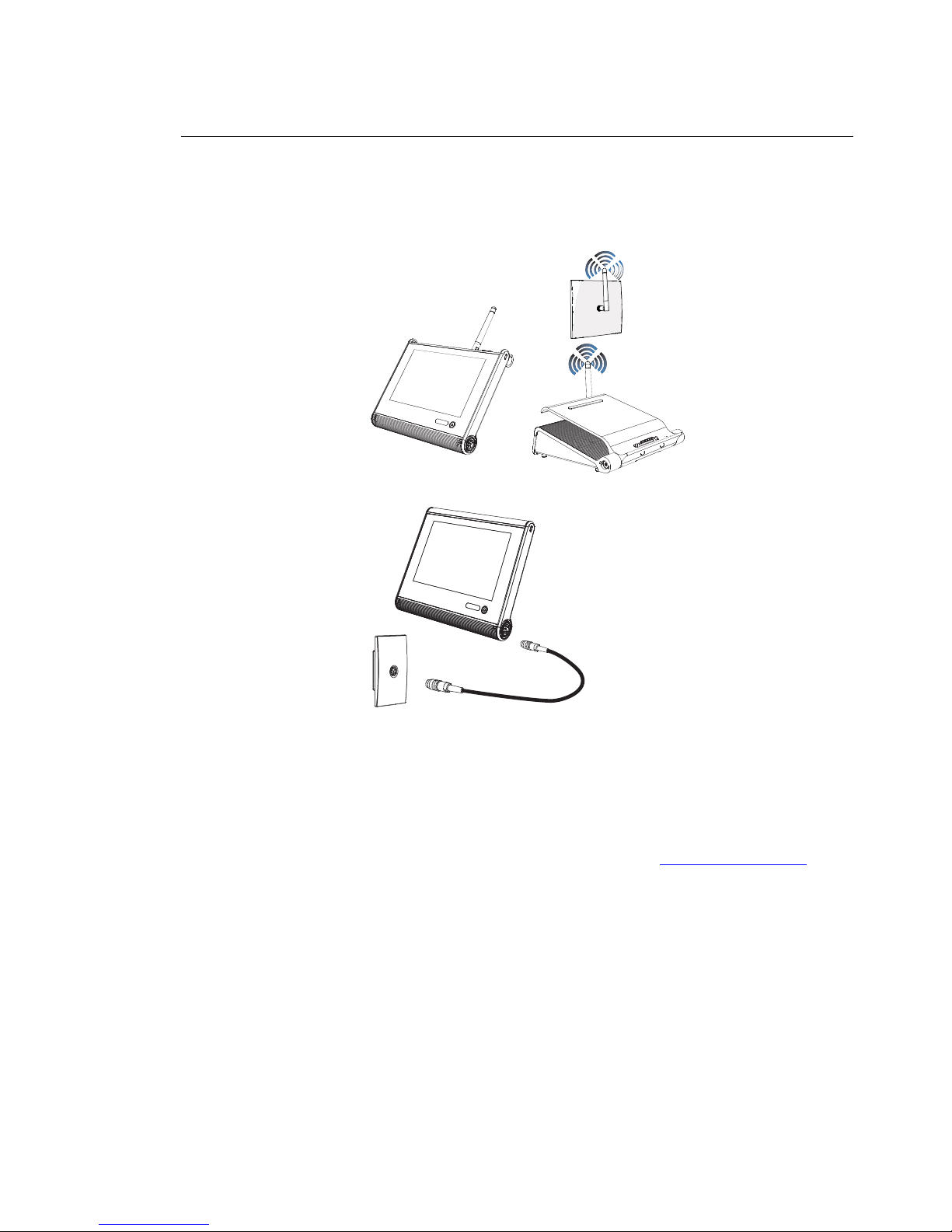
Welcome to the Unison Paradigm Handheld and Wireless Accessories Configuration and
User Manual. This manual contains the procedures for setup of the Paradigm Handheld
Touchscreen as well as configuration of its use with wireless accessories including the
Paradigm Docking Station and Wireless Access Station and its configuration with
LinkConnect accessories including the Unison Portable Connector Station (UH1RS).
Reference the related accessory documentation for more information on installation and
hardware setup:
• Paradigm Wireless Access Station Installation Guide
• Paradigm Docking Station Setup Guide
• Unison Heritage Portable Receptacle Station Installation Guide
Documentation is available for download on the ETC website www.etcconnect.com
.
Wireless Access Station
(P-LCD-WAS)
Docking Station
(P-LCD-DOCK)
Handheld
Touchscreen
Station
(P-LCD-HH)
MeshConnect system
Handheld Touchscreen
Station (P-LCD-HH)
Portable Cable
Unison Portable
Receptacle
Station (UH1RS)
LinkConnect system
Page 6
2 Configuration and User Manual
Document Conventions
These symbols are used throughout this document to alert you to important information.
Contacting ETC
If you are having difficulties configuring your new ETC Handheld Touchscreen, your most
convenient resources are the references given in this user manual. To search more widely,
try the ETC Web site at www.etcconnect.com
. If none of these resources is sufficient,
contact ETC Technical Services directly at one of the offices identified below. Emergency
service is available from all ETC offices outside of normal business hours.
When calling for help, please have the following information available:
• Product model and serial number (located on back panel)
• List of Handheld accessories including Portable Receptacle Station (UH1RS), Docking
Station, Wireless Access Station, etc.
• Paradigm software version
• Other components in your system (Unison
®
, other consoles, etc.)
Please email comments about this manual to: TechComm@etcconnect.com
Note:
Notes are helpful hints and information that is supplemental to the main text.
CAUTION:
A Caution statement indicates situations where there may be undefined or
unwanted consequences of an action, potential for data loss or an equipment
problem.
Americas United Kingdom
Electronic Theatre Controls Inc. Electronic Theatre Controls Ltd.
Technical Services Department Technical Services Department
3031 Pleasant View Road 26-28 Victoria Industrial Estate
Middleton, WI 53562 Victoria Road,
800-775-4382 (USA, toll-free) London W3 6UU England
+1-608 831-4116 +44 (0)20 8896 1000
service@etcconnect.com service@etceurope.com
Asia Germany
Electronic Theatre Controls Asia, Ltd. Electronic Theatre Controls GmbH
Technical Services Department Technical Services Department
Room 1801, 18/F Ohmstrasse 3
Tower 1, Phase 1 Enterprise Square 83607 Holzkirchen, Germany
9 Sheung Yuet Road +49 (80 24) 47 00-0
Kowloon Bay, Kowloon, Hong Kong techserv-hoki@etcconnect.com
+852 2799 1220
service@etcasia.com
Page 7

Handheld Touchscreen and Wireless Accessories User Manual 3
Chapter 1
Overview
The Paradigm Handheld Touchscreen provides flexible control of your Paradigm lighting
control system, wherever it is convenient for you to work in the venue. The Handheld
Touchscreen can be connected to your Paradigm lighting control system using a
LinkConnect wired connection, MeshConnect wireless connection, or docked on the
Paradigm Docking Station.
This chapter contains the following sections:
• Handheld Touchscreen Overview. . . . . . . . . . . . . . . . . . . . . . 4
• Docking Station Overview . . . . . . . . . . . . . . . . . . . . . . . . . . . . 8
• Wireless Access Station Overview . . . . . . . . . . . . . . . . . . . . . 9
• LinkConnect Overview and Setup. . . . . . . . . . . . . . . . . . . . . 10
• MeshConnect Overview and Setup. . . . . . . . . . . . . . . . . . . . 11
• Configuration and Theme Files. . . . . . . . . . . . . . . . . . . . . . . 14
Page 8
4 Configuration and User Manual
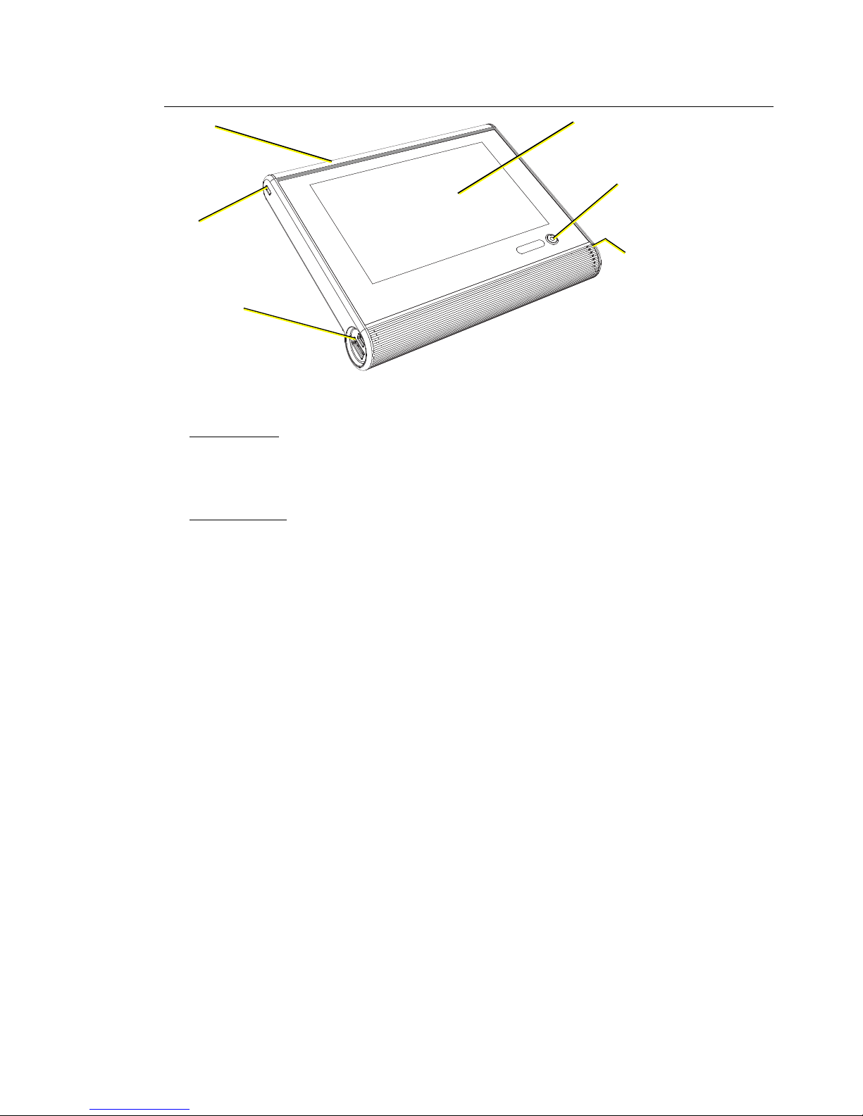
Handheld Touchscreen Overview
Power and Data Connections
LinkConnect
LinkConnect uses Echelon® LonTalk® with LinkPower to connect by cable between the
Handheld Touchscreen and the Paradigm Architectural Control Processor (P-ACP). See
“LinkConnect Overview and Setup” on page 10.
MeshConnect
MeshConnect Uses the Handheld Touchscreen built-in radio to communicate wirelessly
with a Docking Station or Wireless Access Station. See “MeshConnect Overview and
Setup” on page 11.
USB ports
micro USB
USB 2.0
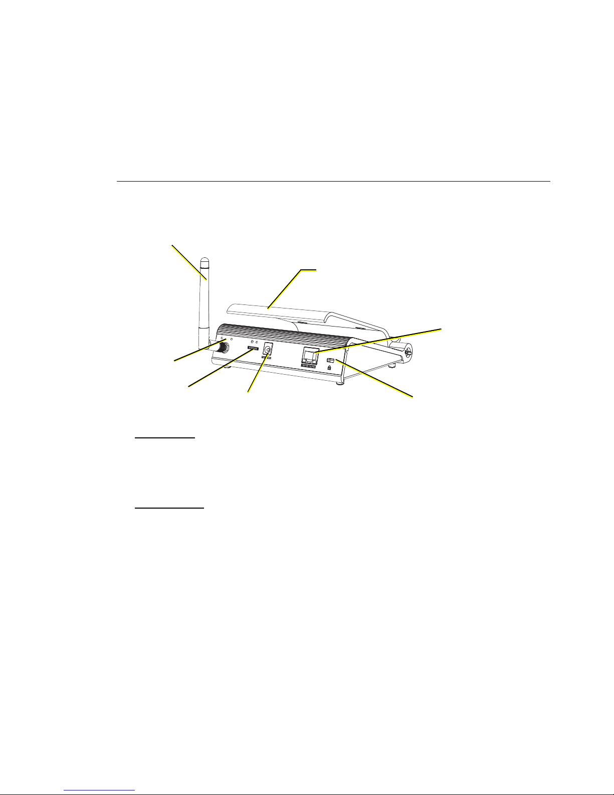
Access Panel
indicators, SD card slot,
MeshConnect, wireless
antenna
7” LCD Touchscreen
WVGA (800x480)
Power /
Navigation
LinkConnect
Portable Cable receptacle
Lock
Page 9
Handheld Touchscreen and Wireless Accessories User Manual 5
Access Panel
Wireless Antenna
Buttons and Indicators
Each of the buttons and indicators on the Touchscreen I/O panel are labeled and grouped
according to their relationship and function.
STATUS
This section includes all buttons and indicators that relate specifically to the Touchscreen
function and features.
• Reset button - when pressed, resets the Handheld Touchscreen software causing a
reboot
• Mode button - press once to access the Setup Menu (see page 18). Press and hold for
four seconds to access the Calibrate Touchscreen feature.
• USB indicator - flashes when the battery charging source is USB
• Aux indicator - illuminates solid when powered by the Docking Station or portable
LinkConnect cable. Alternatively, this LED flashes when the Handheld battery is
charging from these sources.
• Bat indicator - flashes when the battery is charging
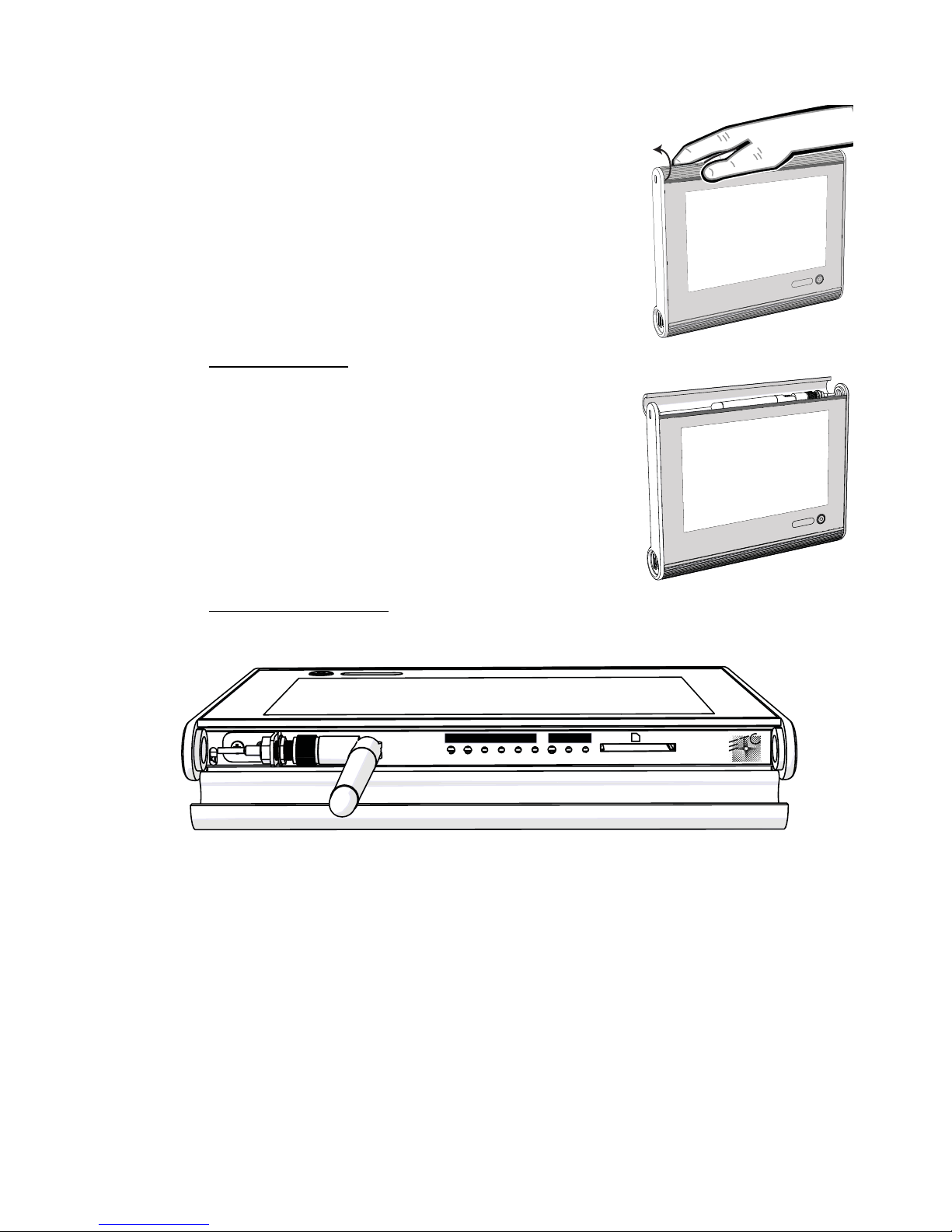
The access panel is located on the top edge of the
Handheld Touchscreen. To open the access panel, place
your thumb on the front of the access panel and wrap your
fingers to the back side. While holding your thumb in
place, apply pressure with your fingers and rotate the
access panel open.
The wireless antenna for the Handheld is located behind
the access panel. The wireless antenna is designed to
operate behind the closed access panel. It is not
necessary to extend the wireless antenna on the
Handheld during operation.
STATUS LON
Reset Mode USB Aux Bat Act Svc Svc Data
Page 10
6 Configuration and User Manual
• Act indicator - flashes to indicated the device is operating normally.
LON
This section includes all buttons and indicators that relate specifically to data use.
• Svc button - sends a service pin message by LinkConnect to the connected processor
• Svc indicator - illuminates solid when a service pin command has been sent to the
processor.
• Data indicator - illuminates (flashing) to indicate transmission of data packets when the
Touchscreen is connected to a processor.
SD Card Slot
• Secure Digital (SD) card slot - this connection is used for local upload and download of
configuration and theme files. The SD card slot supports standard SD and SDHC
cards.
Power/Navigation Button
The “Power” button on the front of the Handheld Touchscreen has multiple functions,
depending on the state the Handheld is in at the time of use.
Power Up
From a powered off state, press the “Power” button one time to power the Handheld
Touchscreen. Application startup can take up to 30 seconds.
Standby/Wake
When the Handheld is powered on, pressing the “Power” button once places the
Touchscreen in standby mode, saving the battery power.
When the Handheld is in standby mode, wake the Touchscreen by pressing the “Power”
button once. The Touchscreen resumes normal operation.
Status Display
When the Handheld is powered on, pressing the “Power” button twice displays status icons
and a soft button in the upper right corner of the Touchscreen. Which icons display are
dependant on the status of the Handheld’s connection and the configuration. Status icons
are defined on the following page.
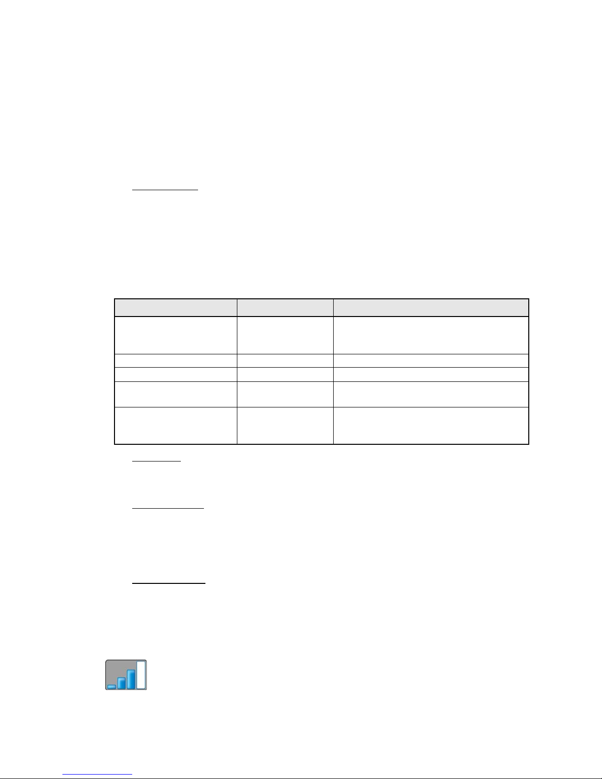
Wireless Signal
• Wireless signal displays on the top left corner of the Touchscree of the current
displayed page. This bar graph displays the wireless signal strength of the connected
device (if any).
Current Handheld State Action Result
Powered Off press power button
Touchscreen powers up (application
loading could take up to 30 seconds to
initialize)
Standby mode press power button Touchscreen wakes to configured page
Normal operation (wake) press power button Touchscreen goes into Standby mode
Normal operation (wake)
double press power
button
Touchscreen displays Status icons and a
soft button
Normal operation (wake)
press and hold
power button for 5
seconds
Touchscreen powers off
Page 11
Handheld Touchscreen and Wireless Accessories User Manual 7
Wireless Status Soft Button
• The top right corner of the Touchscreen displays a soft button which displays as
different icons depending on the current state of the system and how the Handheld is
configured. The Handheld can be configured for Manual or Automatic configuration
selection.
• When the Handheld is setup for “Manual” Wireless Config Selection, you can select
the configuration you wish to connect to from the available configurations in the
“Select Configuration” list. Reference page 16 for more information.
• When the Handheld is setup for “Automatic” Wireless Config Selection, the
Handheld will search and connect to the strongest wireless signal available and
load that associated configuration. Reference page 16 for more information.
Docked
• When the Handheld is docked to a Docking Station, the bottom left corner of the
Touchscreen displays an animated icon representing the Handheld on a Docking
Station.
Battery
• The bottom right corner of the Touchscreen displays a battery level indicator. When the
battery level is high, the indicator displays graduated green levels. When the battery
level is low, the level indicator graduates through amber colors to a flashing red. See
“Charging the Handheld Touchscreen” on page 37.
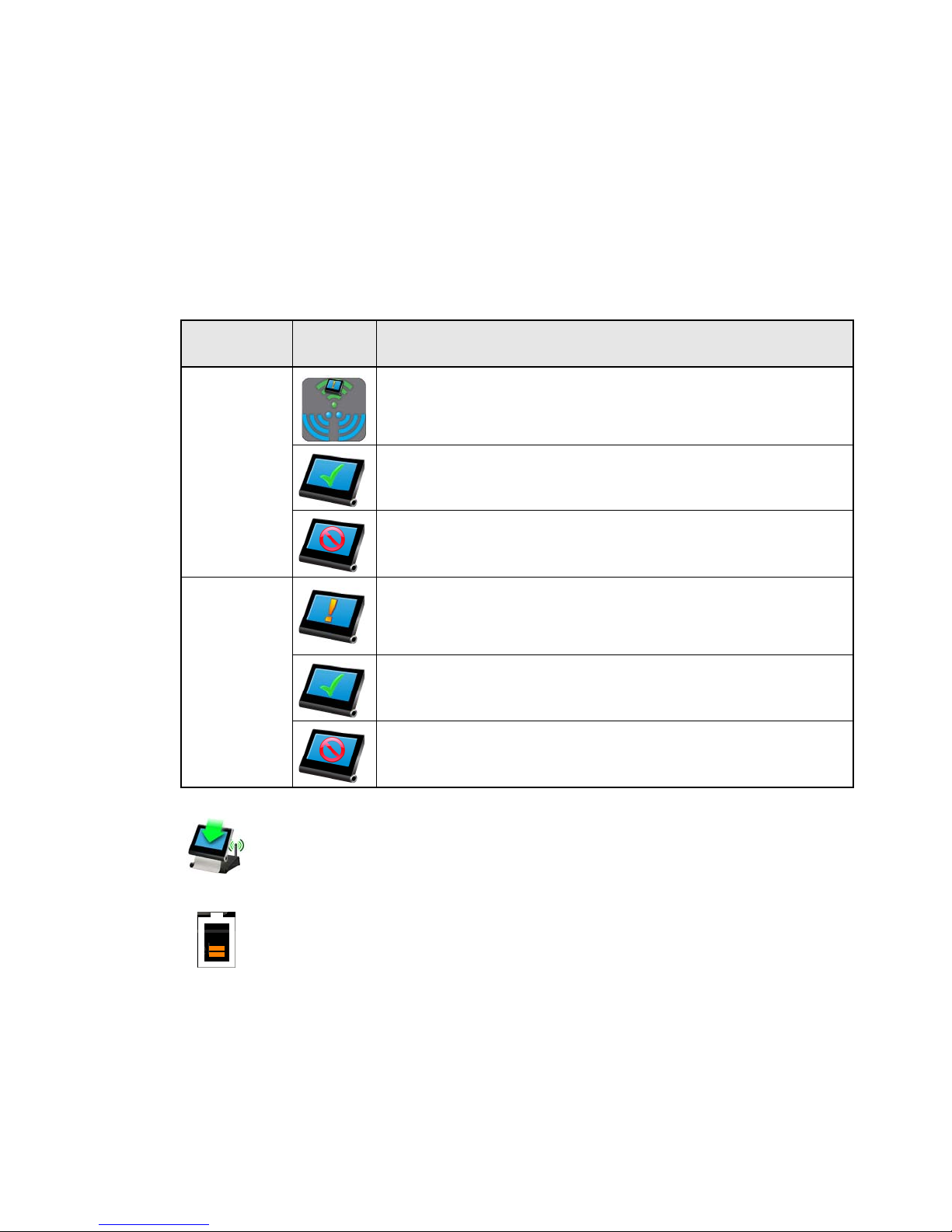
Configuration
mode
Icon Description
Manual
Other configurations available. This icon displays when other
wireless configurations are within range. Press the icon (soft button)
to display the Select Configuration screen, then select the desired
configuration for loading.
Displays when the Handheld is connected to and using the only
available configuration. When this icon displays, there are no other
configurations available for selection.
Configuration unavailable. This icon displays when the Handheld is
not within wireless range of any Wireless Access Station or Docking
Station.
Automatic
Configuration change is pending. This icon displays when a
Handheld is about to load the configuration from another detected
Wireless Access Station or Docking Station that has a stronger
wireless signal.
Displays when a Handheld is connected to and using the only
available configuration or the strongest detected wireless
configuration.
Configuration unavailable. This icon displays when the Handheld is
not within wireless range of any Wireless Access Station or Docking
Station.
Page 12
8 Configuration and User Manual
USB Ports
Two USB ports are located on the bottom left edge of the Handheld Touchscreen.
• USB - this connection is used for local upload and download of configuration and theme
files using USB removable media.
• micro USB - this connection is used for charging the Handheld from a USB power
adapter. See “Charging using Micro USB Power Supply” on page 37.
Docking Station Overview
The Docking Station connects to the Paradigm control network using Ethernet or
NetConnect (Power over Ethernet 802.3af) and serves the Handheld Touchscreen as both
a table top charging station and a wireless access point for MeshConnect communications.
NetConnect
NetConnect uses Power over Ethernet (IEEE 802.3af) communications to connect between
the Paradigm Docking Station and the Paradigm Architectural Control Processor (P-ACP).
A 12V DC power input adapter is supplied and can be used when Power over Ethernet is
not available.
MeshConnect
MeshConnect Uses the built-in radio to communicate wirelessly with the Handheld
Touchscreen Station. See “MeshConnect Overview and Setup” on page 11.
Reference the Paradigm Docking Station Setup Guide for more information.
R
x
T
x
R
e
s
e
t
P
w
r
MeshConnect
antenna
RX and TX
Indicators
DC Power input
12V Input
Lock
NetConnect
Adjustable
Cradle
Reset button
Power indicator
Page 13

Handheld Touchscreen and Wireless Accessories User Manual 9
Wireless Access Station Overview
The Wireless Access Station connects to the Paradigm control network over LinkConnect
and serves the Handheld Touchscreen as a wireless access point for MeshConnect
communication.
LinkConnect
LinkConnect uses Echelon® LonTalk® with LinkPower to connect by cable between the
Wireless Access Station and the Paradigm Architectural Control Processor (P-ACP). See
“LinkConnect Overview and Setup” on page 10.
MeshConnect
MeshConnect uses the Handheld Touchscreen built-in radio to communicate wirelessly
with a Wireless Access Station. See “MeshConnect Overview and Setup” on page 11.
Reference the Paradigm Wireless Access Station Installation Guide for more information.
Page 14
10 Configuration and User Manual
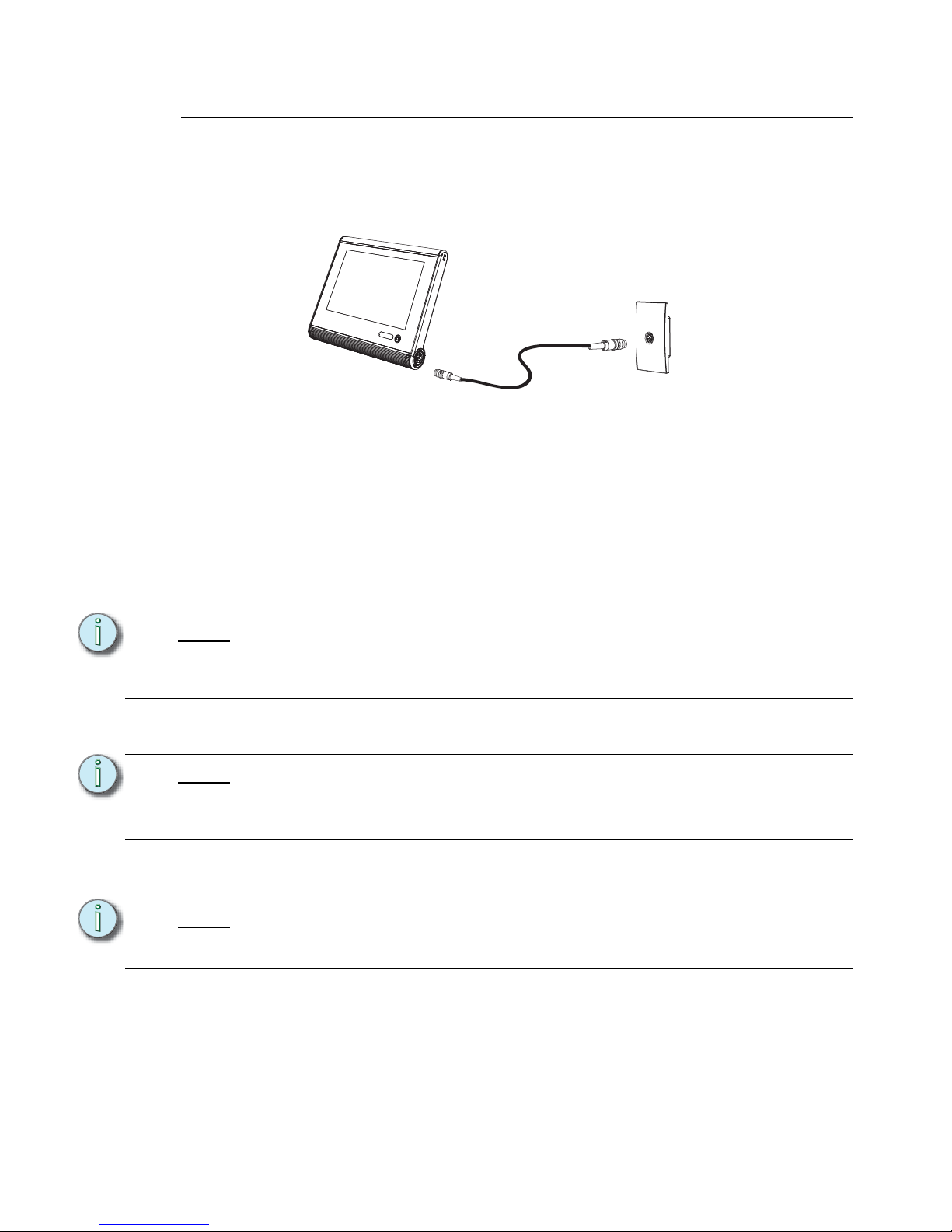
LinkConnect Overview and Setup
For the Handheld Touchscreen to use both power and control over the LinkConnect
network, connect a LinkConnect Portable Cable between the Handheld Touchscreen and
an installed Unison Heritage Portable Receptacle Station (UH1RS).
Installation and Configuration Requirements
Prior to connecting your Handheld Touchscreen using LinkConnect, please confirm the
installation meets the following requirements:
• All components used, including the Unison Heritage Portable Receptacle Stations and
the Handheld Touchscreens, must exist in the LightDesigner configuration.
• The “Portable Wired” property of the Handheld Touchscreen station is configured within
the LightDesigner Property Editor for use with the Portable Receptacle Station.
• The Unison Heritage Portable Receptacle Station Neuron ID (labeled on the front of the
station with the cover removed) is associated to the configured station in LightDesigner.
• The LightDesigner configuration should be uploaded to the connected Paradigm
Architectural Control Processor(s).
Note:
A Handheld Touchscreen can be associated to multiple Portable Receptacle
Stations within a configuration. The displayed configuration and theme may be
different for each configured Handheld Touchscreen and portable receptacle
station depending on the assignments in the configured space.
Note:
If the ID is not entered into the LightDesigner configuration, the station must be
manually connected (bound) at the Paradigm Architectural Control Processor (PACP). When manual binding is required, reference the Paradigm Architectural
Control Processor Configuration Manual.
Note:
Information related to LightDesigner software including configuration, upload, and
associating Neuron/ROM IDs, can be found in the LightDesigner online help
system.
Handheld
Touchscreen Station
(P-LCD-H)
LinkConnect
Portable Cable
Unison Portable
Receptacle
Station (UH1RS)
LinkConnect system
Page 15

Handheld Touchscreen and Wireless Accessories User Manual 11
MeshConnect Overview and Setup
MeshConnect is the wireless control network used with the Handheld Touchscreen for
communication with a Docking Station or Wireless Access Station.
Wireless communications uses Zigbee wireless communication radio (IEEE 802.15.4).
Power for the Handheld unit is provided from the built-in rechargeable battery. You will need
to fully charge the unit before use. Reference Charging the Handheld Touchscreen, page
37.
Installation and Configuration Requirements
Prior to connecting your Handheld Touchscreen using MeshConnect, the following
requirements must be met:
• All components used including the Handheld Touchscreens, Docking Stations and
Wireless Access Stations must exist in the LightDesigner configuration.
• All station Neuron IDs should be added to the LightDesigner configuration.
• The LightDesigner configuration should be uploaded to the connected Paradigm
Architectural Control Processor(s).
• Docking Stations have been assigned compatible IP Addresses. Reference page 13 for
instructions to assign the IP Address.
• The Docking Station must also be associated by Neuron ID to the configured device in
LightDesigner. The Neuron ID is available from the Dock (see page 33) tab in the Setup
menu when a Handheld Touchscreen is docked. It can also be found on the product
label or from the Network view of LightDesigner.
• The “Wireless” property of the Handheld Touchscreen station is configured within the
LightDesigner Property Editor for use with the wireless accessory.
• The Wireless HF Channel property for all wireless devices must match. By factory
default this setting is HF Channel 10.
• To configure the HF Channel property for the Handheld Touchscreen, reference
Select HF Channel, page 23.
• To configure the HF Channel for the Docking Station and Wireless Access Station,
reference the Paradigm Architectural Control Processor Configuration Manual or
reference the LightDesigner online help system.
Note:
A Handheld Touchscreen can be associated to multiple Docking Stations and/or
Wireless Access Stations within a configuration. The displayed configuration and
theme may be different for each configured Handheld Touchscreen based on
which Dock or Access station it is connected.
Information related to LightDesigner software including configuration, upload, and
associating Neuron IDs, can be found in the LightDesigner online help system.
Or
Page 16

12 Configuration and User Manual
Setup and Connect
Step 1: Fully charge the Handheld Touchscreen before using with a MeshConnect
control system. Reference Charging the Handheld Touchscreen, page 37 for
instructions.
Step 2: Press the “Power” button once on the front of the Handheld. Application startup
takes a minimum of 20 seconds.
Step 3: Which configuration is loaded to the Handheld depends on the Wireless Config
Selection (see page 25) setting, either Automatic Wireless Config Selection or
Manual Wireless Config Selection. This setting is “Automatic” by default.
Automatic Wireless Config Selection
When the Handheld is setup for Automatic Wireless Config Selection, the Handheld will
search and connect to the strongest wireless signal available and load that associated
configuration.
• During normal use, when another configuration within range of the Handheld is
stronger the Wireless Status icon displays. This icon means a configuration
change is about to occur.
• The configuration will change automatically within several seconds of the configuration
change notification. You can postpone the configuration change for 2 minutes by
touching the Wireless Status soft button, then choosing cancel from the Automatic
Selection screen.
Manual Wireless Config Selection
When the Handheld is setup for Manual Wireless Config Selection, select the configuration
you wish to connect to from the available configurations in the Select Configuration list.
• During normal use, when another configuration becomes available to the Handheld, a
Wireless Status icon displays. This icon means that additional wireless
configurations are available for selection to the Handheld. Touch the Wireless Status
soft button to display the Select Configuration screen.
Note:
If the Handheld does not have the configuration and theme file, you will be
provided the option to download the files from the connected processor. The most
efficient method to load configuration and theme files is to use removable media.
See “Configuration and Theme Files” on page 14.
Page 17

Handheld Touchscreen and Wireless Accessories User Manual 13
Connecting wirelessly to a Docking Station or Wireless Access Station
When connected wirelessly to a Docking Station or Wireless Access Station, the Handheld
Touchscreen loads the associated configuration for that station. Configurations can be
shared among the wireless devices, but each station can have only one configuration
associated.
When using a Docking Station, the dock must be assigned a valid IP Address to
communicate with the Paradigm control system.
Assign an IP Address for a Docking Station:
Step 1: Connect the Docking Station to the lighting control network following the
instructions provided in the Paradigm Docking Station Setup Guide.
Step 2: Power on the Handheld Touchscreen, then dock it to the Docking Station.
Step 3: Press the [Setup] button on the Touchscreen. The Setup “About” screen
displays.
Step 4: Press the [Dock] tab. The passcode keypad displays.
Step 5: Enter the setup or admin passcode. By factory default, the setup passcode is set
to 3031. The “Dock” configuration page displays.
Step 6: Reference the Dock configuration section on page 33 for information to assign
the IP Address.
The Handheld Touchscreen and each configured wireless accessory must use the same
HF Channel for communication. Configuration of the HF Channel for each device is slightly
different.
Configure the HF Channel for the Handheld Touchscreen
Reference Radio Options on page 23 for instructions to change the HF Channel and other
radio specific options on the Handheld Touchscreen.
Configure the HF Channel for the Wireless Accessories
From the Paradigm Architectural Control Processor (P-ACP)
Step 1: Navigate to the Arch Setup > Lonworks Connections menu.
Step 2: Select Wireless HF Channel.
Step 3: Select the wireless device from the list for configuration.
Step 4: Select the desired HF Channel. Available settings are HF Channel 1 through HF
Channel 12.
Docking a Handheld Touchscreen to a Docking Station
When the Handheld Touchscreen is docked to a Docking Station, the Handheld
Touchscreen loads the associated configuration for that Docking Station. Automatic and
Manual configuration selection is not available when the Handheld is docked.
Note:
Once the Docking Station has been assigned a valid IP Address, it is ready for use
in the system. Any future connection of the Handheld to the Docking Station will
behave as described in the Wireless Config Selection setting (see page 25).
Note:
The Wireless HF Channel can also be configured from LightDesigner.
CAUTION:
Be sure each wireless device HF Channel is the same or they will not
communicate. This includes Handheld Touchscreens docked to Docking Stations.
Page 18

14 Configuration and User Manual
Configuration and Theme Files
Configuration and theme files are stored and recalled locally from the Touchscreen. Each
configuration and theme that will be used on the Touchscreen must be loaded once during
setup or when the configuration or theme is modified.
When a Handheld Touchscreen is connected to the system and it does not have the
associated configuration and theme file for recall, the Touchscreen will prompt to begin
downloading the associated files. When connected wirelessly it is recommended that you
manually load the configuration files using removable media instead. File transfer over a
wireless connection can be slow.
Retrieve the Configuration and Theme Files
Configuration and theme files are available from the Paradigm Architectural Control
Processor (P-ACP) or from within the LightDesigner configuration.
Retrieve from the P-ACP
Step 1: Insert removable media into the Paradigm Architectural Control Processor, either
USB or SD media.
Step 2: Navigate to File Operations from the main menu.
Step 3: Select Save LCD Files.
Step 4: Select the desired configuration file from the available configurations in the list.
Step 5: Select the media type for the save operation. Two files types will be exported; the
configuration file saves with a “*.lcdconf” extension and the theme saves with an
“*.lcdtheme” extension.
Retrieve from LightDesigner
Step 1: From the LightDesigner configuration, select “Extract Portable Touchscreen
Files” from the (Project) menu. The Extract Portable Touchscreen Files dialog
displays.
Step 2: Select which Portable Touchscreen files will be exported from the selection and
click [OK]. The Browse For Folder dialog displays for selection of a location the
files will be exported to, such as a removable USB device. Two files types will be
exported; the configuration file saves with a “*.lcdconf” extension and the theme
saves with an “*.lcdtheme” extension.
Loading Files to the Touchscreen
Step 1: Insert the removable media into the appropriate location, SD or USB.
• USB media is located on the bottom left edge of the Handheld.
• SD media port is located behind the Access Panel.
Step 2: Access the Setup menu by pressing the [Setup] button on the display or by
pressing the Mode button (page 5) located behind the Access Panel. The display
changes to the “About” tab of the Setup menu.
Step 3: Press the [Files] button. A keypad displays for passcode entry.
Step 4: Enter the four digit setup or admin passcode _ _ _ _ to access the “Files” menu.
By factory default, this setup passcode is 3031.
Step 5: Press the [Config] button to load the configuration file(s) or press [Theme] to
load theme file(s) to the Touchscreen.
Page 19

Handheld Touchscreen and Wireless Accessories User Manual 15
Step 6: Press [Load From] and choose the removable media source the configuration
files will be loaded from, then press [OK].
Step 7: Select the specific file (or select multiple files) from the list that you would like to
load onto the Touchscreen.
Step 8: Press [OK]. The selected files will save to the selected media.
Note:
Standard ETC provided themes used in your configuration do not need to be
manually loaded to the LCD. These themes are loaded for you at the factory and
will display beneath the “Themes” directory.
Page 20

16 Configuration and User Manual
Configuration Selection
The Handheld Touchscreen can be configured to automatically change the configuration
depending on the strongest wireless signal or for manual configuration selection by a user.
By default, the Handheld Touchscreen is set to Automatic Config Selection.
Modes and Use
Power-up behavior depends on whether the Handheld is setup for Automatic or Manual
configuration selection.
Automatic Config Selection
When the Touchscreen is powered-up, it begins the search for all wireless signals
connected in the system. The Touchscreen will automatically connect to the strongest
wireless signal detected. After connecting, the Touchscreen will begin loading the
associated configuration.
Manual Config Selection
On power up, the Touchscreen displays the “Select Configuration” page. Access to the
“Select Configuration” page is also possible anytime by touching the Wireless Status soft
button. This page includes a listing of all wireless devices, such as Docking Stations and
Wireless Access Stations, that have configurations that can be loaded to the Touchscreen
as well as access to the Setup Menu.
Note:
All wireless devices must be on the same HF Channel to communicate. Reference
the Paradigm LightDesigner online help system or the Paradigm Architectural
Control Processor Configuration Manual for information to change the HF
Channel in Handheld Touchscreen wireless accessory products.
Note:
If the Handheld does not have the configuration and theme file, you will be
provided the option to download the files from the connected processor. The most
efficient method to load configuration and theme files is to use removable media.
See “Configuration and Theme Files” on page 14.
Page 21

Handheld Touchscreen and Wireless Accessories User Manual 17
Each wireless device in the list also displays the name of the associated configuration and
a bar graph indicating the wireless signal strength for that device. Select an access point
from the list and press the [Connect] button to load the specified configuration for that
wireless device.
From this page you can also access the “Setup Menu (see page 18)” by pressing the
[Setup] button.
Note:
If the Handheld does not have the configuration and theme file, you will be
provided the option to download the files from the connected processor. The most
efficient method to load configuration and theme files is to use removable media.
See “Configuration and Theme Files” on page 14.
Page 22

18 Configuration and User Manual
Chapter 2
Setup Menu
Pressing the [Setup] button or pressing the “Mode” button Buttons and Indicators on page
5displays the Setup menu.
This chapter contains the following sections:
• About . . . . . . . . . . . . . . . . . . . . . . . . . . . . . . . . . . . . . . . . . . . . 19
• Screen . . . . . . . . . . . . . . . . . . . . . . . . . . . . . . . . . . . . . . . . . . . 20
• Sound. . . . . . . . . . . . . . . . . . . . . . . . . . . . . . . . . . . . . . . . . . . . 21
• Comms. . . . . . . . . . . . . . . . . . . . . . . . . . . . . . . . . . . . . . . . . . . 22
• Config . . . . . . . . . . . . . . . . . . . . . . . . . . . . . . . . . . . . . . . . . . . 26
• Protected Features and Tabs . . . . . . . . . . . . . . . . . . . . . . . . 27
• Files . . . . . . . . . . . . . . . . . . . . . . . . . . . . . . . . . . . . . . . . . . . . . 31
• Dock. . . . . . . . . . . . . . . . . . . . . . . . . . . . . . . . . . . . . . . . . . . . . 33
• System . . . . . . . . . . . . . . . . . . . . . . . . . . . . . . . . . . . . . . . . . . . 34
Page 23

Handheld Touchscreen and Wireless Accessories User Manual 19
About
The About tab displays read-only information pertaining to the Handheld Touchscreen
including;
• Neuron Id: a station specific unique hardware address that is permanent to the
Touchscreen. This ID is used by the Paradigm Architectural Control Processor to bind/
associate (bind) stations within the LightDesigner configuration.
• Bootloader: the bootloader software version.
• Firmware: the application firmware version loaded onto the Touchscreen. Firmware
can be updated, reference System on page 34 for instructions.
• Memory Usage Total: a Paradigm Touchscreen has 128 megabytes (Mb) of memory
available for configuration storage. The “Memory Usage” section displays the “Total”
memory available, the memory “Used” and the available memory that is “Free” for use.
• Boot Reason: the last action that caused the Touchscreen to boot. Reasons for reboot
could be due to a [Reset] button press on the Touchscreen I/O panel, power loss, etc.
• Watchdog: the status of the Watchdog tool.
• Battery: the level of current battery charge (0-100%)
• WBS Type: the wireless base station device type that the Handheld is currently
connected. If the Handheld is not currently connected to a wireless device, “Not
Connected” will display.
• WBS Version: the version of software running on the wireless base station device that
the Handheld is currently connected to. If the Handheld is not connected to a wireless
device, N/A will display.
• Local storage: displays the internal memory in use and in relation to the capacity in the
device.
Page 24

20 Configuration and User Manual
Screen
The Screen tab provides user settings for the Handheld Touchscreen including:
• Backlight Level: a level bar is provided to set the relative brightness of the Touchscreen
backlight. By default, the level is set to full.
• Backlight Timeout: sets the length of inactivity time before the backlight fades to its
backlight timeout level. This is separate from any configuration related Inactivity
Timeout settings.
• Backlight Timeout Level: the intensity level the backlight will fade to when its “Backlight
Timeout” has been reached. This level can be set to either “Off” or “Dim”.
• Light Sensor: allows the Touchscreen to determine an appropriate Backlight Level
based on ambient light in the space. The internal light sensor measures the ambient
light and adjusts the backlight proportionally based on the established backlight level
settings. By default, the light sensor is “Off”.
• Inactivity Battery Saver: allows the Touchscreen save battery power by going into
Standby mode after a specified period of inactivity. Options include Never, 30 mins, 1,
2, 4, 6 or 8 hours. The default setting is 2 hours.
• Local Storage: displays the internal memory in use and in relation to the capacity in the
device.
Note:
When the Light Sensor is “On”, the backlight level sets the maximum level of
brightness.
Page 25

Handheld Touchscreen and Wireless Accessories User Manual 21
Calibrate Touchscreen
The Screen tab provides a [Calibrate Touchscreen] button that when pressed, launches
the calibration display. This display is provided as a tool for recalibrating the touch
behaviors on the Touchscreen.
Calibration may be required if presses on the Touchscreen are recognized in an area other
than where the screen was pressed.
To calibrate the Touchscreen, simply touch as close to the center of the “+” symbol as it is
displayed. The “+” symbol will move to five separate coordinates on the touchscreen to
complete the calibration.
When all five coordinates have been calibrated, press [Close] to return to the previously
displayed page. If you are unsatisfied with the calibration results, press [Recalibrate] to
start the calibration again or press [Clear] to clear your settings.
Sound
The Sound tab provides a volume control for the master volume level of the Touchscreen’s
built-in speakers.
Note:
Pressing and holding the [Mode] button (located behind the Access Panel of the
Touchscreen) for four seconds launches the calibration display.
Page 26

22 Configuration and User Manual
Comms
The Comms tab provides communication settings and information including which
Paradigm Architectural Control Processor (P-ACP) the Touchscreen is connected to, and
provides access to the wireless connectivity features.
• Server Name: this is the name of the Paradigm Architectural Control Processor that the
Touchscreen is connected to (P-ACP).
• Connection Type: this is the type of connection that is made to the P-ACP. Connection
types include Wireless, High Speed Serial Dock (+Wireless), or LinkConnect (Lon), or
None.
• Wireless Config Selection: this allows selection of either Automatic or Manual
configuration mode and identifies the active configuration, if any. Reference Wireless
Config Selection, page 25.
• Local Storage: displays the internal memory in use and in relation to the capacity in the
device.
Page 27

Handheld Touchscreen and Wireless Accessories User Manual 23
Radio Options
To change the Handheld Touchscreen HF Channel, set the Automatic Selection Threshold,
and access the HF Channel Energy Scan, press the [Radio Options] button.
Select HF Channel
The Paradigm Handheld is set to HF Channel 10 by factory default. To change the
Handheld from its default setting, touch the [10
▼] button in the selection field. Available
options include HF Channels 1 through 12.
Determining which HF Channel to use is simplified when you use the "HF Channel Energy
Scan".
Note:
All wireless devices must be on the same HF Channel to communicate. Reference
the Paradigm LightDesigner online help system or the Paradigm Architectural
Control Processor Configuration Manual for information to change the HF
Channel in Handheld Touchscreen wireless accessory products.
Page 28

24 Configuration and User Manual
Automatic Selection Threshold
This setting allows you to specify the wireless signal strength (in dBm) before a
configuration change occurs when your "Wireless Config Selection" is set to Automatic. As
a wireless signal weakens the Handheld Touchscreen will search the area for a stronger
signal.
Use the slide bar to set the threshold in dBm. By default this value is set to 15 dBm.
HF Channel Energy Scan
Use the HF Channel Energy Scan to determine which HF Channel offers the best
opportunity for successful wireless signal and range for the Handheld Touchscreen and
wireless accessories.
Press the [HF Channel Energy Scan] button to begin the scan.
The display changes to a bar graph, representing all 12 Channels available to the Handheld
Touchscreen. The current channel in use is highlighted in yellow. Select the button beneath
the bottom of a channel to make a new channel selection.
The bar graph constantly updates with the most recent scanned channel data. The bar
graph data offers both a color code and a numeric reference for determining the best
channel for wireless communication.
• When an HF Channel has low traffic, the bar graph will indicate a small green bar. This
is the optimal channel selection for the Handheld Touchscreen and its wireless
accessories.
• When the HF Channel has moderate traffic, the bar graph will indicate a blue bar. This
channel selection is acceptable for the Handheld Touchscreen and its wireless
accessories when no other channel is available.
• When the HF Channel has high traffic, the bar graph will indicate a larger yellow or red
bar. These channels should be avoided.
Note:
Higher values require larger differences in signal strengths before the
configuration change will occur. For example, if the Handheld is connected to a
Wireless Access Station and that station signal is currently at -45 dBm; the
Automatic Selection Threshold is set to 15 dBm; then the Handheld would need to
discover another wireless signal that is at least -30 dBm to change.
Page 29

Handheld Touchscreen and Wireless Accessories User Manual 25
Wireless HF Power
Wireless HF Power is the power that the Handheld Touchscreen antenna is currently using.
By default, this is set to 10 dBm. Selection is available up to 18 dBm. The higher the power,
the stronger the wireless signal range will be for the Handheld Touchscreen.
When increasing Handheld power, also increase the Wireless Access Station and/or
Docking Station power using LightDesigner. The values should match the Handheld so
bidirectional communication will always be possible.
Wireless Config Selection
Configure the Handheld Touchscreen to wait for a manual configuration selection when a
wireless signal is connected or automatically select the configuration for loading. By default,
the Handheld is set to Automatic configuration selection.
The Handheld Touchscreen by default automatically selects the assigned configuration
based on the wireless device it receives the strongest signal from.
Automatic
Selecting Automatic allows the Handheld Touchscreen to select a configuration
automatically based on signal strength.
Manual
Selecting Manual allows the user complete control over when to switch configurations.
Page 30

26 Configuration and User Manual
Site Survey
The site survey feature is useful to help a user better gauge coverage, whether to ensure
coverage overlap or trying to avoid it. To view a read only list of unbound but powered
wireless accessories that are on the same HF Channel as the Handheld Touchscreen,
select the [Site Survey] button.
The list automatically refreshes with new data and displays the wireless device with the
strongest signal at the top of the list and the weakest at the bottom. Each listed device
includes a bar graph representing the signal strength of each wireless accessory and
includes the raw data in parenthesis next to the device name.
Config
The Config tab displays the project information that was provided in ControlDesigner.
Project information can only be modified in ControlDesigner when the configuration is not
an Automated configuration generated by LightDesigner using the “Automatic Touchscreen
Configuration feature.
Note:
All Paradigm wireless signals that are detected on the same HF Channel will
display in this list, even if the devices are not yet bound within the configuration.
Page 31

Handheld Touchscreen and Wireless Accessories User Manual 27
Protected Features and Tabs
The “Files”, “Network” and “System” tabs as well as the Timed Events and “Passcodes”
features on the Config tab are protected by a passcode and should be used only by trained
personnel. Typically these displays are accessed only during system commissioning.
Pressing any of the tab names will display a keypad for setup or admin passcode entry.
Timed Events
The “Timed Events” button on the Config tab allows users to add and edit Timed Events.
Press the [Timed Events] button on the Config tab, and enter the passcode to begin. All
created timed events will display in the “Timed Event Setup” menu. From this menu you can
add new events, or delete or edit existing events in the list.
Note:
Enter your four digit passcode _ _ _ _ to access these menus. These protected
tabs and features should be accessed only by trained personnel.
Note:
ControlDesigner provides a page navigation action to reach a Timed Event
configuration directly. Use this feature to provide access for users who wish to edit
Timed Events.
Note:
When there is no configuration active, the [Timed Events] and [Passcodes]
buttons are disabled.
Page 32

28 Configuration and User Manual
Adding a new event and editing an event are similar in process.
Add Event
Step 1: Press the [Add] button, a “New Timed Event” configurator displays.
Step 2: Specify the “Start Time”. Pressing the default [Time of Day] button displays a list
of available start times including; “Time of Day”, “Sunrise”, and “Sunset”. Press
to select the option. Depending on the selection, additional options may display:
• If “Time of Day” is selected, additional selection for a “Start Time” is required.
• If “Sunrise” or “Sunset” are selected, additional selection for an “Offset” is
required. An offset is specified as an positive (press the [+] button) or
negative (press the [-] button) hour and minutes setting from the
astronomical time.
Page 33

Handheld Touchscreen and Wireless Accessories User Manual 29
Step 3: Specify the “End Time”. The options for “End Time” are similar to the “Start Time”
except “Duration” is now an option. When “Duration” is the selected “End Time”,
you will also be required to specify the hours and minutes the event should run
from its start time.
Step 4: If an override has been created for the Timed Event, select the override from the
options. For more information regarding overrides, please reference the
Paradigm LightDesigner online help system or contact ETC Technical Services.
Step 5: Press [Next] to specify the Recurrence settings of the Timed Event.
Step 6: Select the “Recurrence Type” from the options available.
• Additional settings are provided depending on the “Recurrence Type” selected. For
example, if “Weekly” is selected, the following options display for selection:
Page 34

30 Configuration and User Manual
Step 7: Press [Next] then select the drop down selection located next to “Start Action” to
display available options.
Step 8: Press to select the option from the list. Notice the ability to scroll to more options
using the scroll bar on the right. Depending on the selection, more options may
display for setting on the “Start Action” page. Complete the options as required.
Step 9: Press [Next] then select the drop down selection located next to “End Action” to
display available options.
Step 10: Press to select the option from the list. Notice the ability to scroll to more options
using the scroll bar on the right. Depending on the selection, more options may
display for setting on the “End Action” page. Complete the options as required.
Passcodes
Passcodes that are assigned in ControlDesigner software for the active configuration are
available for read-only reference on the Handheld Touchscreen using the [Passcodes]
feature.
Page 35

Handheld Touchscreen and Wireless Accessories User Manual 31
Step 1: Press the [Passcodes] button to view the list of passcodes associated to the
active configuration. The keypad for passcode entry displays.
Step 2: Enter your four digit passcode _ _ _ _ to access the passcodes list. All passcodes
for the active configuration display for reference. This is a read-only list.
Files
The Files tab allows you to view, modify, and delete the configuration and theme files that
are currently loaded on the Touchscreen. Access for uploading and downloading the
configuration and theme files from/to removable media such as an SD card or USB key is
also available from the Files tab. See “USB Ports on page 8” and SD Card Slot on page 6.
Note:
When there is no configuration active, the [Timed Events] and [Passcodes]
buttons and features are disabled.
Note:
If the Paradigm Touchscreen is already associated with a Paradigm Architectural
Control Processor (P-ACP), it will automatically begin retrieving its LCD
configuration file when powered.
Standard ETC provided themes are loaded for you at ETC and will display
beneath the “Themes” directory.
Page 36

32 Configuration and User Manual
Saving and Loading Configuration and Theme Files
Step 1: To begin, you must have an USB key or SD card (your choice) inserted into the
Handheld Touchscreen.
Step 2: Select either [Config] or [Theme], whichever file type you want to transfer.
Step 3: If saving a file to removable media select the file from the list and press [Save
to]. If loading a file from removable media, press [Load From].
Step 4: Choose the removable media (SD or USB) you are transferring to/from.
Step 5: Navigate the file structure of the removable media to select the location you are
saving to/loading from. To return to a previous directory in the removable media,
press the [Up] button. Press [Ok] to set the directory location.
Note:
Multiple files can be selected for upload or download by simply touching to select
each file. When a file with the same name exists at the save to location or if it
already exists on the Touchscreen when loading from removable media, you will
be prompted to either [Cancel] the action or [Overwrite] the existing conflicting
file.
Page 37

Handheld Touchscreen and Wireless Accessories User Manual 33
Dock
The Dock tab is available only when the Handheld Touchscreen is docked to the Docking
Station.
The Dock tab provides access to view and edit the network settings for the Docking Station.
In addition, this tab is the only place to access the Docking Station Neuron ID.
IP Addressing
Two “IP Addressing” modes are available for use with the Docking Station; Manual and
Automatic.
• Manual - in manual address mode the IP address and settings are user configured. To
change any portion of the address, simply touch inside the field you wish to modify. A
numeric keypad will display for edit of the selected field. Make the modifications to the
selected field then select another field for edit as necessary. Pressing [Ok] saves your
changes, exits the Setup Menu and returns the display to the previous displayed page.
• Automatic Mode - in automatic mode, the Docking Station is configured to obtain an IP
address and other network settings automatically from a connected DCHP server. The
Handheld Touchscreen will display the Docking Station current settings provided from
the connected DHCP server but the settings are not user editable. If no DHCP server
is present, the Docking Station will assign itself a link-local address in the default
169.254.x.x range. Pressing [Ok] saves your changes, exits the Setup Menu and
returns the display to the previous displayed page.
Neuron ID
The Docking Station Neuron ID displays at the bottom of the Dock tab. This Neuron ID is
required when binding the Docking Station to the Paradigm Architectural Control Processor
(P-ACP).
Note:
Docking Stations must have valid IP Addresses to communicate with the lighting
control system.
Page 38

34 Configuration and User Manual
System
With the exception of battery information, the information displayed on this tab is primarily
of interest to ETC Technical Services for troubleshooting. Additional features of this tab
includes the ability to Reload Firmware, Reset to Defaults, and view the Event Log.
System
The system information displayed relates specifically to the Handheld Touchscreen
hardware.
• Board Revision - the Touchscreen hardware circuit board revision.
Co-Processor
The co-processor provides information that relates to the Handheld Touchscreen processor
and system software.
• Bootloader: the Touchscreen bootloader version.
• Firmware: the Touchscreen firmware version.
Battery
The battery information displayed is specific to the Handheld Touchscreen battery.
• Charge Level: the amount of current charge
• Temperature: the current temperature of the battery
• Voltage: the current voltage output of the battery
• When the Handheld Touchscreen is charging, “Charging” status will display
Page 39

Handheld Touchscreen and Wireless Accessories User Manual 35
Reload Firmware
The [Reload Firmware] button is provided as a tool to load new firmware to the Handheld.
Firmware is loaded to the Handheld Touchscreen from removable media.
Step 1: Insert the USB key or SD card, with the firmware files saved, into the port on the
Touchscreen.
Step 2: Press the [Reload Firmware] button.
Step 3: Select the removable media type (USB or SD) from the recognized installed
media.
Step 4: Select the “PLCD_fw_x.x.x.tfw” file (x = version) from the list. When the firmware
file completes loading, the Touchscreen will reboot.
Reset to Defaults
Restores factory defaults to the settings on the “Screen”, “Sound”, and “Dock” pages.
Event Log
Displays a log of all events that have taken place on the Handheld Touchscreen. From this
page, you can press [Save] to save the files to installed removable media, or press [Clear]
to clear the log data.
Enabling the [Debug Mode] button displays additional log entries for Technical Service
use.
Note:
Docking Station and Wireless Access Station firmware are loaded from the
Paradigm Architectural Control Processor (P-ACP). Reference the Paradigm
Architectural Control Processor Configuration Manual for instructions.
Page 40

36 Configuration and User Manual
Chapter 3
Maintenance
This chapter contains the following sections:
• Charging the Handheld Touchscreen. . . . . . . . . . . . . . . . . . 37
• Cleaning the Touchscreen. . . . . . . . . . . . . . . . . . . . . . . . . . . 38
Page 41

Handheld Touchscreen and Wireless Accessories User Manual 37
Charging the Handheld Touchscreen
Charging of the Handheld Touchscreen will be required as part of normal use. Typical battery life
will be 4 hours of use time, 8 hours of Standby time. The Handheld Touchscreen can be charged
using three methods; docked to the Docking Station, connected by a LinkConnect Portable Cable,
or through a micro USB charger (not included).
Charging when Docked
When the Handheld Touchscreen is docked to the Docking Station, charging times will vary
depending on use and Docking Station power source.
• When in standby mode, charging time is approximately 8 hours.
• When powered off, charging time is approximately 4 hours.
To charge, dock the Handheld Touchscreen to the Docking Station. Press the Power button twice to
display the Status Display. The battery level indicator is provided on the bottom right corner of the
status icons.
Charging using LinkConnect Portable Cable
When the Handheld Touchscreen is connected to a Unison Heritage Portable Receptacle station
using a LinkConnect Portable Cable, charging times will be as follows:
• When in standby mode, charging time is approximately 8 hours.
• When powered off, charging time is approximately 4 hours.
To charge, connect the Handheld to the Unison Heritage Portable Receptacle station using a
LinkConnect Portable Cable. Press the Power button twice to display the Status Display. The
battery level indicator is provided on the bottom right corner of the status icons.
Charging using Micro USB Power Supply
The Handheld Touchscreen supports charging using any standard 5.5v micro USB power supply
(not included). The power supply must support at least 500mA to properly charge the Touchscreen.
Charging times will vary depending on the output of the power supply.
• Minimum power supply (500mA) will charge the Touchscreen in 10 hours with the unit
powered off.
• A 1,000mA power supply will charge the Touchscreen in 4 hours with the unit powered
off.
To charge, connect a micro USB power supply to the micro USB receptacle on the bottom left edge
of the Handheld. Press the Power button twice to display the Status Display. The battery level
indicator is provided on the bottom right corner of the status icons.
Note:
For optimal charging times, the Docking Station should be powered using the
provided power supply.
Note:
When connecting to a USB host device, such as a PC, the Handheld Touchscreen
must be powered off to charge using USB power and must charge at a slower rate.
For a faster charge over the micro USB connection, use a 3rd party DC power
supply, such as a phone charger (by others).
Page 42

38 Configuration and User Manual
Cleaning the Touchscreen
Use a dry micro fibre or lint-free cloth to clean any finger prints and oils from the Touchscreen.The
use of chemical or water based solutions are not necessary.
CAUTION:
Use of liquid cleaners on the Touchscreen may damage the display. Liquid
cleaners should never be sprayed directly on the display.
Page 43

Page 44

Corporate Headquarters
3031 Pleasant View Road, P.O. Box 620979, Middleton, Wisconsin 53562-0979 USA Tel +608 831 4116 Fax +608 836 1736
London, UK
Unit 26-28, Victoria Industrial Estate, Victoria Road, London W3 6UU, UK Tel +44 (0)20 8896 1000 Fax +44 (0)20 8896 2000
Rome, IT
Via Pieve Torina, 48, 00156 Rome, Italy Tel +39 (06) 32 111 683 Fax +44 (0) 20 8752 8486
Holzkirchen, DE
Ohmstrasse 3, 83607 Holzkirchen, Germany Tel +49 (80 24) 47 00-0 Fax +49 (80 24) 47 00-3 00
Hong Kong Rm 1801, 18/F, Tower 1 Phase 1, Enterprise Square, 9 Sheung Yuet Road, Kowloon Bay, Kowloon, Hong Kong Tel +852 2799 1220 Fax +852 2799 9325
Service:
(Americas) service@etcconnect.com
(UK) service@etceurope.com (DE) techserv-hoki@etcconnect.com
(Asia) service@etcasia.com
Web:
www.etcconnect.com
Copyright © 2013 ETC. All Rights Reserved. Product information and specifications subject to change.
7184M1210
Rev A Released 2013-10
ETC intends this document to be provided in its entirety.
 Loading...