

Page 1

Matrix II Rack Installation Manual
Copyright © 2012 Elect ronic Theatre Cont rols, Inc.
RA (Rear Access) and SF (Swing Frame) version racks
Revision A
Product inf ormation and spec ifications subjec t to change.
All Rights reserved.
Part Number:
Released: July 2012
7541M1200
Rev A
Page 2
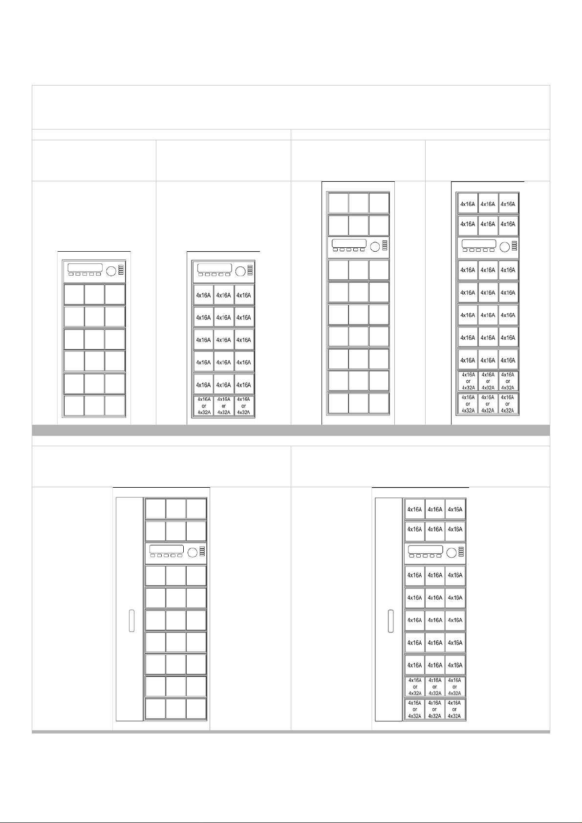
Rear Access Rack max capacity (160cm high)
Rear Access Rack max capacity (200cm high)
7541A1714: 72 x 16A
7541A1716: 72 x 16A or,
7541A1717: 108 x 16A
7541A1719: 108 x 16A or,
Swing Frame Rack max capacity (200cm high, front access)
7542A1720: 108 x 16A
7542A1722: 108 x 16A or 84 x16A and 24 x 32A
Matrix MkII Racks – standard range
7541A1715: 108 x 16A
7541A1715: 54 x 32A
60 x16A and12 x 32A
7541A1718: 162 x 16A
7541A1724: 81 x 32A
84 x16A and 24 x 32A
7542A1721: 162 x 16A
7542A1725: 81 x 32A
Page 3

Table of Contents
Introduction ........................................................... 1
How to use this guide .......................................................... 1
Warnings and Notice Conventions...................................... 1
Scope of this Guide ............................................................. 1
Module vs. Rack compatibility chart.................................... 2
Contacting ETC® ................................................................ 4
Section 1 Preparing for Installation ....................................... 5
Unpack and Inspect ........................................................... 5
Main Circuit Breaker Protection .......................................... 5
Obtain ETC Approval to Energize the System .................... 5
Local Requirements ............................................................ 6
Dimmer Room Requirements ............................................. 7
Accessibility ......................................................................... 8
Section 2 Positioning of Racks ............................................. 9
Description .......................................................................... 9
Positioning Racks................................................................ 9
Installing Cable Infrastructure ........................................... 10
Protecting Racks During Installation ................................. 10
Section 3 Installing Main Supply Cables ............................. 11
Cable Access .................................................................... 11
Fuses ................................................................................ 12
Section 4 Installing Load Cables ....................................... 13
Terminations ..................................................................... 13
Routing cables .................................................................. 13
Section 5 Installing Data Cables ........................................ 14
Ethernet ............................................................................. 14
Discrete DMX .................................................................... 14
Section 6 Finishing Installation .......................................... 15
Visual Inspection ............................................................... 15
Cleaning ............................................................................ 15
Contents
i
Page 4

Section 7 Check Power Installation .................................... 16
Checking Main Power Wiring ............................................ 16
Checking Load Wiring ....................................................... 16
Optional – Checking Line Voltages .................................. 17
Section 8 Installing the Processor and Modules ................. 17
Installing the Processor ..................................................... 17
Identifying Modules ........................................................... 17
Installing the Modules ...................................................... 18
Section 9 Preventative Maintenance .................................. 19
Fuses ................................................................................ 19
Terminations ..................................................................... 19
Ventilation ......................................................................... 19
General ............................................................................. 19
Appendix A Troubleshooting .................................................. 20
Power Loss ....................................................................... 20
RCD Tripping .................................................................... 20
To check module power and data ..................................... 21
Fan not working................................................................. 22
Data loss ........................................................................... 22
Appendix B Matrix MK II Rack Specifications ........................ 23
General ............................................................................. 23
Environmental Specification .............................................. 23
Mechanical Specification .................................................. 23
Electrical Sp ec ification ...................................................... 23
Part number for main products ......................................... 24
Part number for factory configured option kits .................. 25
Part number for spare parts .............................................. 25
Appendix C Certificates of Conformity ................................... 26
Matrix Mk.II Rack Installation Manual
Page 5
of an action.
Introduction
Welcome to the installation manual for Matrix® Mk.II dimmer racks. This manual contains the
procedures for safe and efficient installation of Matrix Mk.II rear access racks and swing frame racks
and includes information on electrical wiring installation and the complete dimming system checking. It
does not include programming and commissioning as these subjects are described in the relevant
ETC operational manuals.
How To Use This Guide
Use this guide during system installation. It contains complete installation instructions up to the point
of programming and commissioning. The procedures for programming and using the system are
described in the relevant ETC Operational Manuals.
When viewing this document in electronic form (PDF file) with Adobe Acrobat Reader, blue italicized
text followed by a page number such as Positioning of Racks, page 8, is a link within the document. If
you click on the link, the screen will display that section or topic.
Warnings and Notice Conventions
These symbols are used in Matrix Mk.II documentation to alert you to danger or important information:
Note:
CAUTION:
WARNING:
WARNING:
Notes are helpful hints and information that is
supplemental to the main text.
A Caution statement indicates situations where
there may be undefined or unwanted
consequences of an action, potential for data loss
or an equipment problem.
A Warning statement indicates situations where
damage may occur, people may be harmed, or
there are serious or dangerous consequences
RISK OF ELECTRIC SHOCK! This warning
statement indicates situations where there is a
risk of electric shock
Scope Of This Guide
This guide explains the installation procedure for the following Matrix Mk.II racks:
Rear access racks
o 1.6m 72ch 18 modules 4x16A [7541A1714]
o 1.6m 108ch 18 modules 6x16A [7541A1715]
o 1.6m 72ch 15 modules 4x16A, 3 modules 4x32A [7541A1716]
o 1.6m 54ch 18 modules 3x32A [7541A1723]
o 2.0m 108ch 27 modules 4x16A [7541A1717]
o 2.0m 162ch 27 modules 6x16A [7541A1718]
o 2.0m 108ch 21 modules 4x16A, 6 modules 4x32A [7541A1719]
o 2.0m 81ch 27 modules 3x32A [7541A1724]
Swing frame racks (front access)
o 2.0m 108ch 27 modules 4x16A [7542A1720]
o 2.0m 162ch 27 modules 6x16A [7542A1721]
o 2.0m 108ch 21 modules 4x16A, 6 modules 4x32A [7542A1722]
o 2.0m 81ch 27 modules 3x32A [7542A1725]
Introduction
1
Page 6

Module compatibility chart
SCR module 6x3kW
sensing
Rack version
Rack height
Channels (max) 72 108 72 54 108 162 108 81 108 162 108 81
7542A-- Ref. no: 7542A-- 1714 1715 1716 1723 1717 1718 1719 1724 1720 1721 1722 1725
1.6m 2.0m 2.0m
Rear access Swing frame
1001 SCR module 6x3kW ND
1003
1004*
1006
1007*
1011
1012
1014
1015
1005
SCR module 6x3kW,
RCD/Module current
sensing
Fluorescent,
RCD/modulecurrent
SCR module 4x3kW,
RCD/ch, current sensing
SCR module 4x3kW
Fluorescent, RCD/ch,
current sensing
SCR module 3x5kW,
RCD/modulecurrent
sensing
SCR module 3x5kW,
RCD/ch, current sensing
SCR module 3x5kW,
current sensing
SCR module 2x5kW,
current sensing
SINE 4x3kW, ND, current
sensing
1008
1010
1009
* These modules require a special cable kit. Contact your ETC supplier for details.
SINE 4x3kW, RCD/ch,
current sensing
SINE 2x5kW, ND, current
sensing
SINE 2x5kW, RCD/ch,
current sensing
Matrix Mk.II Rack Installation Manual
Page 7

Rack version
Rear access
Swing frame
Rack height
Channels (max) 72 108 72 54 108 162 108 81 108 162 108 81
7541A-- Ref. no: 7542A-- 1714 1715 1716 1723 1717 1718 1719 1724 1720 1721 1722 1725
7541A1200
7541A1201
7541A1202
7541A1312 Dual processor
7541A1401
7541A1402
7541A1403
7541A1405
7541A1406
iSW Relay 4x16A,
RCBO/ch current
sensing
iSW Relay 6x16A,
MCB/ch, current
sensing
iSW Relay 6x16A,
RCD, MCB/ch,
current sensing
iCON Constant
power 6x16A,
MCB/ch
iCON Constant
power 6x16A,
RCD, MCB/ch
iCON Constant
power 4x16A,
RCBO/ch
iCON Constant
power 1x63A,
RCD, MCB
iCON Constant
power 3x32A,
RCBO/ch
1.6m
2.0m
2.0m
7542A1501 Airflow module
Introduction
3
Page 8

Contacting ETC®
Please email comments about this manual to: TechComm@etcconnect.com
For questions about Matrix Mk.II rack system delivery, contact ETC Systems Group. For general
information/technical que stio n s about Matrix Mk.II rack systems, contact ETC Technical Services.
Americas
ETC International
Technical Services Department
3031 Pleasant View Road
Middleton, WI 53562
+1 608 831 4116
service@etcconnect.com
Europe
ETC Europe Ltd.
Technical Services Department
26-28 Victoria Industrial Estate
Victoria Road
London W3 6UU England
+44 (0)20 8896 1000
service@etceurope.com
Asia
ETC Asia Ltd.
Technical Services Department
Room 1801, 18/F
Tower I, Enterprise Square
9 Sheung Yuet Road Kowloon Bay,
Kowloon, Hong Kong
+852 2799 1220
service@etcasia.com
Matrix Mk.II Rack Installation Manual
Page 9
1
If it is suspected that a rack has been damaged in transit check
correctly.
Do not attempt to energize the system without proper approval.
injuries.
Section 1
Preparing for Installation
Unpack and Inspect
Before starting the installation, check the shipment to confirm it arrived complete and undamaged. A
Matrix II rack is shipped empty of modules in a transit box suitable for movement by a pallet truck. The
modules and processor are separately packed in individual single-use tran sit boxes. Each rack has an
identification label mounted inside the rear door with a serial number and CE mark. Also enclosed in
the rack is a document holder for this installation manual and the rack’s schematic diagram.
carefully that the chassis framework is not distorted as eve n a minor
amount of structural change in the framework can prevent the
CAUTION:
Step 1: Check all shipping containers for physical damage.
Step 2: If you find damage, document it with photographs to help with a claim
Step 3: Unpack your order and check the contents against the packing list to be
Step 4: If you discover a problem, call ETC Systems Group (details on page 4).
modules from being inserted or removed. This is particularly
important in the case of swing frame racks, as any distrortion of the
chasis frame will prevent the swing frame opening and closing
against your shipper.
sure your order is complete.
Main Circuit Breaker Protection
Before beginning installation of your Matrix Mk.II dimmer rack(s), make sure a main circui t break er
cabinet or other readily accessible input power disconnect device is installed. See Appendix B: Matrix
MkII Rack Specifications, for individual rack power requirements.
WARNING:
Dimmer racks installed without an accessible power disconnect
device cannot be serviced or operated safely.
Obtain ETC Approval to Energize the System
Following installation, ETC approval is required to apply power to the dimming system. Pre-approval
may be granted for some installations during the purchase process, or following a wiring inspection by
an authorised ETC representative after the system is installed. Wiring errors in unauthorised
installations may endanger operators or cause system damage and failure.
WARNING:
CAUTION:
Energizing the system without ETC approval may result in serious
Energizing your system without ETC approval may result in equipment
damage that may not be covered under your warranty!
Preparation for Installation
5
Page 10

Local Requirements
European Requirements
Matrix II has been designed to European standards for electrical switchgear
EN60439. It is CE marked. See Appendix C: Matrix II Declaration of Conformity.
Ensure that all European electrical health and safety, and working directives are
met when installing Matrix II.
Power Supply Requirements
Standard Matrix II racks are designed for operation with a single 3-phase star
380V – 415V RSTNE supply. Special order delta wired racks and multiple feed
racks are outside the scope of this manual. Contact your local ETC distributor for
more information. Please see Appendix B: Matrix Mk.II+ Rack Specifications, for
electrical specification detail s.
Supply Cable Requirements
Main power supply cables must be suitable for the type of dimming installation, the
anticipated load (with diversity factor) and to meet local regulations. Single
conductor or stranded conductors in either copper or aluminium may be used with
suitable terminations. Phase bars include 10mm (M10) bolts for termination of
mains power.
Load Cable Requirements
Cables connecting the dimmer outputs to load sockets must be suitable for the
type of dimming installation, for the anticipated maximum load and to meet local
regulations. Matrix II is designed for 3-wire per circuit load wiring (phase, neutral
and earth). Installati ons with s har ed neutr al conn ect ion s can not be used w ith
modules incorporating RCD protection.
Data Cable Requirements
Ethernet data cables should be at least CAT5 rated, and CAT6 is recommended
for dimming installations due to its increased bandwidth and future upgrade
potential.
Matrix Mk.II Rack Installation Manual
Page 11

1
It is important to ensure that the rack is vertical, as even a minor
correctly.
Dimmer Room Requirements
Location
o A clean (not dusty) temperature-controlled environ ment
o Restricted public access to prevent any unauthorised tampering with the dimmer
settings
o Soundproofing or
Please see Appendix B: Matrix Mk.II+ Rack Specifications, for environmental
details.
Ventilation
o The dimmer room requires adequate ventilation to accommodate the heat
generated by the dimming system and to maintain a working temperature of less
than 35degC. For planning purposes allow for a thermal output of 3% of the
available power. Air conditioning is recommended. Ventilation input is through the
rear door grille and a grille at the bottom of the front of the rack. The hot air
exhaust is through the front of each module.
Please see Appendix B: Matrix Mk.II+ Rack Specifications, for environmental
details.
Access to dimmer room
o Before attempting to move the rack(s) into the final position, check access routes
to the dimmer room for space to manoeuvre through doorways and around
corridor corners. Dimmer rack dimensions are provided in Appendix B.
performance area separation to muffle ventilation fan noise.
Electrical
o A main circuit breaker cabinet or other readily accessible input power disconnect
o It is recommended that during the installation process all disconnected isolation
Floor Surface
o Matrix II racks require a flat, stable and solid floor surface which can
CAUTION:
device is required. Main breakers which are not located in the same room must
have a physical means to be locked off and disabled.
devices associated with the racks are clearly marked so they will not be switched
on in error.
2
accommodate a load of 1000 kg/m
beneath, a plinth with a suitable load carrying capacity is required in advance of
the introduction of the racks to the dimmer room. This can be achieved by using a
computer floor or optional Matrix II rack plinths.
amount of structural distortion in the framework can prevent the
modules from being inserted or removed esily. This is particularly
important in the case of swing frame racks, as any distortion of the
chassis frame will prevent the swing frame opening and clo si ng
[230lb/ft2]. If cable entry is required from
Preparation for Installation
7
Page 12

Accessibility
Allowing space around the rack (Rear access racks)
Allowing space around the rack (Swing frame racks)
o Rear access racks require adequate space in front to remove and replace
modules (minimum 80cm, 150cm recommended) and rear access to allow the
rear door for ventilation purposes and so that the door can be opened fully for
installation and maintenance access (minimum 100cm, 180cm recommended).
o Racks may be positioned with their side to a wall surface, and may be located
side to side as required.
o Where top access is planned for cables, ensure space above the rack is
adequate to allow for the bend radius of the supply cable, or access for main
power supply cable or bus bar trunking and load cable trunking. Allow adequate
space to allow for future cable checking and maintenance access to trunking lids.
o Swing frame racks require adequate space in front to remove and replace
modules and sufficient space for the door to be hinged fully open for access to
wiring terminations inside the rack. A distance of 1.8m is recommended between
the front of the rack and the wall.
o Racks may be positioned with their side and rear to a wall surface, and may be
located side to side as required.
o Where top access is planned for cables, ensure space above the rack is
adequate to allow for the bend radius of the supply cable, or access for main
power supply cable or bus bar trunking and load cable trunking. Allow adequate
space to allow for future cable checking and maintenance access to trunking lids.
Please see section 2 for mechanical dimensions.
Cable Routing
o Load cables and supply cables can be routed through the top or base of the
racks. Protect all edges to avoid cable insulation damage.
Matrix Mk.II Rack Installation Manual
Page 13

2
Section 2
Positioning of Racks
Description (Rear Access racks)
Rear access racks are available in 160cm or 200cm
high versions and are available in 4 standard module
configurations for each version. Both height versions
are 60cm wide and 80cm deep. Each rack is supplied
with two side covers. The supplied intermediate side
panels may be discarded between racks.
Adequate space is required to the front for removing
and replacing modules and the processor, and space
at the rear should be available for fully opening the
rear door and allowing adequate access for wiring.
The rear door panel is also the main air intake for
ventilating the dimmers and must not be obscured.
dimension 18 modules 27 modules
a 160cm 200cm
b 80cm 80cm
c 60cm 60cm
d 80cm min. 80cm min.
e 80cm min. 80cm min.
Description (Swing Frame racks)
Swing frame racks are 200cm high, 80cm wide and 83cm deep
(including the rear stand-off ventilation panel) and are available
in 4 standard configurations. Racks are not supplied with side
covers but may be ordered separately to cover exposed sides.
Adequate space is required to the front for removing and
replacing modules and the processor, and for fully openi ng the
front swing door sufficiently to allow adequate access for wiring.
The rear panel is spaced approx. 10mm from the rear of the
rack to provide an air intake for
ventilating the dimmers. This
space must not be obscured.
dimension 27 modules
a 200cm
b 83cm
c 80cm
d 100cm min.
Installation of Racks
9
Page 14

Positioning Racks
It is important to ensure that the rack is located on a horizontal,
and closing correctly.
The racks are heavy, so it is advisable to prepare carefully before moving the racks into their final
position to avoid having to reposition racks if something is not ready, or the racks are not positioned in
the correct order. Check the delivery documents and installation drawings in advance to ensure that
the racks are positioned in the correct order because there are three versions of wiring and it is
difficult to differentiate between the versions visually without detailed internal inspection. Racks placed
in the wrong order can be inconvenient to change subsequently and if incorrectly placed will affect the
logical arrangement of module positions and channel numbering in the dimmer room.
Because the permitted module combination for similar size racks is not immediately obvious, it is
recommended that each rack version is initially identified by part number (see pages 1-3). If a mixture
of different modules is to be used, such as 4-c han nel and 6-channel modules or a combination of
3kW/16A and 5kW/32A modules or fluorescent or special modules, the different versions of racks will
have to be arranged to match the required module and channel numbering preferences.
Make sure the floor is clean, horizontal, flat and sound, and if several racks are to be located together,
mark out the floor in advance.
stable floor surface so that the rack is exactly vertical, as even a
minor amount of structural distortion in the framework can prevent
CAUTION:
Before attempting to move or position a rack, it is recommended that the side and top panels and rear
door are removed as this reduces the weight of the rack considerably (each rear access rack’s side
panel weighs approximately 35kg). Repla ce the panels as needed, after positioning.
For installations where bottom-access cable access is planned, prepare a suitable computer floor or
position optional rack plinths (100mm or 200mm high). If plinths are used, bolt these to the dimmer
room floor ensuring that they are in line and horizontal. Remove intermediate blanking plates to allow
for free cable access. Extreme care is required when lifting Matrix II racks into position. Bolt the racks
to their plinths when they are in place.
For top-access cable installations, and If racks are to be placed in a group side by side, there is no
requirement to bolt them together as the weight and cable infrastructure will ensure they won’t move.
If rigid fixing is preferred, the lifting eye bolts at the top of each rack can be used with custom-made
straps to lock adjacent racks together.
the modules from being inserted or removed easily. This is
particularly important in the case of swing frame racks, as any
distortion of the chassis frame will prevent the swing frame opening
Installing cable infr a s tructure
With the racks situated in the correct location, the next step is to position and fix the supply and load
access. The style and method of this depends local wiring regulations, licensing authority preferences
and electrical contracting techniques. The main supply to each rack may be a single tri-rated 400A 3phase armoured cable, 3-phase bus bar trunking with tap-off points for each rack, or individual
conductors in trunking or within the computer floor or optional rack plinths. Similarly, load cables may
be routed to each rack by individual cable ways, or trunking, or shared trunking with multiple tap-off
points. The installation of the external cable routing is not within the scope of this handbook.
Cable entry points are available through the top of the rack (the removable top panel may be cut as
required), or through the base of the rack where two panels are removable to provide access to space
beneath the rack. It is recommended that where possible the cable entry covers are removed from the
rack to reduce the risk of debris affecting the multi-pin connectors and terminations in the rack.
Protecting the racks during install at io n work
The dimmer modules and processor unit of a Matrix II rack should not be unpacked or installed until
all building preparation, rack installation and wiring work is complete. It is strongly recommended that
the internal sockets, terminals and associated PCBs are protected against damage from building
debris, dust ingress, metal shavings during the period until the dimmer room is finally cleaned and
tidy.
Matrix Mk.II Rack Installation Manual
Page 15

3
Ensure that it remains impossible to apply power to the main supply
DURING THIS INSTALLATION PROCESS.
Section 3
Installing Main Supply Cable s
cable while installation of the main supply rack connections are being
WARNING:
Matrix II racks may be ordered with a 400A internal bus bar/fuse assembly which is located on the
right side of the rear of the rack (rear access racks) or on the left side from the front (swing frame
racks). The bus bar may be used for either top or bottom cable access points and is factory fitted for
bottom cable access as shown here.
Cable Access
To install main supply cables from the top or bottom of the rack
Note : Cable termination to Matrix MkII racks is made using M10 bolts. It is the installers responsibility
to provide and terminate a suitable lug for the size and type of cable in use in an installation.
made. Ideally, connect the main supply cables to the dimmer racks
before making connections to the supply switchgear. IT MUST NOT BE
POSSIBLE TO ACCIDENTALLY APPLY POWER TO THE RACK
• Determine desired cable entry point (top or bottom).
• Remove the fuse cover panel (rear access rack) or the bus bar
termination cover (swing frame rack).
• Dress the feeder cables neatly into the rack and support them using
the perforated strap bars in the side of the rack to reduce
mechanical stress on the bus bar terminations.
• Once the cables are run to the desired termination point, strip the
cables and terminate the lugs to them, following the instructions
from the lug manufacturer.
• Secure the lug to the phase bar using the provided M10 bolt and
spring washer (see diagram).
• Tighten the bolt to 55 N-m (40 lb-f) using a torque wrench. (The
55Nm torque is the suggested tightness for standard engineering
steel bolts.)
• Repeat for all phase and neutral connections.
• Locate the three snap-
on ferrite toroids that are
provided with the
installation kit. Snap
each ferrite to the mains
input protective earth
(PE) cable. Stack the
ferrites together on the
cable and secure each
with a cable tie (not
provided). Optionally
add a cable tie on the
ground cable at each
end of the ferrite toroids
to avoid movement on
the cable.
CAUTION:
Installing Main Supply Cables
11
Ensure that supply cables are adequately
supported to avoid any strain to the bus bar
connections.
Page 16

Fuses
Any custom module with 4x5kW capacit y is restricted to the module maximum
will exceed the module’s 80A fuse rating.
The fuse protection employed in the rack provides a single 63A Siemens type D02 for each module
position, and three 25A Siemens type D02 fuses for the processor. The module fuses limit the
maximum current available to each module to 63A. The three processor fuses are located at the top
row of the fuse panel on both the 1.6m and 2m high racks. In addition, each module incorporates a
15A 32mm A/S fuse per dimmer or switch power section.
Simplified schematic diagram of the circuit protection route from main supply breaker
through the Matrix II bus bars to a module RCBO and channel fuse to the output load.
capacity rating of 80A. This means that although th e modu le has four cir cuit s,
Note:
each with a maximum rating of 5kW (21.7A at 230V), if a full y -loaded 4channel 5kW module is used to its full capacity (4 channels x 21.7A =86A) it
Matrix Mk.II Rack Installation Manual
Page 17

5
Load circuit neutral must be
or RCBO nuisance tripping.”
Section 4
Installing Load Cables
Terminations
Terminals for the load wiring are located to the left of the rack at the rear and are accessible when the
rear door is opened. The terminals for 3kW circuits are arranged in groups of three (L, N, E)
corresponding to the number of channels in each row (3 modules) of the cabinet. Terminals for 5kW
and 12kW circuits are located in pairs with the earth terminals located separately but adjacent to the L
and N terminals. The load terminals are wired in groups for each row of modules. Load wires may be
stripped to bare ends or (better) stripped and fitted with crimp ferrules before insertion into the
terminal blocks.
Load terminal sizes
Up to 3kW circuits:6mm
5kW circuits: 10mm
12kW circuits: 16mm
2
[AWG 12]
2
[AWG 8]
2
[AWG 4]
Routing load cables
When drawing load cables into the
rack, ensure that no insulation is
damaged by edges of trunking or
access apertures. If the wiring has
been pre-designated and includes
temporary labelling to identify circ uit
numbers, be careful not to dislodge
labels during the wiring process.
Dress and terminate the wires neatly
and avoid leaving extra wire or
discarded sleeving in the rack. The
horizontal bars behind each tray are
perforated to accommodate cable ties
for this purpose. Load wiring should
not place any strain on the terminal.
In the diagram right, the load cables
(a) enter from the bottom of the rack
and are neatly clipped to the
horizontal tie bars on the rear of each
shelf (b). They are dressed in bunches
according to the location of the load
terminals (c). Care should be taken
when routing the load cables so they
do not obstruct the load terminal
screws. Data cables (d) are similarly
routed and clipped to the trays.
Load wiring should not cross between
racks; they should only enter the rack
in which they are terminated. Live and
neutral load wiring must follow the
same path for each circuit and should
remain in pairs to the appropriate
terminals.
terminated in the same
CAUTION
module position as its paired
live conductor to avoid RCD
Installing Data Cables
13
Page 18

Section 5
Installing Data Cables
All Matrix II dimmer racks accept data in Ethernet and discrete DMX formats. All control connections
are made at the rear of the processor module, on the data PCB that can be identified by the attached
ribbon cable. There is one data PCB per rack. Use provided lance and forms as a tie off for DMX and
Ethernet cables in the swing frame racks.
Data PCB at the rear of the Matrix II Processor tray.
a) DMX 1 & DimStat discrete DMX connections
b) DMX 2
c) Ethernet 1 RJ45
d) Ethernet 2 RJ45
Ethernet
Two standard RJ45 Ethernet sockets are provided on the data PCB, one for
the reporting connection (Dimstat) and one for the control data connection
(Merger). These sockets accept standard 10- or 100-base-T network
connections and receive dimmer intensity levels and transmit dimmer status
information using the DimSt at proto col.
Discrete DMX
Separate data terminals are included for DMX for those installations which are
not using an Ethernet data network. Two sets of terminals are included (see
diagram opposite). The terminals are PCB plug and socket type and may be
removed for wiring. DMX-1 includes the RS422 connections to DimSTAT and
DMX-2 is for DMX only.
DMX wiring should follow the standards and topology as defined by the USITT
standard. Wiring a Matrix II connector is as shown to the right. Unplug the
terminal section for wiring.
Matrix Mk.II Rack Installation Manual
Page 19

6
Section 6
Finishing Installation
Visual inspection
After the supply, load and data terminations are completed, the rack should be checked as follows:
o Check all terminals and fuses have been tightened, especially the earth bonding
points
o Tidy all internal cables and add cable ties where needed
o Remove excess or unwanted wiring
o Fit the bus bar cover panel
o Secure all removable panels
o Remove all temporary protective covers
Cleaning
Before installing any electronic s modul es, en sure t hat the rack is free from dust, any building debris.
ETC recommends that the inside of the rack is vacuum cleaned to remove any debris from the wiring
installation process. Special attention should be paid to the multi-pin sockets used to connect to the
processor and modules.
When the rack is clean and ready for use, close and lock the rear door.
Finishing Installation
15
Page 20

Section 7
Check Power Installation
Checking main power wiring
WARNING:
Check resistance between phases, neutral and earth busses.
o Phase to phase; resistance should be 10M Ω or higher
o Phases to earth; resistance should be 10M Ω or higher
o Neutral to earth; resistance should be 0Ω
o Phase to neutral; resistance should be 10M Ω or higher
Power must be turned OFF when you perform this procedure.
Checking load wir in g
Check resistance between the load terminals and the neutral bus:
o Above 1 MΩ - Normal when no load is connected
o Between 1 - 1000Ω - Normal w hen loads are conne cted
o Below 1Ω - Indicates a dead short in the load wiring
WARNING:
A dead short can cause dimmer module damage.
Matrix Mk.II Rack Installation Manual
Page 21

8
Section 8
Installing the Processor and Modules
Before unpacking and installing the electron ic
CAUTION:
Identify the modules used in the system and separate the processor from the Matrix II modules.
Locate the operator manuals from the processor and modules as these will be required during the
installation process. If different styles of module are planned for racks within the system, refer to the
installation documentation to identify which modules are to be used in each rack.
Installing the Pr oc e s s or
Step 1: Locate the processor module and check that the MCBs on the front panel
are switched off (levers in the down position).
Step 2: Slide the processor into the appropriate wide slot in the front of rack. This
is the top position in a 1.6m rack, and the third row from the top in a 2m
high rack. Do not use excess force if resistance is felt from the connectors.
Remove the unit and check the sockets line up correctly and no pins are
bent. The processor should slide in and connect with its multi-pin
connector smoothly. When in place, the front panel of the processor will be
flush with the surround ing met alw or k.
Step 3: Switch all MCBs on (levers to the up position).
Step 4: Observe the processor powering up which, after a short time, will be
displaying the default screen (details are given in the Matrix II Processor
Operator manual) and all three phase on indicators illuminated.
Step 3: Use the screws supplied with the processor to fix the unit in place.
modules into the Matrix rack, ensure that all
terminals have been correctly tightened, the rack is
clean and any protective plastic has been removed.
Identifying modules
There is a wide range of modules available with the Matrix II system as listed in pages 2 and 3, and it
is important to fit them in the correct slot if a selection of modules has been specified with the system.
Each type of module sharing the same capacity and quantity of channels will fit the same appropriate
slot in the rack, but modules of different capacity and quantity of channels are prevented by keyways
in the multipin sockets.
In mixed installations where, for example, sinewave dimmers are specified for particular circuits and
SCR dimmers for others, it is important to ensure they are in the correct slot for operat iona l reaso ns.
Before starting to install the dimmer modules, check system schematics and design documentation for
a schedule of which module fits in each slot.
Installing Processor and Modules
17
Page 22

Installing the mod ule s
that the connector has a damaged pin.
WARNING:
CAUTION:
Step 1: Locate the correct module for each slot and check that the MCBs / RCBOs
Step 2: Slide each module into its appropriate slot in the front of rack, one at a
Step 3: Observe the module powering up which, after a short time, will show a
Step 4: Use the screw supplied with the module to fix it in place.
Do not force any module into a connector if
resistance is felt. This could mean that the
wrong module is being inserted into the slot, or
SWING FRAME RACK
Before installing any modules, close the sw ing
frame and lock it.
on the front panel are switched off. Note that any blank spaces in the rack
should be fitted with ‘airflow’ modules.
time. This can be done safely with power applied to the rack. Do not use
excess force if resistance is felt from the connectors. This may be due to
damaged pins, or a stand-off pillar which prevent s a 3k W module being
inserted into a 5kW load position. Remove the module and check the
sockets line up correctly and no pins are bent (see diagram below). A
module should slide in and connect with its multi-pin connector smoothly.
When in place, the front panel of each module will be flush with the
surrounding metalwork.
single blue power on LED if all channels are at zero (details are given in
the Matrix II Module Operator manual).
Matrix Mk.II Rack Installation Manual
Diagram of the module connector options in
the Matrix Mk II rack, when viewed from the
front of the rack. Note the position of the
interlock standoffs for the 16A and 32A rated
modules arrowed. For pin-out details, see
Appendix A.
Page 23

9
Section 9
Preventative Maintenance
ETC Matrix II dimming systems are designed for long and reliable service, but will benefit from annual
checks of parts of the system. This section outlines the sort of checks which should be part of any
regular maintenance regime.
Fuses
o With power switched off, remove each fuse and inspect for corrosion or any signs
of arcing
o Replace any fuse carriers which appear cracked or damaged in any way
o Replace the fuses and check they are tight in the fuse carriers and are not
inserted at an angle to the bus bars
o Replace all fuses every 5 years to prevent nuisance failure through aging
Terminations
o With the main supply isolated from the rack, check the bus bar fixings are tight.
o Check the tightness of all load terminations.
o Check all data cables and make sure they are correctly located in their sockets.
Ventilation
o On each module, depress the test button (on the front panel) for 5 seconds to test
the operation of the fan.
o Replace the fan if it does not run, or if it is noisy
General
o Clean all modules, fans and the rack.
Preventative Maintenance
19
Page 24

Appendix A
Troubleshooting
Power loss
Total power failure
If all power to the rack fails (if it is not already obvious, the processor’s three phase
indicators will be off when there is a total power loss) initially check if the main
supply breaker has tripped. If not, check if there is any other equipment supplied
from the same source and whether or not that is working correctly. If other
equipment is working correctly, trace the supply route back to where the supply
splits to the rack and investigate the cause for the loss at that point.
Single or dual phase failure
Due to Matrix II’s distributed fusing design within the rack, a loss of one or two
phases could be caused by several different faults.
o If the processor indicates a phase has been lost, and yet all modules in the rack
are displaying power on, switch off all power to the rack and check the processor
supply fuses at the rear (top row of the fuse panel).
o If the processor indicates a phase has been lost, and the cor respo ndi ng colu mn
of modules appear to have switched off (indicator LEDs are off), check the mains
supply for a tripped phase breaker or fuse.
Single module power failure
If all power is lost to one module only, initially check the module supply fuse (63A)
on the Matrix fuse panel (only check with the main power off) and replace it if
necessary.
Single channel power failure
RCD tripping
RCD tripping on installation
RCD tripping after previously working correctly
If there is no output from one channel only (this will be reported by DimSTAT, on
the Processor and the module), it can indicate that the MCB or RCBO has tripped,
or there is an electronic failure within the module.
If an RCD trips during initial testing of the rack, it is almost certain there is a load
wiring problem. It is vital that both the live and neutral conductors of each channel
are routed together and connected to the corresponding phase and neutral outputs
from the same module. If the cause is not obvious, check first that there is no load
plugged into the circuit (the load may be at fault). With the load wiring isolated,
check there are no loose strands between terminals that could allow a leakage
current between the phase, neutral or earth connection.
Check that the load plugged into the circuit is not at fault by performing a PAT test
on the luminaire. If the load is not at fault, recheck the circuit to make sure there
isn’t another load connected in parallel which could be experiencing a leakage
current between L and E or N and E.
Matrix Mk.II Rack Installation Manual
Page 25

A
The Matrix rack has inherent safety from electrical shock if a module
technician,
Multipin socket for 6 x 3kW module
Multipin socket showing the position of the standoff pillar (arrowed) and pin numbering.
Mod. A
Pin
Connection
1
Ch 1 - L
2
Ch 2 - L
3
Ch 3 - L
4
Ch 4 - L
5
Ch 1 - N
6
Ch 2 - N
7
Ch 3 - N
8
Ch 4 – N
Mod. B
1
Ch 5 - L
2
Ch 6 - L
5
Ch 5 - N
6
Ch 6 -N
Multipin socket for 3 x 5kW module
Mod. A
Multipin socket showing the position of the standoff pillar (arrowed) and pin numbering.
Pin
Connection
1
Ch 1 - L
2
Ch 2 - L
3
Ch 3 - L
5
Ch 1 - N
6
Ch 2 - N
7
Ch 3 - N
Mod. B
1
Ch 1 - L
2
Ch 2 - L
3
Ch 3 - L
5
Ch 1 - N
6
Ch 2 - N
7
Ch 3 - N
Multipin socket for 4 x 3kW module
Multipin socket showing the position of the standoff pillar (arrowed) and pin numbering.
Mod. A
Pin
Connection
1
Ch 1 - L
2
Ch 2 - L
3
Ch 3 - L
4
Ch 4 - L
5
Ch 1 - N
6
Ch 2 - N
7
Ch 3 - N
8
Ch 4 - N
To check module power and data
WARNING:
It is possible to access the module sock from the front of the rack to aid fault finding. There are three
standard multipin socket configur ati ons :
o 4-channel 16A sockets (for 4 channel, max 3k W modules)
o 6-channel 16A sockets (for 6 channel, max 3k W modules)
o 4-channel 32A sockets (for 4 channel, max 5kW modules (custom), 12kW etc)
The 3kW (16A) and 5kW (32A) versions of the multipin sockets have standoff pillars on opposite
sides to prevent incorrect modules being inserted.
is removed with power on. However, the following checks on the
rack socket connections should only be attempted by a qualified
Note that Mod A and Mod B are paralleled.
Troubleshooting
21
Page 26

Multipin socket for 4 x 5kW module (Custom 32A and standard 63A/12kW modules)
Multipin socket showing the position of the standoff pillar (arrowed) and pin numbering.
Note that Mod A and Mod B are paralleled.
Mod. A
Pin
Connection
1
Ch 1 - L
2
Ch 2 - L
3
Ch 3 - L
4
Ch 4 - L
5
Ch 1 - N
6
Ch 2 - N
7
Ch 3 - N
8
Ch 4 - N
Mod. B
1
Ch 1 - L
2
Ch 2 - L
3
Ch 3 - L
4
Ch 4 - L
5
Ch 1 - N
6
Ch 2 - N
7
Ch 3 - N
8
Ch 4 - N
Fan not working
With Matrix II, the ventilation fans are located in each module. They are activated only when the
module reaches a pre-set internal temperature of 35degC, and they increase in speed in proportion to
the amount of heat present. To check the operation of the fan, depress the test button on the module
for about 5 seconds, after which time the fan will switch on. If it does not switch on, the fan may need
replacing.
Data loss
Data loss at the processor
No data present at the processor is displayed on the processor panel by an X
against the DMX legend. If this is the case, test the output from the control system
through any intermediary buffers, routers or switches.
If the data is correct, disconnect power from the rack and at the rear of the
processor swap the connections between inputs 1 and 2 (Ethernet 1 and 2 or DMX
1 and 2 depending on the data used) to see if the problem can be traced to the
different internal processing routes. If the data signal appears on the alternative
channel, the problem may be in the processor. If the second input does not
respond to the data signal, there is a problem with the data wiring to the rack.
Data loss at a single module
In the first instance, simply exchange the module with no data with an adjacent
module of the same type to check if the replacement responds to data. If it does,
the module is at fault. Check the module’s data cable (flat ribbon cable) to make
sure it is not damaged and is firmly located in its socket.
Data loss at a row or column of modules
If data is present at the processor but one row of modules has lost data, the
problem may be with the data connection PCB which is accessible from the rear of
the rack. Data is connected vertically through the rack via a ribbon cab le, so in the
first instance check that the cable connection is corr ect ly made and the ribbon
cable is locked in place.
Matrix Mk.II Rack Installation Manual
Page 27

B
Appendix B
Matrix Mk.II Rack Specifications
General
Racks are available in nine configurations:
1.6m high Rear Access (RA) racks [160cm x 60cm x 80cm 170kg (excluding modules)]
o 72ch 18 modules 4x16A [7541A1714]
o 108ch 18 modules 6x16A [7541A1715]
o 72ch 15 modules 4x16A, 3 modules 4x32A* [7541A1716]
2.0m high Rear Access (RA) racks [200cm x 60cm x 80cm 215kg (excluding modules)]
o 108ch 27 modules 4x16A [7541A1717]
o 162ch 27 modules 6x16A [7541A1718]
o 162ch 21 modules 4x16A, 6 modules 4x32A* [7541A1719]
2.0m high Swing Frame (SF) racks [200cm x 80cm x 83cm 260kg (excluding modules)]
o 108ch 27 modules 4x16A [7541A1720]
o 162ch 27 modules 6x16A [7541A1721]
o 162ch 21 modules 4x16A, 6 modules 4x32A* [7541A1722]
* Modules are limited to a maximum current per module of 63A and will not provide 100% power out
for 4 x 32A simultaneous loads.
Environmental specification
Operating temperature: 0-35degC
Dimmer room HVAC systems must at all times maintain the specified ambient temperature at the
dimmer rack. Dimming systems operating within 5degC of the upper or lower temperature limits must
strictly follow installation and operation guidelines to operate reliably.
Relative humidity: 30%-90% non-condensing.
Mechanical specification
Rugged steel construction. Fine-textured scratch resistant epoxy paint. Top trunking/conduit access
through plain steel cover panel. Bottom cable access through removable panels.
Front access to processor controls and indicat ors and fitting / r emov al of dim mer modu le s.
Air intake through perforated rear door panel.
Each module fitted with ventilation fan with exhaust to front.
All modules and processor may be locked in place with supplied screw.
Electrical specification
Three phase 380-415 VAC Star system, line frequency 47-63Hz
Maximum current 400A per phase (600A option available)
Load terminals are 4mm2 [12 AWG] up to 3kW, 10mm2 up to 5kW [8 AWG] and 16mm2 [4 AWG] up to
12kW.
50,000 AIC rack rating
All racks are CE compliant.
Specifications
23
Page 28

Part numbers – main product items
Racks
7541A1714
1.6m RA Rear Access Rack, 72ch 18 modules 4x16A
7541A1715
1.6m RA Rear Access Rack, 108ch 18 modules 6x16A
7541A1716
1.6m RA Rear Access Rack, 72ch 15 modules 4x16A, 3 modules 4x32A
7541A1717
2.0m RA Rear Access Rack, 108ch 27 modules 4x16A
7541A1718
2.0m RA Rear Access Rack, 162ch 27 modules 6x16A
7541A1719
2.0m RA Rear Access Rack, 108ch 21 modules 3x16A, 6 modules 4x32A
7542A1720
2.0m SF Swing Frame Rack, 108ch 27 modules 4x16A
7542A1721
2.0m SF Swing Frame Rack, 162ch 27 modules 6x16A
7542A1722
2.0m SF Swing Frame Rack, 108ch 21 modules 3x16A, 6 modules 4x32A
7541A1723
1.6m RA Rear Access Rack, 54ch 18 modules 3x32A
7542A1724
2.0m RA Rear Access Rack, 81ch 27 modules 3x32A
7542A1725
2.0m SF Swing Frame Rack, 81ch 27 modules 3x32A
Modules
7542A1001
iSCR module 6x3kW, 6 x 13A-C MCB, 400uS, Neutral Disconnect
7542A1003
iSCR module 6x3kW, 63A/30mA RCD, 6 x 13A-C MCB, current sensing
7542A1004
iSCR module 6x3kW Fluorescent, 63A/30mA RCD, 6 x 13A-C MCB, 400uS, current sensing
7542A1006
iSCR module 4x3kW, 4 x 13A/30mA RCB per channel, 400u S , current sensing
7542A1007
iSCR Fluorescent module 4x3kW, 4 x 13A/30mA RCB per channel, 400uS, current sensing
7542A1010
iSCR module 1x12kW, 63A/30mA RCD, 63A-C MCB, 350uS, current sensing
7542A1011
iSCR module 3x5kW, 63A/30mA RCD, 3 x 25A-C MCB, 350uS, current sensing
7542A1012
iSCR module 3x5kW, 3 x 25A/30mA RCB per channel, 350uS, current sensing
7542A1013
iSCR module 3x5kW Fluorescent, 3 x 25A/30mA, 350uS, current sensing
7541A1015
iSCR module 3x5kW, 3 x 25A-C RCD per channel, current sensing
7541A1016
iSCR module 3x5kW, 3 x 25A-C MCB, current sensing
7542A1005
iSINE module 4x3kW, current sensing
7542A1008
iSINE module 4x3kW, 4 x 13A/30mA RCBO, current sensing
7542A1009
iSINE module 2x5kW, 2 x 25A/30mA RCBO, current sensing
7542A1010
iSINE module 2x5kW, 2 x 25A Neutral Disconnect, current sensing
7541A1200
iSW Relay module 4x16A, 4x16A/30mA RCBO, current sensing
7541A1201
iSW Relay module 6x16A, 6x16A MCB, current sensing
7541A1202
iSW Relay module 6x16A, 63A/30mA RCD, 6 x 3kW (16A)-C MCB, current sensing
7541A1205
iSW Relay module 3x32A, 3x32A/30mA RCBO, current sensing
7541A1206
iHMI Switch module 3x4kW, 3x32A/30mA RCBO, current sensing, cosine measurement
7541A1312
Dual full tracking processor
7541A1401
iCON Constant power module 6x16A, 6x16-C MCB
7541A1402
iCON Constant power module 6x16A, 63A/30mA RCD, 6x16A-C MCB
7541A1403
iCON Constant power module 4x16A, 4x16A/30mA RCBO
7541A1405
iCON Constant power module 1x63A, 63A/30mA RCD, 63A-C MCB
7541A1406
iCON Constant power module 3x32A, 3x32A/30mA RCBO
7541A1753
Airflow module
Plinths for RA racks
7541K2011
RA Rack Plinth 100mm
7541K2012
RA Rack Plinth 200mm
Matrix Mk.II Rack Installation Manual
Page 29

B
technicians.
Kits
7541K1001
Matrix MkII RA (Rear Access Rack) 32A/5k W module 10mm2 terminal conversion kit
7541K1007
Matrix MkII RA (Rear Access Rack) 63A/12kW module 16mm2 terminal conversion kit
7541K1002
Matrix MkII RA (Rear Access Rack) Fluorescent module conversion kit
7541K1003
Matrix MkII RA (Rear Access Rack) HMI module conversion kit
7541K1004
Matrix MkII SF (Swing Frame Rack) 32A/5k W module 10mm2 terminal conversion kit
7541K100?
Matrix MkII SF (Swing Frame Rack) 63A/12kW module 16mm2 terminal conversion kit
7541K1005
Matrix MkII SF (Swing Frame Rack) Fluorescent module wiring kit
7541K1006
Matrix MkII SF (Swing Frame Rack) HMI module conversion kit
Part numbers – factory configured option kits
Factory option kits below are available to change
Note:
the output wiring. This modification can only be
undertaken by qualified ETC staff or ASC
Part numbers - spare parts
Fuses
o 63A type D02 [1 per module]
o 25A type D02 [3 per processor]
o Module fuse (Call ETC)
Module fans
o Type: (Call ETC)
Specifications
25
Page 30

Appendix C
Conformity Certificates
Matrix Mk.II Rack Installation Manual
Page 31

Page 32

Corpor ate Headquarters
London, UK
Rome, IT
Holzkir chen, DE
Hong Kong Rm 1801, 18/F, Tower 1 Phase 1, Enterprise Square, 9 Sheung Yuet Road, Kowloon Bay, Kowloon, Hong Kong Tel +852 2799 1220 Fax +852 2799 9325
Service:
Web:
7541M1200
Unit 26-28, Victoria Industrial Estate, Victoria Road, London W3 6UU, UK Tel +44 (0)20 8896 1000 Fa x +44 ( 0)20 8896 2000
Via Pieve Torina, 48, 00156 Rome, Italy Tel +39 (06) 32 111 683 Fax +44 (0) 20 8752 8486
(Americas) service@etcconnect.com
www.etcconnect.com
Rev A 2012-07
Matrix Mk.II Rack Installation Manual
3031 Pleasant View Road, P.O. Box 620979, Middleton, Wisconsin 53562-0979 USA Tel +608 831 4116 Fax +608 836 1736
Ohmstrasse 3, 83607 Holzkirchen, Germany Tel +49 (80 24) 47 00-0 Fax +49 (80 24) 47 00-3 00
Copyright © 2012 ET C. All Rights Reserve d. P roduct inf ormation and specificati ons subject t o change.
(UK) service@etceurope.com (DE) techserv-hoki@etcconnect.com
ETC intends this document to be provided in its entirety.
(Asia) service@etcasia.com
 Loading...