

Page 1

MATRIX MK. II DIMMING SYSTEM
User Manual
Version: 1.0x
Copyright © Electronic Theatre Controls, Inc.
All Rights reserved.
Product information and specifications subject to change.
Part number: 7540M1200-1.0.0 Rev. A
Released: January 2006
Page 2

A
ademarks, bo
ed, are
operty o
espec
Matrix®, Matrix Mk2®, DimSTAT®, are either registered trademarks or
trademarks of Electronic Theatre Controls, Inc. in the United States and
other countries.
ll other tr
2
th marked and not mark
the pr
f their r
tive owners.
Page 3

Table of Contents
Introduction...................................................... 1
Congratulations...................................................................1
Using this Manual................................................................1
Chapter 1 Overview.......................................................... 3
System Components...........................................................2
Processor.............................................. ..............................2
Dimmer Monitoring Interface Overview ..............................3
Dimming System features......................... .... .... ... .... .... .... ...4
Chapter 2 Basic Navigation.............................................. 6
Processor user Interface.....................................................6
Chapter 3 Configuration Procedures................................ 8
Initial settings ......................................................................8
Number of modules in use........................................8
Select load rating of modules...................................8
Setup schemes for channels and DMX....................9
DMX Programming............................................... .... .... .... ...9
To set up a DMX addressing scheme ....................10
To set up DMX addresses......................................10
DMX A/B Arbitration................................................11
To set up a DMX Backup condition ........................11
To set up a DMX Backup preset.............................12
To set up a DMX Minimum reset............................12
DMX lamp features ...........................................................13
To set up DMX lamp tuning....................................13
To set up DMX lamp saver.....................................13
Network settings................................................................14
DimSTAT Address..................................................14
Table of Contents i
Page 4

Contents
To set up a serial address......................................14
Ethernet ..................................................................14
To set up the dimmer IP address ...........................14
To set up the dimmer subnet mask ........................15
To set up the dimmer gateway address .................15
To set up the merger IP address............................16
To set up the merger subnet mask.........................16
To set up the merger gateway address..................17
To set up the merger universes..............................17
Channel settings .......................................................... .... .18
Maximum & minimum levels...................................18
Response time.................................... ....................18
Dimmer curves........................................................19
Non-dim operation..................................................20
Maximum current....................................................20
To set up priority channels......................................21
Current limitation.....................................................21
Voltage regulation...................................................22
Line voltage calibration...........................................22
To set voltage regulation ........................................23
To set maximum output voltage..............................23
Phase-on and Phase-off settings ...........................23
Start mode ..............................................................24
Passwords.........................................................................25
Presets and manual control functions...............................26
To set up digital switch presets ..............................26
To set up digital switch functions............................26
To reset all presets.................................................27
Manual dimmer control...........................................27
Local fault reporting ..........................................................28
To check fault history.......................... .... ... .... .... .... .28
To analyse dimmer status and performance..........29
ii
Page 5

Contents
Matrix OS Software...........................................................29
To check dimmer software version.........................29
Firmware update.....................................................30
Miscellaneous ...................................................................30
Sleep mode.............................................................30
Check ventilation ....................................................31
Return to factory settings........................................31
Factory defaults......................................................32
Chapter 4 Service........................................................... 43
Contacting ETC about Equipment Problems........................
Changing Rack Modules................... ....................................
Regular inspection .............................................................. ..
Check ventilation system...........................................
Annual inspection .......................................... .... .... ... ..
Fault finding................................................... .... ... .... .... .... .....
Main power failure ......................................................
Failure of a group of dimmers.....................................
Failure of a single dimmer..........................................
Over temperature alarm..............................................
Over voltage alarm .....................................................
Serial data loss ...........................................................
DMX data loss..................................... .... ... .... ........ .... .
Appendix A Processor menus...............................................
Appendix B Schematic diagram............................................
Table of Contents iii
Page 6
Introduction
Congratulations...
on the purchase of an ETC Matrix® MkII system. Matrix MkII continues ETC's
tradition of providing the highest quality products for the entertainment lighting
market.
Using this Manual
This manual describes the general operation and programming information for the
Matrix Mk.II dimming system. Installation, maintenance and servicing details are
available in separate manuals. Owing to the range of options available, this user
manual may describe modules and features which are not directly relevant to a
specific installation.
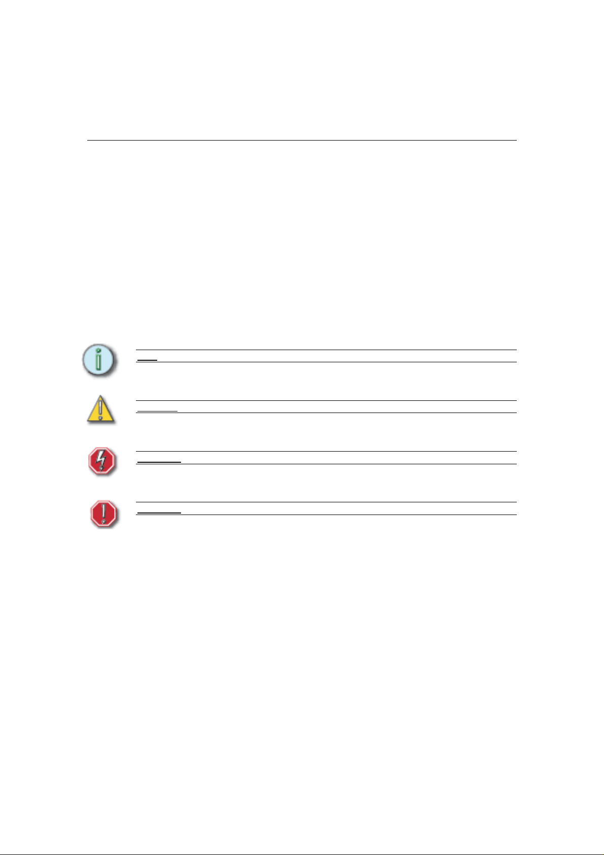
The following symbols are used in this manual to alert you to danger or important
information.
Note
: Provides important information about your installation
CAUTION
WARNING
WARNING
: Alerts you to important information relating to equipment performance or reliability.
: RISK OF ELECTRIC SHOCK! warns you when electricity may cause injury.
: warns you where there isd the possibility of other types of injury.
Table of Contents 1
Page 7
Chapter 1
Overview
System Components
The Matrix MkII dimming system consists of Matrix Mk.II racks, a Matrix Processor
per rack, and various dimmer module types. A module may contain an SCR dimmer
or a sine wave dimm er, but in addition, a module may contain only a circuit breaker,
a group of relays for switching either conventional lighting or HMI sources, dimmers
enhanced for Fluorescent loads, or may contain no electronics at all.
Matrix Mk.II Processor
The Matrix modules in each rack are managed by a rack Processor unit. The Matrix
Mk.II Processor stores the settings for each module in the rack, manages the data
lines into the rack, provides display for and access to the internal settings of each
channel in the rack's modules. Although each rack processor is central to the full
operation of Matrix Mk.II, each module's own processing capabilities ensure that
basic dimming facilities are maintained even if a major fault affects one of the dual
processing paths within the rack Processor. The dual processors are:
• Merge Processor: for managing data distribution to the dimmer modules
with direct inputs from DMX 1 and 2 (main data lines), Ethernet control data,
RS422 touch panels and 48 switched inputs via optional interfaces.
• Screen Processor: for setup, status reports and monitoring, with direct
inputs from DMX 1 and 2 (backup lines), Ethernet DimSTAT and RS485
DimSTAT.
The Processor serves as a real-time processor for incoming control signals and
transmits that information to the individual modules. It also monitors the system
status and reports any errors, both locally, on its own display panel and the affected
module's status LEDs, and remotely through the DimSTAT® network.
The Processor can be used to configure its rack within the system. Configuration and
error data can be accessed either locally at the Processor keypad, or by using the
DimSTAT network PC screen.
Networked Matrix Mk.II systems can be divided into separately configured
subsystems called zones. A zone would typically represent one auditorium or one
studio in a theatre or TV studio complex. There is no limit to the number of zones, but
the maximum number of Processors (i.e. racks in the system) is 255, which is
equivalent to 45,900 channels.
2
Page 8
The Matrix Processor has capacity to accept Ethernet data and regular DMX, to
choose two universes from the Ethernet data (for main and backup control lines A
and B), and to output DMX on XLR and RJ45 cat5 connections.
Matrix Mk.II Modules
The range of modules includes a choice of SCR rated at 3kW, 5kW or
12kW per channel with 400µS risetime chokes, Sine wave dimmers rated
at 1.25kW, 2.3kW, 3kW, 5kW or 12kW per channel, fluorescent modules
rated at 3kW or 5kW per channel, Non-Dim relays rated at 16A or 32A,
continuous supply modules rated at 16A, 32A or 63A, Solid-state switches
4kW HMI and 10kW 3-phase HMI non-dim relays with ignition detection.
Matrix Mk.II offers either 1,2,4 or 6 channel module options depending on
protection required. Generally, most 6 channel modules include one RCD
and 6 individual MCBs, and a 4 channel module has space for individual
RCBOs per channel.
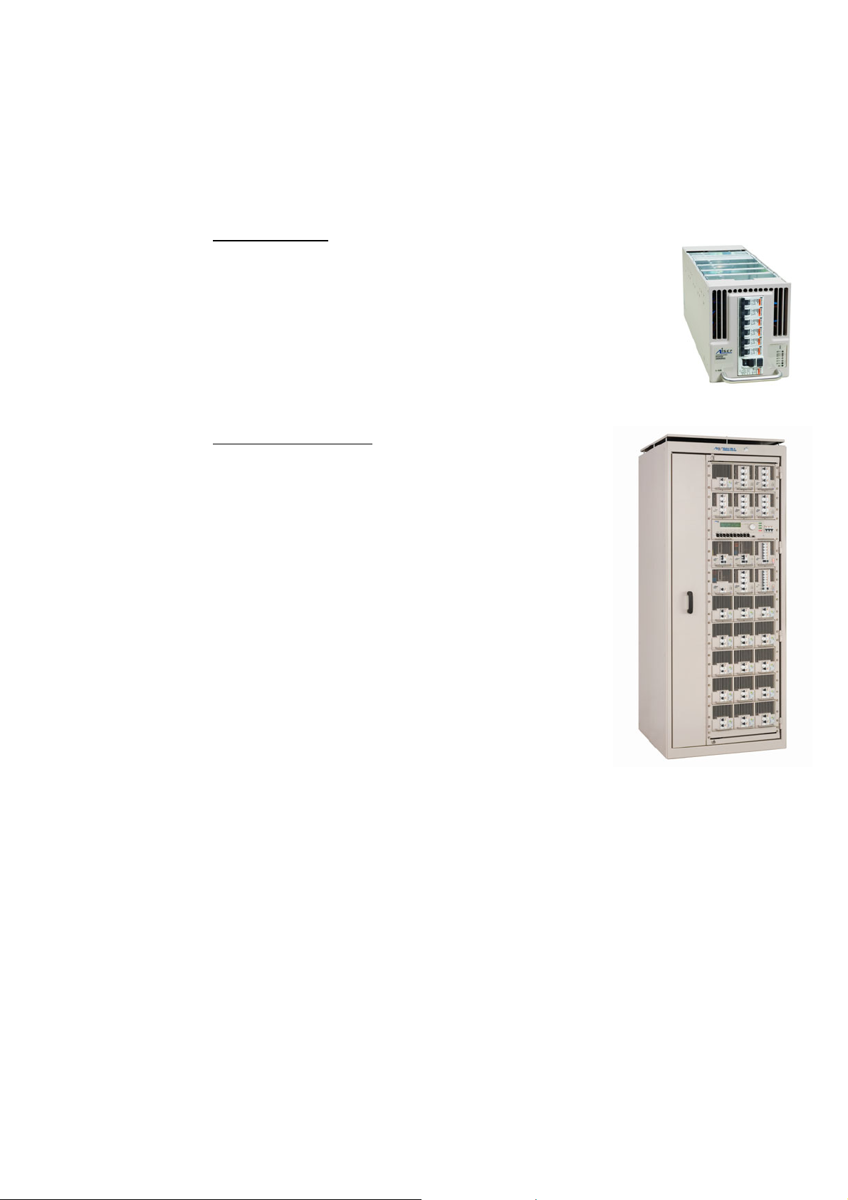
Matrix Mk.II dimmer cabinets
The range of Matrix Mk.II dimming cabinets includes 1600 and
2000mm heights, 600 or 800mm widths (800mm incorporates
a front access only swing frame), and a choice of wiring to
accommodate up to a maximum of 6 channels per module.
The 6-channel wiring version provides higher density, and
gives more flexibility for future expansion (it is compatible with
4-channel modules as well).
All terminals are high-specification spring loaded terminals for
4mm (3kW), 10mm (5kW) and 16mm (10kW) load
terminations.
There are 4 styles of cabinet for either 6-way or 4-way
configurations, with or without swing frame (front access only).
All are in standard ETC colours except where shown:
1600mm (h) x 800mm (w) x 800mm (d) swing frame,
4- or 6-way for 18 modules
2000mm (h) x 800mm (w) x 800mm (d) swing frame,
4- or 6-way for 18 modules
2000mm (h) x 800mm (w) x 800mm (d) swing frame,
4- or 6-way for 27 modules
1600mm (h) x 600mm (w) x 800mm (d) 6-way for 12 modules (RAL7035 light grey)
1600mm (h) x 600mm (w) x 800mm (d) 6-way for 18 modules (RAL7035 light grey)
2000mm (h) x 600mm (w) x 800mm (d) 6-way for 27 modules (RAL7035 light grey)
Table of Contents 3
Page 9
Matrix Mk.II Dimmer Monitoring Interface Overview
Each Matrix Mk.II power device in the system may be linked to a PC network using
DimSTAT® software for the purpose of remote control, set-up, status monitoring and
fault reporting. The system operates through a regular polling of dimmers, and if a
fault occurs, the report can be investigated from the PC in the first instance. The
network link is also used to upgrade software when appropriate.
DimSTAT provides a system-wide network, and operates on a host polling protocol
where the PC searches for connected dimmers at initiation, and then regularly polls
dimmers for data to display. If a fault occurs, the PC’s display instantly shows the
detail, and if the fault is cleared the system resets accordingly. Information displayed
includes: DMX start address per unit, DMX OK, line voltage, current per channel(with
most modules), dimmer curve, response time, max. setting, type of fault reported
(temperature, overload etc.), date and time of fault. It is possible to set the dimmer
curve, start address and pre-heat from DimSTAT software on the PC.
The operation and performance of the Matrix dimmer is monitored constantly and
comprehensively by the on-board data processors, and this information is available
on the LCD screen of the dimmer rack, and through DimSTAT. The parameters
measured and reported are:
a) DMX OK
b) DMX channel numbers
c) DMX levels
d) line voltage
e) current per dimmer (with suitable modules)
f) current per phase per rack
g) set frequency
h) dimmer curve
i) temperature per module
j) Cosine and ignition information for HMI modules
k) MCB / RCBO trip
4
Page 10

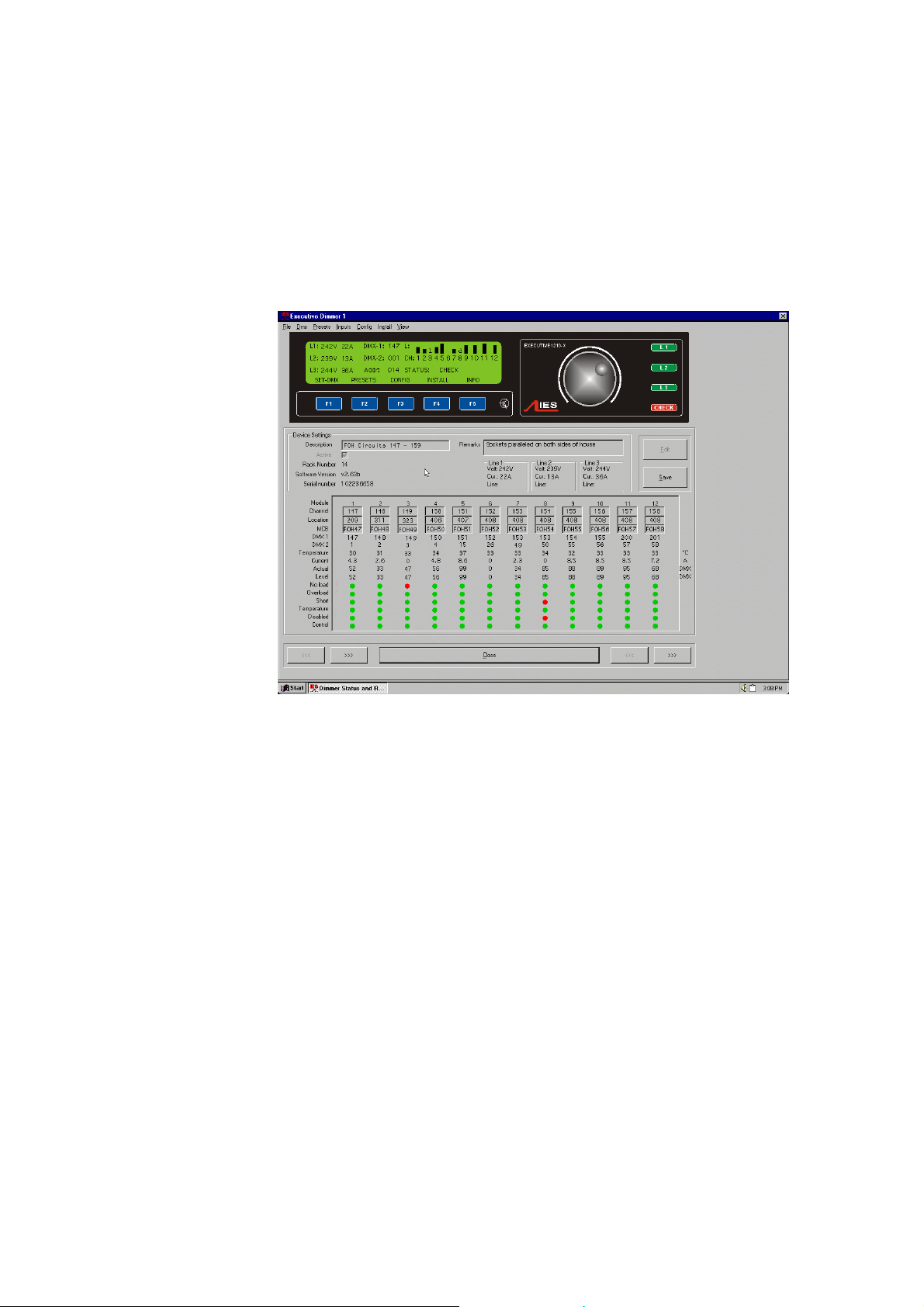
Normal operatio n
In normal rehearsal and performance situations, the home screen is displayed with
the list of all dimmers in the system. This display normally shows green indications if
the dimmers are operating correctly, grey if communication is lost, and red if a
reportable fault has been received.
If a dimmer reports a fault, click on the dimmer reference or icon, and DimSTAT will
switch to the main screen. The fault reported will be a red warning related to a
dimmer channel number in the list of faults.
DimSTAT offers interrogation facilities for each dimmer in the system at any time. To
check the mains supply voltage, load current, temperatures etc, simply select a
dimmer and view the data in the main screen.
Saving and recalling dimmer system configuration settings
DimSTAT is able to save the settings for all dimmers in the installation as a file. It
follows that many settings can be saved for different shows or variable conditions or
a change of hook-up. Before saving a configuration, remember to send all changed
data to the dimmers and check that the settings are correct. The data in DimSTAT
should be considered as a copy of the dimmer settings, and therefore the data
should be compared before and after disk transfers.
For details, refer to the DimSTAT operator’s handbook.
Matrix Dimming System Features
Modularity
Matrix Mk.II offers a wide range of plug-in power control devices including SCR and
Sine wave dimming, relay switch circuits and continuous power modules. Modules
can be exchanged safely with power applied, and modules with similar capacity can
be exchanged with each other (e.g. sine wave for SCR).
SCR dimmers
A wide choice of SCR dimmer modules are available with 400µS filters; 3kW, 5kW or
10kW capacity per channel; fluorescent versions with associated heater supply; a
choice of protection devices including MCB, RCD and RCBO.
Sine wave dimmers
Silent, low harmonic sine wave dimmer modules are available with options for
1250W, 2.3kW, 3kW, 5kW and 10kW capacity per channel; fluorescent versions with
associated heater supply; a choice of protection devices including MCB, RCD and
RCBO. Key features of Matrix Mk.II sine wave technology are:
Silence: Silent lamp filaments. Sine wave does not eliminate natural filament
resonance from a 50Hz mains supply, but it is no more noisy than if the lamp head is
connected to a maintained mains supply. There are no distractions for the audience
from lamps buzzing during a quiet moment. Radiated interference in audio and video
systems is no longer an issue, and signal cables can be safely positioned adjacent to
sine wave load cables with no effect on audio or video signal quality. Buzzing cables,
trunking, transformers and switchgear are no longer a problem with sine wave
dimming.
No reactive power: Creating less that 1% additional harmonic distortion and no 3rd
or 5th order harmonics, sine wave dimmers can actually be cheaper to run as the
reactive power demand is eliminated from supply bills. Costs are significantly less for
rewired venues, or new builds, because the usual requirement to overrate cables,
and switchgear by 40% is no longer an issue. That means a lot less copper and
Table of Contents 5
Page 11

expense. Smaller transformers and backup generators can be purchased, offering
great savings.
Environmentally friendly: Providing a pure sinewave, iSine technology avoids the
peak currents which stress filaments and also eliminates harmonic currents which
can affect other equipment and cause transformers to overheat. Cables and
generators also benefit - with a pure sinewave supply, the infrastructure does not
have to be overrated (usually 40% excess for normal dimming systems).
Versatile: The sine wave control is the most versatile dimming technology for
resistive and inductive loads. Almost any load which can be dimmed is dimmed
effortlessly with sinewave.
Non-Dim Switches
Relay switch modules are available for regular loads of either 16A or 32A with
options of MCB, RCD and RCBO. HMI switch modules are also available in 4kW and
10kW capacities with cosine measurement to monitor correct lamp ignition.
Distributed processing
Each plug-in dimmer module has integral processing to maintain basic operation
even if a processors fails in the Matrix Rack Processor unit.
New to Matrix Mk.II
Higher density
The original Matrix offered a maximum of 162 x 2.5kW, 108 x 5kW or 27 x 10kW (or
mixtures of all three dimmer ratings). The new Matrix Mk.II is designed around a 4U
high module (44mm taller than previous modules) with space for up to 6 dimming
channels per module.
Increased economy
By increasing the dimmer count in each module to a maximum of 6, the per dimmer
cost can reduce for high-density installations.
Greater choice of channel ratings
The enlarged module size now allows for a rating upgrade from 2.5kW per channel to
3kW for SCR and sine wave. Sine wave dimmers are also available in 1250W,
2.3kW, 5kW and 12kW ratings.
Improved efficiency
Even though the previous Matrix sine wave dimmers were very efficient for their type
(typically 97%), the new design includes a frequency boost to improve efficiency to
98%, better than many traditional SCR dimmers.
6
Page 12
Chapter 2
Basic Navigation
This section covers the functions and configuration of the Matrix Mk.II processor. It is
possible to password protect areas of the configuration facility, and this is explained
later, but for simplicity the details given here do not require password entry.
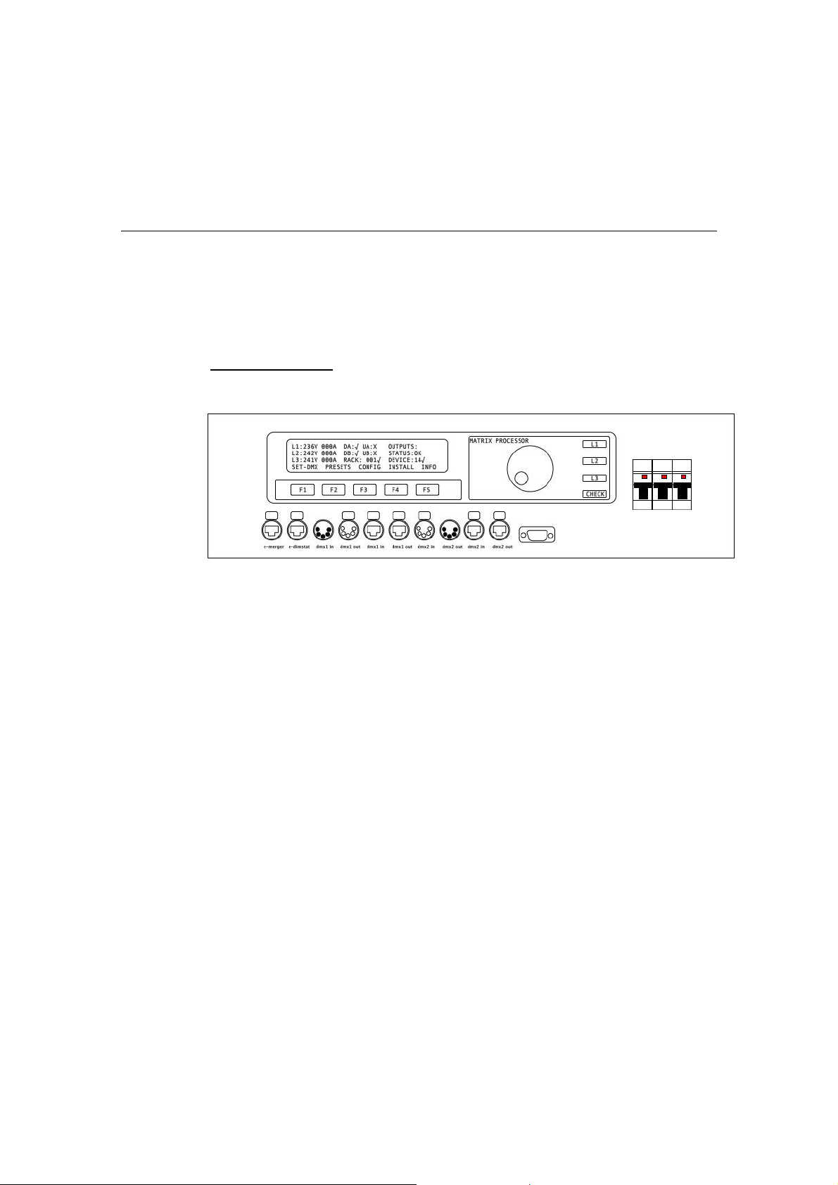
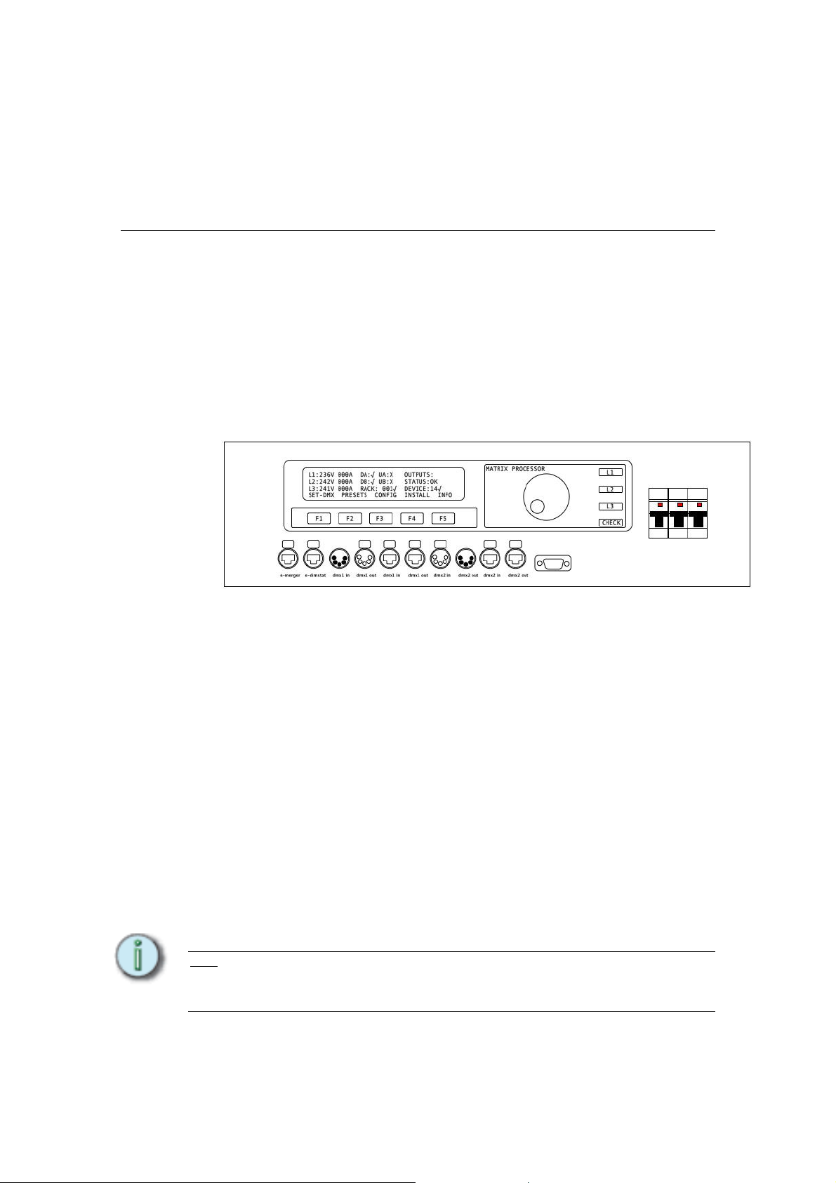
Processor User Interface
It is possible to set and view all of the performance and control characteristics,
measurements and status reports created by the dimmer from the Processor’s front
panel LCD screen.
The screen is a 40 x 4 character backlit LCD which provides visual feedback of
status and settings, and functional descriptions of the five soft-designated push
buttons (F1-F5) beneath the screen.
Additionally, a rotary encoder provides the input interface to adjusting levels and
choosing the dimmer’s internal characteristics and performance options.
Three green LED bar indicators L1, L2 and L3 light when three phases are present,
and a CHECK red led indicator illuminates when the processor has identified any
error which is unresolved. Self-resetting faults cause the CHECK light to extinguish
when the fault has cleared.
Three MCBs are located to the right of the panel which supply 3-phases to the
Processor for internal electronics power supplies. An internal phase selector ensures
that power is available to the processor even if two of the three phases fail.
Optional local connections for data are included below buttons F1-F5. These include
Ethernet in, DMX in and through, and a RS422 serial connector. The data signals
may be accessed at the front panel connection strip, or in the case of rear access
only cabinets, via the rear connections. The connections are made to either front or
rear by two RJ45 Ethernet jumper cables, which can be clearly seen when the
processor is withdrawn from the cabinet.
Note
: All of the following instructions relate to manual operation using the processor’s local
controls. If specific device has to be interrogated (i.e. for channel-specific features) activate the
required device by pressing its front panel access button (the technology logo above the
device’s column of LEDs).
Table of Contents 7
Page 13

The processor’s functionality is available with DimSTAT and is generally faster and
easier to perform through DimSTAT using a PC using shortcuts to the Matrix’s setup
features, but for the purpose of this handbook the differences in using DimSTAT are
not described in detail and have to be interpreted from the DimSTAT screen. See the
DimSTAT handbook for further details.
Basic use of the Processor user interface:
The ‘soft’ keys F1 – F5 are automatically labelled as the menu context changes. For
the home page shown above, the menus refer to:
• Use F1 to access the DMX settings to set the DMX address for each
dimmer channel in each module (device). Navigate the menu by rotating the
encoder wheel either clockwise or counter-clockwise.
• Use F2 to access the internal preset settings to set and store dimmer
presets, preset in/out timings, DMX fail backup presets. Navigate the menu
by rotating the encoder wheel either clockwise or counter-clockwise.
• Use F3 to access the dimmer configuration menus to set all the custom
channel attributes – min, max levels, fade time T-in, T-out, dimmer curve,
non-dim operation I/O, priority, phase control, start mode, tune lamp
• Use F4 to access the basic installation settings to set supply parameters,
Ethernet and DimSTAT addresses, no. of devices, change passwords, view
channel data live, and provide access to general settings for method of
channel and DMX addressing, DMX preferences, voltage regulation, current
limitation, lamp saving and lamp tuning and to test the ventilation system
and check firmware.
• Use F5 for system reports. If there are no faults indicated by the CHECK
indicator, the INFO button shows the software version and nominal voltage
and current. If a fault is indicated, the error report is displayed for
interrogation and reset.
Details of each menu tree are shown in Appendi x A.
PASSWORDS Note
do not refer to the entry of passwords. Passwords are included to prevent accidental or casual
access to the SET-DMX, PRESETS, CONFIG and INSTALL menu trees. The passwords are 4digit numbers with a factory default of 0000 (no password necessary). A service code of 3415 is
embedded and may be used if the passwords are forgotten and for service-protected menus. It
is possible to have the same password throughout, or separate passwords for each menu tree.
If any of the protected menus is selected, the subsequent screen requests a password. This is
achieved by pressing the relevant <<<< and >>>> buttons to select the digit, and using the
rotary encoder to enter the number.
The initial power-up display shows the general setting parameters with the software
version. After a few seconds, this screen changes to the ‘home’ screen which
displays channel levels (bar graphs at the top right), the measured line voltages and
currents, and the status of the dimmers and DMX signals from device 1. The number
of bar graphs shown relates to the load selection of the device being monitored.
L1: 245V-38A DA-X UA-X OUTPUTS. _ ||| _ |||
L2: 247V-14A DB-X UB-X STATUS: OK
L3: 242V-20A RACK : 05 X DEVICE: 01X
SET-DMX PRESETS CONFIG INSTALL INFO
: For clarity, the following sections which describe programming activities
8
Page 14
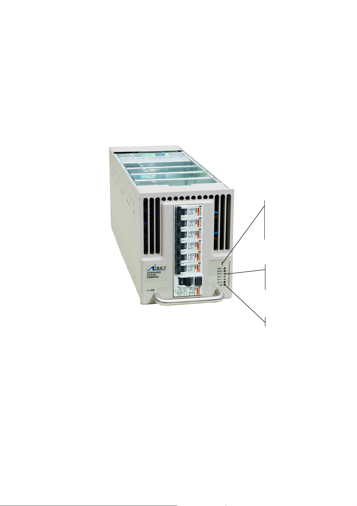
Dimmer Mod ule User Interface
p
Local control for each dimmer module is included within the Processor, and no direct
access is required with the module to view and adjust settings. However, each
module includes slave indicators and an interrogation control button for convenience.
When the interrogate button is pressed (the coloured disc in the logo) the Processor
LCD panel and controls are routed to the selected module.
Each front panel has an LED per output channel to indicate when there is an output,
or if there is a fault with a channel, and when power is applied to the module, the blue
'ON' LED is lit.
Press the coloured
disc of the logo for the
module's activation
button to interrogate
this module via the
Processor LCD.
Individual status LED per channel.
Green = Output OK
Red = fault
None = no out
ut
Table of Contents 9
Page 15

Chapter 3
Configuration Procedures
Initial settings
Some settings for the Matrix rack are made during installation only, and many of the
channel configuration settings may only rarely be changed after the commissioning
period. Some other settings may be changed regularly on a show-by-show basis
(e.g. non-dim operation).
The initial settings required are to program the processor to search for a particular
number of Matrix ‘devices’ in each rack, and to choose the power ratings for each
Matrix device.
To check the number of modules (devices) programmed for use in the rack:
This menu defines the number of modules in use in the rack, and is set at the time of
installation.
1. Select INSTALL from the home screen
2. Press DOWN or UP or use the rotary encoder to choose SELECT NUMBER OF
DEVICES menu. Press SELECT.
3. The screen shows
SELECT NUMBER OF DEV ICES
DEVICES: 012
CANCEL ENTER
4. Use the rotary encoder to select the number of Matrix devices (the plug-in
modules) in the rack.
5. Press ENTER (to record the changes and return to the home screen) or CANCEL
(to leave the previous settings unchanged, and return to the home screen).
To select the load ratings of devices:
CAUTION: This feature sets the configuration of each dimmer module in the rack to define the
number of dimmers to be addressed and anticipated load and current measurements. If the
setting is incorrect, e.g. a 2 x 5kW dimmer is set up as a 1 x 12kW dimmer, the result will be two
adjacent channels operating as one.
This function is only available for the modules 4x3kW and 2x5kW sine wave
1. Activate a module (e.g. 12) by pressing its front panel access button (the
technology logo above the device’s column of LEDs). Or select the device with
the rotary encoder
2. Press DOWN or UP or use the rotary encoder to choose LOAD SELECTION
menu in the . Press SELECT.
3. The screen shows:
10
Page 16

SELECT LOAD SELECTIO N DEVICE 12
LOAD: 4 x 2.5KW
EDIT CANCEL SAVE
5. Press EDIT.
6. Use the rotary encoder to select the channel configuration of the device:
4 x 3kW
2 x 5kW
1 x 12kW
7. Press SAVE (to record the changes and return to the home screen) or CANCEL
(to leave the previous settings unchanged, and return to the home screen).
8. Repeat for other devices by pressing their access buttons in sequence.
Setup schemes for channels and DMX
Matrix Mk.II dimmers have the capacity to store performance characteristics for each
dimmer channel individually. However, in some instances this can lead to
unnecessary and time-consuming programming, and so the option is included to
choose a data entry scheme for all channels in the device together, or for individual
data entry as required or as dictated by the system. This feature is independent of
the choice of DMX numbering scheme, thus the dimmers may have individual
characteristics, but with consecutive DMX addresses. This step, and 2.3 DMX setup,
should be performed before other channel-specific programming activities.
To change the dimmer characteristics set-up scheme:
1. Select INSTALL from the home screen
2. Press DOWN or UP or use the rotary encoder to choose GENERAL SETTINGS
menu. Press SELECT.
3. Press DOWN or UP or use the rotary encoder to choose CONFIG CHANNEL
menu. Press SELECT.
4. The screen shows
GENERAL SETTINGS
CONFIG CHAN: [JOI NED]
CANCEL SAVE
5. Use the rotary encoder to select either INDIVIDUAL (for different individual
channel parameters) or JOINED (for all channels in the device to have the
same characteristics).
6. Press SAVE (to record the changes) or CANCEL (to leave the previous settings
unchanged, and return to the previous page).
Note:
the quickest method of programming the characteristics of a specific device is to use
DimSTAT. If local control is preferred, press t h e lo go button to sw itch the processor directly to
the relevant device.
Table of Contents 11
Page 17

DMX programming
Each channel in a Matrix device is assigned a DMX channel number from either
DMX-1 or DMX-2 signal inputs. The two numbers can be the same or different, as
required, and a feature is provided to set sequential number groups (‘Start’
addressing) instead of individual settings.
When programming a new dimmer device, IT IS IMPORTANT TO SET THE DMX
Note:
ADDRESSING SCHEME before the individual characteristics are set, as a later change can
reset previously recorded individual channel characteristic settings.
To set up DMX addressing scheme:
1. Select INSTALL from the home screen
2. Press DOWN or UP or rotate the encoder to choose GENERAL SETTINGS
menu. Press SELECT.
3. Press DOWN or UP or rotate the encoder to choose DMX ADDRESS. Press
SELECT, and the screen shows:
GENERAL SETTINGS
DMX ADDRESS [INDIV IDUAL]
CANCEL SAVE
4. Use the rotary encoder to select either INDIVIDUAL (for individual DMX
addresses in each device) or START (one DMX address only is entered for the
first channel in the device, with other channels following in sequential order).
5. Press SAVE to leave the menu and to record the changes or CANCEL (to leave
the previous settings unchanged and return to the previous screen).
Note:
As there are two DMX lines, both DMX-1 and DMX-2 follow the same scheme. It is not
possible to have one line using a start address, and the other using individual numbers.
To set-up DMX addresses:
1. First set the DMX scheme as described above (either individual or start
address).
2. Activate the required device (e.g. device 12) by pressing its front panel access
button (the technology logo above the device’s column of LEDs).
3. From the home screen, select SET-DMX, and to change a setting, press
ENTER
4. If INDIVIDUAL address option is in use, the screen is similar to this:
SELECT DMX ADDRESS DEVICE 12
CHANNEL 1
DMX 1 ADDRESS 005
DOWN UP EDIT CANCEL SAVE
5. If INDIVIDUAL has been selected, use the rotary encoder to select the address
needed for the first dimmer channel and move to other channels by pressing
DOWN or UP repeatedly and adjust DMX addresses accordingly. The rotary
12
Page 18

encoder will increment the address number clockwise, and reduce the number
anti-clockwise, with a roll-over at the 512-0 point.
6. If START has been selected, only one number per DMX line is permitted. This
is the number for dimmer channel 1 in the first device, and the remaining
dimmers are automatically addressed in sequential order.
7. Press the DOWN key to activate DMX-2, and repeat for the second DMX line.
Note
: DMX address 000 deselects the channel from operation with the relevant DMX line. Both
DMX lines have valid DMX numbers from 001 - 512. If higher dimmer numbers are used by the
control desk, the number has to be rationalised to a base of 512.
DMX A/B arbitration
In the case where a dimmer has two DMX channel numbers selected, and both
signals are active, the dimmer will normally respond to the highest level of the two
signals (HTP). If one DMX number is set to 000, the dimmer will not respond to
channel data from the relevant DMX line.
This feature is used to provide segregation and zoning for two control systems, or for
separating channel numbers between 513 and 1024 using a pair of DMX lines. If one
DMX line is set to 'Master' it takes exclusive control until the DMX fails, at which time
control is transferred to the other DMX line.
: When the channel status is being viewed at the dimmer device or remotely by DimSTAT,
Note
the term ‘actual’ DMX level is used. This is a display of the result of any internal arbitration of
levels from either DMX-1, DMX-2, the internal ‘manual preset’ level, or the level set by a
programmable preset memory. Thus if DMX-1 is 56%, DMX-2 is 75% and preset 3 is set to
95%, the Actual DMX level is shown as 95%.
To set up a DMX backup condition
Matrix is equipped with a choice of responses to the failure of either DMX signals 1 or
2. The dimmers can be set to hold their last DMX level, fade to zero over 5 seconds,
or fade to a preset memory setting. This choice is available per DMX line and dimmer
device.
1. Select INSTALL from the home menu.
2. Press DOWN or UP or use the rotary encoder to choose GENERAL
SETTINGS.
3. Press DOWN or UP or use the rotary encoder to choose DMX-1 FAIL menu.
Press SELECT.
GENERAL SETTINGS
DMX-1 FAIL: [HOLD]
CANCEL SAVE
4. Press EDIT and use the rotary encoder to select one of the 3 options available:
RESET: fades all dimmers to zero after 5 seconds
HOLD: maintains the last valid DMX levels indefinitely until DMX is restored
Table of Contents 13
Page 19

BACKUP: fades to dimmer levels set-up through t he PR ESETS memory facility
5 Press SAVE to leave the menu and record the changes or CANCEL (to leave
the previous settings unchanged and to return to the previous screen).
6. Repeat the procedure for DMX-2.
Note
: If BACKUP has been set, do not forget to pre-set the relevant DMX backup states.
To set-up DMX Backup preset:
1. Select PRESETS. from the home menu
2. Press DOWN or UP or use the rotary encoder to choose DMX BACKUP menu.
Press SELECT.
3. The screen provides the following information:
SELECT DMX BACKUP DEVICE 12
CHANNEL 1
DMX-1 ADDRESS 005
DOWN UP EDIT CANCEL SAVE
4. Press EDIT and using the <<<< and >>>> buttons, choose the channel level to
be adjusted [enabled when square brackets are shown] and set the level by
using the rotary encoder.
5. Use the UP or DOWN button to address either DMX-1 or DMX-2 and repeat the
above procedure.
6. Press ENTER to leave the menu, then either SAVE (to record the changes) or
CANCEL (to leave the previous settings unchanged).
14
To set-up a DMX Minimum reset
In order to reduce dynamic filament noise in 120V Par lamps or to increase the rate
of response of high wattage filaments, it is sometimes necessary to use a low
preheat level. DMX minimum reset is an automatic means to reduce energy
consumption by switching off any preheat levels when DMX is not present (i.e. when
the control desk is switched off, but the dimmers remain on).
1. Select INSTALL from the home menu.
2. Press DOWN or UP or use the rotary encoder to choose GENERAL SETTINGS
menu. Press SELECT.
3. Press DOWN or UP or use the rotary encoder to choose DMX MINIMUM
RESET menu. Press SELECT.
GENERAL SETTINGS
DMX MINIMUM RESET: [OFF]
DOWN UP CANCEL SAVE
4. Use the rotary encoder to choose either ON (active) or OFF (disabled).
Page 20

5. Press SAVE to record the change or CANCEL (to leave the previous settings
unchanged and return to the previous screen).
DMX lamp features
Matrix sine wave technology offers two additional features to enhance lamp
performance; Lamp Tuning and Lamp Saver.
Lamp Tuning is a global feature which provides a load learning facility whereby the
Matrix dimmer records the current after the lamp has been set to between 90-100%
for 3 seconds. This data is then used to ‘tune’ the dimmer curve to ensure that all
lamps respond the same, and there is not an inconsistency in dimming between a
25W lamp and a 5kW lamp on different dimmers.
Lamp Saver is a global feature which only applies preheat if the channel has been
used after power up.
To set-up a DMX Lamp Tuning
1. Select INSTALL from the home menu.
2. Press DOWN or UP or use the rotary encoder to choose GENERAL SETTINGS
menu. Press SELECT.
3. Press DOWN or UP or use the rotary encoder to choose DMX LAMP TUNING
menu. Press SELECT.
GENERAL SETTINGS
DMX LAMP TUNING: [ON]
CANCEL SAVE
4. Use the rotary encoder to choose either ON (active) or OFF (disabled).
5. Press SAVE to record the change or CANCEL (to leave the previous settings
unchanged and return to the previous screen).
To set-up a DMX Lamp Saver
1. Select INSTALL from the home menu.
2. Press DOWN or UP or use the rotary encoder to choose GENERAL SETTINGS
menu. Press SELECT.
3. Press DOWN or UP or use the rotary encoder to choose DMX LAMPSAVER
menu. Press SELECT.
GENERAL SETTINGS
DMX LAMPSAVER: [ON]
CANCEL SAVE
4. Use the rotary encoder to choose either ON (active) or OFF (disabled).
5. Press SAVE to record the change or CANCEL (to leave the previous settings
unchanged and return to the previous screen).
Table of Contents 15
Page 21

Network settings
This section extends the data setup procedure to cover the network setup of Matrix
Mk.II dimmers on a DimSTAT and Ethernet network. Control via Ethernet is an
option, and if used, DimSTAT is transmitted within the Ethernet network. If Ethernet
is not used (i.e. dimmer control is via direct DMX connections) DimSTAT is
transmitted using the two spare cores of the DMX-512 cabling system (pins 4 and 5).
Note that one of the benefits of using Ethernet is that the data rate of DimSTAT is
much faster than if DMX cabling scheme is used. Typical data rates using direct
DimSTAT over DMX cables is 56kB/s whereas with Ethernet it can be 10MB/s,
100MB/s or 1GB/s depending on the cabling scheme.
DimSTAT address
The PC address shown on the home screen as RACK: XX is the unique number
which is used by DimSTAT™ to identify each dimmer location or peripheral for the
purpose of reporting status information and for transferring data between dimmer
devices and the PC. If a dimmer device is removed from the rack, and replaced by
another device DimSTAT will prompt for an update of configuration information when
power is restored.
This is done when the RACK number is entered, and DimSTAT identifies the new
device on the network, prompting the operator to download the previous
characteristics file from the PC to the dimmer device. The RACK number is
associated with a unique factory serial number which is permanently stored in the
dimmer. This is because if a different dimmer device is used with the same RACK
number as its predecessor, the DimSTAT program compare serial number and
RACK address, notes the difference and thus will prompt the system to download the
previous dimmer set-up.
To set-up a serial address:
1. Select INSTALL from the home menu
2. Press DOWN or UP or use the rotary encoder to choose SELECT PCDIMSTAT PARAMETERS menu. Press SELECT.
3. The screen shows:
SELECT PC-DIMSTAT PARAMETERS
ADDRESS: [004]
CANCEL ENTER
4. Use the rotary encoder to choose the address number (which can be set
between 000 and 255).
5. Press ENTER to leave the menu, then either SAVE (to record the changes) or
CANCEL (to leave the previous settings unchanged).
Ethernet
Matrix Mk.II dimmers are prepared for use with Ethernet data distribution for dimmer
signals and DimSTAT communications. Protocols included are ETCnet2, AVAB,
ArtNet and ACN/RDM. Two sets of addresses need to be set up: IP, subnet and
gateway addresses for the dimmers and similar settings for the merger.
To set-up the dimmer IP address:
1. Select INSTALL from the home menu
16
Page 22

2. Press DOWN or UP or use the rotary encoder to choose ETHERNET SETUP
menu. Press SELECT.
3. This accesses the Ethernet menu tree. Press DOWN or UP or use the rotary
encoder to choose IP ADDRESS menu. Press SELECT.
4. The screen shows:
SELECT ETHERNET ADDRESS
AAA BBB CCC DDD
IP ADDRESS [010] 001 002 002
<<<<< >>>>>> EDIT CANCEL SAVE
5. Use the rotary encoder to choose the address number and press >>>> or <<<<
to tab other 3-digit groups.
6. Press ENTER to leave the menu, then either SAVE (to record the changes) or
CANCEL (to leave the previous settings unchanged).
To set-up the dimmer subnet mask:
1. Select INSTALL from the home menu
2. Press DOWN or UP or use the rotary encoder to choose ETHERNET SETUP
menu. Press SELECT.
3. This accesses the Ethernet menu tree. Press DOWN or UP or use the rotary
encoder to choose SUBNET MASK menu. Press SELECT.
4. The screen shows:
SELECT ETHERNET SUBNET MASK
AAA BBB CCC DDD
SUBNET MASK [255] 255 255 000
<<<<< >>>>>> EDIT CANCEL SAVE
5. Use the rotary encoder to choose the address number and press >>>> or <<<<
to tab other 3-digit groups.
6. Press ENTER to leave the menu, then either SAVE (to record the changes) or
CANCEL (to leave the previous settings unchanged).
To set-up the dimmer gateway address:
1. Select INSTALL from the home menu
2. Press DOWN or UP or use the rotary encoder to choose ETHERNET SETUP
menu. Press SELECT.
3. This accesses the Ethernet menu tree. Press DOWN or UP or use the rotary
encoder to choose GATEWAY ADDRESS menu. Press SELECT.
4. The screen shows:
Table of Contents 17
Page 23

SELECT ETHERNET GATEWAY ADDRESS
AAA BBB CCC DDD
IP ADDRESS [010] 001 001 001
<<<<< >>>>>> EDIT CANCEL SAVE
5. Use the rotary encoder to choose the address number and press >>>> or <<<<
to tab other 3-digit groups.
6. Press ENTER to leave the menu, then either SAVE (to record the changes) or
CANCEL (to leave the previous settings unchanged).
To set-up the merger IP address:
1. Select INSTALL from the home menu
2. Press DOWN or UP or use the rotary encoder to choose MERGER ETHERNET
MENU. Press SELECT.
3. This accesses the Merger’s Ethernet menu tree. Press DOWN or UP or use the
rotary encoder to choose IP ADDRESS menu. Press SELECT.
4. The screen shows:
SELECT ETHERNET ADDRESS
AAA BBB CCC DDD
IP ADDRESS [010] 001 002 002
<<<<< >>>>>> EDIT CANCEL SAVE
5. Use the rotary encoder to choose the address number and press >>>> or <<<<
to tab other 3-digit groups.
6. Press ENTER to leave the menu, then either SAVE (to record the changes) or
CANCEL (to leave the previous settings unchanged).
To set-up the merger subnet mask:
1. Select INSTALL from the home menu
2. Press DOWN or UP or use the rotary encoder to choose MERGER ETHERNET
SETUP menu. Press SELECT.
3. This accesses the Merger’s Ethernet menu tree. Press DOWN or UP or use the
rotary encoder to choose SUBNET MASK menu. Press SELECT.
4. The screen shows:
SELECT ETHERNET SUBNET MASK
AAA BBB CCC DDD
SUBNET MASK [255] 255 255 000
<<<<< >>>>>> EDIT CANCEL SAVE
18
Page 24

5. Use the rotary encoder to choose the address number and press >>>> or <<<<
to tab other 3-digit groups.
6. Press ENTER to leave the menu, then either SAVE (to record the changes) or
CANCEL (to leave the previous settings unchanged).
To set-up the merger gateway address:
1. Select INSTALL from the home menu
2. Press DOWN or UP or use the rotary encoder to choose MERGER ETHERNET
SETUP menu. Press SELECT.
3. This accesses the Merger’s Ethernet menu tree. Press DOWN or UP or use the
rotary encoder to choose GATEWAY ADDRESS menu. Press SELECT.
4. The screen shows:
SELECT ETHERNET GATEWAY ADDRESS
AAA BBB CCC DDD
IP ADDRESS [010] 001 001 001
<<<<< >>>>>> EDIT CANCEL SAVE
7. Use the rotary encoder to choose the address number and press >>>> or <<<<
to tab other 3-digit groups.
8. Press ENTER to leave the menu, then either SAVE (to record the changes) or
CANCEL (to leave the previous settings unchanged).
To set-up the merger universes:
1. Select INSTALL from the home menu
2. Press DOWN or UP or use the rotary encoder to choose MERGER ETHERNET
SETUP menu. Press SELECT.
3. This accesses the Merger’s Ethernet menu tree. Press DOWN or UP or use the
rotary encoder to choose NET, UNIVERSE A menu. Press SELECT.
4. The screen shows:
MERGER LOGIC NET, UNIVERSE A
NET UNIVERSE
0 000
EDIT CANCEL SAVE
5. Press EDIT and use the rotary encoder to choose the required logical net and
universe.
6. Press ENTER to leave the menu, then either SAVE (to record the changes) or
CANCEL (to leave the previous settings unchanged).
7. Repeat for Universe B.
Table of Contents 19
Page 25

Channel settings
This section describes the individual settings for each channel in the Matrix rack.
Individual dimmers may be setup to have specific characteristics for a particular
application, such as maximum and minimum level settings, non-dim operation,
default fade in and fade out times etc.
Maximum & Minimum levels
It is possible to affect the output range of a dimmer by setting a minimum level and
(or) a maximum level. A minimum level is used to provide a pre-heat to warm up
lamp filaments, whereas the maximum level is used to limit power and extend lamp
life. Minimum levels between 0% to 29.9% may be set, and maximum levels may be
set from 100% down to 30%.
Factory default levels are 0% for minimum and 100% for maximum. One common
use for a reduced maximum level to control 110V lamps. However, for this situation,
the 110V dimmer curve is recommended as it produces a smoother control over the
whole range of intensity. If used, this result of using this feature should be checked in
comparison with other lamps in the rig to ensure uniformity of response.
To set-up max. and min levels:
1. Select CONFIG. from the home menu, and press EDIT.
2. The screen shows the individual channel number (or ALL if the dimmer set-up
scheme copies characteristics to all dimmers in the device) as follows:
CONFIGURE CHANNEL PARAMETERS
CH MIN% MAX% T-IN T-OUT CURVE I/O PRIOR
ALL [000.0] 100.0 00.02 00.02 LIN NO NO
EDIT CANCEL SAVE
Setting options are :
MIN: minimum level from 000 to 100%.
MAX: maximum level from 000 to 100%.
3. Press EDIT and using the <<<< and >>>> buttons, choose MIN% or MAX%
[enabled when square brackets are shown] and set it to the required number
using the rotary encoder.
4. Using the UP and DOWN buttons to address other channel numbers (unless all
dimmers are being set-up together).
5. Press ENTER to leave the menu, then either SAVE (to record the changes) or
CANCEL (to leave the previous settings unchanged).
Response time
Each dimmer has two timings associated with it which control the minimum time to
fade in and out, and are called T-IN and T-OUT. These times are referred to as
‘response times’ and are used to protect the lamp filaments and for reducing surges
in the system. The default times are currently zero seconds (for the fastest
response). Values recommended are 0.00s for a 2kW load, 0.05s for a 5kW load,
and 0.1s for a 10kW load
To set-up response times:
1. Select CONFIG. from the home menu, and press EDIT.
2. The screen shows the individual channel number (or ALL if the dimmer set-up
scheme copies characteristics to all dimmers in the device) as follows:
20
Page 26

CONFIGURE CHANNEL PARAMETERS
CH MIN% MAX% T-IN T-OUT CURVE I/O PRIOR
ALL 00 100 [00.05] 00.05 LIN NO NO
EDIT CANCEL SAVE
Setting options are from 00.00s to 99.99s.
Note
: 0 seconds should not be used with TV-type high wattage lamps, where the minimum
recommended is 0.05s. Faster response times should be used with care, and with lower
wattage loads.
3. Press EDIT and using the <<<< and >>>> buttons, choose T-IN or T-OUT
[enabled when square brackets are shown] and set it to the required time using
the rotary encoder.
4. Using the UP and DOWN buttons to address other channel numbers (unless all
dimmers are being set-up together).
5. Press ENTER to leave the menu, then either SAVE (to record the changes) or
CANCEL (to leave the previous settings unchanged).
Dimmer curves
Dimmer curves (dimmer laws) are used to adjust the relationship between control
level and light output. This enables the dimmer to be fine-tuned to accommodate the
preferences of a live audience or a television camera. There are 8 fa ctory standard
dimmer laws, and a provision for a further 26 custom selectable curves in later
software releases. The factory default law (0) is Linear Law. The list of dimmer
curves is as follows:
0 = linear relationship (standard)
1 = BBC specification
2 = S-Law
3 = inverted (control = zero, dimmer = full etc.)
4 = Fluorescent (minimum 50%)
5 = Fluorescent (minimum 30%)
6 = Linear (offset at 50%)
7 = Pulse effect (light switches on and off as the control fades up and down)
8 = Solid state switch
9 = 2kW linear curve
10 - 15 custom programmable via DimSTAT (future expansion)
To select a dimmer curve:
1. Select CONFIG. from the home menu, and press EDIT
2. The screen shows the individual channel number (or ALL if the dimmer set-up
scheme copies characteristics to all dimmers in the device) as follows:
Table of Contents 21
Page 27

CONFIGURE CHANNEL PARAMETERS
CH MIN% MAX% T-IN T-OUT CURVE I/O PRIOR
ALL 00 100 00.05 00.05 [LIN] NO NO
EDIT CANCEL SAVE
3. Use the <<<< and >>>> buttons, choose CURVE [enabled when square
brackets are shown] and set it to the response required.
4. Using the UP and DOWN buttons to address other channel numbers (unless all
dimmers are being set-up together).
5. Press ENTER to leave the me nu, t hen either SAVE (to record the changes) or
CANCEL (to leave the previous settings unchanged).
Non-Dim operation
Any Matrix dimmer channel may be set to switch on and off rather than dim, and in
this way are used for many other functions such as switching power to working lights,
non-dim and auxiliary circuits.
To select a channel to operate as a non-dim switch:
1. Select CONFIG. from the home menu, and press EDIT
2. The screen shows the individual channel number (or ALL if the dimmer set-up
scheme copies characteristics to all dimmers in the device) as follows:
CONFIGURE CHANNEL PARAMETERS
CH MIN% MAX% T-IN T-OUT CURVE I/O PRIOR
ALL 00 100 00.05 00.05 LIN [NO] NO
EDIT CANCEL SAVE
3. Use the <<<< and >>>> buttons, choose I/O [enabled when square brackets
are shown] and set it to either NO for dimmer operation, or YES for a non-dim
4. Using the UP and DOWN buttons to address other channel numbers (unless all
dimmers are being set-up together).
5. Press ENTER to leave the me nu, t hen either SAVE (to record the changes) or
CANCEL (to leave the previous settings unchanged).
Maximum current
Each Matrix device has a facility to measure each phase current and to restrict the
operation of the dimmers on that phase to ensure the maximum current set is not
exceeded. This operates as a maximum demand protection system, and reduces the
levels of all dimmers on the phase which is exceeding the preset current.
However, to eliminate a key light from reducing during a performance, it is possible to
prioritise the channels which will reduce in intensity to ensure the maximum demand
is not exceeded. This is achieved by setting the dimmer channel to “priority”, and it
will then ignore any instruction to reduce level if the maximum demand is exceeded.
To set-up maximum current levels:
1. Select INST ALL from the home menu
2. Press DOWN or UP or use the rotary encoder to choose SELECT LINE
PARAMETERS menu. Press SELECT.
22
Page 28

3. The screen shows:
SELECT LINE PARAMETERS
VOLTAGE CURRENT FREQUENCY
NOMINAL 235 [43] 50 Hz
<<<< >>>> CANCEL SAVE
4. Press EDIT and using the << << a nd >>>> buttons, choose CURRENT and
enter the maximum current limit per phase using the rotary encoder.
5. Press ENTER to leave the me nu, t hen either SAVE (to record the changes) or
CANCEL (to leave the previous settings unchanged).
To set-up priority channels:
It is possible to prioritise the channels which will reduce in intensity to ensure the
maximum demand is not exceeded when maximum current is selected above. This is
achieved by setting the dimmer channel to “priority”, and it will then ignore any
instruction to reduce level if the maximum demand is exceeded.
1. Select CONFIG. from the home menu
2. The screen shows the individual channel number (or ALL if the dimmer set-up
scheme is all together) with a list of all available channel characteristics
including PRIOR (priority) which is to the right of the screen, and is accessible
when >>>> is pressed repeatedly:
CONFIGURE CHANNEL PARAMETERS
CH MAX% T-IN T-OUT CURVE I/O PRIOR PHASE
ALL 100 00.05 00.05 LIN NO [NO] OFF
<<<< >>>> CANCEL SAVE
3. Use the <<<< and >>>> buttons, choose PRIOR [enabled when square
brackets are shown] and set it to either NO for normal operation, or YES if the
dimmer has to maintain its level if the maximum current is exceeded. If set to
No, the dimmer will take part in a general lowing of intensity if the preset
maximum current (maximum demand) for the phase in this dimmer device is
exceeded. If set to Yes, the dimmer will remain at its level, and others will
reduce in level to maintain a maximum phase current.
4. Using the UP and DOWN buttons to address other channel numbers (unless all
dimmers are being set-up together).
5. Press ENTER to leave the me nu, t hen either SAVE (to record the changes) or
CANCEL (to leave the previous settings unchanged).
To switch on current limitation:
1. Select INST ALL from the home menu
2. Press DOWN or UP or use the rotary encoder to choose GENERAL SETTINGS
menu. Press SELECT.
3. Press DOWN or UP or use the rotary encoder to choose CURRENT
LIMITATION menu. Press SELECT.
Table of Contents 23
Page 29

4. The screen shows:
GENERAL SETTINGS
CURRENT LIMITATION: [OFF]
CANCEL SAVE
5. Press EDIT and using the encoder wheel, choose ON or OFF to enable or
disable the current limitation.
6. Press either SAVE (to record the changes) or CANCEL (to leave the prev ious
settings unchanged).
Voltage regulation and limitation
Voltage regulation is a software feature which maintains the dimmed level of
channels in the event of the mains supply fluctuating (e.g. when power is supplied
from a generator source or a high-impedance main). The dimmer’s incoming voltage
is measured, and if it diverts from the anticipated incoming voltage, the dimmer will
adjust the outp ut accordingly to maintain a constant voltage at the output.
This feature does not maintain the voltage of full-on dimmer channels, as the
regulation circuit can only work with sufficient voltage headroom. Programming
involves two stages, firstly checking the factory-set installation option which
calibrates the incoming mains voltage, and secondly activating the voltage regulation
software.
Voltage limitation is a feature which limits the maximum voltage reaching the lamp.
This allows a global ceiling level to be set to improve lamp life at the expense of
colour temperature at maximum output.
To check line voltage calibration
Note: this setting is made during final testing at the factory and does not usually require any
adjustment.
1. Select INSTALL from the home menu.
2. Press DOWN or UP or use the rotary encoder to choose LINE VOLTAGE
CALIBRATION.
3. Press SELECT, and the screen displays:.
LINE VOLTAGE CALIBRATION
ACTUAL: L1: [235] L2: 238 L3: 232
<<<< >>>> CAL-L1 HOME
4. If the voltages shown are different from the line voltages measured at the
dimmer supply input socket, press EDIT and >>> or <<<< to select the line to
calibrate, shown by square brackets. Calibration is done manually, by
measuring the incoming main supply voltages and then calibrating the softwaremeasured voltages using the rotary encoder. With the correct voltage showing
in the square brackets, it is then possible to calibrate each line individually.
5. Press SAVE to leave the menu and record the changes or CANCEL (to leave
the previous settings unchanged).
24
Page 30

To set voltage regulation
1. Select INSTALL from the home menu.
2. Press DOWN or UP or use the rotary encoder to choose GENERAL
SETTINGS.
3. Press DOWN or UP or use the rotary encoder to choose VOLTAGE
REGULATION menu. Press SELECT and the screen shows:
GENERAL SETTINGS
VOLTAGE REGULATION: [OFF]
CANCEL SAVE
4. Press EDIT and use the rotary encoder to select either ON (voltage regulation
enabled) or OFF (disabled).
5 Press SAVE to leave the menu and record the changes or CANCEL (to leave
the previous settings unchanged).
: Factory default is for Voltage Regulation = OFF.
Note
To set-up maximum output voltage:
1. Select INST ALL from the home menu
2. Press DOWN or UP or use the rotary encoder to choose SELECT LINE
PARAMETERS menu. Press SELECT.
3. The screen shows:
SELECT LINE PARAMETERS
VOLTAGE CURRENT FREQUENCY
NOMINAL [235] 43 50 Hz
<<<< >>>> CANCEL SAVE
4. Press EDIT and using the <<<< and >>>> buttons, choose VOLTAGE and enter
the maximum voltage limit per phase using the rotary encoder.
5. Press ENTER to leave the me nu, t hen either SAVE (to record the changes) or
CANCEL (to leave the previous settings unchanged).
Phase-On and Phase-Off
Note: This feature is included in the Processor menu for IGBT reverse-phase Matrix devices
which are now discontinued and replaced with sine wave. Details are included here for
completeness.
To set-up forward and reverse phase operation:
1. Select CONFIG. from the home menu
2. The screen shows the individual channel number (or ALL if the dimmer set-up
scheme is all together) with a list of all available channel characteristics
including PHASE which is to the right of the screen, and is accessible when
>>>> is pressed repeatedly. The screen shows:
Table of Contents 25
Page 31

CONFIGURE CHANNEL PARAMETERS
CH MAX% T-IN T-OUT CURVE I/O PRIOR PHASE
ALL 100 00.05 00.05 LIN NO NO [OFF]
<<<< >>>> CANCEL SAVE
3. Use the <<<< and >>>> buttons, choose PHASE [enabled when square
brackets are shown] and set it to either OFF for normal operation, or ON if the
dimmer being used for other types of loads
4. Using the UP and DOWN buttons to address other channel numbers (unless all
dimmers are being set-up together).
5. Press ENTER to leave the me nu, t hen either SAVE (to record the changes) or
CANCEL (to leave the previous settings unchanged).
Start Mode
Matrix Mk.II dimmers are equipped with a software feature to alter the criteria for
dimming cold filaments. The response of a dimmer depends on the resistance of the
filament, which varies according to temperature. A cold filament has a slower
response than a warm filament, due to the difference in resistance between warn and
cold filaments where a cold filament will draw up to 20 times its nominal operating
current.
Although the sine wave modules restrict maximum current, if the complete rig is
subject to a sudden loss and resumption of power (a ‘brown-out’) it is possible for the
combined cold switch-on load to be higher than the diversified power supply can
withstand, resulting in nuisance tripping of circuit breakers. For this reason, the
dimmers are installed with a range of start modes to give added flexibility in the setup characteristics of the dimmer.
An additional feature is ‘Blink mode’ which flashes the dimmer channel with a
controllable mark-space and flash rate for warning signs in the studio or backstage.
The options are:
BASIC: Normal operating mode
SOFT START: If the circuit has not been used for 5 minutes, the initial
response time is automatically set to 500mS
BURST: If the circuit has not been used for 5 minutes, the dimmer burst-fires 20
cycles at full power to heat the filament rapidly and to improve response.
PROP: Proportional burst start mode. The number of cycles is in relation to the
speed of rise of DMX signal between 0% and 9%.
BLINK: Flashes the output to full. T-IN sets the fade in time, T-OUT sets the
fade out time, and the DMX level sets the period of flash.
26
To set start mode
1. Select CONFIG. from the home menu
2. The screen shows the individual channel number (or ALL if the dimmer set-up
scheme is all together) with a list of all available channel characteristics
including MODE which is to the right of the screen, and is accessible when
>>>> is pressed repeatedly. The screen shows:
Page 32

CONFIGURE CHANNEL PARAMETERS
CH T-IN T-OUT CURVE I/O PRIOR PHASE MODE
ALL 00.05 00.05 LIN NO NO OFF [BASIC]
<<<< >>>> CANCEL SAVE
3. Use the <<<< and >>>> buttons, choose MODE [enabled when square brackets
are shown] and set it to:
BASIC, SOFT START, BURST, PROPortional or BLINK
4. Using the UP and DOWN buttons to address other channel numbers (unless all
dimmers are being set-up together).
5. Press ENTER to leave the me nu, t hen either SAVE (to record the changes) or
CANCEL (to leave the previous settings unchanged).
: If BLINK has been set, be sure to adjust the T-IN and T-OUT times to create the required
Note
flash characteristic, and adjust the DMX value when used for the period of flash.
Passwords
Passwords are used at 4 levels of the Matrix dimmer set-up procedure: SET-DMX,
PRESETS, CONFIG. and INSTALL. One password or 4 separate passwords may be
used to give a range of access options. Passwords are in the form of 4 digit codes
and may be set and used from the front panel of the dimmer and DimSTAT, but
passwords may only be read using DimSTAT. Passwords set at 0000 give unlimited
access.
: If the password is set to 0000 (factory default) the menus are open, and no prompts to
Note
enter a password are seen on the display.
To set-up passwords:
1. Select INST ALL from the home menu
2. Press DOWN or UP or use the rotary encoder to choose SELECT NEW
PASSWORD menu. Press SELECT.
3. The screen is similar to this (passwords shown as example only).
SELECT NEW PASSWORD
SET-DMX PRESETS CONFIG INSTALL
PASSWORD [3589] 1478 9632 8520
EDIT CANCEL SAVE
4. Press EDIT and using the <<<< and >>>> buttons, choose the password to be
altered or set [enabled when square brackets are shown] and adjust the digits
using the rotary encoder.
5. Press ENTER to leave the me nu, t hen either SAVE (to record the changes) or
CANCEL (to leave the previous settings unchanged).
Table of Contents 27
Page 33

Note: All menu actions, except for INFO, are prefixed with the request to ENTER PASSWORD
if passwords are set greater than 0000
Preset and manual control functions
The Matrix Mk.II system has a total of 7 digital switch functions which can be
accessed through RS485 touch-panels. Options include fading or switching to a
preset state. The setting up is in two steps; capturing the dimmer levels and setting
the switch functions.
To set-up digital switch presets:
1. Set the dimmers to the require preset levels from the control desk.
2. Select PRESETS. from the home menu
3. Press DOWN or UP or use the rotary encoder to choose PRESETS STORE.
menu. Press SELECT.
4. The screen display shows:
STORE PRESET LEVELS
PRESET NUMBER: 01
STORE HOME
5. Press STORE to capture the levels and record them with the preset number
displayed, or press HOME to return to the previous screen.
To set-up digital switch functions:
1. Select PRESETS from the home menu.
2. Press DOWN or UP or use the rotary encoder to choose PRESETS CONFIG.
menu. Press SELECT.
3. The screen shows the 7 inputs IN-1 to IN-7 in a column with T-IN and T-OUT
settings, and a Normally Open (NO) and Normally Closed (NC) input switch
option.
ENTER PRESET CONFIG URATION
PRESET T-IN T-OUT
PRESET-1 000.0 000.0
DOWN UP EDIT CANCEL SAVE
4. Press EDIT and using the <<<< and >>>> buttons, choose the function to be
adjusted [enabled when square brackets are shown] and set the time and mode
by using the rotary encoder
5. Use the UP and DOWN buttons to address other presets and repeat the above
steps.
6. Press ENTER to leave the me nu, t hen either SAVE (to record the changes) or
CANCEL (to leave the previous settings unchanged).
28
Page 34

To reset all presets:
If the presets are being set up for the first time, or significantly altered, it may be
appropriate to erase all previous settings to start afresh as follows:
1. Select INST ALL from the home menu
2. Press DOWN or UP or use the rotary encoder to choose GENERAL SETTINGS
menu. Press SELECT.
3. Press DOWN or UP or use the rotary encoder to choose ERASE ALL
PRESETS menu. Press SELECT.
4. The screen shows
GENERAL SETTINGS
ERASE ALL PRESETS: [NO]
CANCEL SAVE
5. Press EDIT and rotary encoder, choose YES or NO. There will be a check
message before all presets are cleared down.
6. Press SAVE (to record the changes) or CANCEL (to leave the previous settings
unchanged).
Manual dimmer control
It is possible to control any dimmer directly from the front panel of the Processor
using the rotary encoder to set the desired level. This can be used for testing circuits
or overriding control signals or other settings. The level is mixed with any other
incoming signal on a highest level takes precedence basis.
To manually control a dimmer level
1. Select PRESETS. from the home menu
2. Press DOWN or UP or use the rotary encoder to choose MANUAL PRESETS
menu. Press SELECT, and EDIT.
3. The screen shows individual channel numbers with levels.
ENTER MANUAL PRESET VALUES DEVICE 1
CHANNELS 1
PRESET 000
EDIT CANCEL SAVE
4. Press EDIT and using the <<<< and >>>> buttons, choose the channel to be
adjusted [enabled when square brackets are shown] and set the channel level
by using the rotary encoder. The channel will be set to the level entered from 00
to FF (full). This level will merge with other control levels on a highest takes
precedence basis.
5. Press ENTER to leave the me nu, t hen either SAVE (to record the changes and
to create a permanent preset state) or CANCEL (to leave the previous settings
unchanged).
Table of Contents 29
Page 35
Note: The channel is under control as soon as it is activated (square brackets) and the rotary
encoder used to adjust the channel.
Local fault reporting
If a discrepancy in the normal operating parameters is registered, the Matrix device
will display a red LED for the faulty channel and the Processor will report the
potential fault.
The CHECK light illuminates if a fault is recorded, the STATUS display changes from
OK to CHECK, and any circuit errors are reported on the screen above the channel
number affected as follows:
L1: 245V-38A DA-X UA-X OUTPUTS. _ o_ |||
L2: 247V-14A DB-X UB-X STATUS: CHECK
L3: 242V-20A RACK : 05 X DEVICE: 01X
SET-DMX PRESETS CONFIG INSTALL INFO
code ‘l’ = no load (control present but no output)
code ‘s’ = short circuit
code ‘t ‘= over temperature
code ‘o’ = overload (e.g. 4kW plugged into a 2kW dimmer)
code ‘c’ = no control (e.g. load current with no control signal)
code ‘v’ = voltage out of range (either over or under voltage)
code ‘d’ = fault has persisted beyond a default auto-reset time, and the dimmer
has been disabled awaiting manual intervention and reset.
The channel display indicators give the last recorded fault condition. If the fault is a
self-resetting fault, or if the dimmer is automatically disabled, the reason for the
problem may not be obvious from the channel display. However, a log of the errors is
shown in detail through DimSTAT, and a summary of the history is shown using the
dimmer’s LCD screen as follows:
30
To check fault history
1. Select INFO from the home screen and the screen shows:
: This screen never requires a password, and if no faults are reported, the screen
Note
momentarily shows the software version, nominal voltage and maximum current settings. Up to
1024 lines of fault error log are available at any time.
ERROR REPORT
[DEVICE 01 CHANNEL 03: SHORT CIRCUIT]
DOWN UP RESET-ALL RESET HOME
2. Press DOWN or UP to check the status history of each channel.
Page 36

3. Press RESET to cancel the message, or RESET-ALL to cancel all error
messages.
4. Press HOME to leave the menu and to return to the home menu.
To analyse dimmer status and performance
1. Select INST ALL from the home screen
2. Press DOWN or UP or use the rotary encoder to choose VIEW CHANNEL
DATA menu. Press SELECT.
3. The screen shows:
LIVE CHANNEL DATA DEVICE 12
CH I. U. T. DMX-1 DMX-2 ACTUAL STAT.
01 22 232 027 128 099 128 OK
CH- CH+ DEV- DEV+ HOME
where:
I = current measured at the output
U = voltage at the input of the dimmer
T = dimmer module temperature
DMX-1 and -2 = DMX levels received
ACTUAL = the level the dimmer is responding to
STAT = either OK, or error message(s) with letter codes as above
4. Press CH+ or CH- to display channels in sequence, and DEV+ and DEV- to
display devices in sequence.
5. Press HOME to leave the menu and to return to the home menu.
Matrix OS software
Matrix Mk.II operating system software comprises three sections: processor, Ethernet
merger and Matrix devices.
CAUTION
updated under instruction from a qualified technician.
Table of Contents 31
: this section is for the use of service technicians and should only be accessed or
To check dimmer software version
1. Select INST ALL from the home menu
2. Press DOWN or UP or use the rotary encoder to choose SYSTEM
INFORMATION menu. Press SELECT.
3. The screen shows:
Page 37

Matrix: Version 01.36 T. 8803uS
Merger: Version 01.06 F/E 39045/ 0
Device 01: Version 01.44 F/E 0/ 1654
RESET FRAMES DEV- DEV+ HOME
4. Use DEV- and DEV+ to view device settings in sequence.
5. Press HOME to leave the menu and to return to the home menu.
Firmware Update
The processor has a feature to update dimmers and the Ethernet merger with
firmware.
CAUTION
IES. Incorrect or inappropriate firmware upgrades could result in the loss of communication.
: This is only to be attempted by an IES technician or under specific instruction from
To update firmware
1. Select INSTALL from the home menu.
2. Press DOWN or UP or use the rotary encoder to choose FIRMWARE UPDATE
menu. Press SELECT.
3. The display shows:
FIRMWARE UPDATE
UPDATE? [NO]
HOME
4. Use the rotary encoder to choose from:
NO (no action)
ALL DIMMERS
SELECT DIMMER
MERGER
5. Press HOME to leave the menu.
32
Miscellaneous
Sleep mode
In some venues, the dimmers remain on constantly with the lighting system being
switched activated by the control desk only. In order to provide an energy saving
regime which switches the dimmers into a lower power mode, the SLEEP function
has been included. When enabled, the sleep function will turn off all non-essential
Page 38

parts of the dimmer devices, including the front panel illumination until such time that
the DMX signal is re-established (as soon as the control desk is switched on).
To set the dimmer device to ‘Sleep’ mode
1. Select INSTALL from the home menu.
2. Press DOWN or UP or use the rotary encoder to choose GENERAL SETTINGS
menu. Press SELECT.
3. Press DOWN or UP or use the rotary encoder to choose SLEEP MODE menu.
Press SELECT.
GENERAL SETTINGS
SLEEP MODE: [OFF]
CANCEL SAVE
4. Use the rotary encoder to choose either ON (active) or OFF (disabled).
5. Press SAVE to leave the menu and record the changes or CANCEL (to leave
the previous settings unchanged).
Check ventilation
Matrix has an integral test facility to check if the internal ventilation fans are operating
correctly using a manual control override.
To check the ventilation
1. Select INSTALL from the home menu.
2. Press DOWN or UP or use the rotary encoder to choose BLOWER TEST menu.
Press SELECT.
3. The display shows:
BLOWER TEST MENU
SINGLE BLOWER
UP DOWN SELECT HOME
4. Use the rotary encoder to choose either single or all fans (blowers). Single fans
can be accessed using UP and DOWN.
5. Press HOME to leave the menu.
Return to factory settings
The Matrix device is supplied with a set of factory default settings and software setup parameters which configure the internal memory and performance characteristics.
It is advisable to reset the dimmer software to the original factory settings in the case
of a significant software update, or when a dimmer device is replaced.
To reset the dimmer device to factory default settings
1. Select INSTALL from the home menu.
2. Press DOWN or UP or use the rotary encoder to choose RETURN TO
FACTORY SETTINGS menu. Press SELECT.
Table of Contents 33
Page 39

RETURN TO FACTORY SETTINGS
ARE YOU REALLY SURE? [NO]
CANCEL SAVE
3. Use the rotary encoder to choose either YES (clears memory) or NO (no
action).
4 Press SAVE to leave the menu and reset the dimmer or CANCEL (to leave the
previous settings unchanged).
Factory defaults are:
AUTORELOAD: NO
CHANNEL CONFIGURATION: joined
CURRENT: 43A
CURRENT LIMITATION: off
CURVE LINear
DMX-1 ADDRESS: 001
DMX-1 BACKUP: all 00
DMX-1 FAIL: reset
DMX-2 ADDRESS: 000
DMX-2 BACKUP: all 00
DMX-2 FAIL: reset
DMX SYSTEM: individual
DMX MINIMUM RESET: off
FREQUENCY: 50Hz
LAMP SAVER ON
LAMP TUNING ON
LOAD SELECTIO N : all 2.5kW
MANUAL PRESETS: all 00
MAXIMUM: 100%
MINIMUM: 0%
MODE basic
NON-DIM (I/O) no
PASSWORDS: all 0000
PC ADDRESS: 00
PHASE off
PRESET-1: CH-1 @F only
PRESET-2: CH-2 @F only
PRESET-3: CH-3 @F only
PRESET-4: CH-4 @F only
34
Page 40

PRESET-5: CH-5 @F only
PRESET-6: CH-6 @F only
PRESET-7: CH-7 @F only
PRESET MODE: Normally Open
PRIORity no
SLEEP: off
T-IN 0 secs.
T-OUT 0 secs.
VOLTAGE: 235V
VOLTAGE REGULATION: off
Table of Contents 35
Page 41

Chapter 4
Service
Contacting ETC
Changing rack modules
Regular inspection
Check ventilation
The only moving parts in the dimming system which will degrade over a period of
years, and will affect the operation of the dimmers, are in the ventilation system
comprising low-voltage dc axial fans located at the rear of each row of slots in the
Matrix Chassis. It is vital that no part of the ventilation system is obstructed from full
operation, and is checked at least once a year for correct and full operation. An
indication of a fan failure will be a rise in temperature of modules in a dimmer
cabinet. The ventilation system is significantly over-rated for the installed dimming
load, however, a small increase in the general level of dimmer temperatures may be
an early indication of a fan failure. Check regularly using the BLOWER TEST menu.
Annual inspection
Annual inspection should include checking of the operation of all fans, a check on the
level of dust inside each dimmer rack, and cleaning if there is a significant build-up of
dust in the electronics.
The effectiveness of all external connections, circuit protection devices, RCBOs etc.
should also be checked regularly and at the annual inspection time. The RCBO can
be tested by simply pressing the red test button to trip the circuit.
Fault finding
In nearly every case of a major failure of the dimming system, the first line of
investigation towards a fast solution will be to investigate the system through
DimSTAT. This network will give immediate indications of power supply failure or
dimmer rack failure, as any fault detected will show the Matrix dimmer address on a
red background.
Even if a fault condition appears to disappear, there is always a reason for a failure,
and it is vital to identify the cause before resetting MCBs or replacing fuses in case
the problem is unresolved and repeats with more damaging results. In the case
where DimSTAT is not installed, error messages are available on the front panel LCD
with more detailed information available by interrogating data through the display’s
menu.
: Should any fault occur other than a complete loss of power or a ‘no load’ situation, the
Note
Processor will have a red indicator ‘check’ light illuminated on the front panel. Only one phase
needs to be present to power the internal electronics and fault reporting system. For an
immediate guide to the cause of the problem, follow the ‘View channel data’ section.
Main power failure
If there is a main power failure where all, or a significant part of the system fails, the
first action is to set the control output to all dimmers to a minimum while the source of
the problem is located. Total main failure can be experienced by a loss of all lighting
levels. Generally, if there is a problem within the dimming system, either part of the
system will blackout, or the DMX preset backup into the dimmers will take over.
36
Page 42

Failure of group of dimmers
An assessment of the number of dimmers affected is crucial for effective corrective
action. This will determine whether the problem is a mains supply problem, a dimmer
rack problem or a control problem.
Check the Processor front panel display for the presence of all phases of the mains
supply. If the mains supply is not present, check fuses or MCBs which power the
processor and Chassis. Before resetting the main supply, investigate and correct the
cause of the failure.
If the mains is present, and no control signal bar graphs are showing, check that the
control signal input connector is in place.
The dimmer operation can also be checked by using the manual preset control
feature in the PRESETS menu.
Check if the failure is restricted to a column or row in the Matrix Chassis. If it is a
column, it could be due to a phase failure and if a row, the DMX connection may be
missing. DMX is looped from one row to the next, so a group of rows without DMX
could indicate a faulty or disconnected DMX cable in the row above the fault.
Failure of single dimmer
The fault reports through DimSTAT will give details of a circuit fault and if the fault
cannot be repaired externally, the problem may be a single dimmer failure. In the first
instance disconnect all loads and extension cables from the connected sockets and
check the dimmer channel again. If the problem still exists, the module concerned
should be replaced.
Over temperature alarm
If modules or dimmer racks report high temperatures, this may be due to either a
reduction in the efficiency of the ventilation system (caused by a fan failure) or the
effect of an unusual load. Check the load in the first instance, and also the
temperatures of adjacent devices.
Over voltage alarm
The dimmers affected by either an over or under-voltage condition will report the
problem and will then shut down until the voltage returns to the specified range. This
is to protect the loads from high voltages which would affect the life of the lamps
connected. Check that the default voltage calibration settings are correct. If these are
too low, a small variation in nominal voltage may cause nuisance reports and dimmer
switch off.
Serial data loss
If DimSTAT loses communication to the dimmers, the first step is to check the
mechanical connections to the network. If this is intact, reboot the PC and check
communications and the comms port settings, in case the settings have been
corrupted by additional software loaded on the hard disk .
DMX data loss
The Matrix dimmer has a backup scheme for DMX whereby the response to a failure
of DMX can be set to hold the last valid DMX state, fade to blackout, or go to a preset
state.
If there is a partial DMX loss, it may be caused by a dimmer rack being removed and
breaking the link from one rack to the next, or that the DMX cables have been
connected incorrectly when a dimmer rack is replaced.
Table of Contents 37
Page 43

Appendix A
Processor menus
F1 SET DMX
Set DMX
F2 PRESETS
Manual Preset Levels
Preset Configuration
Presets store
DMX Backup
This menu sets the DMX address for each channel or a start address for the
channels in each module.
Sets a level for each channel in each preset.
Sets the fade time in and out (T-in and T-out) associated with each preset.
Records the settings of the presets. The presets do not need to be stored to operate
as a manual override control.
If a DMX line fails, the system may be set up to use this backup preset as an
alternative to holding the level or fading out. This menu is used to set the backup
levels in case of a DMX failure.
F3 CONFIG
Config channel parameters
This menu provides direct set up access to the main performance features of the
channel, including: min and max levels, default fade times, dimmer curve, non-dim
operation, priority setting, phase control, start mode.
F4 INSTALL
Select number of devices in the rack
This sets the number of modules present in the rack.
Select PC DimSTAT parameters
This is where the DimSTAT address is set.
Select Line Parameters
Where the nominal Voltage, maximum current and frequency anticipated for each
module is set.
Select New password
4-digit passwords may be set individually for the following menus: Set DMX, Presets,
Config, Install.
38
Page 44

General settings
This is the main system menu for general operating features:
• DMX address settings [individual or joined]
• Channel configuration settings [individual or joined]
• DMX 1 fail [reset, hold or backup]
• DMX 2 fail [reset, hold or backup]
• Sleep mode [on/off]
• Voltage regulation [on/off]
• Current limitation [on/off]
• DMX Minimum reset [on/off]
• Erase all presets [yes/no]
• DMX lamp saver [on/off]
• DMX lamp tuning [on/off]
Load selection
This sets the number of dimmers and their rating per module.
Line voltage calibration
This sets the nominal voltage for L1, L2, L3.
Return to factory settings
Resets the channel parameters to the default levels.
View channel data
This gives a summary of present operating conditions of each channel. Channel
number, current, voltage, temperature, DMX A level, DMX B level, actual DMX level
used, status of channel (OK or fault).
System info
Gives a list of software versions in use, and provides technicians with data frame
counts to facilitate fault finding.
Firmware update
Allows a suitably trained technician to update the firmware for all dimmers, selected
dimmers or the m erger.
Ethernet set up
This menu is to set the IP address, subnet mask and gateway address for the rack.
Merger Ethernet set up
This menu is to set the IP address, subnet mask, gateway address and Net universe
A and B for the processor's merger.
Blower test
The facility for checking ventilation within the r ack. Either all fans or selected fans can
be controlled to test efficiency.
F5 INFO
This menu provides the software settings of the processor, or if a fault is reported, it
provides details and reset options.
Table of Contents 39
Page 45

Appendix B
Schematic diagram
Page 46

Corporate Headquarters 3031 Pleasant View Road, P.O. Box 620979, Middleton, Wisconsin 53562-0979 USA Tel +608 831 4116 Fax +608 836 1736
London, UK
Rome, IT
Holzkirchen, DE
Hong Kong
Service: (Americas) service@etcconnect.com
Web: www.etcconnect.com
7540M1200-1.0.0 Rev A Released 01/2006
Unit 26-28, Victoria Industrial Estate, Victoria Road, London W3 6UU, UK Tel +44 (0)20 8896 1000 Fax +44 (0)20 8896 2000
Via Ennio Quirino Visconti, 11, 00193 Rome, Italy Tel +39 (06) 32 111 683 Fax +39 (06) 32 656 990
Ohmstrasse 3, 83607 Holzkirchen, Germany Tel +49 (80 24) 47 00-0 Fax +49 (80 24) 47 00-3 00
Room 605-606, Tower III Enterprise Square, 9 Sheung Yuet Road, Kowloon Bay, Kowloon, Hong Kong Tel +852 2799 1220 Fax +852 2799 9325
(UK) service@etceurope.com (DE) techserv-hoki@etccon n ect.com (Asia) service@etcasia.com
Copyright © 2005 ETC. All Rights Reserved. Product information and specifications subject to change.
 Loading...