

Page 1

Lighting Control Console
User Manual
Version 2.0.0
Copyright © 2013 Electronic Theatre Controls, Inc.
All Rights reserved.
Product information and specifications subject to change.
Part Number:4330M1210-2.0.0 Rev A
Released: 2013-03
™
Page 2

ETC®, Eos™,Eos Ti™, Gio®,Ion®, Element™, Emphasis®, Expression®, Insight™, Imagine™,
Focus™, Express™, Unison
®
, Obsession® II, ETCNet2™, EDMX™, Revolution® and Sensor+®,
are either registered trademarks or trademarks of Electronic Theatre Controls, Inc. in the
United States and other countries.
ETC permits the reproduction of materials in this manual only for non-commercial purposes.
All other rights are reserved by ETC.
ETC intends this document, whether printed or electronic, to be provided in its entirety.
Page 3

1
Table of Contents
Introduction . . . . . . . . . . . . . . . . . . . . . . . . . . 1
Welcome to Element . . . . . . . . . . . . . . . . . . . . . . . . . . . . . . . . . . . . .2
Using this Manual. . . . . . . . . . . . . . . . . . . . . . . . . . . . . . . . . . . . . . . .2
Register Your Element . . . . . . . . . . . . . . . . . . . . . . . . . . . . . . . . . . . .3
Online Element User Forums . . . . . . . . . . . . . . . . . . . . . . . . . . . . . . .3
Help from ETC Technical Services . . . . . . . . . . . . . . . . . . . . . . . . . .4
Other Reference Materials . . . . . . . . . . . . . . . . . . . . . . . . . . . . . . . . .5
On Screen Prompts . . . . . . . . . . . . . . . . . . . . . . . . . . . . . . . . . . .5
Help System . . . . . . . . . . . . . . . . . . . . . . . . . . . . . . . . . . . . . . . .5
Important Lighting Concepts . . . . . . . . . . . . . . . . . . . . . . . . . . . .5
Quick Start . . . . . . . . . . . . . . . . . . . . . . . . . . . . . . . . . . . . . . . . . .5
Chapter 1
Quick Start . . . . . . . . . . . . . . . . . . . . . . . . . . 7
Getting Started . . . . . . . . . . . . . . . . . . . . . . . . . . . . . . . . . . . . . . . . . .8
Hardware . . . . . . . . . . . . . . . . . . . . . . . . . . . . . . . . . . . . . . . . . . . . . .8
Power Up the Console. . . . . . . . . . . . . . . . . . . . . . . . . . . . . . . . .8
Power Down the Console . . . . . . . . . . . . . . . . . . . . . . . . . . . . . .8
Getting the Lights On . . . . . . . . . . . . . . . . . . . . . . . . . . . . . . . . . . . . .9
Setting Levels Via Channel Faders . . . . . . . . . . . . . . . . . . . . . . .9
Setting Levels Via the Control Keypad . . . . . . . . . . . . . . . . . . . .9
Recording a Lighting Look . . . . . . . . . . . . . . . . . . . . . . . . . . . . . . . .10
Recording a Submaster . . . . . . . . . . . . . . . . . . . . . . . . . . . . . . .10
Chapter 2
Element Overview. . . . . . . . . . . . . . . . . . . . 11
Console Geography . . . . . . . . . . . . . . . . . . . . . . . . . . . . . . . . . . . . .12
Control Keypad Layout . . . . . . . . . . . . . . . . . . . . . . . . . . . . . . .13
Terminology . . . . . . . . . . . . . . . . . . . . . . . . . . . . . . . . . . . . . . . .14
Littlites
® . . . . . . . . . . . . . . . . . . . . . . . . . . . . . . . . . . . . . . . . . . . . . . . . . . . . . 14
Cleaning Element . . . . . . . . . . . . . . . . . . . . . . . . . . . . . . . . . . .15
Outputting DMX . . . . . . . . . . . . . . . . . . . . . . . . . . . . . . . . . . . . .15
Console Capacities . . . . . . . . . . . . . . . . . . . . . . . . . . . . . . . . . . . . .16
Output Parameters . . . . . . . . . . . . . . . . . . . . . . . . . . . . . . . . . .16
Channel Counts . . . . . . . . . . . . . . . . . . . . . . . . . . . . . . . . . . . . .16
Cues and Cue List . . . . . . . . . . . . . . . . . . . . . . . . . . . . . . . . . . .16
Record Targets . . . . . . . . . . . . . . . . . . . . . . . . . . . . . . . . . . . . .16
Faders . . . . . . . . . . . . . . . . . . . . . . . . . . . . . . . . . . . . . . . . . . . .16
Chapter 3
System Basics . . . . . . . . . . . . . . . . . . . . . . 17
The Central Information Area (CIA) . . . . . . . . . . . . . . . . . . . . . . . . .18
Browser . . . . . . . . . . . . . . . . . . . . . . . . . . . . . . . . . . . . . . . . . . .18
Page 4

2 Element User Manual
Collapse/Expand the CIA. . . . . . . . . . . . . . . . . . . . . . . . . . . . . .18
Lock the CIA . . . . . . . . . . . . . . . . . . . . . . . . . . . . . . . . . . . . . . .18
Command Line Prompt . . . . . . . . . . . . . . . . . . . . . . . . . . . . . . .18
Locking the Facepanel. . . . . . . . . . . . . . . . . . . . . . . . . . . . . . . .18
Using Softkeys . . . . . . . . . . . . . . . . . . . . . . . . . . . . . . . . . . . . . . . . .19
Context Sensitive Softkeys . . . . . . . . . . . . . . . . . . . . . . . . . . . .19
Changing Softkey Pages . . . . . . . . . . . . . . . . . . . . . . . . . . . . . .19
Using the Browser . . . . . . . . . . . . . . . . . . . . . . . . . . . . . . . . . . . . . .19
Clear Functions . . . . . . . . . . . . . . . . . . . . . . . . . . . . . . . . . . . . .20
Display Control and Navigation . . . . . . . . . . . . . . . . . . . . . . . . . . . .21
Opening and Closing Displays. . . . . . . . . . . . . . . . . . . . . . . . . .21
Swap Displays . . . . . . . . . . . . . . . . . . . . . . . . . . . . . . . . . . . . . .21
Scrolling within a Display . . . . . . . . . . . . . . . . . . . . . . . . . . . . . .22
Expanding Displays . . . . . . . . . . . . . . . . . . . . . . . . . . . . . . . . . .22
[Data] Key . . . . . . . . . . . . . . . . . . . . . . . . . . . . . . . . . . . . . . . . .22
[Time] Key . . . . . . . . . . . . . . . . . . . . . . . . . . . . . . . . . . . . . . . . .22
[Label] Key. . . . . . . . . . . . . . . . . . . . . . . . . . . . . . . . . . . . . . . . .22
[Recall From], [Copy To], {Replace With}, and {Move To}. . . . .22
Using Flexichannel . . . . . . . . . . . . . . . . . . . . . . . . . . . . . . . . . .23
Using [Format] . . . . . . . . . . . . . . . . . . . . . . . . . . . . . . . . . . . . . . . . .24
Zooming Displays . . . . . . . . . . . . . . . . . . . . . . . . . . . . . . . . . . .25
Chapter 4
Managing Show Files . . . . . . . . . . . . . . . . . 27
Create a New Show File. . . . . . . . . . . . . . . . . . . . . . . . . . . . . . . . . .28
Open an Existing Show File . . . . . . . . . . . . . . . . . . . . . . . . . . . . . . .28
Selective Partial Show Opening . . . . . . . . . . . . . . . . . . . . . . . .30
Merging Show Files . . . . . . . . . . . . . . . . . . . . . . . . . . . . . . . . . . . . .31
Printing a Show File . . . . . . . . . . . . . . . . . . . . . . . . . . . . . . . . . . . . .33
Saving the Current Show File. . . . . . . . . . . . . . . . . . . . . . . . . . . . . .34
Using Quick Save . . . . . . . . . . . . . . . . . . . . . . . . . . . . . . . . . . . . . . .34
Using Save As . . . . . . . . . . . . . . . . . . . . . . . . . . . . . . . . . . . . . . . . .35
Importing Show Files . . . . . . . . . . . . . . . . . . . . . . . . . . . . . . . . . . . .35
Exporting a Show File . . . . . . . . . . . . . . . . . . . . . . . . . . . . . . . . . . .36
Deleting a File . . . . . . . . . . . . . . . . . . . . . . . . . . . . . . . . . . . . . . . . .36
File Manager . . . . . . . . . . . . . . . . . . . . . . . . . . . . . . . . . . . . . . . . . .36
Chapter 5
Setup . . . . . . . . . . . . . . . . . . . . . . . . . . . . .37
Opening Setup . . . . . . . . . . . . . . . . . . . . . . . . . . . . . . . . . . . . . . . . .38
Show . . . . . . . . . . . . . . . . . . . . . . . . . . . . . . . . . . . . . . . . . . . . .38
Desk. . . . . . . . . . . . . . . . . . . . . . . . . . . . . . . . . . . . . . . . . . . . . .41
Page 5

3
Chapter 6
Patch. . . . . . . . . . . . . . . . . . . . . . . . . . . . . . 45
About Patch . . . . . . . . . . . . . . . . . . . . . . . . . . . . . . . . . . . . . . . . . . .46
Displays . . . . . . . . . . . . . . . . . . . . . . . . . . . . . . . . . . . . . . . . . . . . . .47
Patching Conventional Fixtures . . . . . . . . . . . . . . . . . . . . . . . . . . . .48
Patching By Channel . . . . . . . . . . . . . . . . . . . . . . . . . . . . . . . . .48
Range Patching . . . . . . . . . . . . . . . . . . . . . . . . . . . . . . . . . . . . .48
Labeling . . . . . . . . . . . . . . . . . . . . . . . . . . . . . . . . . . . . . . . . . . .48
[At] [Next] . . . . . . . . . . . . . . . . . . . . . . . . . . . . . . . . . . . . . . . . . .49
Patching By Address . . . . . . . . . . . . . . . . . . . . . . . . . . . . . . . . .49
Flexichannel Views in Patch . . . . . . . . . . . . . . . . . . . . . . . . . . .50
Using Output Address vs Port/Offset . . . . . . . . . . . . . . . . . . . . .50
[Dimmer/Address] [n] [/] . . . . . . . . . . . . . . . . . . . . . . . . . . . . . . .50
Creating multi-part and compound channels . . . . . . . . . . . . . . .51
Replace . . . . . . . . . . . . . . . . . . . . . . . . . . . . . . . . . . . . . . . . . . .51
Patching Scrollers . . . . . . . . . . . . . . . . . . . . . . . . . . . . . . . . . . . . . .52
Using the Scroller Editor. . . . . . . . . . . . . . . . . . . . . . . . . . . . . . . . . .53
Using the Picker. . . . . . . . . . . . . . . . . . . . . . . . . . . . . . . . . . . . .53
Using the Editor . . . . . . . . . . . . . . . . . . . . . . . . . . . . . . . . . . . . .54
Calibrating a Scroller . . . . . . . . . . . . . . . . . . . . . . . . . . . . . . . . . . . .58
Patching Moving Lights, LEDs, and Accessories . . . . . . . . . . . . . . .59
Using {Offset} in Patch. . . . . . . . . . . . . . . . . . . . . . . . . . . . . . . .60
Display Pages in Patch . . . . . . . . . . . . . . . . . . . . . . . . . . . . . . . . . .61
{Patch} Display and Settings . . . . . . . . . . . . . . . . . . . . . . . . . . .61
Attributes . . . . . . . . . . . . . . . . . . . . . . . . . . . . . . . . . . . . . . . . . .63
Database . . . . . . . . . . . . . . . . . . . . . . . . . . . . . . . . . . . . . . . . . .65
Using Device List . . . . . . . . . . . . . . . . . . . . . . . . . . . . . . . . . . . . . . .66
Dimmer List for CEM+, CEM3, and FDX 2000 . . . . . . . . . . . . .66
RDM Device List . . . . . . . . . . . . . . . . . . . . . . . . . . . . . . . . . . . .68
Patching Discovered Dimmers and RDM Devices . . . . . . . . . .70
Errors and Warnings . . . . . . . . . . . . . . . . . . . . . . . . . . . . . . . . .70
Detaching Devices. . . . . . . . . . . . . . . . . . . . . . . . . . . . . . . . . . .71
Dimmer Doubling . . . . . . . . . . . . . . . . . . . . . . . . . . . . . . . . . . . . . . .72
Moving and Copying Channels . . . . . . . . . . . . . . . . . . . . . . . . . . . .72
Swapping Channels . . . . . . . . . . . . . . . . . . . . . . . . . . . . . . . . . . . . .73
Unpatch a Channel. . . . . . . . . . . . . . . . . . . . . . . . . . . . . . . . . . . . . .73
Deleting Channels . . . . . . . . . . . . . . . . . . . . . . . . . . . . . . . . . . . . . .73
Clearing the Patch . . . . . . . . . . . . . . . . . . . . . . . . . . . . . . . . . . . . . .74
Update Library . . . . . . . . . . . . . . . . . . . . . . . . . . . . . . . . . . . . . . . . .74
Fixture Editor . . . . . . . . . . . . . . . . . . . . . . . . . . . . . . . . . . . . . . . . . .75
Creating a New Fixture . . . . . . . . . . . . . . . . . . . . . . . . . . . . . . .75
Copying a Fixture. . . . . . . . . . . . . . . . . . . . . . . . . . . . . . . . . . . .79
Merging Custom Fixtures into a New Show File . . . . . . . . . . . .79
Importing a Custom Fixture . . . . . . . . . . . . . . . . . . . . . . . . . . . .79
Snap Parameters. . . . . . . . . . . . . . . . . . . . . . . . . . . . . . . . . . . .80
Page 6

4 Element User Manual
Chapter 7
Basic Manual Control . . . . . . . . . . . . . . . . . 81
Using Channel Faders . . . . . . . . . . . . . . . . . . . . . . . . . . . . . . . . . . .82
Selecting Channels . . . . . . . . . . . . . . . . . . . . . . . . . . . . . . . . . . . . .83
Select Channels From the Keypad . . . . . . . . . . . . . . . . . . . . . .83
Offset . . . . . . . . . . . . . . . . . . . . . . . . . . . . . . . . . . . . . . . . . . . . .84
Using Groups as a Channel Collector . . . . . . . . . . . . . . . . . . . .84
Deselecting Channels . . . . . . . . . . . . . . . . . . . . . . . . . . . . . . . .84
Setting Intensity . . . . . . . . . . . . . . . . . . . . . . . . . . . . . . . . . . . . . . . .85
Level Wheel . . . . . . . . . . . . . . . . . . . . . . . . . . . . . . . . . . . . . . . .86
Select Last . . . . . . . . . . . . . . . . . . . . . . . . . . . . . . . . . . . . . . . . . . . .86
Using +% and -% . . . . . . . . . . . . . . . . . . . . . . . . . . . . . . . . . . . . . . .86
Channel Intensity . . . . . . . . . . . . . . . . . . . . . . . . . . . . . . . . . . . .86
Remainder Dim . . . . . . . . . . . . . . . . . . . . . . . . . . . . . . . . . . . . . . . .87
Sneak . . . . . . . . . . . . . . . . . . . . . . . . . . . . . . . . . . . . . . . . . . . . . . . .88
Channel Check. . . . . . . . . . . . . . . . . . . . . . . . . . . . . . . . . . . . . . . . .89
Address at Level. . . . . . . . . . . . . . . . . . . . . . . . . . . . . . . . . . . . . . . .89
Address Check . . . . . . . . . . . . . . . . . . . . . . . . . . . . . . . . . . . . . . . . .89
Flash. . . . . . . . . . . . . . . . . . . . . . . . . . . . . . . . . . . . . . . . . . . . . . . . .90
Moving Light Control . . . . . . . . . . . . . . . . . . . . . . . . . . . . . . . . . . . .90
Chapter 8
Storing and Using Submasters . . . . . . . . . . 91
About Submasters . . . . . . . . . . . . . . . . . . . . . . . . . . . . . . . . . . . . . .92
Recording a Submaster . . . . . . . . . . . . . . . . . . . . . . . . . . . . . . . . . .92
Submaster Displays. . . . . . . . . . . . . . . . . . . . . . . . . . . . . . . . . .93
Additive, Inhibitive, or Effectsub. . . . . . . . . . . . . . . . . . . . . . . . .93
Proportional vs. Intensity Master . . . . . . . . . . . . . . . . . . . . . . . .93
HTP vs. LTP . . . . . . . . . . . . . . . . . . . . . . . . . . . . . . . . . . . . . . .94
Exclusive Submasters . . . . . . . . . . . . . . . . . . . . . . . . . . . . . . . .94
Independent. . . . . . . . . . . . . . . . . . . . . . . . . . . . . . . . . . . . . . . .94
Shield. . . . . . . . . . . . . . . . . . . . . . . . . . . . . . . . . . . . . . . . . . . . .94
Submaster Background State . . . . . . . . . . . . . . . . . . . . . . . . . .95
Submaster {Restore} Mode . . . . . . . . . . . . . . . . . . . . . . . . . . . .95
Updating a Submaster . . . . . . . . . . . . . . . . . . . . . . . . . . . . . . . .95
Labeling a Submaster . . . . . . . . . . . . . . . . . . . . . . . . . . . . . . . .95
Deleting a Submaster . . . . . . . . . . . . . . . . . . . . . . . . . . . . . . . .96
Paging Submasters . . . . . . . . . . . . . . . . . . . . . . . . . . . . . . . . . .96
Using Bump Button Timing With Submasters . . . . . . . . . . . . . . . . .97
Controlling Subfades Manually . . . . . . . . . . . . . . . . . . . . . . . . .97
Controlling Submasters from the Command Line . . . . . . . . . . .97
Submaster List . . . . . . . . . . . . . . . . . . . . . . . . . . . . . . . . . . . . . . . . .98
Editing Submasters . . . . . . . . . . . . . . . . . . . . . . . . . . . . . . . . . .98
Page 7

5
Chapter 9
Working with the Cue List . . . . . . . . . . . . . . 99
Basic Cueing . . . . . . . . . . . . . . . . . . . . . . . . . . . . . . . . . . . . . . . . .100
Cue Numbering . . . . . . . . . . . . . . . . . . . . . . . . . . . . . . . . . . . .100
Recording Cues in Live . . . . . . . . . . . . . . . . . . . . . . . . . . . . . . . . .101
Using Record . . . . . . . . . . . . . . . . . . . . . . . . . . . . . . . . . . . . . .101
Using Record Only. . . . . . . . . . . . . . . . . . . . . . . . . . . . . . . . . .101
Selective Storing Cues using [Record] . . . . . . . . . . . . . . . . . .102
Using [Cue Only / Track] . . . . . . . . . . . . . . . . . . . . . . . . . . . . .103
Move Fade . . . . . . . . . . . . . . . . . . . . . . . . . . . . . . . . . . . . . . . . . . .105
Timing. . . . . . . . . . . . . . . . . . . . . . . . . . . . . . . . . . . . . . . . . . . . . . .106
Setting Cue Level Timing. . . . . . . . . . . . . . . . . . . . . . . . . . . . .106
[Time][/] . . . . . . . . . . . . . . . . . . . . . . . . . . . . . . . . . . . . . . . . . .107
Delay Time. . . . . . . . . . . . . . . . . . . . . . . . . . . . . . . . . . . . . . . .107
Assigning Cue Attributes . . . . . . . . . . . . . . . . . . . . . . . . . . . . .107
Clearing Cue Attributes . . . . . . . . . . . . . . . . . . . . . . . . . . . . . .109
Flags. . . . . . . . . . . . . . . . . . . . . . . . . . . . . . . . . . . . . . . . . . . . . . . .110
Block . . . . . . . . . . . . . . . . . . . . . . . . . . . . . . . . . . . . . . . . . . . .110
Preheat . . . . . . . . . . . . . . . . . . . . . . . . . . . . . . . . . . . . . . . . . .111
Using the Execute List . . . . . . . . . . . . . . . . . . . . . . . . . . . . . . .111
Modifying Cues Live . . . . . . . . . . . . . . . . . . . . . . . . . . . . . . . . . . . .112
Using [At] [Enter] . . . . . . . . . . . . . . . . . . . . . . . . . . . . . . . . . . .112
Using Record . . . . . . . . . . . . . . . . . . . . . . . . . . . . . . . . . . . . . .112
Using Record Only. . . . . . . . . . . . . . . . . . . . . . . . . . . . . . . . . .112
Selective Storing Cues using [Record] . . . . . . . . . . . . . . . . . .112
[Update] . . . . . . . . . . . . . . . . . . . . . . . . . . . . . . . . . . . . . . . . . .113
Recording and Editing Cues from Blind . . . . . . . . . . . . . . . . . . . . .116
From the Cue Spreadsheet . . . . . . . . . . . . . . . . . . . . . . . . . . .117
Deleting Cues. . . . . . . . . . . . . . . . . . . . . . . . . . . . . . . . . . . . . . . . .119
In Track Mode . . . . . . . . . . . . . . . . . . . . . . . . . . . . . . . . . . . . .119
In Cue Only Mode . . . . . . . . . . . . . . . . . . . . . . . . . . . . . . . . . .119
Chapter 10
Using Groups and Intensity Palettes. . . . . 121
Recording Groups Live. . . . . . . . . . . . . . . . . . . . . . . . . . . . . . . . . .122
Ordered Channels . . . . . . . . . . . . . . . . . . . . . . . . . . . . . . . . . .122
Offset . . . . . . . . . . . . . . . . . . . . . . . . . . . . . . . . . . . . . . . . . . . .123
Editing and Updating Groups in Live . . . . . . . . . . . . . . . . . . . .123
Selecting Groups . . . . . . . . . . . . . . . . . . . . . . . . . . . . . . . . . . . . . .123
Deleting Groups. . . . . . . . . . . . . . . . . . . . . . . . . . . . . . . . . . . .123
Group List. . . . . . . . . . . . . . . . . . . . . . . . . . . . . . . . . . . . . . . . . . . .124
Open the Group List . . . . . . . . . . . . . . . . . . . . . . . . . . . . . . . .124
Ordered View and Numeric View. . . . . . . . . . . . . . . . . . . . . . .124
Editing Groups from the Group List . . . . . . . . . . . . . . . . . . . . .124
Recording Intensity Palettes Live . . . . . . . . . . . . . . . . . . . . . . . . . .125
Using Intensity Palettes . . . . . . . . . . . . . . . . . . . . . . . . . . . . . . . . .126
Applying Palettes . . . . . . . . . . . . . . . . . . . . . . . . . . . . . . . . . . .126
Recalling Palettes . . . . . . . . . . . . . . . . . . . . . . . . . . . . . . . . . .126
Page 8

6 Element User Manual
Chapter 11
Cue Playback . . . . . . . . . . . . . . . . . . . . . . 127
Introduction to Playback . . . . . . . . . . . . . . . . . . . . . . . . . . . . . . . . .128
Playback Controls . . . . . . . . . . . . . . . . . . . . . . . . . . . . . . . . . .128
Selected Cue . . . . . . . . . . . . . . . . . . . . . . . . . . . . . . . . . . . . . . . . .129
Live / Blind . . . . . . . . . . . . . . . . . . . . . . . . . . . . . . . . . . . . . . . .129
Out-of-Sequence Cues. . . . . . . . . . . . . . . . . . . . . . . . . . . . . . . . . .130
Go To Cue . . . . . . . . . . . . . . . . . . . . . . . . . . . . . . . . . . . . . . . .130
Playback Fader Controls . . . . . . . . . . . . . . . . . . . . . . . . . . . . . . . .132
Go and Stop/Back . . . . . . . . . . . . . . . . . . . . . . . . . . . . . . . . . .132
[Go To Cue] [0] . . . . . . . . . . . . . . . . . . . . . . . . . . . . . . . . . . . .132
[Go To Cue] [Out] . . . . . . . . . . . . . . . . . . . . . . . . . . . . . . . . . .132
Manual Master Option . . . . . . . . . . . . . . . . . . . . . . . . . . . . . . . . . .134
Chapter 12
Using Moving Lights and Palettes. . . . . . . 135
Moving Light Control . . . . . . . . . . . . . . . . . . . . . . . . . . . . . . . . . . .136
ML Control . . . . . . . . . . . . . . . . . . . . . . . . . . . . . . . . . . . . . . . .136
Using the Color Picker . . . . . . . . . . . . . . . . . . . . . . . . . . . . . . .137
Adjusting Parameters Using + and - . . . . . . . . . . . . . . . . . . . .138
Lamp Controls . . . . . . . . . . . . . . . . . . . . . . . . . . . . . . . . . . . . .138
AutoMark . . . . . . . . . . . . . . . . . . . . . . . . . . . . . . . . . . . . . . . . .139
About Palettes . . . . . . . . . . . . . . . . . . . . . . . . . . . . . . . . . . . . . . . .140
Palette Types . . . . . . . . . . . . . . . . . . . . . . . . . . . . . . . . . . . . . . . . .140
Intensity Palettes . . . . . . . . . . . . . . . . . . . . . . . . . . . . . . . . . . .140
Focus Palettes . . . . . . . . . . . . . . . . . . . . . . . . . . . . . . . . . . . . .140
Color Palettes . . . . . . . . . . . . . . . . . . . . . . . . . . . . . . . . . . . . .140
Beam Palettes . . . . . . . . . . . . . . . . . . . . . . . . . . . . . . . . . . . . .140
Storing Palettes Live . . . . . . . . . . . . . . . . . . . . . . . . . . . . . . . . . . .141
Storing Palettes with [Record] . . . . . . . . . . . . . . . . . . . . . . . . .141
Storing Palettes with Record Only . . . . . . . . . . . . . . . . . . . . . .142
Using Palettes . . . . . . . . . . . . . . . . . . . . . . . . . . . . . . . . . . . . . . . .143
Applying Palettes . . . . . . . . . . . . . . . . . . . . . . . . . . . . . . . . . . .143
Recalling Palettes . . . . . . . . . . . . . . . . . . . . . . . . . . . . . . . . . .144
Editing Palettes Live. . . . . . . . . . . . . . . . . . . . . . . . . . . . . . . . . . . .145
Rerecord . . . . . . . . . . . . . . . . . . . . . . . . . . . . . . . . . . . . . . . . .145
Update . . . . . . . . . . . . . . . . . . . . . . . . . . . . . . . . . . . . . . . . . . .145
Editing Palettes in Blind . . . . . . . . . . . . . . . . . . . . . . . . . . . . . . . . .146
Editing in Blind . . . . . . . . . . . . . . . . . . . . . . . . . . . . . . . . . . . . .146
Editing Palettes in Spreadsheet View . . . . . . . . . . . . . . . . . . .147
Deleting Palettes . . . . . . . . . . . . . . . . . . . . . . . . . . . . . . . . . . .147
Chapter 13
Creating and Using Effects . . . . . . . . . . . . 149
About Effects . . . . . . . . . . . . . . . . . . . . . . . . . . . . . . . . . . . . . . . . .150
The Effect List . . . . . . . . . . . . . . . . . . . . . . . . . . . . . . . . . . . . .151
Effects Editor . . . . . . . . . . . . . . . . . . . . . . . . . . . . . . . . . . . . . .152
Page 9

7
Effect Status Display . . . . . . . . . . . . . . . . . . . . . . . . . . . . . . . .156
Step Effects . . . . . . . . . . . . . . . . . . . . . . . . . . . . . . . . . . . . . . . . . .157
Program a Step Effect . . . . . . . . . . . . . . . . . . . . . . . . . . . . . . .158
Absolute Effects . . . . . . . . . . . . . . . . . . . . . . . . . . . . . . . . . . . . . . .159
Program an Absolute Effect. . . . . . . . . . . . . . . . . . . . . . . . . . .160
Multiple Intensity HTP Effects . . . . . . . . . . . . . . . . . . . . . . . . . . . .161
Relative Effects . . . . . . . . . . . . . . . . . . . . . . . . . . . . . . . . . . . . . . .161
Focus Effects . . . . . . . . . . . . . . . . . . . . . . . . . . . . . . . . . . . . . .161
Color Effects . . . . . . . . . . . . . . . . . . . . . . . . . . . . . . . . . . . . . .162
Linear Effects. . . . . . . . . . . . . . . . . . . . . . . . . . . . . . . . . . . . . .162
Define a Pattern Shape . . . . . . . . . . . . . . . . . . . . . . . . . . . . . .163
Program a New Relative Effect . . . . . . . . . . . . . . . . . . . . . . . .163
Apply an Existing Effect . . . . . . . . . . . . . . . . . . . . . . . . . . . . . . . . .164
Recording an Effect in a Cue. . . . . . . . . . . . . . . . . . . . . . . . . .164
Editing Effects Live . . . . . . . . . . . . . . . . . . . . . . . . . . . . . . . . .164
Stop an Effect . . . . . . . . . . . . . . . . . . . . . . . . . . . . . . . . . . . . .164
Deleting an Effect . . . . . . . . . . . . . . . . . . . . . . . . . . . . . . . . . .164
Effects on Submasters . . . . . . . . . . . . . . . . . . . . . . . . . . . . . . . . . .165
Recording an Effect to a Submaster . . . . . . . . . . . . . . . . . . . .165
Running an Effect from a Submaster. . . . . . . . . . . . . . . . . . . .165
Delaying Effects in Cues and Submasters . . . . . . . . . . . . . . . . . . .166
Chapter 14
Using About . . . . . . . . . . . . . . . . . . . . . . . 167
About [About] . . . . . . . . . . . . . . . . . . . . . . . . . . . . . . . . . . . . . . . . .168
[About] . . . . . . . . . . . . . . . . . . . . . . . . . . . . . . . . . . . . . . . . . . .169
About System . . . . . . . . . . . . . . . . . . . . . . . . . . . . . . . . . . . . .169
About Channel . . . . . . . . . . . . . . . . . . . . . . . . . . . . . . . . . . . . .171
About Address . . . . . . . . . . . . . . . . . . . . . . . . . . . . . . . . . . . . .173
About Cue . . . . . . . . . . . . . . . . . . . . . . . . . . . . . . . . . . . . . . . .176
About IFCB Palettes . . . . . . . . . . . . . . . . . . . . . . . . . . . . . . . .176
About Groups. . . . . . . . . . . . . . . . . . . . . . . . . . . . . . . . . . . . . .176
About Curves . . . . . . . . . . . . . . . . . . . . . . . . . . . . . . . . . . . . . .176
About Effects . . . . . . . . . . . . . . . . . . . . . . . . . . . . . . . . . . . . . .176
Chapter 15
Advanced Manual Control. . . . . . . . . . . . . 177
Using [Copy To] . . . . . . . . . . . . . . . . . . . . . . . . . . . . . . . . . . . . . . .178
Using [Recall From] . . . . . . . . . . . . . . . . . . . . . . . . . . . . . . . . . . . .179
Using {Move To}. . . . . . . . . . . . . . . . . . . . . . . . . . . . . . . . . . . . . . .180
Using {Make Absolute} . . . . . . . . . . . . . . . . . . . . . . . . . . . . . . . . . .180
Using [Undo]. . . . . . . . . . . . . . . . . . . . . . . . . . . . . . . . . . . . . . . . . .181
Chapter 16
Using Park . . . . . . . . . . . . . . . . . . . . . . . . 183
Using Park . . . . . . . . . . . . . . . . . . . . . . . . . . . . . . . . . . . . . . . . . . .184
Page 10

8 Element User Manual
Park Display. . . . . . . . . . . . . . . . . . . . . . . . . . . . . . . . . . . . . . .184
Parked Values in Live . . . . . . . . . . . . . . . . . . . . . . . . . . . . . . .185
Scaled Parked Values in Live . . . . . . . . . . . . . . . . . . . . . . . . .185
Parked Addresses in Live . . . . . . . . . . . . . . . . . . . . . . . . . . . .185
Park Values from the Park Display . . . . . . . . . . . . . . . . . . . . .186
Chapter 17
Multipart Cues. . . . . . . . . . . . . . . . . . . . . . 187
About Multipart Cues . . . . . . . . . . . . . . . . . . . . . . . . . . . . . . . . . . .188
Record a Multipart Cue in Live . . . . . . . . . . . . . . . . . . . . . . . . . . . .188
Creating a New Multipart Cue in Live . . . . . . . . . . . . . . . . . . .188
Setting Multipart Cue Attributes . . . . . . . . . . . . . . . . . . . . . . . .189
Using Update in Live . . . . . . . . . . . . . . . . . . . . . . . . . . . . . . . .189
Storing a Multipart Cue in Blind . . . . . . . . . . . . . . . . . . . . . . . . . . .190
Changing a Single Part Cue to a Multipart Cue. . . . . . . . . . . .190
Changing a Multipart Cue to a Standard Cue . . . . . . . . . . . . .190
Deleting a Part from a Multipart Cue . . . . . . . . . . . . . . . . . . . .190
Chapter 18
Storing and Using Curves. . . . . . . . . . . . . 191
About Curves . . . . . . . . . . . . . . . . . . . . . . . . . . . . . . . . . . . . . . . . .192
Creating and Editing Curves . . . . . . . . . . . . . . . . . . . . . . . . . . . . .193
Creating a Curve . . . . . . . . . . . . . . . . . . . . . . . . . . . . . . . . . . .193
Editing Curves . . . . . . . . . . . . . . . . . . . . . . . . . . . . . . . . . . . . .194
Applying a Curve . . . . . . . . . . . . . . . . . . . . . . . . . . . . . . . . . . . . . .195
To Channels In Patch . . . . . . . . . . . . . . . . . . . . . . . . . . . . . . .195
To Cues . . . . . . . . . . . . . . . . . . . . . . . . . . . . . . . . . . . . . . . . . .195
To Scroller Fans . . . . . . . . . . . . . . . . . . . . . . . . . . . . . . . . . . .195
Delete a Curve . . . . . . . . . . . . . . . . . . . . . . . . . . . . . . . . . . . . . . . .195
Chapter 19
Storing and Using Macros. . . . . . . . . . . . . 197
About Macros . . . . . . . . . . . . . . . . . . . . . . . . . . . . . . . . . . . . . . . . .198
Store a Macro from Live . . . . . . . . . . . . . . . . . . . . . . . . . . . . . . . . .198
Using the [Learn] key. . . . . . . . . . . . . . . . . . . . . . . . . . . . . . . .198
Macro Editor Display . . . . . . . . . . . . . . . . . . . . . . . . . . . . . . . . . . .200
Macro Modes . . . . . . . . . . . . . . . . . . . . . . . . . . . . . . . . . . . . . .201
Create a New Macro in the Macro Editor Display . . . . . . . . . .202
Edit an Existing Macro . . . . . . . . . . . . . . . . . . . . . . . . . . . . . . .203
Recall a Macro . . . . . . . . . . . . . . . . . . . . . . . . . . . . . . . . . . . . . . . .204
Stop a Macro . . . . . . . . . . . . . . . . . . . . . . . . . . . . . . . . . . . . . .204
Delete a Macro . . . . . . . . . . . . . . . . . . . . . . . . . . . . . . . . . . . . . . . .204
Page 11

9
Chapter 20
Using Magic Sheets . . . . . . . . . . . . . . . . . 205
About Magic Sheets . . . . . . . . . . . . . . . . . . . . . . . . . . . . . . . . . . . .206
Magic Sheet Display. . . . . . . . . . . . . . . . . . . . . . . . . . . . . . . . . . . .207
Magic Sheet List . . . . . . . . . . . . . . . . . . . . . . . . . . . . . . . . . . .208
Display Tools . . . . . . . . . . . . . . . . . . . . . . . . . . . . . . . . . . . . . .208
Navigating a Magic Sheet . . . . . . . . . . . . . . . . . . . . . . . . . . . . . . .209
Creating and Editing Magic Sheets . . . . . . . . . . . . . . . . . . . . . . . .211
Quick Save . . . . . . . . . . . . . . . . . . . . . . . . . . . . . . . . . . . . . . .211
Layout Tools . . . . . . . . . . . . . . . . . . . . . . . . . . . . . . . . . . . . . .212
Magic Sheet Object Library . . . . . . . . . . . . . . . . . . . . . . . . . . .214
MS Object Properties. . . . . . . . . . . . . . . . . . . . . . . . . . . . . . . .218
Editing Objects on the Magic Sheet. . . . . . . . . . . . . . . . . . . . .219
Examples of Magic Sheets. . . . . . . . . . . . . . . . . . . . . . . . . . . . . . .220
Appendix A
Important Concepts . . . . . . . . . . . . . . . . . 223
Important Concepts . . . . . . . . . . . . . . . . . . . . . . . . . . . . . . . . . . . .223
Channel . . . . . . . . . . . . . . . . . . . . . . . . . . . . . . . . . . . . . . . . . .223
Address . . . . . . . . . . . . . . . . . . . . . . . . . . . . . . . . . . . . . . . . . .223
Record Target . . . . . . . . . . . . . . . . . . . . . . . . . . . . . . . . . . . . .223
Cue . . . . . . . . . . . . . . . . . . . . . . . . . . . . . . . . . . . . . . . . . . . . .223
Move Instruction and Track . . . . . . . . . . . . . . . . . . . . . . . . . . .223
Manual Data . . . . . . . . . . . . . . . . . . . . . . . . . . . . . . . . . . . . . .223
Tracking vs. Cue Only . . . . . . . . . . . . . . . . . . . . . . . . . . . . . . .224
Move Fade. . . . . . . . . . . . . . . . . . . . . . . . . . . . . . . . . . . . . . . .224
HTP vs. LTP . . . . . . . . . . . . . . . . . . . . . . . . . . . . . . . . . . . . . .224
Syntax Structure . . . . . . . . . . . . . . . . . . . . . . . . . . . . . . . . . . .225
Parameters and Parameter Categories. . . . . . . . . . . . . . . . . .226
Live and Blind . . . . . . . . . . . . . . . . . . . . . . . . . . . . . . . . . . . . .226
Appendix B
Element Configuration Utility. . . . . . . . . . . 227
Overview . . . . . . . . . . . . . . . . . . . . . . . . . . . . . . . . . . . . . . . . . . . 227
What the Utility Does . . . . . . . . . . . . . . . . . . . . . . . . . . . . . . . . . . 227
Element Configuration Utility Reference . . . . . . . . . . . . . . . . . . . 228
General Settings. . . . . . . . . . . . . . . . . . . . . . . . . . . . . . . . . . . . . . 229
Network Settings . . . . . . . . . . . . . . . . . . . . . . . . . . . . . . . . . . . . . 233
Maintenance and Diagnostics . . . . . . . . . . . . . . . . . . . . . . . . . . . 239
Local I/O . . . . . . . . . . . . . . . . . . . . . . . . . . . . . . . . . . . . . . . . . . . . 243
RFR . . . . . . . . . . . . . . . . . . . . . . . . . . . . . . . . . . . . . . . . . . . . . . . 244
Appendix C
Display Conventions . . . . . . . . . . . . . . . . . 245
Indicators in the Live/Blind Display . . . . . . . . . . . . . . . . . . . . .245
Indicators in the Playback Status Display . . . . . . . . . . . . . . . .249
Page 12

10 Element User Manual
Indicators in the Fader Status Display . . . . . . . . . . . . . . . . . . .250
Appendix D
Facepanel Shortcuts. . . . . . . . . . . . . . . . . 251
Overview . . . . . . . . . . . . . . . . . . . . . . . . . . . . . . . . . . . . . . . . . . . 251
Facepanel and Displays . . . . . . . . . . . . . . . . . . . . . . . . . . . . . . . . 251
Operations . . . . . . . . . . . . . . . . . . . . . . . . . . . . . . . . . . . . . . . . . . 251
Appendix E
Mirror Mode. . . . . . . . . . . . . . . . . . . . . . . . 253
Displays . . . . . . . . . . . . . . . . . . . . . . . . . . . . . . . . . . . . . . . . . . . . 253
Configuring a Client PC . . . . . . . . . . . . . . . . . . . . . . . . . . . . . . . . 253
Appendix F
Remote Control. . . . . . . . . . . . . . . . . . . . . 257
Remotes Overview . . . . . . . . . . . . . . . . . . . . . . . . . . . . . . . . . . . . .257
Phone Remote. . . . . . . . . . . . . . . . . . . . . . . . . . . . . . . . . . . . .257
Remote Focus Remote (RFR) . . . . . . . . . . . . . . . . . . . . . . . . .258
iRFR. . . . . . . . . . . . . . . . . . . . . . . . . . . . . . . . . . . . . . . . . . . . .268
aRFR . . . . . . . . . . . . . . . . . . . . . . . . . . . . . . . . . . . . . . . . . . . .268
Page 13

Introduction 1
Introduction
Welcome to the Element User Manual. This guide is a basic resource for users of the Element
control system. Additional resources available to you are listed in this introduction.
This chapter contains the following sections:
• Welcome to Element . . . . . . . . . . . . . . . . . . . . . . . . . . . . . . . . .2
• Using this Manual . . . . . . . . . . . . . . . . . . . . . . . . . . . . . . . . . . .2
• Register Your Element . . . . . . . . . . . . . . . . . . . . . . . . . . . . . . .3
• Online Element User Forums . . . . . . . . . . . . . . . . . . . . . . . . . .3
• Help from ETC Technical Services. . . . . . . . . . . . . . . . . . . . . .4
• Other Reference Materials . . . . . . . . . . . . . . . . . . . . . . . . . . . .5
Note:
For information on using show control with your system, see the Eos Family Show
Control User Guide, which is available for download at www.etcconnect.com
.
Page 14
2 Element User Manual
Welcome to Element
Thank you for purchasing your Element from ETC! This introduction to Element will list all the
various helpful tools available to you. In addition to this User Manual, Element also has video
tutorials, an online user forum dedicated completely to Element, and support from ETC Technical
Services. When using Element, you are never alone. Please take a moment to learn more about the
tools available to you.
Using this Manual
In order to be specific about where features and commands are found, the following naming and
text conventions will be used:
• Facepanel buttons are indicated in bold [brackets]. For example, [Live] or [Enter]. Optional
keys are indicated in <angle brackets>, for example, <Cue> or <Sub>.
• Browser menus, menu items, and commands you must perform are indicated in bold text. For
example: In the File menu, click Open. Or: Press [Record] [Enter].
• Alphanumeric keyboard buttons are indicated in all CAPS. For example, TAB or CTRL.
• Keys which are intended to be pressed or held simultaneously are indicated with the “and”
symbol. For example, [Shift] & [+].
• Softkeys and clickable buttons in the Central Information Area (CIA) are indicated in bold
{braces}. A note about <More SK> (more softkeys): this command is always indicated as
optional, and is only indicated once in an instruction regardless of how many pages of softkeys
exist. This is because there is no way to predict what softkey page you are on at any given
time. Press <More Softkeys> until you find the required command.
• References to other parts of the manual are indicated in italics. When viewing this manual
electronically, click on the reference to jump to that section of the manual.
Please email comments about this manual to: TechComm@etcconnect.com
Note:
Notes are helpful hints and information that is supplemental to the main text.
CAUTION:
A Caution statement indicates situations where there may be undefined or
unwanted consequences of an action, potential for data loss or an equipment
problem.
WARNING:
A Warning statement indicates situations where damage may occur, people may
be harmed, or there are serious or dangerous consequences of an action.
Page 15

Introduction 3
Register Your Element
Registering your Element system with ETC ensures that you will be notified of software and library
updates, as well as any product advisories.
To register your console, you will need to enroll in “My ETC,” a personalized ETC Web site that
provides a more direct path of communication between you and ETC.
Register now at http://www.etcconnect.com/product.registration.aspx
.
Online Element User Forums
You are encouraged to visit and participate in the ETC Element User Forum, accessible from the
ETC web site (www.etcconnect.com
). This gives you access to an online community of Element
users where you can read about other users’ experiences, suggestions, and questions regarding
the product as well as submit your own.
To register for the ETC Element User Forum:
Step 1: Go to ETC’s community web site (www.etcconnect.com/community
). An introduction
page to the online community will open.
Step 2: You may register for the forum using the “register” link in the introduction or by
clicking the “join” link in the upper right corner of the page.
Step 3: Follow the registration instructions provided by the community page.
Page 16

4 Element User Manual
Help from ETC Technical Services
If you are having difficulties, your most convenient resources are the references given in this user
manual. To search more widely, try the ETC Web site at www.etcconnect.com
. If none of these
resources is sufficient, contact ETC Technical Services directly at one of the offices identified below.
Emergency service is available from all ETC offices outside of normal business hours.
When calling for assistance, please have the following information handy:
• Console model and serial number (located on right side panel)
• Dimmer manufacturer and installation type
• Other components in your system (Unison
®
, other control devices, etc.)
Americas United Kingdom
Electronic Theatre Controls Inc. Electronic Theatre Controls Ltd.
Technical Services Department Technical Services Department
3031 Pleasant View Road 26-28 Victoria Industrial Estate
Middleton, WI 53562 Victoria Road,
800-775-4382 (USA, toll-free) London W3 6UU England
+1-608 831-4116 +44 (0)20 8896 1000
service@etcconnect.com
service@etceurope.com
Asia Germany
Electronic Theatre Controls Asia, Ltd. Electronic Theatre Controls GmbH
Technical Services Department Technical Services Department
Room 1801, 18/F Ohmstrasse 3
Tower 1, Phase 1 Enterprise Square 83607 Holzkirchen, Germany
9 Sheung Yuet Road +49 (80 24) 47 00-0
Kowloon Bay, Kowloon, Hong Kong techserv-hoki@etcconnect.com
+852 2799 1220
service@etcasia.com
Page 17

Introduction 5
Other Reference Materials
On Screen Prompts
Element provides on screen prompts located above the command line to aid with programming.
These context-sensitive prompts will give instructions and options based on the current display and
key hits.
Help System
A help system is also contained within Element. To access help, press and hold [Help] and press
any key to see:
• the name of the key
• a description of what the key enables you to do
• syntax examples for using the key (if applicable)
Important Lighting Concepts
In addition to Element’s video tutorials, ETC also has a video explaining the important lighting
concepts of tracking and preset. If you are new to lighting consoles, it is highly recommended that
you take a few moments and view this video, http://www.etcconnect.com/video/BHF-
WhyDidMyConsoleDoThat/index.htm.
Additional lighting concepts are also explained in this User Manual, please see Important Concepts,
page 223 to learn more.
Periodic Table of Element
The Periodic Table of Element is a handy reference guide for the various concepts and components
of Element. Please visit the Periodic Table of Element, http://www.etcconnect.com/minisite/
Element/index.html.
Quick Start
To quickly get started with Element, please See “Quick Start” on page 7. For more in depth
information about Element, please continue reading this User Manual.
Note:
Help is included on most tangible action buttons on your Element console. This
includes most softkeys and clickable buttons as well as the traditional keys on the
keypad.
As with hard keys, the “press and hold [Help]” action can be also used with
softkeys and clickable buttons.
Page 18

6 Element User Manual
Page 19

1 Quick Start 7
Chapter 1
Quick Start
This chapter will walk you through the steps of quickly getting started with Element.
This chapter contains the following sections:
• Getting Started. . . . . . . . . . . . . . . . . . . . . . . . . . . . . . . . . . . . . .8
• Hardware . . . . . . . . . . . . . . . . . . . . . . . . . . . . . . . . . . . . . . . . . .8
• Getting the Lights On . . . . . . . . . . . . . . . . . . . . . . . . . . . . . . . .9
• Recording a Lighting Look . . . . . . . . . . . . . . . . . . . . . . . . . . .10
Page 20
8 Element User Manual
Getting Started
This chapter will quickly get you started with using Element. Later chapters will go into further detail
of topics touched upon here.
Hardware
Power Up the Console
Step 1: Attach the appropriate power cable to the IEC connector on the rear of the console.
For a diagram of the rear of the console, See “Console Geography” on page 12.
Step 2: Press the power switch (I is “on”) under the IEC connector on the rear panel to turn
power on. This will provide power to all internal electronics.
Step 3: Press the power button, located in the top left corner of the console, above the USB
port. The button LED will illuminate blue to indicate the console is running. The
console will boot up into the Element environment. Element is now ready for use.
Power Down the Console
Step 1: In the browser menu select Power Off Device. A dialogue box opens asking you to
confirm.
Step 2: Confirm this command by pressing [Select] or clicking with a mouse the {OK} button
in the dialog box. The console will power down.
-Or-
Step 1: Press the power button, located on the face panel. A dialogue box opens asking you
to confirm.
Step 2: Confirm this command by pressing {OK} in the dialog box or by pressing the power
button again. The console will power down.
Note:
For additional information on setting up Element’s hardware, please see the
Element Setup Guide.
Note:
Element will display an improper shutdown message on the next power up if the
console was not powered down from the browser menu or welcome screen.
Power button
Level
wheel
Control
keypad
Blackout and
Grandmaster
Faders and
bump buttons
Fader Position
Switch
Page 21
1 Quick Start 9
Getting the Lights On
When Element first boots up, it will default to a 1-to-1 patch. See About Patch, page 46 for more
information. Since Element starts off patched, you can begin bringing up levels immediately.
Setting Levels Via Channel Faders
For more in depth information on using Element’s channel faders, see Using Channel Faders, page
82.
Step 1: Check to make sure the Fader Position Switch is set to Channel 1-40. The first two
rows of faders will then control channels 1-40. 1-20 will be controlled by the first bank
and 21-40 by the second bank.
Step 2: Make sure Element is displaying in Live. Press [Live].
Step 3: Check to make sure the Grandmaster is at 100%. The top of Element’s display will
show Grandmaster #% in red if the Grandmaster is below 100%.
Step 4: Check to make sure the Blackout key is not lit. It is located directly above the
Grandmaster.
Step 5: You can now raise one or more channel faders to control channels 1-40.
Step 6: Lower the faders as needed to fade out channel levels.
Setting Levels Via the Control Keypad
For more information about the control keypad, see Selecting Channels, page 83.
Step 1: Make sure Element is displaying in Live. Press [Live].
Step 2: Check to make sure the Grandmaster is at 100%. The top of Element’s display will
show Grandmaster #% in red if the Grandmaster is below 100%.
Step 3: Check to make sure the Blackout key is not lit. It is located directly above the
Grandmaster.
Step 4: You can now set levels from the keypad. Here are some examples of the syntax
needed:
• [5] [Full] [Enter] - sets channel 5 to 100% or Full.
• [1] [Thru] [1] [0] [At] [7] [5] [Enter] - selects a range of channels 1 through 10 and
sets their level to 75%.
• [2] [+] [7] [At] [2] <0> [Enter] - selects channels 2 and 7 and sets their levels at
20%.
• [5] [0] [Thru] [7] [0] [-] [6] [0] [At] [5] <0> [Enter] - selects channels 50 through
70, except 60, and sets their levels to 50%.
Note:
Use the Fader Position Switch to change the channels the faders will control. The
first 120 channels can be controlled via the faders. Channel 121 and above must
be controlled from the keypad.
Note:
[Enter] must be used at the end of the command to terminate the command line.
Levels will not be set until the command line has been terminated.
Page 22

10 Element User Manual
Step 5: To remove a channel’s level, you can either use the command [At] [Enter], or you can
use [Sneak] [Enter]. If you have not recorded any lighting looks yet, [At] [Enter]
removes the manual value and sets to out. This will provide a manual 0 for the
channel. If you store from this state, you will be storing a move to zero in the cue or
submaster you stored. [Sneak] [Enter] removes the manual level and sets to the
background state. If there is no cue or submaster in the background, the level will be
set to its home value, resulting in a null state.
• [1] [0] [At] [Enter] - sets the level of channel 10 to 0%.
• [Sneak] [Enter] - fades out all manual levels.
• [5] [Sneak] [Enter] - fades out the manual level for channel 5.
• [1] [Thru] [1] [0] [At] [Enter] - sets the levels for channels 1 through 10 to 0%.
• [2] [0] [Thru] [2] [5] [Sneak] [Enter] - fades out the levels for channels 20 through
25.
Recording a Lighting Look
Submasters and cues are two ways that you can record looks to be able to recall them. This quick
start will only cover recording submasters.
Recording a Submaster
For more information about submasters, see Storing and Using Submasters, page 91.
Step 1: Set the channel levels that you want in your look using the channel faders and/or
keypad.
Step 2: Switch the Fader Position Switch to Submaster mode.
Step 3: Press [Record] then the bump button of the submaster you wish to record. This
action will terminate the command line so there is no need to hit [Enter]. You can also
record a submaster using the following syntax, [Record] [Sub] [#] [Enter], in case
you don’t want to jump to submaster mode on the faders.
Step 4: You can either leave that look up and build upon it or use [Sneak] [Enter] to fade out
the manual levels.
If you would like to record looks to be able to play them back using Element’s [Go] button, please
see Basic Cueing, page 100.
Note:
If you have an Element 60 console, the third bank of faders are always in
submaster mode.
Page 23

2 Element Overview 11
Chapter 2
Element Overview
Inside this chapter you will find a general overview of your Element.
This chapter contains the following sections:
• Console Geography. . . . . . . . . . . . . . . . . . . . . . . . . . . . . . . . .12
• Control Keypad Layout . . . . . . . . . . . . . . . . . . . . . . . . . . . . . .13
• Terminology . . . . . . . . . . . . . . . . . . . . . . . . . . . . . . . . . . . . . . .14
• Cleaning Element. . . . . . . . . . . . . . . . . . . . . . . . . . . . . . . . . . .15
• Outputting DMX . . . . . . . . . . . . . . . . . . . . . . . . . . . . . . . . . . . .15
• Console Capacities . . . . . . . . . . . . . . . . . . . . . . . . . . . . . . . . .16
Page 24
12 Element User Manual
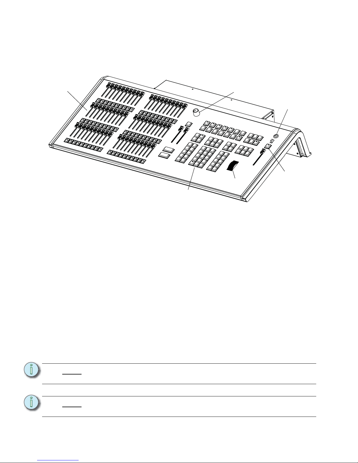
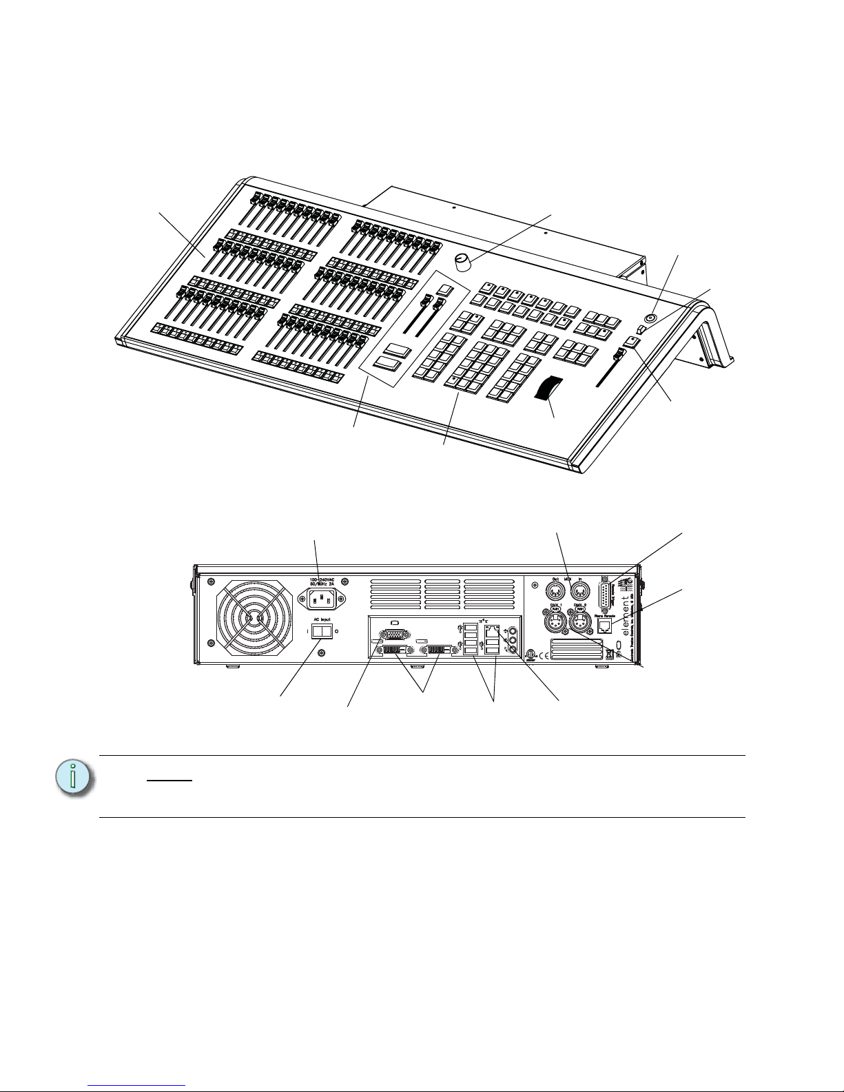
Console Geography
Below is a diagram of Element with references made to specific areas of use. The terms and names
for each area and interface are used throughout this manual.
Note:
Element can support up to 2 monitors, either 2 DVI monitors or 1 VGA and 1 DVI.
For monitor configuration, please See “External Monitor Arrangement” on
page 231.
Power button
USB port
Level
wheel
Control
keypad
Playback
controls
Blackout and
Grandmaster
Faders and
bump buttons
Fader Position
Switch
VGA port
DVI
video
ports
IEC receptacle
MIDI Out and In
Hard power switch
Ethernet
port
DMX ports
1 and 2
USB
ports
Remote
trigger
port
Phone
remote
port
Page 25
2 Element Overview 13
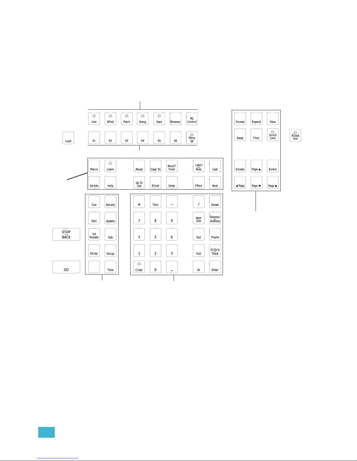
Control Keypad Layout
The control keypad area is divided into several sections including record targets, numeric keypad
with modifiers, display, softkeys, navigation, and special function controls.
Display and navigation keys are used for quick access to common displays, format, paging, and
navigation within displays.
The load button is located above the fader pair and is used to load the specified cue.
ll
Shift
Display
Softkeys
Navigation
Special
function
controls
Record targets
and related
commands
Numeric Keypad and
modifiers
Page 26
14 Element User Manual
Terminology
Power Button
The power button on the front of the desk is used to power up or power down. A separate power
switch, located in the rear panel, can be used to disconnect power from the desk’s internal
components.
USB Ports
One USB port is provided on the front of the console to connect any USB storage device. Additional
USB ports on the rear panel of the console can be used to connect peripherals such as an
alphanumeric keyboard, pointing device, or touchscreen control for external monitors.
Level Wheel
Adjusts intensity for selected channels. It also provides scrolling and zoom functions in various
modes.
IEEE Ethernet 802.3 Ethernet Port
Ethernet port for connection to a network switch, network gateways, and accessory devices.
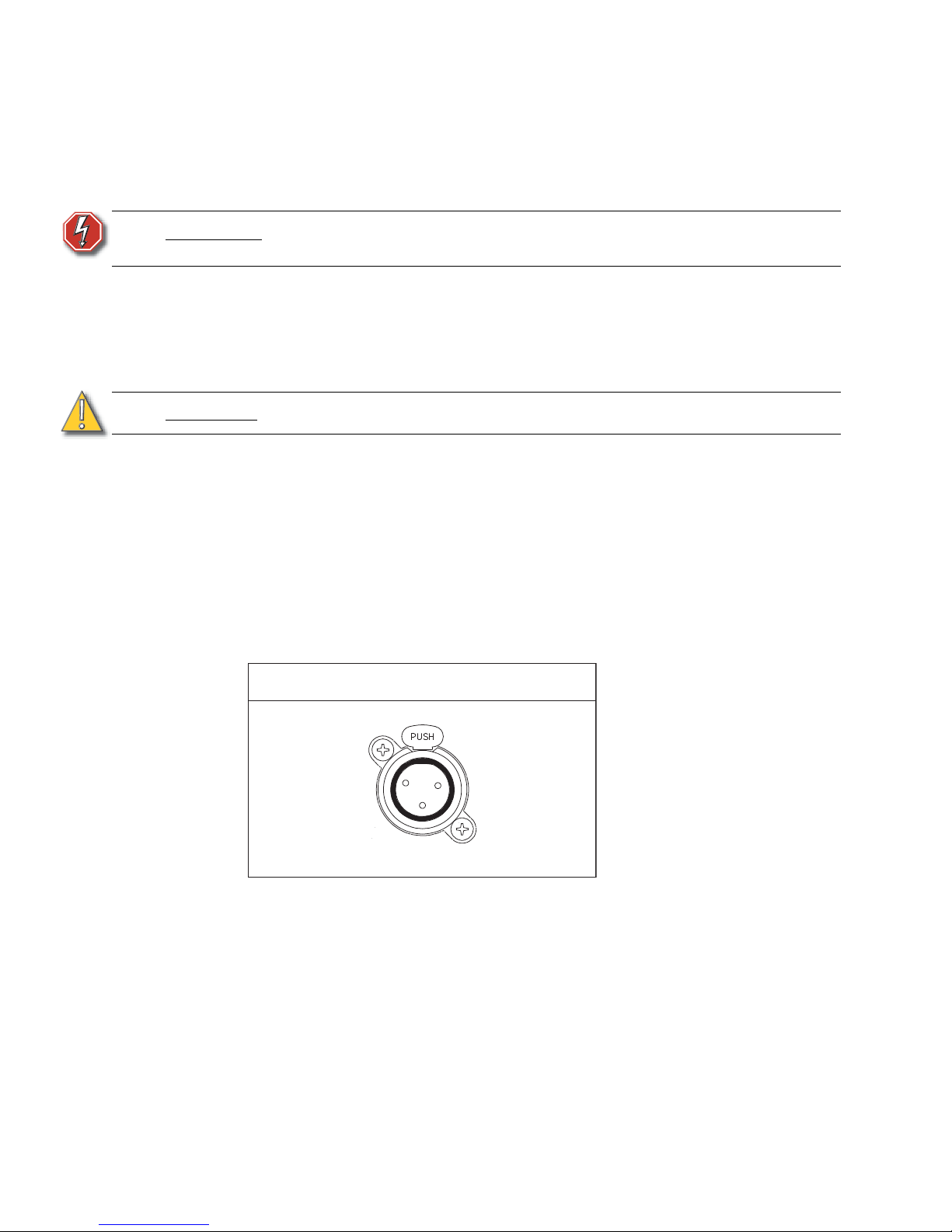
Littlites
®
You may connect a Littlite to the side of your Element.
Dimming Littlites
Attached desk lamps can be dimmed either with the desk lamp control knob on the side of the
console, or from the software.
Desk lamp controls are found in Setup >Desk >Brightness Settings. The {Desk Lamp} slider has
a range of 0% (dimmest) to 100% (brightest). The default setting is 0%. The console will set the
desk lamp to this setting on startup of the application. See “{Brightness Settings}” on page 43.
The desk lamps can also be controlled by holding down [Browser] and rolling the level wheel.
WARNING:
Before servicing Element, you must switch off the power on the rear panel
and disconnect the power cord completely.
CAUTION:
The USB ports cannot be used for charging devices like cell phones.
Littlite XLR 3-Pin Female Connector
1
2
3
Page 27

2 Element Overview 15
Cleaning Element
Should the exterior of your Element require cleaning, you may gently wipe it with a dampened (not
dripping), non-abrasive paper towel or soft cloth.
If this does not clean the console sufficiently, you may apply some window cleaner (containing
ammonia is fine) to the cloth and repeat the process until clean.
Outputting DMX
In order to output levels from Element, you can either use the DMX ports on the back of the console,
or to output over a network, you may connect a Net3 gateway or Net2 node. If your devices receive
Net3 or ETCNet2 directly, no gateway or node is required.
Element has two DMX ports. To output, connect one 5 pin XLR cable per port. The first port will
default to outputting the first universe of DMX, addresses 1-512, and the second port to the second
universe, outputting addresses 513-1024. See Local DMX Outputs, page 243 for information on
reconfiguring the DMX ports.
Nodes and gateways will function with Element out of the box without previous configuration.
However if custom configuration is required, you will need to use either NCE (Network
Configuration Editor) or GCE (Gateway Configuration Editor). GCE is installed on Element by
default and can be accessed in ECU>Settings>Maintenance>Gateway Configuration Editor
(GCE). NCE can be installed on the console or a Windows
®
PC for configuration.
For more information on Net3 gateways or Net2 nodes, see the product literature that accompanied
the hardware or download it from our website at www.etcconnect.com.
Page 28

16 Element User Manual
Console Capacities
Output Parameters
• 1,024 Outputs (DMX channels)
Channel Counts
• 250 or 500 Channels (any number from 1 to 99,999)
Cues and Cue List
• Up to 10,000 cues
• 1 Active Playback
• 1 Cue List
Record Targets
• 1,000 Groups
• 1,000 x 4 Palettes (Intensity, Focus, Color and Beam)
• 1,000 Curves
• 1,000 Effects
• 1,000 Macros
Faders
• 1 Grandmaster with Blackout
• 1 Master Playback, with Go and Stop/Back
• 40 or 60 Faders with bump buttons
• a maximum of 300 configurable submasters
• 120 channel faders
Page 29

3 System Basics 17
Chapter 3
System Basics
This chapter will discuss using the basic Element displays. For more display information, see
Display Conventions, page 245.
This chapter contains the following sections:
• The Central Information Area (CIA) . . . . . . . . . . . . . . . . . . . .18
• Using Softkeys. . . . . . . . . . . . . . . . . . . . . . . . . . . . . . . . . . . . .19
• Using the Browser . . . . . . . . . . . . . . . . . . . . . . . . . . . . . . . . . .19
• Display Control and Navigation . . . . . . . . . . . . . . . . . . . . . . .21
• Using [Format] . . . . . . . . . . . . . . . . . . . . . . . . . . . . . . . . . . . . .24
Page 30
18 Element User Manual
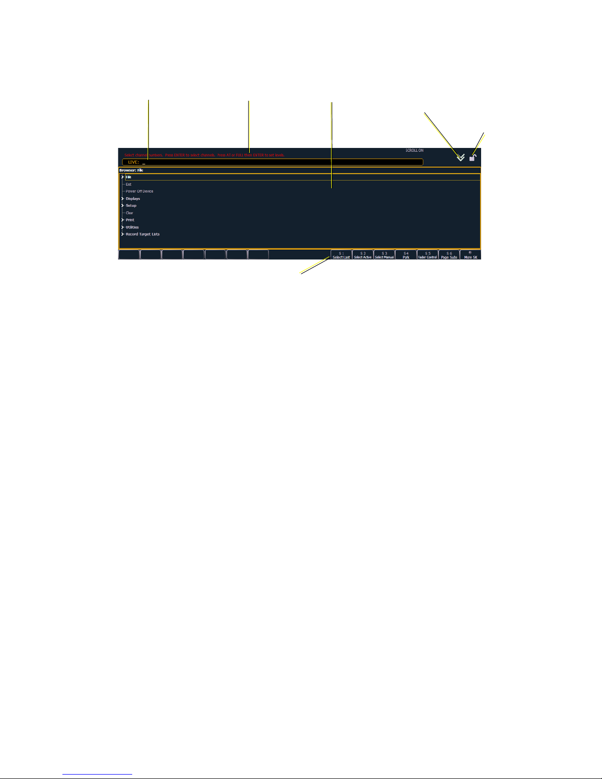
The Central Information Area (CIA)
The Central Information Area (CIA) is displayed on the lower portion of the screen.
Browser
The browser is the interface for numerous functions including saving a show, opening a show,
changing settings, viewing record target lists, opening displays and many other functions. Press
[Browser] to display.
Collapse/Expand the CIA
It is possible to collapse the CIA from view. You can collapse the CIA by pressing [Browser] or by
clicking the double arrow icon on the right side above the CIA. The CIA will collapse from view,
exposing a larger viewing area of whatever display is visible above the CIA.
To expand the CIA into view again, press [Browser] or click the double arrow at the bottom of the
screen. The CIA will reopen.
Lock the CIA
You can lock the CIA in place to prevent it from being collapsed.
To lock the CIA, click on the lock icon above the browser. The double arrow above the CIA will
disappear and the lock will “lock” the CIA to hold it in place.
To unlock the CIA, click the lock again and the double arrows will reappear.
Command Line Prompt
Directly above the command line, you will see red text that will prompt you for an action. The
prompts will change between different displays and actions, and are useful information to aid you in
programming.
Locking the Facepanel
It is possible to lock out the facepanel, which prevents any actions from the command line or CIA.
To lock out the facepanel, press [Shift] & [Escape]. To unlock the facepanel, press [Shift] &
[Escape] again.
Browser Double arrows
CIA show/hide
CIA lock
(shown
unlocked)
Command Line Prompt
Softkeys
Command Line
Page 31

3 System Basics 19
Using Softkeys
Some of the features and displays in Element are accessible from the softkeys, which are located
in the bottom right area of the CIA. Those softkeys correspond to buttons [S1] - [S6] and [More
SK].
Pressing the [Browser] button accesses the following softkeys:
• Effect Status
•Mirror
• Show Control
•Curves
•Magic Sheet
Context Sensitive Softkeys
Softkeys are context sensitive and will change depending on the active display, the current
command line, the active record target, and so on.
Changing Softkey Pages
When there are more relative softkeys than the six available buttons, the LED in the [More SK]
button will light. Press [More SK] to view the additional softkeys.
Using the Browser
To use the browser, you must first draw focus to it by pressing the [Browser] key. If the browser is
not visible, double pressing [Browser] will always bring up the browser.
When focus is on the browser, the window border highlights in gold. The scroll lock LED illuminates
red and the paging keys will now control selection in the browser.
• Use the page arrow keys to move the selection bar up and down the list. You can also use the
level wheel to scroll through the list.
• When the bar highlights the desired menu, press [Page
] to open the menu.
• Continue pressing [Page
] to open submenus.
• Scroll to the item you wish to open using [Page
] or [Page ] and then press [Select]. You
may also click the item you wish to open and then press [Select]. You can also use the level
wheel to scroll in the browser.
• If you wish to close a submenu scroll to that item and press [Page
].
• To draw focus to the browser at any time, press the [Browser] key.
• Additional presses of [Browser] will minimize or restore the CIA.
Menu arrows
Opened menu
Sub menus
Scroll bar
Selection bar
Page 32

20 Element User Manual
Clear Functions
You can access the various clear options from the browser by selecting {Clear} from the main
browser menu. The clear functions window will open in the CIA.
From this menu you can select one of the available clear options by clicking on the desired button
in the CIA. Element will ask you for a confirmation before performing the selected clear. For {Clear
Targets}, Element will allow you to choose which record targets you want to clear.
From the {Clear Targets} screen you can select which record targets you wish to clear. The buttons
at the center of the CIA represent all of the record targets that you can choose to clear. By default
all components are selected (gray) and will be cleared. To withhold any targets from being cleared,
simply deselect them in the CIA by clicking the respective button.
To reselect all targets, click the {Reset} button and all buttons will return to gray (selected). To stop
the process, click the {Cancel} button.
When you have selected or deselected all of the record targets you require, click {OK}.
After clearing, the CIA will return to the browser. If you want to perform additional clear functions,
you must select {Clear} from the browser again.
To exit the clear functions screen without clearing, press the [Browser] key at any time or select a
clear button and then select {Cancel} from the confirmation screen.
Reset System vs Clear Show
Using {Reset System} will open a new show file and reset the Setup options to their defaults. Using
{Clear Show} will only open a new show file.
Reset Patch vs Clear Patch
Using {Reset Patch} will clear your patch and set it to a 1-to-1 patch. Using {Clear Patch} will only
clear out the patch.
Page 33

3 System Basics 21
Display Control and Navigation
Opening and Closing Displays
Displays can be opened and closed in different ways, depending on the display. Many displays are
accessible from Element’s keypad, while other displays are accessible from the browser and
softkeys. List views of record targets can be quickly accessed by double pressing the record target
button, such as [Sub] [Sub] will display the submaster list.
From the hardkeys
Several displays are opened directly from buttons on Element’s keypad. Those displays are [Live],
[Blind], [Patch], [Setup], [Park], [Browser], and [ML Control]. You can open list views of any
record target by double-pressing the key for the desired record target
From the browser
Open and navigate the browser as described in Using the Browser, page 19. When you open a new
display (such as the group list), it will open on the primary display. If the display does not open to a
monitor (such as setup or the browser) it will open in the CIA. Some displays are available from the
softkeys when the [Browser] button is pressed.
Again, any time you wish to return to the browser, simply press [Browser].
Closing Displays
To close any display:
• Press the [Browser] key again to open a different display.
• Press [Escape] to close the active display. The screen will return to live or blind.
• Press [Live] or [Blind] to replace the display with the live/blind view.
To close a display in the CIA, press the [Browser] key and the browser will reappear.
Swap Displays
When using two monitors, you can swap displays between monitors by pressing the [Swap] key.
Press it again to return to the original configuration.
Page 34

22 Element User Manual
Scrolling within a Display
By default the page keys will advance/retreat a display by one page per press. However, to scroll
through displays you may press the [Scroll Lock] key on the keypad. The LED on the button
illuminates red when in scroll lock mode.
Scroll lock is a toggle state. When scroll lock is first pressed:
• [Page
] - scrolls table, spreadsheet and channel views down,
• [Page
] - scrolls table, spreadsheet and channel views up,
• [Page
] - scrolls table and spreadsheet views right,
• [Page
] - scrolls table and spreadsheet views left.
Expanding Displays
[Expand] allows a display to be viewed across multiple monitors.
To expand a display, such as live or patch, press [Expand]. To collapse an expanded view, press
[Expand] again.
[Data] Key
Pressing and holding [Data] allows you to view the values behind any referenced or marked data.
[Data] exposes the next lower reference level. So if you view a palette reference and press [Data],
the absolute data will be displayed instead.
[Data] can also be used to change the address views in patch. See “Using Output Address vs Port/
Offset” on page 50.
[Time] Key
When the [Time] button is pressed on a terminated command line, the selected cue is always
displayed for time modification.
[Label] Key
Element allows for labeling of cues, channels, submasters, and more. Below are some examples of
labeling syntax:
• [Cue] [6] [Label] <name> [Enter]
• [Group] [3] [Label] <name> [Enter]
• [Sub] [8] [Label] <name> [Enter]
If you press the label key for a target already labeled, this posts the current label to the command
line. To clear, press [Label] again. You can [Clear] to backspace one character at a time, or type to
append to the existing label.
[Recall From], [Copy To], {Replace With}, and {Move To}
[Recall From], [Copy To], {Replace With}, and {Move To} may be used to create and edit data.
See “Advanced Manual Control” on page 177.
Note:
You will need a mouse, keyboard, or touchscreen to create labels.
Page 35

3 System Basics 23
Using Flexichannel
Flexichannel (use of the [Flexi] key) allows you to view only channels meeting a certain criteria in
the live/blind display, therefore removing unwanted data from view. Flexichannel has several
available states which include allowing you to view:
• All channels
• All patched channels
• Manual channels
• All show channels (any channels that have data stored in a cue or submaster)
• Active channels (channels with intensity above zero or a move instruction)
• Selected channels
In flexi mode, any selected channels (including the last channel selection) are always included in
the view. Gaps in channel numbers are indicated by a vertical line between the channels where a
gap in numbering occurs.
To change flexi modes in the live/blind display, press [Flexi] to cycle through the views listed above.
When [Flexi] is held down, the softkeys change to represent all of the available flexi states. You can
select the desired flexi view from those keys.
[Next/Last] can be used to select the next or last channel in the current flexi mode.
[Thru] can be used to view only channels in the current flexi mode (except for selected channels
mode) as long as either the first or last channel in the [Thru] range is included in the current flexi
mode. To include channels not in the current flexi mode, [Thru] [Thru] can be used.
View Channels
You may select specific channels to appear in another flexichannel state called “View Channels”.
This state does not exist until you select channels to view. After view channels is activated, it will
appear in the rotation of flexichannel states when [Flexi] is pressed.
To select channels to view:
Step 1: Select channels on the command line (do not press [Enter]).
Step 2: Press and hold [Flexi].
Step 3: Press {View Chans}. The “View Channels” flexi state will be created and the
channels you selected will be visible in it.
The channels you selected will be visible in this flexi state until you select other channels and press
{View Chans} again. At any time, you can access the last channels you defined for this state by
pressing [Flexi] until this state is visible.
To redefine the selected channels in the state, simply follow the steps above again.
Page 36

24 Element User Manual
Using [Format]
Some displays have multiple formats. When the display is first opened, it opens in its default view.
The default view for Live/Blind is table view. Pressing [Format] will toggle between table, summary,
and, if in Blind, spreadsheet views.
Live and Blind share formatting. When you change from one format to another format, you are
always working with the same format until you change it. The exception to this is spreadsheet,
which is only available in blind. If you are working in blind spreadsheet, when you return to live you
will be working with the table or summary view, based on which one you were last using.
Table View
Table view is available in live or blind. If devices other than dimmers are patched, table view
displays the fixture type associated with channels and details about each channel’s category
and
parameter levels.
In live, table view displays all active channel data being output from Element. In blind, it will display
all data for a single record target (cue, palette, submaster).
In the table view, a slight space is provided between fixture types, giving a clear delineation
between them. The name of the fixture type is displayed at the top of the section for that fixture.
Fixture type
Parameter data
Live Table View
Page 37

3 System Basics 25
Summary View
The summary view displays the largest number of channels of any of the formats. Below you can
see channels 1-80 are shown. This format is best used to see large numbers of channels’ intensity
data or parameter category data. Individual non-intensity parameters are not visible in this view.
Zooming Displays
You may zoom the table and summary view to display more or less channels. To do this, press and
hold the [Format] button and scroll the Level Wheel to alter the number of channels visible.
Scrolling the wheel up zooms in. Scrolling the wheel down zooms out. Zooming this display when
it is in 100 channel mode is not supported. A mouse can also be used to control zooming by holding
down the left button while using the scroll wheel.
Channel numbers
Intensity data
F, C, B data Deleted channelUnpatched channel
Page 38

26 Element User Manual
Spreadsheet (Blind Only)
Spreadsheet format is available only in blind mode. It is useful for viewing and editing channel data
and trends for multiple cues, submasters, or palettes at one time. Cues and other record targets are
displayed on the vertical axis and channel data is visible on the horizontal axis. See “Recording and
Editing Cues from Blind” on page 116.
To toggle between viewing just the intensity information and other parameters, press [Shift] &
[Format].
Channel number
Cue numbers
Parameters
Page 39

4 Managing Show Files 27
Chapter 4
Managing Show Files
This chapter explains how to create, open, and save your show files. Each of these operations are
accomplished through the browser area.
This chapter contains the following sections:
• Create a New Show File. . . . . . . . . . . . . . . . . . . . . . . . . . . . . .28
• Open an Existing Show File . . . . . . . . . . . . . . . . . . . . . . . . . .28
• Merging Show Files . . . . . . . . . . . . . . . . . . . . . . . . . . . . . . . . .31
• Printing a Show File. . . . . . . . . . . . . . . . . . . . . . . . . . . . . . . . .33
• Saving the Current Show File . . . . . . . . . . . . . . . . . . . . . . . . .34
• Using Quick Save. . . . . . . . . . . . . . . . . . . . . . . . . . . . . . . . . . .34
• Using Save As . . . . . . . . . . . . . . . . . . . . . . . . . . . . . . . . . . . . .35
• Importing Show Files. . . . . . . . . . . . . . . . . . . . . . . . . . . . . . . .35
• Exporting a Show File . . . . . . . . . . . . . . . . . . . . . . . . . . . . . . .36
• Deleting a File. . . . . . . . . . . . . . . . . . . . . . . . . . . . . . . . . . . . . .36
• File Manager. . . . . . . . . . . . . . . . . . . . . . . . . . . . . . . . . . . . . . .36
Page 40

28 Element User Manual
Create a New Show File
To create a new show file, navigate within the browser to: File> New> and press [Select].
You will be prompted for confirmation that you want to create a new show. Any unsaved show data
will be lost. Press [Select] or click {OK} to confirm or {Cancel} to discontinue the operation.
In Element, a new show file defaults to a 1-to-1 patch. Clicking {Patch 1to1} will deselect the option
and result in a blank patch.
Open an Existing Show File
Names of show files may appear in the browser list in normal text or in bold text. Files in normal
text indicate that there is only one show file stored by that name.
Bold show names indicate that there are several versions of the show file stored under that name,
the bold one being the most recent. To access the most recent show file, simply select the bold
name. You may right arrow [
] from the bold name to expand a list of previous versions beneath it
in the browser. Select the desired show from the expanded list.
To open an existing Element show file, navigate within the browser to: File> Open> and press
[Select].
Element provides you with multiple locations to retrieve an Element show file (.esf) including:
• Show File Archive - This is the default storage location for show files when a show file is
created and saved. Older versions of the show file will be listed under the most current
version. This allows you the ability to open the latest version or an earlier version of a show
file if desired.
• File server - if one is connected. When there is no file server connected, it will not display in
the browser. See “Network Drives” on page 241.
• USB storage device - When a USB device is connected and an Element show file (.esf) is
available on the device, you will notice the USB device’s name and drive letter are displayed
in white text and expandable.
Open the desired location:
• To open a show file from the Show File Archive, navigate within the browser to: File> Open>
Show File Archive and press [Select].
• To open a show file from the file server, navigate within the browser to: File > Open> File
Server> and press [Select].
• To open a show file from a USB device, navigate within the browser to: File> Open> Name
of Drive and press [Select].
Page 41

4 Managing Show Files 29
Select the specific show file
• Navigate within the specified storage location and select the show file you wish to open, press
[Select].
• If the selected show has multiple time stamps and you wish to load an older version, navigate
to the desired revision and press [Select].
This will open the partial show loading screen in the CIA.
From this screen you can select which components of the show file you wish to load. The buttons
at the center of the CIA represent all of the show components that you can choose to load. By
default all components are selected (gray) and will be loaded. To withhold any show components
from loading, simply deselect them in the CIA by clicking the respective button.
To reselect all show components, click the {Reset} button and all buttons will return to gray
(selected). To stop the show load process, click the {Cancel} button.
When you have selected or deselected all of the show components you require, press [Select] or
click {OK}.
Element loads the selected show to the console.
Note:
You will need a mouse, keyboard, or touchscreen to deselect options.
CAUTION:
On a partial show open, if any record targets are not opened, any existing data of
that type will be cleared from the console.To merge show data, merge should be
used. See “Merging Show Files” on page 31.
Page 42

30 Element User Manual
Selective Partial Show Opening
If you select the {Advanced} button in the partial show opening screen, you will have the
opportunity to load partial components from the show file and be able to specify the desired location
of those partial components in the new show file.
For example, you could specify only cues 5-10 and load them as cues 20-25 in the new show. You
could also specify only specific palettes, effects, and so on. To see the complete list of show
components, press the {Advanced} key in the partial show loading screen.
As you specify components, they are added to a table in the CIA. In the table, fields with a dark
background may be edited, fields with a light gray background do not apply to that component. For
each component in the list, you can specify the desired range by clicking in the proper area in the
table and entering numbers from the keypad. The columns in the table are:
• List - The list you are taking data from (such as a cue list).
• List Target - The list you are adding the data to.
• Start - The first in a range of components (such as a range of cues).
• End - The last in a range of components.
• Target - The desired location of the components in the new show file (for ranges, this
will be the location in the new show of the first component in the range, the others will
follow in order).
Partial Patch Opening
You have the option to selectively open partial patch information or fixtures into a show file by
selecting the {Advanced} button in the partial show opening screen.
You can specify the desired range by selecting the proper area in the table and entering numbers
from the keypad. The columns in the table that relate to patch are:
• Start - The first in a range of components.
• End - The last in a range of components.
• Target - The desired location of the components in the new show file (for ranges, this
will be the location in the new show of the first component in the range, the others will
follow in order).
Note:
It is important to remember that on a partial patch open, if any record targets are
not opened, any existing data of that type will be cleared from the console. To
keep that data, merge should be used.
Selected Show Components
Page 43

4 Managing Show Files 31
Merging Show Files
Element supports the merging of .esf show files.
You have the option of merging .esf show files from the Show File Archive, a File Server (if
connected), or a USB device.
To merge a show file, navigate within the Browser to: File> Merge>. Navigate to the desired
storage location and press [Select]. When using merge, Element displays only the available files.
Navigate to the specific file and press [Select].
This will open the merge screen in the CIA. From this screen you can choose which aspects of the
show file you want to merge. By default all aspects are unselected (black). Selected show aspects
will appear in gray.
If you select the {Advanced} button in the merge show loading screen, you will have the
opportunity to load partial components from the show file and be able to specify the desired location
of those partial components in the current show file.
For example, you could specify only cues 5-10 and load them as cues 20-25 in the cue list in the
current show. You could also specify only specific palettes, effects, and so on. To see the complete
list of show components, press the {Advanced} key in the merge show loading screen.
As you specify components, they are added to a table in the CIA. In the table, fields with a dark
background may be edited, fields with a light gray background do not apply to that component. For
each component in the list, you can specify the desired range by pressing the proper area in the
table and entering numbers from the keypad. The columns in the table are:
• List - The list you are taking data from (such as a cue list).
• List Target - The list you are adding the data to.
• Start - The first in a range of components (such as a range of cues).
• End - The last in a range of components.
• Target - The desired location of the components in the new show file (for ranges, this
will be the location in the new show of the first component in the range, the others will
follow in order).
Note:
Merging show files is different from opening show files. When you do a partial
open of show components, untouched record targets are cleared. When you do a
merge, those record targets remain.
Selected Show Components
Page 44

32 Element User Manual
To merge only partial components:
Step 1: From the browser, navigate to the desired show file (see Open the desired location:,
page 28).
Step 2: When the merge show load screen appears, press the {Advanced} button. The
partial components selection screen will appear in the CIA.
Step 3: Select the show components that you wish to merge by pressing on their respective
buttons on the left side of the CIA. The components will appear in the list to the right
as you select them.
Step 4: Press any fields for which you want to enter specific numbers. The field (if editable)
will highlight in gold.
Step 5: Enter the numbers using the keypad to specify the desired cues/groups/effects and so
on.
Step 6: Press {OK} to load the components to the current show.
Partial Patch Merging
You have the option to selectively merge partial patch information into a show file by selecting the
{Advanced} button in the partial show merge screen.
You can specify the desired range by selecting the proper area in the table and entering numbers
from the keypad. The columns in the table that relate to patch are:
• Start - The first in a range of components.
• End - The last in a range of components.
• Target - The desired location of the components in the new show file (for ranges, this
will be the location in the new show of the first component in the range, the others will
follow in order).
Page 45

4 Managing Show Files 33
Printing a Show File
Element provides you with the ability to save a show file or aspects from a show file to a PDF file for
printing. Element has three locations to save the PDF files including the Show File Archive, the File
Server (if connected), or a USB device (if connected). Saving the PDF file to a USB storage device,
allows you to then print the PDF from a personal computer. Printing directly from Element is not
supported. To save a PDF of an Element show file, navigate within the browser to: File> Print> and
press [Select].
You can select the page orientation and paper type in Setup >Desk >PDF File Settings.
This will open the printing screen in the CIA. From this screen you can choose which aspects of the
show file you want to save to PDF. By default all aspects are selected (gray) and will be saved. To
withhold any show aspects from printing, simply deselect them in the CIA by clicking the respective
button. Deselected show aspects will appear in black.
Three buttons that will impact the overall PDF are {Tracked Levels}, {Color Printout}, and
{Summary View}.
• {Tracked Levels} - will display all tracked levels when selected.
• {Color Printout} - will display the values in color to match the way they are displayed on the
console when selected. When deselected, the values will appear in grayscale.
• {Summary View} - will display the same information as the summary view display. See
“Summary View” on page 25.
To reselect all show aspects, press the {Reset} touchbutton and all buttons will return to gray
(selected). To stop the show file from being saved to a PDF and return to the browser, press the
{Cancel} button. When you have selected/deselected all of the show aspects you require, press
the {Ok} button to create the PDF file.
Page 46

34 Element User Manual
You can also choose to print specific portions of show aspects. To select this information, press the
{Advanced} button. The touchbuttons at the center of the CIA will again represent all of the show
aspects that you can choose. By default all aspects will be deselected (black).
As you select aspects, they will be added to the table in the CIA. For each component in the list, you
can specify the desired range by pressing the proper area in the table and entering numbers from
the keypad. The columns in the table are:
• List - The list you are taking data from (such as a cue list).
• Start - The first in a range of components (such as a range of cues).
• End - The last in a range of components.
To deselect all show aspects, press the {Reset} touchbutton and all buttons will return to black
(deselected).
To return to the main print screen, press the {Advanced} button. To stop the show file from being
saved to a PDF file and return to the browser, press the {Cancel} button. If you are ready to save
the file, press the {Ok} button. You will be prompted to name the file.
The PDF will have the show name, date and time it was created, and date and times for when the
show file was last saved. It also gives the Element software version information. If multiple aspects
were selected to save to the file, there will be hyperlinks at the top of the PDF so you can quickly
jump to a section.
Saving the Current Show File
To save the current show data, navigate within the browser to: File> Save> and press [Select].
The Show File Archive is the default storage location for show files when they are saved. The new
time stamp located beneath the show file name on the CIA indicates that the show file has been
saved.
All previous saves are stored in the Show File Archive with the time stamp following the file name.
Using Quick Save
To save the current show data to the hard drive without having to navigate to the browser, hold
down [Shift] & [Update].
Note:
When saving a show file for the first time, Element will provide the name “Show
File” and will attach a time/date stamp to the name. To change the name, use a
mouse and the on-screen keyboard, or an attached USB keyboard.
Selected Show Component
Page 47

4 Managing Show Files 35
Using Save As
To save an existing Element show file to a different location or with a different name, navigate within
the browser to: File> Save As> and press [Select].
Element provides you with three locations to save an Element show file (.esf) including the Show
File Archive, the File Server (if connected) or a USB device (if connected).
Navigate to the desired storage location and press [Select]. When using “Save As” to save the
show file to a specific location, the alphanumeric keypad will display on the CIA. Name the show file
and press [Enter]. The show file will be saved in the specified location with the show file name you
entered with a time stamp suffix.
Pressing [Label] or [Delete] on the console, or DELETE on an alphanumeric keyboard will remove
the default show label when doing a Save As.
Importing Show Files
Element supports the import of standard USITT ASCII, and Lightwright® text files.
You have the option of importing standard USITT ASCII (.asc) or Lightwright data (.txt or .asc) from
the Show File Archive, a File Server (if connected), or a USB device.
To import a show file, navigate within the Browser to: File> Import> (Type of file to import) and
press [Select]. If you are importing an USITT ASCII file, you will have two options, Import as Library
Fixtures or Import As Custom Fixtures. Import as Library Fixtures will allow Element to try to match
the fixtures in the file with fixtures in the Element library. Import as Custom Fixtures will bring the
fixtures in as they are in the file. It is recommended to use Import as Custom Fixtures.
Navigate to the desired storage location and press [Select]. When using import, Element displays
only the available files. Navigate to the specific file and press [Select].
Note:
Element supports ASCII show file import from a number of other control consoles,
including the Congo, Obsession, Expression, Emphasis, and Congo product lines,
as well as the Strand 300 Series. Please note that all show files must be saved in
an ASCII format prior to importing them into Element.
CAUTION:
The way data is stored and used is often different between different desks.
Imported data may not playback exactly the same between desks. Not all data
(such as effects and macros) may be imported. This varies by product.
Page 48

36 Element User Manual
Exporting a Show File
Export your Element show file to a standard USITT ASCII, .csv, Focus Track, or Fast Focus Pro
show file using the export feature.
To export your Element show file in ASCII format, navigate within the browser to: File> Export>
USITT ASCII and press [Select]
You have the option of exporting your show file in ASCII format to the Show File Archive, to a File
Server (if connected), or to a USB device.
Navigate to the desired storage location and press [Select]. The alphanumeric keypad will display
on the CIA. Name the show file and press [Enter]. The file will be saved in the specified location
with the file name you entered with a “.asc” file extension.
You can export Element show files as a .csv format by navigating within the browser to: File>
Export> CSV and select the location for the export, the Show File Archive, a File Server (if
connected), or to a USB device.
Files can also be exported as in a Focus Track or Fast Focus Pro format by going to File> Export>
Fast Focus Pro or Focus Track and select the location for the export, the Show File Archive, a File
Server (if connected), or to a USB device.
Deleting a File
Element provides you with the ability to delete show files from the Show File Archive and the File
Server from within the browser.
To Delete a Show File
Navigate within the browser to: File> Open and press [Select]. Navigate to the desired show file
and press [Delete]. Press [Enter] to confirm or any other key to abort the deletion process.
To Delete a Folder
The folder must first be empty.
Navigate within the Browser to: File> Open and press [Select]. Navigate to the desired folder and
press [Delete]. Press [Enter] to confirm or any other key to abort the deletion process.
File Manager
Element has a file manager, which provides a way to manage show files. See “File Manager” on
page 240.
Page 49

5 Setup 37
Chapter 5
Setup
This chapter discusses Element’s system settings that you can change to meet your preferences.
This chapter contains the following sections:
• Opening Setup . . . . . . . . . . . . . . . . . . . . . . . . . . . . . . . . . . . . .38
• Show . . . . . . . . . . . . . . . . . . . . . . . . . . . . . . . . . . . . . . . . . . . . .38
• Desk . . . . . . . . . . . . . . . . . . . . . . . . . . . . . . . . . . . . . . . . . . . . .41
Page 50

38 Element User Manual
Opening Setup
There are two ways to open the setup screen. You can either press [Setup] or press [Browser] and
scroll down to {Setup}.
The CIA will display the setup screen and the softkeys will change. Element will default to
displaying show settings, however if you change the view, Element will remember the view you
were in when you return to setup.
The setup displays are:
•Show
•Desk
Show
When you select the {Show} softkey, the CIA will display the following buttons:
• Show Settings
• Cue Settings
• Show Control
Show Settings
Click {Show Settings} to enter this category.
Seven fields will be available to you: {Num of Channels}, {Dim. Dbl. Offset}, {Allow HS Fades},
{Fader Mode}, {Mark Time}, {Startup Macro}, and {Disconnect Macro}.
{Num of Channels}
You may use this field to set the number of channels in your Element up to 10,000. However, you
are limited to only patch up to the number of channels that are available from your system, either
250 or 500 depending on the channel count for your Element. Enter the number of channels for
your system using the keypad. This is useful for controlling paging. This entry must be confirmed
with the [Enter] key.
{Dim. Dbl. Offset}
This allows you to set the address offset for dimmer doubling. The default for this is 20000, to match
the Net2 standard offset, including Sensor dimming software. For dimmer doubling over Local
DMX, this value should be set to 256.
{Allow HS Fades}
Hue and saturation (HS) color data normally fades in native space. Enabling {Allow HS Fades} will
make HS data fade in HS space.
{Fader Mode}
This field allows you to set the fader mode for the cue list. Options toggle between Proportional
Master, Intensity Master, and Manual Master. For more information on Proportional and Intensity
Masters, See “Proportional vs. Intensity Master” on page 93.For information on Manual Master,
See “Manual Master Option” on page 134.
Note:
To select buttons in the show and desk displays, you can either use a mouse or
the arrow keys on Element along with the {Properties} softkey. {Properties} will
allow you to scroll through the fields and pressing [Select] will choose a field.
Pressing [Select] again will toggle options, such as ‘Enabled’ and ‘Disabled”.
Some fields require data from the keypad and then [Enter]. Selecting
{Properties} again will return the scroll ability to the buttons on the left of the CIA.
Page 51

5 Setup 39
{Mark Time}
This field allows you to set the time that non-intensity mark instructions will use. When {Mark Time}
is disabled, which is the default, mark instructions will use cue timing.
{Startup Macro}
This field allows you to set up a startup macro that will trigger after the console initialization has
completed.
{Disconnect Macro}
This field can be use for disconnect macros or shutdown macros.
• Disconnect Macro - allows you to set up a disconnect macro that will trigger when the primary
disconnects from its backup, or when a backup disconnects from the primary.
• Shutdown Macro - allows you to set up a disconnect macro that will trigger at power off, not
when exiting the application.
{Cue Settings}
Click {Cue Settings} to enter this category.
You will be able to set the cue default times for intensity up and down.
{Show Control}
For more information on using show control with your system, see the Eos Family Show Control
User Guide, which is available for download at www.etcconnect.com
.
{SMPTE Time Code Rx}
This touchbutton is used to control whether your console can receive SMPTE time code. Choosing
“Disabled” will disable all time code lists that have a SMPTE source. The default for this setting is
“Enabled”.
{MIDI Time Code Rx}
As above, but for MIDI Time Code instead of SMPTE. The default for this setting is “Enabled”.
{Resync Frames}
This touchbutton allows you to configure how many frames need to be synced before timecode
starts running. Frames can be from 1-30. Default is 2 frames.
{MSC Receive}
This touchbutton toggles the setting for receiving MIDI Show Control from an external source
between “Enabled” and “Disabled”. The default setting is “Disabled”.
{MSC Receive Channel}
Also known as a “Device ID” this setting configures the MIDI channel for the console to receive
MIDI Show Control information. Only MSC data with the same device ID will be received. A device
ID can be from 0-126, or if set to 127, Eos Ti, Gio, Ion, or Element will receive MSC data from all IDs
(All Call). Eos cannot be set as an All Call receiver. For example:
• {MSC Receive Channel} [5] [0] [Enter]
Page 52

40 Element User Manual
{ACN - MIDI Rx ID(s)}
This setting allows you to specify the MIDI Show Control data that your console will receive when
transmitted over the Architecture for Control Network (ACN). When set, the console will respond to
MSC data from any gateway that has its “ACN MIDI Rx ID” set to the same number. ACN MIDI Rx
ID can be from 1-32. ID ranges may be used. When using the local MIDI ports on Eos Ti, Gio, Ion,
or Element, this setting needs to match the MIDI Rx Group ID in the ECU>{Settings}>{Local I/
O}>Show Control Gateway>Group IDs.For example:
• {ACN MIDI Rx ID} [2] [5] [Enter]
• {ACN MIDI Rx ID} [1] [Thru] [1][0] [Enter]
{MSC Transmit}
This setting, when enabled, allows the console to send MSC messages for actions taken on the
console, such as cue actions, macros firing, and submaster bumps. The default setting is
“Disabled”.
{MSC Transmit Channel}
Also know as “Device ID” this setting allows you to establish the device ID with which your console
will transmit MIDI Show Control information. A device ID can be from 0-126, or if set to 127, Eos,
Eos Ti, Gio, Ion, or Element will transmit MSC data to all IDs (All Call). For example:
• {MSC Transmit Channel} [5] [0] [Enter]
{ACN - MIDI Tx ID}
This setting allows you to specify the ID number of MIDI Show Control data that the console
transmits over an Architecture for Control Network (ACN). When set, the console will transmit MSC
data to any gateway that has its “ACN MIDI Tx ID” set to the same number. ACN MIDI Tx ID can be
from 1-32. When using the local MIDI ports on Gio, Ion, or Element, this setting needs to match the
MIDI Tx Group ID in the ECU>{Settings}>{Local I/O}>Show Control Gateway>Group IDs. For
example:
• {ACN MIDI Tx ID} [2][5] [Enter]
{String MIDI TX}
When enabled, this setting will cause the console to send serial strings instead of a MIDI Show
Control message when certain actions happen at the console.
{MIDI Cue List}
MIDI Cue List specifies the cue list that the console will use to send MSC data. If left blank and MSC
Tx is enabled, all cue lists will generate MSC events. Otherwise, only the particular list (or lists)
selected will fire MSC events.
{Analog Inputs}
This is a master setting for receiving analog inputs from a Net3 I/O Gateway or the local analog
ports on a Gio, Ion, or Element. When disabled it will turn off all analog input for all event lists.
Default is “Enabled”.
{Relay Outputs}
This is a master setting for triggering external relays from a Net3 I/O Gateway or the local ports on
a Gio, Ion, or Element. When disabled it will turn off all external relays for all event lists. The default
is “Enabled”.
{String RX}
This setting will enable receiving strings on all Serial RX formats.
Page 53

5 Setup 41
{String RX Group IDs}
This button is for setting up which Serial Port Group ID (from I/O Gateway settings in GCE) the
console will listen to. This only affects serial traffic from I/O gateways, not network UDP messages
or ACN strings. Group IDs are from 1-32. Remember group IDs relate to the number set in the
gateway. It can be set to listen to multiple group IDs by using [Thru] and [+].
{String RX Port}
This setting specifies the UDP port that the console will listen to for receiving strings.
{String TX}
This settings will enable sending strings on all Serial TX formats.
{String TX Group IDs}
This button is for setting up which Serial Port Group ID (from I/O Gateway settings in GCE) the
console will send to. This only affects serial traffic to I/O gateways, not network UDP messages or
ACN strings.Group IDs are from 1-32. Remember group IDs relate to the number set in the
gateway. It can be set to send to multiple group IDs by using [Thru] and [+].
{String TX Port}
Setting for the UDP destination port that the console will send strings.
{String TX IP Address}
Sets the destination IP address that the console will send strings.
Desk
When you select the {Desk} softkey, the CIA will display the following buttons:
• Record Defaults
• Manual Control
• Face Panel
• Face Panel Keypad
• Displays
• PDF File Settings
• Brightness Settings
•RFR Settings
• Trackball Settings
{Record Defaults}
This screen enables you to change general record defaults.
Auto Playback
When enabled, this feature automatically plays back cues as they are stored and releases manual
control. This field is a toggle state between “Enabled” and “Disabled”. When auto playback is
“Disabled”, all manual levels are maintained and cues must be loaded and executed on the split
fader. The default is “Enabled”.
Track
This field allows you to switch between tracking and cue only modes (see Tracking vs. Cue Only,
page 224). The default is “Tracking”.
Page 54

42 Element User Manual
Record Confirm
This setting allows you to enable or disable the confirm action when storing over a previously
recorded target. The default is “Enabled”.
Delete Confirm
This field allows you to enable or disable a required confirmation before any delete command is
executed. The default is “Enabled”.
{Manual Control}
This desk setting button gives you access to Element’s manual control settings.
Manual Time
In this section you may change the default times for manual changes to occur in live. Times can be
set for Intensity Up and Intensity Down.
Manual Control
This section allows you to specify the values for certain buttons and settings used in manual
control. To change any value, click the appropriate button in the CIA and use the keypad to enter a
new value.
Preserve Blind Cue - This enables the console to display the last selected cue in blind
when you return to blind. The default is disabled.
Level - This sets the default for Level (which is accessed in Element by double pressing
[At]). Any value between 0-100 may be entered. The default is 100.
Plus% - This sets the level for the +% (which is accessed in Element by pressing [Shift] &
[+]), which will increase the selected channel by the set percentage. Any value between 0-
100 may be entered. The default is 10%.
Minus% - This sets the level for -% (which is accessed by pressing [Shift] & [-]), which will
decrease the selected channel by the set percentage. Any value between 0-100 may be
entered. The default is 10%.
Rem Dim Level - This allows you to set the level for all Remainder Dim commands. The
default is 0.
Default Times
In this section you may change the default times for sneak commands, back time, and go to cue
time. The default for these is 5 seconds, except for back time, which uses a default of 1 second.
{Face Panel}
In this section you may change the sounds settings as well as adjusting the increment and
acceleration effect of the level wheel.
{Face Panel Keypad}
Auto Repeat
This setting allows you to adjust the auto repeat settings (delay and speed) for the facepanel
keypad.
Blackout
You can disable the [Blackout] hardkey here. By default, blackout is “Enabled”.
Grandmaster
You can disable the Grandmaster. By default the Grandmaster is “Enabled”.
Spacebar [Go]
You can enable the spacebar on an external keyboard as the hotkey for [Go]. By default, it is
“Disabled”.
Page 55

5 Setup 43
Hide Mouse
With hide mouse enabled, if the mouse is left idle for 10 seconds, the cursor will go away. Once the
mouse is used again, the cursor will return. By default, this is “Disabled”.
{Displays}
This desk setting button gives you access to the Element display settings.
High Contrast Display
This button toggles the setting between “Enabled” and “Disabled”. When enabled, high-contrast
brightens the magenta used to show tracked values.
The default setting for this is “Disabled”.
Show Reference Label
This button toggles the setting between “Enabled” and “Disabled”. When enabled, referenced
record targets (such as palettes) with labels will have their labels displayed in the live/blind display
rather than their target type and number. [Shift] & [Label] can be used to temporally toggle
between views.
The default setting for this is “Disabled”.
Group Chans By 5
You can turn off/on the grouping of channels in groups of 5 in the live summary view from this field.
The default for this setting is “Enabled.
100 Channel Display
This setting can be used to display 100 channels at a time in the live summary view. The default for
this setting is “Disabled.”
Cmd Line on PSD
This setting can be used to display an optional command line on the Playback Status Display. The
default for this setting is “Disabled”.
PSD Time Countdown
In the Playback Status Display (PSD), holding down [Time], while a cue is fading, will display the
cue category times counting down in the cue list display area. The default action is to show the total
time not the countdown. When the {PSD Time Countdown} is enabled, the cue category times will
countdown as a cue is fading. To see the total time, hold down the [Time] key. {PSD Time
Countdown} is “disabled” by default.
{PDF File Settings}
This screen allows you to select the orientation and paper type for PDF files.
{Brightness Settings}
This screen allows you to adjust the brightness of attached desk lamps. The {Desk Lamp} fader
has a range of 0% (dimmest level) to 100% (brightest level).
{RFR Settings}
This screen is for allowing Net3 RFR, iRFR, and aRFR connections. The default setting is
“Enabled”. For more information see RFR, page 244 and Remote Focus Remote (RFR), page 258.
Page 56

44 Element User Manual
{Trackball Settings}
This screen allows you to make adjustments to a trackball.
{Trackball Tick Freq.}
This fader adjusts the trackball tick frequency. The default is 200 ticks.
{Trackball Acc. Fctr}
This fader adjusts the trackball acceleration factor. The default is 800 zip.
{Swap Pan/Tilt}
This touchbutton swaps the directions for Pan and Tilt on a trackball. The default for Pan and Tilt is
X and Y, respectively. When this button is enabled, Pan and Tilt will be Y and X.
{Reverse Pan}
This touchbutton reverses the direction of Pan.
{Reverse Tilt}
This touchbutton reverses the direction of Tilt.
{Reset}
This button resets all five trackball settings back to their default.
Page 57

6 Patch 45
Chapter 6
Patch
The Patch is used to associate a channel with an address. Once a channel is patched to an
address, and the output is connected to a device (for example a dimmer, moving light, or
accessory), the channel will then control that device.
This chapter contains the following sections:
• About Patch . . . . . . . . . . . . . . . . . . . . . . . . . . . . . . . . . . . . . . .46
• Displays . . . . . . . . . . . . . . . . . . . . . . . . . . . . . . . . . . . . . . . . . .47
• Patching Conventional Fixtures. . . . . . . . . . . . . . . . . . . . . . .48
• Patching Scrollers . . . . . . . . . . . . . . . . . . . . . . . . . . . . . . . . . .52
• Using the Scroller Editor. . . . . . . . . . . . . . . . . . . . . . . . . . . . .53
• Calibrating a Scroller. . . . . . . . . . . . . . . . . . . . . . . . . . . . . . . .58
• Patching Moving Lights, LEDs, and Accessories. . . . . . . . .59
• Display Pages in Patch . . . . . . . . . . . . . . . . . . . . . . . . . . . . . .61
• Using Device List. . . . . . . . . . . . . . . . . . . . . . . . . . . . . . . . . . .66
• Dimmer Doubling. . . . . . . . . . . . . . . . . . . . . . . . . . . . . . . . . . .72
• Moving and Copying Channels . . . . . . . . . . . . . . . . . . . . . . .72
• Swapping Channels. . . . . . . . . . . . . . . . . . . . . . . . . . . . . . . . .73
• Unpatch a Channel . . . . . . . . . . . . . . . . . . . . . . . . . . . . . . . . .73
• Deleting Channels . . . . . . . . . . . . . . . . . . . . . . . . . . . . . . . . . .73
• Clearing the Patch . . . . . . . . . . . . . . . . . . . . . . . . . . . . . . . . . .74
• Update Library . . . . . . . . . . . . . . . . . . . . . . . . . . . . . . . . . . . . .74
• Fixture Editor . . . . . . . . . . . . . . . . . . . . . . . . . . . . . . . . . . . . . .75
Page 58

46 Element User Manual
About Patch
Element treats fixtures and channels as one and the same, meaning each fixture is assigned a
single control channel number. Individual parameters of that fixture, such as intensity, pan, tilt,
zoom, or iris are also associated with that same channel number but as additional lines of channel
information.
You are required to enter only the simplest data to patch a device and begin programming your
show, such as the channel number, the device type (if needed), and address. When you provide
more information in the patch, you will have more detailed control and improved function during
operation.
One or more devices may be patched to a single channel. For example you may want to patch a
group of dimmers to the same channel. In addition you may patch multiple devices to the same
channel for building a compound or accessorized fixtures. For example a Source Four
®
with a color
scroller and a gobo changer may be patched to a single channel. This is referred to as a compound
channel.
When you open a new show file, Element creates a 1-to-1 patch. This means that the patch will
automatically have channel 1 patched to address 1, channel 2 to address 2, and so on up to the
maximum channel count of your console.
Depending on your situation, you may need to create a custom patch, which associates certain
addresses with certain channels.
Note:
You can open or merge patch data from other show files, see Partial Patch
Opening, page 30 and Partial Patch Merging, page 32 for more information.
Selected to create a 1-to-1 Patch Will not create a 1-to-1 Patch
Page 59

6 Patch 47
Displays
To begin patching your show, you must first open the patch display. To open the patch display, press
press [Displays] and then {Patch}.
The patch display will open on an available external monitor and the CIA will display patch controls.
If there are no monitors attached, patch will open on one of the on-board monitors.
From within the patch display, you can open the Device List to use RDM to patch any RDM
compatible devices. For more information about Device List, see Using Device List, page 66.
The patch screen will display the following information if available:
• Channel - the patched channel number. In patch by address mode, channel will appear blank
if not currently patched.
• Address - the patched output address. In patch by channel mode, address will appear blank
if not currently patched. Pressing [Data] toggles the display from showing address as patched
by the user, output address, and the port/offset. See “Using Output Address vs Port/Offset” on
page 50.
• Type - device or dimmer type that is patched.
• Label - displays the assigned label of the channel or address. See Labeling, page 48.
• Interface - displays which interfaces will be used for the device. See {Interface} in {Patch}
Display and Settings, page 61.
• Output - displays the current live intensity level. Value is displayed as 0-255, with 255 being
full.
Status in the Patch Display
Status flags will display on the far left of the patch display to advise you when a channel or address
requires your attention.
A red “!” or yellow “?” will display when there is a warning or error from an RDM, CEM+, CEM3, or
ACN device. See “Errors and Warnings” on page 70.
Page 60

48 Element User Manual
Patching Conventional Fixtures
For patching fixtures, there are two different patch modes: patch by channel and patch by address.
Element defaults to patch by channel mode. Pressing [Format] while in the patch display will toggle
the mode between patch by channel and patch by address.
Patching By Channel
In patch by channel mode, [2] [0] [At] [1] [Enter] patches channel 20 to address 1. Pressing [At]
will post address to the command line while patching by channel.
Additional examples of patch by address:
• [5] [At] [1][0][0] [Enter] - patches channel 5 to address 100.
• [2][0][3] [At] [1][2] [Enter] - patches channel 203 to address 12.
Range Patching
Range patching using the [Thru] key allows you to quickly patch a group of channels.
[1][Thru][2][0] [At] [1] [0] [Enter] patches channels 1 through 20 to addresses 10 through 29.
You can also use the [+] and [-] keys. [1] [+] [4] [+] [8] [At] [1] [Enter] patches channel 1 to
address 1, channel 4 to 2, and channel 8 to 3.
Labeling
To label a channel or address, press the [Label] key with the channel or address selected on the
command line. You can use the virtual alphanumeric keyboard or an external keyboard to enter the
desired label text.
Note:
When working with conventional devices, you can patch in either mode easily.
When working with compound channels or multiple parameter devices, it is
recommended to work in patch by channel.
Note:
Range patching only works with channels. If you try to range patch addresses,
parts for the channel will be created. See “Creating multi-part and compound
channels” on page 51.
Patch By Channel
Page 61

6 Patch 49
[At] [Next]
[At] [Next] [Enter] finds the next available address range large enough to accommodate the
selected device.
Examples of [At] [Next]:
• [At] [2] [/] [Next] [Enter] - finds the next available address range on universe 2.
• [At] [7] [7] [7] [Next] [Enter] - finds the next available address after 777.
• [At] [/] [9] [Enter] - patches address 9 on the same universe that was last used.
Patching By Address
Pressing [Format] while in the patch display will toggle the mode between patch by channel and
patch by address.
[2] [0] [At] [1] [Enter] patches address 20 to channel 1. Pressing [At] will post channel to the
command line while patching by address.
Additional examples of patch by address:
• [5] [At] [1][0][0] [Enter] - patches address 5 to channel 100.
• [2][0][3] [At] [1][2] [Enter] - patches address 203 to channel 12.
Note:
An address can not be assigned to multiple channels, but a channel can have
multiple addresses assigned to it.
Note:
If, at any point, you try to patch an address that is already in use, Element will post
an advisory to indicate this, preventing you from duplicating addresses in your
patch.
Patch By Address
Page 62

50 Element User Manual
Flexichannel Views in Patch
In patch by channel mode, [Flexi] can be used to view only those channels that are currently
patched. In patch by address mode, [Flexi] can be used to view only those addresses that are
currently patched. By pressing [Flexi], you can toggle the view between patched channels/
addresses, selected channels, and all channels/addresses.
Holding down [Flexi] will display the following softkeys:
• {Flexi All} - displays all the channels or addresses depending on which view is used.
• {Patch} - displays only the patched channels or addresses.
• {Selected} - displays any selected channels or addresses.
• {View Channels} - displays those channels selected for the View Channels flexichannel
state. See “View Channels” on page 23.
Using Output Address vs Port/Offset
The output address is the DMX or network DMX (often called EDMX) address. Examples of output
addresses are 510, 1, and 1024.
Port/offset refers to the DMX universe or port and the offset of the address. For example, since a
single DMX port can transmit 512 addresses (known as a “universe”), the port/offset for address
515 would look like 2/3 because address 515 is the 3rd address of universe 2.
An example of patching by port/offset in patch by address mode is [2][/][1][0] [At] [2][0] [Enter],
which patches universe 2 address 10, or 522, to channel 20.
[Dimmer/Address] [n] [/]
The syntax [Dimmer/Address] [n] [/] can be used to select a full universe in patch.
• [channel list] [Dimmer/Address] [n] [/] [Enter] - changes the addresses of all the selected
channels to a new universe while using the same offset.
• [Dimmer/Address][2] [/] [Copy To] [Copy To] <Address> [3] [/] [Enter] - moves all
channels with addresses in universe 2 to the same offsets in universe 3.
• [Dimmer/Address] [n] [/] {Unpatch} - unpatches all patched addresses in the selected
universe.
Note:
As it is possible to patch by either address or port/offset, pressing the [Data] key
will move between showing the patch as it was originally entered, then the EDMX
values, and last the port/offset.
Output View Port/Offset View
Page 63

6 Patch 51
Creating multi-part and compound channels
A multi-part channel is any channel that has more than one dimmer patched to it. A compound
channel has multiple profiles patched to it that make up one channel, an example would be a
dimmer with a scroller and auto-yoke. By default, Element will add a part if you are trying to patch
to a channel that has already been assigned an address.
To patch a multi-part channel in address format:
• [5] [1] [3] [At] [8] [Enter]
Assuming channel 8 was previously patched to an address, this will create a part 2 and
address it at 513.
To patch a multi-part channel in channel format:
• [9] [At] [5] [4] [0] [Enter]
Assuming that channel 9 is already patched to an address, this will create a part 2 and
address it at 540.
• [8] [Part] [2] [At] [5] [1] [3] [Enter]
This will create a part 2 for channel 8 and address it at 513. If you wish to patch by address
while in the channel view, press:
• [Dimmer/Address] [5] [1] [3] [At] [8] [Enter]
This will perform the same action as the previous example, assuming channel 8 was
previously patched to an address.
To select multiple parts for editing:
• [1] [Part] [1] [Thru] [5]
This is useful for deleting or assigning new addresses to existing parts.
To patch a compound channel in channel format:
• [1] [Part] [2] [At] [5] {Type} <scroller profile>
Creates a part 2 for channel 1 and assigns it the selected scroller profile. See {Patch}
Display and Settings, page 61 for more information on using {Type}.
Replace
By default, if you patch an address to a channel that is already patched, Element will create a new
part for the new address. If you want to replace the current address with the new, use {Replace}:
• [n] {Replace} [n] [Enter] - replaces the address in part 1 of the selected channel.
Page 64

52 Element User Manual
Patching Scrollers
To patch a scroller, you will want to first create a part to the channel you will be using. See “Creating
multi-part and compound channels” on page 51.
Select the part of the channel you wish to patch the scroller. [3] [Part] [2] [Enter] selects part 2 of
channel 3.
Click the {Type} button in the CIA.
Press {Manfctr} from the CIA to display the fixture library. The two columns on the left are pagable
and show manufacturer names. Use the arrow buttons to scroll the list of manufacturers. Selecting
a manufacturer repaints the device columns with all devices from that manufacturer that are
available for patching.
Scroll through the device list and make your selection. After the selection is made, the fixture or
device type will be placed on the command line after the channel number and displayed in the box
beneath the {Type} button.
Click the {Attributes} softkey, and then click on {Scroller} to assign a scroller.
The Scroller/Wheel picker will display in the CIA. You can either select one of the default scrollers
or you can create your own scroller. See Using the Scroller Editor, page 53 and Calibrating a
Scroller, page 58 for more information.
Note:
Patching a scroller requires a mouse or touchscreen.
Note:
Notice the two softkeys {Favorites} and {Manfctr} located beneath the CIA.
{Favorites} provides you with the option of showing only the library of fixtures or
devices that are already patched in the show, your favorites, and Element’s
default devices. {Manfctr} shows all fixtures or devices available in the library
sorted by manufacturer.
Page 65

6 Patch 53
Using the Scroller Editor
The scroller and wheel picker allows you to choose a specific scroll, color wheel, gobo wheel, or
effect wheel from standard manufacturers and associate them with fixtures. You may also create
customized scrolls or wheels using the editor to match custom devices installed in your fixture.
Using the Picker
Default color and pattern media for the selected fixture, as determined in the fixture library, is
displayed in the {Attributes} page. Only the media attribute that is available for the selected fixture
will display.
In the sample image below, the selected channel (1) is a Source Four
Revolution with a color
scroller. If the selected channel included a color wheel and two gobo wheels, each device would be
represented in the display with a button.
The picker displays on the left half of the CIA when you select the specific attribute ({Scroller},
{Color Wheel}, {Gobo Wheel}, or {Effect Wheel}). The picker displayed is specific to the selected
attribute (the scroll picker will display when {Scroller} is clicked, the color wheel picker will display
when {Color Wheel} is clicked, and so on).
Note:
Scrollers and wheels can be created before being patched. All attributes will be
available.
Select the scroll or wheel type.
Page 66

54 Element User Manual
The picker displays buttons for the standard scroll or wheel type of the selected channel. The
default selection is the wheel as shipped from the manufacturer (derived from the fixture library).
Displayed to the left of the standard scroll or wheel selection is a list of each color or gobo as they
are installed in the selected device (frame by frame). When the color or pattern image is available,
it will display next to the frame name.
In the previous image, {ETC Scroll} is the default scroll for the selected ETC Source Four
Revolution. The list of gel colors as they are installed in the scroll are displayed to the left with a
color chip for easy reference. Selecting any other type, such as {Martin Scroll}, redraws the frame
list to match.
The softkeys displayed beneath the picker are {Clear}, {New}, {Copy}, {Edit}, and {Delete}.
• {Clear} - clears the selection type from the selected channel in the picker.
• {New} - creates a new scroll or wheel and provides additional softkeys to enable the Editor.
See Using the Editor below.
• {Copy} - makes a copy of the currently selected scroll or wheel type, which can then be edited
using the editor. See Using the Editor below.
• {Edit} - used to edit an existing scroll or wheel.
• {Delete} - used to remove the selected frame only from a scroll or wheel that you have
created.
Using the Editor
The editor is used to create new or edit copied scrolls and wheels. While in the picker display, you
can create a new scroll or wheel by pressing the {New} softkey or make a copy of an existing scroll
or wheel by selecting the source, then pressing the {Copy} softkey. Press [Label] to name the
scroll or wheel.
The editor does not limit how many frames you can add to the scroll or wheel for the selected
fixtures. Keep in mind that any fixture has its own limitations. For example, a Source Four
Revolution color scroller is limited to 24 frames. If you have created a custom color scroll with 30
frames, the Source Four Revolution will only provide you access to the first 24 frames that you
created. This applies to wheels as well.
When using the editor, the following softkeys are available for use:
• {Insert} - inserts a new frame above the selected frame.
• {Delete} - removes the selected frame.
• {Edit} - changes the selected frame.
• {Done} - completes the editing process.
Page 67

6 Patch 55
Creating a new scroll or wheel
When you create a new scroll or wheel, {New Wheel x} appears in the wheel list as the selected
button. The frame list will be empty with only “New” displayed in frame 1.
You can label the new wheel by pressing the [Label] and typing the desired label on the virtual
keyboard and pressing {Enter}.
To select a color or pattern for the specific frame in the scroll or wheel, select the “NEW” text. The
available gel, color, gobo and effect media selections will be displayed.
When a manufacturer is selected from the list, the catalog selection changes to display only the
selected manufacturer’s offerings. When a specific catalog is selected, the media will display in the
last three columns of the editor.
When you make a media selection, the display returns to the new wheel frame list where additional
frames can be added to the scroll or wheel (using the {New} frame button) or you can click in the
next frame area to add more frames.
Note:
An {Invert} softkey will display when creating or copying a wheel or scroller.
{Invert} is used to reverse the order of frames.
Manufacturer
list
Manufacturer
catalog
Cataloged media
(sorted numerically)
The media selection includes the following softkeys:
• {Gel}, {Color}, {Gobo}, and {Effect} - each will display available media selections as they are
cataloged by the associated scroll or wheel manufacturers.
• {Open} - places the frame in Open White.
• {Cancel} - cancels the media selection and returns to the frame editor.
Page 68

56 Element User Manual
Editing a copy of a scroll or wheel
If a copy has been made of an existing scroll or wheel, the copied scroll or wheel will display as
{New Wheel x} before the standard manufacturer offerings. The frame list will include an exact
duplicate of the copied selection.
To make a change to a frame you must first select the frame then press {Edit} to display the media
selection. Or you can insert a new frame above a selected frame using the {Insert} softkey.
For example, to insert a new frame in between existing frames 2 and 3, select frame 3 and press
the {Insert} key. The media selection will display.
When a manufacturer is selected from the list, the catalog selection changes to display only the
selected manufacturer’s offerings. When a specific catalog is selected, the media will display in the
last three columns of the editor.
When you make a media selection, the display returns to the new wheel frame list where additional
frames can be edited in the scroll or wheel.
The media selection includes the following softkeys:
• {Gel}, {Color}, {Gobo}, and {Effect} - each will display available media selections as they are
cataloged by the associated scroll or wheel manufacturers.
• {Open} - places the frame in Open White.
• {Cancel} - cancels the media selection and returns to the frame editor.
Manufacturer
List
Manufacturer
catalog
Cataloged media
(sorted numerically)
Page 69

6 Patch 57
Scroller Calibration Column
Calibration can also be done from the scroller calibration column.
The calibration information, that is displayed, is the DMX address that puts the frame into its center
position. Information in the calibration column can be manually edited by clicking on it and typing in
a new DMX address.
Pressing the softkey {Clear Calib} will clear out the calibration data for the whole scroller wheel,
returning it to the default data.
Scroller wheels and their calibration data can be copied to other channels.
• [1] {Copy Scroller} [2] [Enter] - copies the scroller and calibration data from channel 1 to
channel 2.
Scrollers that have calibrated data will display a “~” after their name.
The {Calibrate} button will now only appear on scroller
parameters that are currently not at the center of a
frame.
Note:
Calibration data will only be applied to scroller wheels that are assigned to a
channel. Data will not be displayed when viewing a wheel with an empty command
line.
Note:
Calibration data can be returned to its default by clicking on the data and pressing
[Clear]. If you are entering in new data and hit [Clear], the data will return to the
default and not any previously calibrated data.
Values in grey are default
data, and the values in blue
are calibrated data.
Page 70

58 Element User Manual
Calibrating a Scroller
You can calibrate the center point of any frame in a scroller using the calibrate feature. This will
ensure that color scroll frames will be centered over the aperture of the fixture when you advance
a color scroll frame-by-frame. You can do this using the ML Controls display. See “ML Control” on
page 136..
To calibrate a scroller:
Step 1: In the Live display, select the scroller channel.
Step 2: Use the [ML Controls] key to open the ML Controls display.
• The color category will display automatically with the Hue and Saturation
encoders and a frame picker.
Step 3: To begin calibrating, click on the {Scroller ::} button. The scroller encoder will be
displayed.
Step 4: Use the scroller encoder to adjust the centerpoint of a frame. It is recommended that
you start with the last frame in the scroll.
Step 5: When the frame is centered, click {Calibrate}.
Step 6: Repeat for any remaining frames that need to be calibrated.
Note:
It is recommended that you calibrate your scroller frames starting with the last
frame and working backward to the first frame. This will help ensure a complete
and accurate calibration.
Calibration may need to be performed when you initially patch a scroller and may
need to be adjusted through the course of operation as spring tension changes in
a color scroller.
Scroller Encoder
Frame Picker
Page 71

6 Patch 59
Patching Moving Lights, LEDs, and Accessories
The process of patching moving lights requires more detail than patching a dimmer. Specific
information is required for more advanced control of the features offered by moving lights.
It is recommended that when patching moving lights, LEDs, and accessories that you work in patch
by channel mode.
After you have entered the channel number, click {Type}. You will then select a device type from the
fixture library.
Press {Manfctr} from the CIA to display the fixture library. The two columns on the left are pagable
and show manufacturer names. Use the arrow buttons to scroll the list of manufacturers. Selecting
a manufacturer repaints the device columns with all devices from that manufacturer that are
available for patching.
Scroll through the device list and make your selection. If a fixture has multiple modes, clicking on its
name will open a list of available modes. After the selection is made, the fixture or device type will
be placed on the command line after the channel number and displayed in the box beneath the
{Type} button
Notice the three softkeys {Favorites}, {Manfctr}, and {Add Favorite} located beneath the CIA.
{Favorites} provides you with the option of showing only the library of fixtures or devices that are
already patched in the show, your favorites, and Element’s default devices. {Manfctr} shows all
fixtures or devices available in the library sorted by manufacturer.
{Add Favorite} will add a fixture or device to your favorites list. If you want to delete a fixture or
device from the favorites list, click {Edit} while in the favorites display. Select the device you wish
to remove and click {Delete}.
Press [At] and then enter a starting address for the selected channel or group of channels.
To select a device interface (optional), click {Interface}. See “Output Protocols” on page 235.
Click the {Attributes} softkey to set detailed moving light attributes. The following buttons may be
available on this page depending on the device selected: {Invert Pan} and {Invert Tilt}, {Swap},
{Scroller}, {Gobo Wheel}, {Color Wheel}, {Preheat}, {Proportion}, and {Curve}. See
“Attributes” on page 63.
If your moving light includes parameters such as a color scroller or gobo wheel and you have
custom gels or non-standard patterns installed, use the Scroller/Wheel Picker and Editor to modify
the device patched. The more specific your patch data (including accurate colors and patterns), the
more detailed programming and operating will be.
Note:
Patching moving lights, LEDs, and accessories require a mouse or touchscreen.
Page 72

60 Element User Manual
Using {Offset} in Patch
Using the {Offset} feature in patch allows you to force a numerical offset between the starting
address of channels in patch or for offsetting your channel selection. This feature is useful when
you have configurable devices in your show, such as a Source Four Revolution, which has option
slots for additional addresses (scrollers, indexing pattern wheels, and so on), or when you want to
start your addresses at some known multiplier.
• [1] [Thru] [5] {Type} {Source Four Revolution} [At] [1] {Offset} [3] [1] [Enter] - fixtures will
be patched with a patch address offset of 31 channels, allowing you to have additional space
within the patch for a given fixture type regardless of configuration or personality.
• [1] [Thru] [2] [0] {Offset} [2] {Type} {VL1000} [At] [1] {Offset} [2] [0] [Enter]- selects every
other channel in the list and patches them with an offset of 20 addresses.
Page 73

6 Patch 61
Display Pages in Patch
Softkeys available for use while in patch include {Patch}, {Attributes}, and {Database}. Pressing
any of these softkeys opens a paged view of the patch display and redraws the CIA to an expanded
view of fields related to the selected page.
When creating and editing your patch, page through each of these softkeys individually to enter
more specific data about your selected device.
{Patch} Display and Settings
When in the patch display, Element defaults to this page. It provides access to data input fields that
you may use to define devices in your lighting system.
• {Channel} - In the patch display, all channels are displayed in numerical order. When multiple
devices are patched to the same channel, the channel number is only displayed in the first
row, additional devices are indicated with part extensions (example P2) on the next row of the
table.
• Select the channel number using the control keypad.
• {Type} - Element defaults to patching dimmers. To specify a specific device type for the
selected channel, press the {Type} button from the CIA.
• The two columns on the left side of the CIA are pagable and show manufacturer names.
The four columns to the right of the manufacturer’s list are pagable devices that are
available from the selected manufacturer for patching.
• Selecting a specific manufacturer repaints the display with all devices that are
available from that manufacturer. After you select a device, the device type appears in the command line, in the {Type} box in the CIA, and in the “Type” field for
that channel in the patch display.
• {Label} - An optional user-defined label. You can use the [Label] key to display the virtual PC
keyboard on the CIA. Pressing {Label} or [Label], after a label has already been assigned,
will display the label on the command line for editing purposes. Pressing [Label] [Label] will
delete the text.
• [1] [At] [5] [Label] <S4 house right> [Enter] - patches channel 1 to address 5 and
labels the channel “S4 house right”.
Page 74

62 Element User Manual
• {Device Discovery} - If enabled, Element will obtain RDM device information when available.
The default setting is “Disabled”. RDM must be enabled in the ECU before discovery is
allowed. See “Enable RDM” on page 236. When enabled, the console will automatically make
discovered RDM devices available for patching. The console will set everything required to
patch the device except the channel number. Device discovery can be disabled at any time to
stop automatic RDM device additions and modifications.
• {Address} - A required entry field for any device. You may use the [At] or [Dimmer/Address]
key rather than the {Address} button.
• Use the keypad to define the starting address for the device or a port and offset value.
• You may enter a start address without defining an end address. Element will draw this
information from the library data. If you wish to leave a larger output gap than required
by the library, use [Offset]. See Using {Offset} in Patch, page 60.
• If you specify a start address that conflicts with other channels already patched, the
conflicting channels will be unpatched after a confirmation from the user.
• {Interface} - An optional field used to specify what network interfaces should be used for the
output. When the field is left blank, the default data output is used as selected in the
{Network} section of the ECU. For more information about setting defaults, see Output
Protocols, page 235. The interface options available are Default, ACN, EDMX, ArtNet, Avab
UDP, and DMX, depending on what has been enabled in the {Network} section of the ECU
for the console. If the output is the default, as drawn from the settings in the ECU, this field
will be blank.
• {Flash} - will bring a channel or address to full, and then every other second the level will
move to 15%. That will hold for 1 second, and then the level will return to full. The channel or
address will keep flashing until the command line is cleared.
Note:
Element only supports RDM devices that are connected through an external ACN
gateway. Supported gateways are the ETC Net3 4 or 2 port Gateways.
Note:
{Device Discovery} will default back to disabled on its own on console reboot.
Note:
Press and hold the [Data] key to show the complimentary value. For example if
you have entered address value 514, the complimentary value would be port and
offset 2/2. See “Using Output Address vs Port/Offset” on page 50.
Page 75

6 Patch 63
Attributes
The {Attributes} area of patch provides you with optional fields for additional information and
details relating to your patched fixtures.
The {Attributes} settings that apply to conventional fixtures are {Preheat}, {Proportion}, {Curve},
and {GM Exempt}. Additional settings that apply to moving lights and accessories are {Fan
Curve}, {Invert Tilt}, {Invert Pan}, and {Swap}.
When the selected device includes a color scroller, a {Scroller} button will be displayed in the CIA,
and when the selected device includes a color wheel, a gobo wheel, or an effect wheel, {Color
Wheel}, {Gobo Wheel}, or {Effect Wheel} buttons will appear.
With a channel selected, click the desired attribute button and use the keypad to set the attribute
value.
• {Preheat} -This field allows you to specify an intensity value to preheat incandescent
filaments. When a preheat flag is applied to a cue, any channels that are fading from zero to
an active intensity and have been assigned a preheat value in patch will preheat in the
immediately preceding cue.
• [1] {Preheat} [0] [3] [Enter] - channel 1 is assigned a patched preheat value of 3%.
The preheat flag is applied to a cue as an attribute when the cue is recorded. See “Preheat”
on page 111.
• {Proportion} - An attribute to set a modifier for the intensity of the device. If the patch limit is
set at 90% (for example), the actual output will always be 10% lower than the specified
intensity parameter, as impacted by the various playbacks or submasters. This value is set
numerically in a range of 0% to 200%.
• [1] {Attributes} {Proportion} [1] [2] [5] [Enter] -applies a 125% proportion to channel
1.
• [1] {Attributes} {Proportion} [Enter] - removes the applied proportion from channel 1.
• {Curve} - Used to assign a curve to an address in patch. In patch, curve is applied to intensity
parameters only. For more information on curves, See “Storing and Using Curves” on
page 191.
From channel view:
• [1] {Curve} [4] [Enter] - applies curve 4 to the intensity parameter of channel 1.
• [2] [Part] [3] {Curve} [3] [Enter] - applies curve 3 to the intensity assigned to channel
2, part 3.
From address view:
• [3] {Curve} [3] [Enter] - assigns curve 3 to address 3.
• [3] [/] [2] {Curve} [4] [Enter] - assigned curve 4 to universe 3, address 2.
Page 76

64 Element User Manual
• {Fan Curve} - Used to assign a curve to the scroller fan parameter, which allows for the output
of the fan to be controlled by the intensity of the channel.
• {LD Flags} - This field allows channels to contribute to live and dark move flags in the
playback status display. Disabling will prohibit those channel moves from contributing to the
live and dark move flags. This is enabled by default.
• {Invert} - A moving light attribute used to invert the output of pan, tilt, or both. Select either the
{Invert Tilt} or the {Invert Pan} button on the CIA.
• [2] {Attributes} {Invert Pan} - inverts the output of the pan parameter.
• {Swap} - A moving light attribute used to exchange pan and tilt levels. Select the {Swap}
button on the CIA.
• [2] {Attributes} {Swap} - swaps the pan and tilt parameters for channel 2.
• {GM Exempt} - Used to exempt the intensity of a channel from grandmaster, blackout, rem
dim, and go to cue 0 operations.
• {Scroller} - An attribute used to change the scroll loaded in a scroller or moving light. Select
the {Scroller} button on the CIA to display the scroller picker and the scrolls available for your
device. See “Using the Picker” on page 53.
• [2] {Attributes} {Scroller} - opens the scroller picker in the CIA for scroll selection for
channel 2.
• {Gobo Wheel} - An attribute used to change the gobo wheel loaded in a moving light. Select
the {Gobo Wheel} button on the CIA to display the wheel picker with gobo options available
for your device. See “Using the Picker” on page 53.
• [3] {Attributes} {Gobo Wheel} - selects channel 3 and opens the wheel picker in the
CIA for gobo wheel selection.
• {Color Wheel} - An attribute used to change the color wheel loaded in a moving light. Select
the {Color Wheel} button on the CIA to display the wheel picker with the options available for
your device. See “Using the Picker” on page 53.
• [4] {Attributes} {Color Wheel} - selects channel 4 and opens the wheel picker in the
CIA for color wheel selection.
• {Effect Wheel} - An attribute used to change the effect wheel loaded in a moving light. Select
the {Effect Wheel} button on the CIA to display the wheel picker with effect options available
for your device. See “Using the Picker” on page 53.
• [5] {Attributes} {Effect Wheel} - selects channel 5 and opens the wheel picker in the
CIA for effect wheel selection.
Note:
When {Curve} or {Fan Curve} is pressed, a list of the available curves will be
displayed. Clicking on an available curve will assign it.
Page 77

6 Patch 65
Database
The {Database} page provides you with additional fields for entering information. These fields
include {Notes} and {Text 1} through {Text 4}. Clicking on {Text 1} through {Text 4} will open up a
display for selection of keywords. It will display keywords that were already created as well as
showing an option for creating new keywords. Clicking on {New Keyword} will display an
alphanumeric keyboard for entering in a new keyword.
• {Text} - Text fields are used to provide up to four keywords about any channel or group of
channels. These fields can be anything that you think is important about a channel, such as
its location (FOH), an attribute of it (wash, spot) or other characteristics of the channel (such
as gel R80). You may use the virtual PC keyboard in the CIA, or an external keyboard, to
provide up to 30 characters of key words about the device.
• [5] {Database} {Text 1} < FOH right> [Enter] - adds text to channel 5.
• {Notes} - Provides you the ability to attach a text note to a channel or group of channels.
Select the {Notes} button on the CIA to display the virtual PC keyboard. You may type a label
or any length of note regarding your channel in this space.
• [5] {Database} {Notes} <this fixture is a backup to channel 15 for front of house right
/ new lamp installed on 10/4/06> [Enter] - adds a note to channel 5.
Deleting Keywords from the Database
Keywords can be deleted from any of the four text fields in the database. To delete a keyword from
the entire database, you would use the following syntax:
• [Delete] {Text1} <orange> [Enter] [Enter]
This will delete orange anywhere it was used in any text field of any channel.
To just delete a keyword from a specific channel, you would use the following syntax:
• [1] {Text1} [Enter]
That would delete the text from channel 1's first text field only. If you wanted to delete the second
text field, you would select {Text2} and so on.
Note:
Database is used with the query feature, which is not available on Element.
However since show files are compatible between the Eos Family consoles, the
database is available on Element.
Page 78

66 Element User Manual
Using Device List
The Device List is used to discover, configure, and monitor compatible Remote Device
Management (RDM) and network devices. RDM allows for bi-directional communication between a
RDM compatible device, such as a lighting fixture, and your desk.
Two lists, dimmer and RDM, make up the device list.
The dimmer list is the area of patch that handles setting up dimmer feedback from CEM+, CEM3,
and FDX 2000. You can also do some configuration of dimmers from this list.
The RDM List is the area of patch that handles RDM feedback with devices. You can also do some
configuration of devices from this list. Once RDM compatible devices have been patched, they keep
communicating with the desk to allow you to know when things like blown lamps happen or if a
device goes offline for some reason.See “RDM Device List” on page 68.
The Device List displays all discovered devices during the current session and all devices that have
been stored in the show file.
Dimmer List for CEM+, CEM3, and FDX 2000
To use the Dimmer Feedback area of the Device List, you must first enable feedback. In the
network tab of the ECU, when using CEM+ or CEM3, make sure {Sensor Feedback} is enabled,
or when using FDX 2000, make sure that {FDX} is enabled. The default setting is disabled for both.
See “Interface Protocols” on page 236.
Open the Dimmer Feedback display while in the patch display by pressing {Device List}>
{Dimmers}. When the dimmer list is opened, the dimmers will be displayed in Patch by Address
mode
Note:
Desks only support RDM devices that are connected through an external ACN
gateway. Supported gateways are the ETC Net3 4 or 2 port Gateways. Gateways
need to be running version 5.1 or newer.
Note:
For Dimmer Feedback, these software versions are required: CEM+ v3.0 and
newer, CEM3 v1.0 and newer, and FDX v3.4.0 and earlier
Page 79

6 Patch 67
Element will display the following information that it receives from the dimmers:
•Address
• Channel
• Label
• System
•Rack
•Lug
• Properties
• Module Type
• Firing Mode
• Control Mode
•Curve
• Loads
Recorded Loads
With a dimmer or dimmers selected, you can edit various dimmer settings in the property view,
which will display in the CIA. Items with a caret (>) are editable. When multiple dimmers are
selected together for editing, an “*” will show for data that is different between the selected
dimmers.
FDX dimmers will not display data for the following:
• Recorded Load
• Actual Load
• Rack Dimmer Source
• Threshold
• Scale Minimum
• Preheat Enable
• Preheat Timing
•AF Enable
Note:
The System ID number from CEM3 is not currently supported.
Note:
Rack numbers and dimmer numbers need to be unique for Element to properly
recognize them. For CEM+, dimmers also need to be patched to different sACN
addresses.
Note:
When dimmers are discovered, they are not automatically attached to patched
channels in Element; you must attach a dimmer to a channel. See “Patching
Discovered Dimmers and RDM Devices” on page 70.
Page 80

68 Element User Manual
RDM Device List
Before you can start using the RDM Device List, you must first enable {RDM} in the network tab of
the ECU. By default RDM is disabled. See “Interface Protocols” on page 236. RDM must also be
enabled on the DMX ports of the Gateway. The Gateway needs to be running version 5.1 or newer.
Open the RDM Device List while in the patch display by pressing {Device List}> {RDM}.
You will need to make sure that {Device Discovery} is enabled.
{Device Discovery} is disabled by default. The {Device Discovery} option
will not display if {RDM} is disabled in the ECU.
When the RDM device list is opened, the devices will be displayed in Patch by Address mode. At
the top of the list is a RDM indicator. This indicator shows incoming and outgoing RDM traffic.
Element will display the following information that it receives from the RDM devices:
• Address (a part will be added if multiple devices are discovered with the same address)
• Channel
• Label
• Manufacturer
• Model
•Footprint
Element will also display what personality from the Element library the device matches in the
Element Type column. This information will not display until you first select the device. Once the
device has been selected for the first time, Element will extract the type information from the device
and display it.
The following messages may display in the Element Type column:
• No RDM Data Available - no model specific RDM data has been extracted from the device.
• Extracting RDM Commands - currently getting the command data from the device.
• Extracting RDM Fixture -currently getting the data required to create a fixture definition for the
device.
• Extracting RDM Sensors - currently getting the sensor definitions from the device.
• Offline - no model specific RDM data has been extracted from the device and it is now offline.
Note:
{Device Discovery} will automatically disable when you leave the patch display.
RDM Activity
Indicator
Page 81

6 Patch 69
With a device or devices selected, you can edit various device settings in the property view, which
will display in the CIA. Items with a caret (>) are editable. When multiple devices are selected
together for editing, an “*” will show for data that is different between the selected devices.
The following buttons will also display in the property view:
• {Device Properties} - opens the properties list for the selected RDM device.
• {Sensors} - displays if the selected device has sensors. Pressing {Sensors} will open the
sensors list.
• {Lamp Controls} - displays if the selected device has lamp controls.Pressing {Lamp
Controls} will open the lamp controls list.
• {Ignore Errors} - when enabled, errors messages will not display in the live/blind displays.
They will still display in about and the properties display in patch.
• {Reload RDM Data} - deletes the fixture data from the desk and reloads it from the device.
• {Flash} - triggers the identity function of the RDM device. The identity function may defer
between different manufacturers' devices. For example, Wybron scrollers identify by wiggling
their gel back and forth.
• {!} or {?} - displays if selected device has errors. Pressing {!}/{?} will open the error list.
Page 82

70 Element User Manual
Patching Discovered Dimmers and RDM Devices
When dimmers/devices are discovered, they are not automatically attached to any patched
channels in Element. If you want the benefits of dimmer or RDM feedback, you must attach a
dimmer or device to a channel.
If you patch a dimmer/device's address to a channel, while in the device list display, the dimmer/
device will be automatically attached to that channel. However, if you patch outside of the device
list, you will need to {Attach} the device to the channel
<Chan> [X] {Attach} or <Address> [X] {Attach} will link that channel/address in patch and the
dimmers/devices at that address.
When a channel number is attached to a dimmer/device, by patching it or using {Attach}, the
channel’s fixture type is changed to the dimmer or device fixture type.
The advantages of attaching a dimmer to a channel are:
• The desk warns you when a channel’s attached dimmer has an error or is offline.
• Items that are attached between patch and the device list will display a caret (>) beside their
channel/address in patch.
The advantages of attaching a device to a channel are:
• Its fixture type is copied to the channel.
• The desk warns you when a channel’s attached device is offline or has an error.
• The device will always appear in the device list display, even if the device is offline.
Items that are attached between patch and the device list will display a caret (>) beside their
channel/address in patch.
Errors and Warnings
One of the advantages of using dimmer and RDM feedback is error and warning reporting. If
something happens with a patched and attached dimmer/ device, you will be notified in live, patch,
and about.
The notifications you can see are:
• A red “!” means that the dimmer/ device has errors, such as overtemp, breaker trip, and lamp
out.
Note:
If the dimmer/device's address is not yet used in the patch, it is easiest to patch
the address to a channel in the dimmer list or device list screen.
About
About
Errors
Live
Patch
Click to see errors.
Page 83

6 Patch 71
• Yellow “?” means that the dimmer/ device has a warning message.Warning messages can
include:
• Multiple devices’ addresses overlap
• Multiple devices of different devices at this address
• Patched fixture type mismatch
• Patched fixture address mismatch
• Offline
Detaching Devices
Pressing {Attach} twice will post the {Detach} command.
<Chan> [X] {Attach} {Attach} or <Address> [X] {Attach} {Attach} will remove the link between
that channel/address and the device at that address.
Page 84

72 Element User Manual
Dimmer Doubling
You can patch channels in Element to accommodate for dimmer doubling with Sensor dimmer
racks. This is done using the softkeys available in patch ({No Dim Dbl}, {A}, and {B}).
For Example:
Let’s assume you patch 96 channels of dimmers to addresses 1-96.
• [1] [Thru] [9] [6] [At] [1] [Enter]
Now you wish to dimmer double 1-12 of your Sensor rack and you want these to be
channels 97-108. To patch this, press:
• [9] [7] [Thru] [1] [0] [8] [At] [1] {B} [Enter]
Channels 97-108 are patched to address 1-12 B, while channels 1-12 are now patched to
address 1-12 A.
To remove the dimmer doubling from these addresses, you must first press [Format] to
enter Address mode and then press:
• [1] [Thru] [1] [2] {NoDimDbl} [Enter]
Addresses 1-12 have been returned to single dimmer modes and channels 97-108 are now
deleted.
By default, doubled dimmers start with an offset DMX address value of 20000. Therefore, in the
above example, address 1B (channel 97) is actually controlled by DMX address 20001. Address 2B
is actually controlled by DMX address 20002 and so on. This offset matches the default offset in
CEM+/CEM3 when configuring your Sensor dimmer rack for dimmer doubling. To change the
default offset value, see {Dim. Dbl. Offset}, page 38.
Moving and Copying Channels
Channels and their data can be moved from one location to another within patch. Channel data can
be copied between different channels. You can also move the channel data from one channel to a
different one.
• [1] [Copy To] [Copy To] [7] [Enter]
The second press of the [Copy To] key changes the command into a “Move To”.
This syntax will move the patch information for channel 1 to the patch for channel 3. All data in the
show file that was stored at channel 1 is also move to channel 3.
To copy a channel to another location within patch:
• [1] [Copy To] [2] [Enter]
To copy a channel to another location within patch and all record targets in the show:
• [1] [Copy To] [2] {Plus Show} [Enter]
To copy a channel to another location with all record targets in the show but not the patch data:
• [1] [Copy To] [2] {Only Show} [Enter]
To copy on the notes and keyword fields from one channel to another:
• [1] [Copy To] [2] {Only Text} [Enter]
Note:
Dimmer Doubling is only available over the network.
Page 85

6 Patch 73
Swapping Channels
Channels can be swapped for each other in patch:
• [1] {Swap} [2] [Enter]
This syntax will replace channel 1's data with channel 2's and vice versa in patch and throughout
the entire show.
Unpatch a Channel
To unpatch a channel while in patch you can press:
• [n] {Unpatch} [Enter]
The {Unpatch} softkey, will reset all the properties of the channel to the default. This includes
removing the device type if specified.
To retain all the elements of the channel, besides the address, you would instead use:
• [n] [At] [0] [Enter]
Using [At] [0] will allow unpatched channels to still be manipulated and have data stored for them,
but they do not output any information (as they are unpatched).
Deleting Channels
It is possible to delete channels in patch. Deleting channels is different from unpatching in that
deleted channels cannot be manipulated or have parameter data stored for them. When deleted,
the channel numbers will still be visible in the live/blind display, but the channel outline, containing
the parameters and level information, will be removed from the display.
For Example:
To delete channels from patch by channel in the patch display, press:
• [6] [Thru] [1] [0] [Delete] [Enter] [Enter]
-or-
• [Delete] [1] [Thru] [1] [0] [Enter] [Enter]
Note:
Move To and Swap always impact the entire show.
CAUTION:
If a channel with programmed data is deleted, the recorded data will be lost.
Page 86

74 Element User Manual
Clearing the Patch
You can clear the patch entirely by accessing the clear functions from the browser. Select {Clear}
from the main browser menu. The clear functions window will open in the CIA.
To clear the patch, select {Clear Patch}. To reset the patch to 1-to-1, select {Reset Patch}. A
confirmation is required before the patch will be cleared or reset.
To exit the clear functions screen without clearing, press the [Browser] key at any time or select a
clear button and then select {Cancel} from the confirmation screen.
Update Library
When a new library is installed on Element (for example, included in a software update), changes
in library data will not automatically update your show files. This is to prevent library changes from
affecting a functional show file.
Using the {Fixtures} softkey in patch will open up the list of fixtures used in the current show file. In
this view, you will be able to tell which fixtures in the currently loaded show file differ from the
console’s fixture library. For fixtures that have a library update, the {Update Lib} softkey will display
in white, and for fixtures that don’t have an update, the {Update Lib} softkey will be greyed out.
Page 87

6 Patch 75
Fixture Editor
Element provides you with the ability to create your own fixture type within patch and store it with
your show file. You can name the fixture, assign all necessary parameters, define the address and
operational range of those parameters, and set lamp controls.
The fixture creator is accessible from patch. Once a fixture has been created, it is stored in the
show file. It is not added to the fixture library.
To open the fixture editor:
Step 1: Press [Patch] to open the patch display.
Step 2: Press {Fixtures}. This will open a list displaying those same fixtures that are currently
patched and/or commonly used. This is the fixture creator.
Creating a New Fixture
New fixtures are created from the fixture creator list in the CIA (see above).
To create a new fixture, click {New}. A new fixture will be added to the fixture list.
Name New Fixture
Once the new fixture appears in the list, it is recommended that you name the fixture you are about
to create.
To name a fixture in the creator list:
Step 1: Press [Page
] to arrow down to the new fixture.
Step 2: Click {Type}. The virtual PC keyboard will open in the CIA.
Step 3: Enter the desired name for the new fixture on the virtual (or attached alphanumeric)
keyboard.
Step 4: Press [Enter]. The name will appear in the “Type/Label” column for the new fixture.
Add parameters
After naming the fixture, you can specify which parameters the new fixture contains.
Page 88

76 Element User Manual
To add parameters to a new fixture:
Step 1: Use the [Page] keys to select the new fixture from the fixture list.
Step 2: Click {Edit}. That fixture will open in a new display in the CIA.
Step 3: Determine the total number of parameters that your fixture has. Do not count 16-bit
channels as two channels, this will be done in a later step.
Step 4: Click {New} to add parameter slots. Repeat this step until you have as many slots as
are required by the number determined in step 3.
Step 5: Use the [Page] keys to navigate to any parameter slots that you wish to alter the
default parameter designations.
Step 6: When you have selected a slot, click {Parameters}. The CIA will display buttons
representing all of the available parameters.
a: Click the {>>} and {<<} buttons to scroll through the available parameters.
The buttons on the left side of the CIA can be used to speed your search. You may click
them to see only parameters that fall into the specific categories of {Intensity}, {Focus},
{Color}, {Image}, {Form}, {Shutter}, or {Control}. {All} returns you to the complete list of
parameters.
b: Use the parameter category buttons on the left of the CIA to expedite
searching for a particular parameter.
Note:
When {New} is clicked, the parameter slot will appear in the list with a default
name in the “Parameter” column. You may disregard these default parameters as
you will redefine the designations in a later step.
Page 89

6 Patch 77
Step 7: Click the button for the desired parameter in the CIA.
Step 8: Repeat steps 3-5 until you have entered all of the required parameters for the new
fixture.
If you are missing a parameter slot: at any point you can use the [Page] keys and
{Insert}, to insert a parameter slot above the selected one.
If you want to remove a parameter: you can use the [Page] keys and {Delete}, to remove
a parameter from the list.
Define parameter channels
Once you have added and specified all of the parameters for the new fixture, you can now define
the address requirements, size, and ranges for each of them.
To define the size (8-bit or 16-bit) of any parameter:
Step 1: Use the [Page] keys to navigate to any parameter that you wish to alter the size. The
system defaults to 8-bit for any new parameter.
Step 2: When selected, click {Size}. This will toggle the parameter from 8-bit to 16-bit. If 16-
bit is selected, the system automatically applies a value in the “LDMX” column. This
value can be altered (see below).
To define the DMX address of any parameter:
You can alter the default DMX address assigned to any parameter in the list. This is not the actual
address that will be used when patched, but rather it is the order of address for the parameter
relative to the other parameters in the fixture.
Step 1: Use the [Page] keys to navigate to the “DMX” column of the desired parameter.
Step 2: Enter the desired address using the keypad.
To define the LDMX address of any 16-bit channel:
LDMX or “low-DMX” is the DMX address for the second half of any 16-bit channel. If used in
Coarse/Fine determination. The DMX channel defines the “Coarse” adjustment and the LDMX
defines the “Fine” adjustment.
Step 1: Use the [Page] keys to navigate to the “LDMX” column of the desired parameter.
Step 2: Enter the desired address using the keypad.
To alter the Home settings for any parameter:
You can define the value for any parameter’s “home” value.
Step 1: Use the [Page] keys to navigate to the “Home” column of the desired parameter.
Step 2: Enter the desired home value (0-255) using the keypad.
Range editing a parameter
You can enter the operational ranges for specific slots within any specific parameter (such as color
scroller, color wheel, gobo wheel, and so on).
For example, if the parameter were “Gobo Wheel”, and the fixture included a four-slot gobo wheel,
you can use ranges to determine the minimum or maximum values for each of those slots. You can
also label the slots and define the minimum or maximum values that will appear in the channel
display for that parameter.
CAUTION:
Be careful not to duplicate any address in the DMX order of parameters in the new
fixture. Element does not prevent you from duplicating addresses.
Page 90

78 Element User Manual
To define the range values for any parameter:
Step 1: Use the [Page] keys to navigate to the parameter that you want to add ranges to.
Step 2: Click {Ranges}. The range list will open.
Step 3: Determine the total number of slots required by the parameter. Be sure to include
“open” slots when needed.
Step 4: Click {New} to add ranges. Repeat this step until you have as many slots as are
required by the number determined in step 3.
Step 5: Use the [Page] keys to select the range and field you wish to edit. Fields are:
• Min - enter the minimum value (0-255) for the range slot you are defining.
• Max - enter the maximum value (0-255) for the range slot.
• User Min - enter the value that will be displayed to users (for example, what will be
displayed in the live summary view) when the slot is at its minimum value. Value
can range from -9999 to 65535.
• User Max - enter the value that will be displayed to users when the slot is at its
maximum value. Value can range from -9999 to 65535.
Step 6: Click {Label} to add a label to any range slots. These will appear in the encoder LCD
when the related parameter is displayed for the new fixture.
Step 7: Click {Done} when you have finished editing the ranges.
Lamp Controls
You can also add any needed lamp controls.
To add lamp controls:
Step 1: Use the [Page] keys to select the new fixture from the fixture list.
Step 2: Click {Edit}. That fixture will open in a new display in the CIA.
Step 3: Determine the total number of lamp controls your fixture has.
Step 4: Click {New} to add control slots. Repeat this step until you have as many slots as are
required by the number determined in step 3.
Step 5: Use the [Page] keys to navigate to any control slot that you wish to name.
Step 6: When you have selected a slot, click {Ctrl Label}. The virtual keyboard will open for
you to name the control slot.
Step 7: Click {Enter} when you have finished labeling the control or {Esc} to return to the
main lamp controls display.
Step 8: Repeat steps 5-8 for each slot created in step 4.
If you are missing a control slot: at any point you can use the [Page] keys and {Insert},
to insert a slot above the selected one.
If you want to remove a lamp control: you can use the [Page] keys and {Delete}, to
remove a lamp control from the list.
Page 91

6 Patch 79
To add steps to a lamp control:
Step 1: Use the [Page] keys to navigate to a control slot.
Step 2: Click {Steps} to add steps. The steps list will open.
Step 3: Determine the total number of steps required for the control.
Step 4: Click {New} to add steps. Repeat this step until you have as many steps as are
required by the number determined in step 3.
Step 5: Use the [Page] keys to select the step.
Step 6: Use the {Hold} or {Time} keys to assign a time to the step. Times are entered in
seconds.
Step 7: Use the {Level} key to assign a level to the step. The levels list will open.
Step 8: Determine the total number of levels required for the step.
Step 9: Click {New} to add levels. Repeat this step until you have the number of levels
required by the number determined in step 8.
Step 10: Assign a DMX number by clicking {DMX Number} or {All Offsets}.
Step 11: Assign a DMX level value by clicking {DMX Level}.
Step 12: Click {Return} when you have finished editing the levels.
Step 13: Click {Return} when you have finished editing the steps.
Copying a Fixture
It is possible to copy an existing fixture and then edit its parameters. In the fixture editor, there is a
{Copy} button. Pressing {Copy} when a library fixture is selected will create a copy of that fixture
and will assign it a new name. This new fixture can then be edited.
Merging Custom Fixtures into a New Show File
Custom fixtures are saved with your show file and not in the fixture library. If you want to use custom
fixtures in a different show file, you will need to use the advanced merge function while in the new
show file.
For more information, see Partial Patch Merging, page 32
Importing a Custom Fixture
You can import custom fixtures from an ASCII show file, see Importing Show Files, page 35.
Page 92

80 Element User Manual
Snap Parameters
Certain parameters may not want to be subjected to cue timing. Those parameters can be set to
snap. By default, Element will snap the parameters listed in the following table:
In the [About] channel patch screen, the snap column shows which parameters for that channel
are currently set to snap.
If you wish to disable any of the default snap parameters or enable snap for parameters that are not
by default enabled, you will need to first create a copy of the fixture profile. In the fixture editor for
the copied profile, change the parameter settings via the Snap Enable/Disable column.
Beam FX Index/
Speed
Effect Library MSpeed Shutter
Camera IR
Image
Enable Negative Shutter Strobe
Clip Directory File Object Directory Strobe
Mechanism
Color Effect File Type Object File Sync Source
Color Index Front/Rear
Projection
Output
Command
Te xt
Color Mix Generator Page Texture
Control Generic Control Position Blink Timeline
Copy Mod Image
Movement
Speed
Projector Input Timeline Position
Cue Internal Media
Frame
Relay Tracking Object
Dimmer Curve Library Select Transition Speed
Edge Blend
Profile
Macro Shape Transition Time
Effect File Mode Shape Library Transition Type
Note:
You will need to patch your fixtures to their new fixture type if you change which
parameters are to snap or not.
Page 93

7 Basic Manual Control 81
Chapter 7
Basic Manual Control
Element provides a variety of ways to select and command control channels. This chapter identifies
the many basic ways you can select channels and manipulate show data within Element.
This chapter contains the following sections:
• Using Channel Faders. . . . . . . . . . . . . . . . . . . . . . . . . . . . . . .82
• Selecting Channels . . . . . . . . . . . . . . . . . . . . . . . . . . . . . . . . .83
• Setting Intensity . . . . . . . . . . . . . . . . . . . . . . . . . . . . . . . . . . . .85
• Select Last . . . . . . . . . . . . . . . . . . . . . . . . . . . . . . . . . . . . . . . .86
• Using +% and -% . . . . . . . . . . . . . . . . . . . . . . . . . . . . . . . . . . .86
• Remainder Dim. . . . . . . . . . . . . . . . . . . . . . . . . . . . . . . . . . . . .87
• Sneak . . . . . . . . . . . . . . . . . . . . . . . . . . . . . . . . . . . . . . . . . . . .88
• Channel Check. . . . . . . . . . . . . . . . . . . . . . . . . . . . . . . . . . . . .89
• Address at Level . . . . . . . . . . . . . . . . . . . . . . . . . . . . . . . . . . .89
• Address Check. . . . . . . . . . . . . . . . . . . . . . . . . . . . . . . . . . . . .89
• Flash . . . . . . . . . . . . . . . . . . . . . . . . . . . . . . . . . . . . . . . . . . . . .90
• Moving Light Control. . . . . . . . . . . . . . . . . . . . . . . . . . . . . . . .90
Page 94

82 Element User Manual
Using Channel Faders
One way to bring up channel levels with Element is using the channel faders. The fader position
switch is used to select between channels 1-40, channels 41-80, or channels 81-120. Element will
ship with the fader position switch in channels 1-40 mode.
With the fader position switch in channels 1-40 mode, channel 1 will be controlled by the leftmost
fader in the first bank of faders. Channel 40 will be controlled by the rightmost fader in the second
bank. When the fader position switch is in channels 41-80 mode, channel 41 will be controlled by
the leftmost fader in the first bank of faders. Channel 80 will be controlled by the rightmost fader in
the second bank.
Raising a channel fader will bring up the corresponding
channel’s level. This will be reflected on Element’s live
display. The channel intensity level will appear in red to
indicate the level is being set manually.
Element’s fader status display will also show the channel’s
level. For more information, See “Indicators in the Fader
Status Display” on page 250.
Element’s channel faders are LTP or Latest-TakesPrecedence, which means that you can take control of a channel simply by moving the fader to
match the current output level. Channel faders, like the keypad and level wheel, can then take
levels above or below the current playback level. See HTP vs. LTP, page 224.
Holding down [Shift] while moving the channel faders, will allow them to move without changing the
channel levels. This is helpful when you have used your channel faders to record a cue. This allows
you to restore your faders to zero, while leaving the cue values on stage. If you don’t do this, the
LTP behavior will drive the channels toward zero.
Note:
If you have an Element 60 console, the third bank of faders are always in
submaster mode.
Note:
Channel faders will only control the first 120 channels. Channels 121 and above
must be controlled via the keypad. See “Selecting Channels” on page 83.
Intensity data
Page 95

7 Basic Manual Control 83
Selecting Channels
Selected channels are available for manual control through keypad commands, level wheel, and/or
ML controls. Element provides interactive ways to select channels including the control keypad and
groups. See “Selecting Groups” on page 123.
Select Channels From the Keypad
The keypad defaults to selecting channels. Channels may be selected on the control keypad using
the [+], [-], and [Thru] keys for consecutive or non-consecutive channel selection.
The following examples illustrate various methods of selecting channels from the control keypad:
• [5] [Enter] - selects channel 5.
• [5] [+] [7] [Enter] - selects non-consecutive channels 5 and 7.
• [5] [Thru] [9] [Enter]- selects channels 5 through 9.
• [2] [Thru] [8] [-] [5] [Enter] - selects a range of channels 2 through 8, except channel 5.
• [-] [6] [Enter] - removes channel 6 from the current selection list.
• [+] [1] [Enter] - adds channel 1 to the current list of channels.
[Next] and [Last]
The [Next] and [Last] buttons increment and decrement channel selection. If only one channel is
selected, [Next] increments the channel selection to the next sequential channel, while [Last]
decrements the channel selection by one.
Select channel 10 then change the selection to channel 11 using the [Next] key:
• [1] [0] [Enter]
Channel 10 is selected with a gold outline around the entire channel and the channel
number is indicated in white.
•[Next]
Channel 11 is now selected with a gold outline and white channel number while channel 10
is no longer selected.
When a group of channels is selected, pressing [Next] or [Last] selects the first or last channel in
the channel list.
For Example:
Channels 11 through 20 are selected:
•[Next]
Channels 11 through 20 are still the specified channel list but only channel 11 is selected
for control. You can now sequentially press [Next] or [Last] to cycle through the list.
Note:
You may use [+] and [-] multiple times to add or remove multiple channels from
the selection. [Thru] lists may be entered in ascending or descending order.
Note:
[Thru], [Next] and [Last] are affected by the current Flexichannel (use of the
[Flexi] key) state. See “Using Flexichannel” on page 23.
Page 96

84 Element User Manual
Offset
{Offset} is a feature used to select a range of channels from within a broader channel selection. For
the offset feature to function, you must first select a group of channels, then press {Offset}. When
{Offset} is pressed, the softkeys change to the following: {Even}, {Odd}, {Reverse}, {Random},
and {Reorder}. These keys, along with the numeric keys from the keypad are used to create
channel offsets.
The following examples illustrate how offset works:
• [1] [Thru] [10] {Offset} {Even} [Enter] - selects channels 2, 4, 6, 8, 10.
• [1] [Thru] [2] [0] {Offset} [3] [Enter] - from the selected group, this syntax would select
channels 1, 4, 7, 10, 13, 16, 19 which is an offset of every third channel from the selection.
• [Group][5] {Offset} {Random} [Enter] - selects all channels in Group 5 and places them in
random order.
• [1] [Thru] [2] [0] {Offset} {Even} {Random} [Enter] - selects all even channels within the
range and puts them in random order.
• [Group] [4] {Offset} {Reorder} [Enter] - will reorder the preceding channel range to numeric
order.
• {Offset} [4] [Enter] -selects every fourth channel in the current channel selection.
• [1] [Thru] [2] [4] {Offset} [4] [/] [4] [Enter] - selects channels 4, 8, 12, 16, 20, and 24. You
can select to offset by 2/2, 4/4, 3/3 etc.
Using Groups as a Channel Collector
[Group] can be used as a quick way to collect channels from submasters, cues, palettes, or
presets. See “Using Groups and Intensity Palettes” on page 121.
The following actions are possible:
• [Group] [Cue] [1] - selects all the channels in cue 1.
• [Group] [Sub] [3] - selects all the channels in submaster 3.
• [Group] [Int Palette] [5] - selects all the channels in intensity palette 5.
Deselecting Channels
Channels are deselected when any action is taken on the keypad that is unrelated to manual
control, such as recording groups and cues, or updating a record target, etc. You can also press
[Clear] after a terminated command line to clear the channel selection.
Any manual control action taken while record or update is on the command line will automatically
reselect your last channel selection.
Note:
Select Last is a fast way to regain your last channel selection.
Page 97

7 Basic Manual Control 85
Setting Intensity
Channel intensity may be set using the channel faders, by selecting the channel(s) and using the
level wheel or the keypad, or set with an intensity palette (if programmed, See “Using Intensity
Palettes” on page 126.). Pressing [At] after channel selection allows you to enter a discrete
intensity value. You may also use the [Full] button to bring the selected channels to their full
intensity or you may use the [Out] button to set the intensity out.
Use the Level ([At] [At]), +% ([Shift] & [+]) and -% ([Shift] & [-]) functions to affect the intensity
value of selected channels. Each of these functions are set at a specific value established in the
Setup, page 37.
• Level is set by default to full (100% intensity).
• +% and -% are each set by default value of 10 points.
The following examples illustrate the various methods of setting intensity:
• [1] [+] [3] [At] [5] <0> [Enter] - selects channels 1 and 3, and sets an intensity level of 50%.
• [1] [Thru] [5] [-] [4] [Full] [Enter] - selects a range of channels 1 through 5, except channel
4, and sets the intensity to full.
• [1] [Thru] [8] [At] [+] [3] <0> [Enter] - adds 30% to all intensities in the channel selection. If
they were at 50, they will now be at 80. If channels 1, 3, and 5, were at 30 and 4 was at 50,
they would be 60% and 80% intensity, respectively.
• [5] [Thru] [8] [At] [-] [3] <0>[Enter] - scales the intensities of the selected channels in the list
down 30% of their current values.
• [1] [Thru] [4] [At] [/] [1] [3] [0] [Enter] - scales the intensities of the selected channels in the
list up 30% of their current values. If channels 1 through 4 were at 40% intensity, this would
scale them up by 30% to a value of 52.
• [2][6] [Thru] [3][1] [At] [5][0] [Thru] [Full] [Enter] - fans the intensity levels across the
channels selected. In this example, channel 26 would be at 50%, 27 at 60%, 28 at 70%, 29
at 80%, 30 at 90%, and 31 at Full.
• [2] [+] [5] [level wheel] - roll the wheel up for greater intensity or down for less intensity.
• [1] [Full] [Full] - selects channel 1 and sets it to full and self terminates the command line.
• [2] [At] [At] - selects channel 2 and sets it to the level as established in Setup.
• [Group] [9] [Out] - selects all channels in Group 9 and sets the intensity values for those
channels to zero.As long as channels are on the command line you can continue to address
them with commands without having to reselect them.
For Example:
• [1] [Thru] [5] [Full] [Enter]
The selected channels are highlighted in gold, with white channel text and red intensity
values (indicating manual data). You may continue to modify channels 1 through 5 since
they are still selected and displayed on the command line.
• [Shift] & [-] [Shift] & [-]
This command would reduce the intensity of channels 1 through 5 by the value assigned to
+% and -% in setup.
• [At] [7] [5] [Enter]
You can continue manipulating the selected channels so long as the channels are selected and
displayed on the command line.
Page 98

86 Element User Manual
Level Wheel
You may set intensity for selected channels using the level wheel. Rolling the level wheel upwards
increases intensity. Rolling it downwards (towards you) decreases it. The level wheel will increase
and decrease levels across selected channels one point at a time.
Select Last
The {Select Last} softkey allows you to reselect the previous channel selection. This includes
multiple channel selections, groups, and so on.
Other select softkeys on Element do the following:
• {Select Active} - selects all active channels.
• {Select Manual} - selects all channels with manual data.
• {Select Active} {Select Active} - will capture all active manual levels except for submasters.
Select NonSub Active will post to the command line.
Using +% and -%
Use +% and -% to incrementally change parameter values. To access this function on Element,
press [Shift] & [+] or [Shift] & [-]. By default, +% and -% are assigned a value of 10. This can be
changed in Setup, page 37. This can be used with any parameter.
Channel Intensity
When channels are selected, pressing [Shift] & [+] increments the intensity level by 10 (or by the
value established in setup. Alternatively, you may press [Shift] & [-] to decrement the intensity level
by 10. You may use these keys consecutively to “add to” or “subtract from” the intensity level.
For Example:
Select channels 1 through 10 and set them to an intensity level of 45% from the keypad.
• [1] [Thru] [1] [0] [At] [4] [5] [Enter]
Change the intensity level to 65% using +% which is set to its default value of 10% in the
setup menu.
• [Shift] & [+] [Shift] & [+]
Page 99

7 Basic Manual Control 87
Remainder Dim
[Rem Dim] temporarily provides an intensity level to all channels except those that are currently
selected, those that are parked, or those with intensity contributions from submasters. When the
remainder dim command is cleared, the stage returns to its previous state. The default remainder
dim value is 0, but this can be changed in Setup. For more information, see Manual Control, page
42. You may use the following commands for remainder dim:
• [Next] and [Last]- moves through the channel list.
• [select channels] [Rem Dim] [Enter] - sets all non-selected channels to the remainder dim
level as defined in Setup.
• [1] [At] [6] <0> [Rem Dim] [2][0] [Enter] - sets channel 1 to 60% and all non-selected
channels active over 20% to a rem dim level of 20. [Rem Dim]- clears the rem dim function
and returns the stage to its previous state.
Pressing [Rem Dim] again releases all channels from rem dim mode and restores the stage to its
previous state. Using the [Next] and [Last] buttons releases the current selected channel from
Remainder Dim mode and sets its intensity to zero, while selecting the next or last channel and
continuing Rem Dim operation.
For Example:
Assume channels 5 through 9 are selected and set at an intensity level of 50% and
channels 10 through 15 are selected and set at an intensity level of 70%. Select channel 9
and dim the remaining channels.
• [9] [Rem Dim] [Enter]
Channel 9 remains at its intensity level of 50% and all remaining channels are dimmed to
the rem dim level.
•[Next]
Selecting [Next] changes the channel selection to channel 10 which returns to its intensity
level of 70%, and all remaining channels including channel 9, are dimmed to the rem dim
level.
• [Rem Dim]
Pressing [Rem Dim] again will return all channels to their previous levels.
[Rem Dim] can be used in groups including the use of [Next] and [Last] buttons to progress
through the channels within the selected group.
When set to a value other than zero, all Rem Dim commands will bring intensity to this level instead.
However it won’t bring an intensity up. For example, if the rem dim level in setup is set to 50%,
[Rem Dim] will drop any value above 50% to 50%, but not raise the intensity of the channels
currently below 50%.
Page 100

88 Element User Manual
Sneak
The [Sneak] function moves channels to levels or restores to the background level in time. This can
be a new manual level, or to previous levels after making a manual change. Sneaking channels to
their previous state is similar to the Expression release function, except sneak has the ability to
release in time.
If there is no background state from the playbacks, the channel intensity will be set to 0 and nonintensity parameters will be set to their home position. The sneak command follows the sneak
timing default established in Setup, page 37, unless a timing value is provided as part of the sneak
command.
The playback status display will show a red counter for sneak time. If multiple sneak times are being
used, the most recently fired sneak time will be displayed. For an example of the sneak counter, see
Indicators in the Playback Status Display, page 249.
The sneak command can also be used to send a channel parameter to a specific destination, either
with or without timing. The following examples illustrate the various methods of using the sneak
command:
• [5] [At] [5]<0> [Sneak] [8] [Enter] - sneaks channel 5 to 50% in 8 seconds.
• [channel list] [Sneak] [Enter] - releases manual control, setting parameters to their
background state. If there are current values for those parameters from a playback, those are
the values that will be restored. If there are no values from a playback, the parameters are set
to home (or default) position.
• [Sneak] [Enter] - when no channels are selected, restores all channels with manual values
to their background state.
• [Sneak] <Time> [3] [Enter] - restores all channels with manual values to their background
state in 3 seconds.
• [channel list] {Color} [Sneak] [Enter] - sneaks color of the selected channels to the default
or background state.
• [Group] [5] {Color Palette} [9] [Sneak] [Enter] - selects group 5 and sneaks it to color
palette 9 using default sneak time.
• [Group] [3] [At] {Color Palette} [1] [Sneak] <Time> [7] [Enter] - selects group 3 and sneaks
it to color palette 1 in 7 seconds.
• [Sneak] [Sneak] - leaves intensity as currently set but sneaks NPs. This works with or without
a channel list selected.
• [Shift] & [Sneak] - makes any manual data unmanual. The values will remain but they will no
longer be available for [Update] or [Record Only] operations. When used with an empty
command line, this will affect any and all manual data. When used with a channel selection,
only those channels will be affected.
 Loading...