

Page 1

Irideon WLZ
User Manual
Version 1.0
Part Number: 7192M1200-1.0.1 Rev: D
Released: 2019-06
Page 2

To view a list of ETC trademarks and patents, go to
All other trademarks, both marked and not marked, are the property of
their respective owners.
ETC intends this document, whether printed or electronic, to be
provided in its entirety.
etcconnect.com/ip
.
Page 3

Table of Contents
Introduction . . . . . . . . . . . . . . . . . . . . . . . 1
Specifications. . . . . . . . . . . . . . . . . . . . . . . 3
Basic Assembly. . . . . . . . . . . . . . . . . . . . . . 4
Installation. . . . . . . . . . . . . . . . . . . . . . . . . 4
Install Track-Mounted Fixture. . . . . . . . . . . . . 4
Install Canopy Fixture (DMX variant) . . . . . . . 5
Install the Voltage Barrier
(DMX variant) . . . . . . . . . . . . . . . . . . . . . . . 5
Connect Canopy Wiring (DMX variant) . . . 6
Install the Mounting Plate and
Complete the Wiring (DMX variant) . . . . . 8
Install Canopy Fixture (0–10 V and DALI
variants) . . . . . . . . . . . . . . . . . . . . . . . . . . . . . 10
Install Portable Fixture with C-clamp . . . . . . 13
Install Portable Fixture on Unistrut Track . . 14
Connect Cables to Portable Fixture . . . . . . . 14
Portable Fixture DMX Pinout . . . . . . . . . . 15
Set the DMX Address on the Fixture . . . . . . 15
Alternative DMX Addressing Functions . . 17
Adjust the Local Intensity . . . . . . . . . . . . . 17
Initial Power Up . . . . . . . . . . . . . . . . . . . . . . . 18
Status LED. . . . . . . . . . . . . . . . . . . . . . . . . . . . 18
Table of Contents i
Page 4

Adjustments. . . . . . . . . . . . . . . . . . . . . . . 19
Set the Angle with the Yoke . . . . . . . . . . . . . 19
Adjust the Field . . . . . . . . . . . . . . . . . . . . . . . 19
Use the Barn Door Accessory . . . . . . . . . . . . . 20
Use the Integrated Media Holder . . . . . . . . . 20
Install Color Media or Diffusion . . . . . . . . 21
Install Dichroic Glass. . . . . . . . . . . . . . . . . . 21
Clean the Lens . . . . . . . . . . . . . . . . . . . . . 22
RDM Values . . . . . . . . . . . . . . . . . . . . . . . 23
ii Table of Contents
Page 5
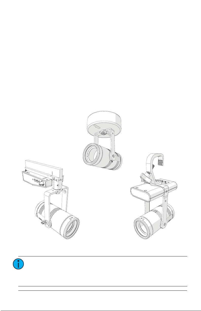
Introduction
PortableTrack-mount
Canopy
The Irideon WLZ (Wash Light Zoom) is a compact but powerful LED wash light.
It incorporates many of the great features of its companion fixture, the
Irideon FPZ, including local and DMX control, adjustable zoom, and sleek
design.
The Irideon WLZ has three available mounting options:
• Track-mount—For use with the DataTrack track system.
• Portable—Includes a miniature C-clamp and yoke-mounted driver, and
has a permanently installed power cord with 3-prong Edison connector.
Region-specific connectors are available. Contact ETC for available
options. Use L5-15 plugs on branch circuits with L5-15 receptacles only.
• Canopy—Available in three different control variants:
-0–10V
- DALI
-DMX
Note:
The miniature C-clamp for the portable fixture is
available only in non-EU markets. Within the EU, use an
M12 bolt to secure a C-clamp (provided separately) to the
fixture.
User Manual 1
Page 6
INSTRUCTIONS PERTAINING TO A RISK OF FIRE, ELECTRIC SHOCK, OR INJURY TO
PERSONS
IMPORTANT SAFETY INSTRUCTIONS
WARNING - To reduce the risk of FIRE, ELECTRIC SHOCK, OR INJURY TO PERSONS:
1) Keep lamp away from materials that may burn.
2) External temperature after 5 minutes of full-brightness operation: 27°C (81°F).
3) External temperature when steady state is achieved: 50°C (122°F).
SAVE THESE INSTRUCTIONS
WARNING:
WARNING:
WARNING:
WARNING:
Please note the following safety warnings before use:
• Do not mount the fixture on or near combustible
surfaces.
• Do not operate the fixture without a lens installed, or
with a scratch or cracked lens. Damaged lenses must be
replaced.
• Use in dry locations only, where humidity does not
exceed 90 percent (non-condensing). These fixtures are
not intended for outdoor use.
For the canopy fixture, turn off power at main fuse or
breaker box and verify that the power is off before
proceeding with installation or maintenance.
The canopy fixture must be installed by a qualified
electrician in accordance with all national and local
electrical and construction codes and regulations.
Use the track-mount fixture with ceiling-mounted track
only.
To reduce the risk of fire and electric shock, use the
track-mount fixture only with the DataTrack (EUTRAC
®
)
track system.
AVERTIR:
Pour éviter le risque d'incendie ou de choc électrique
avec le modèle adaptateur pour rail, utiliser uniquement
avec une alimentation par rail DataTrack (EUTRAC).
2 Irideon WLZ
Page 7

Specifications
Physical
• Steel yoke with 0.406” (10.3 mm) diameter
mounting hole
• IP20 rated
• Magnetically held integrated media holder
for 2-11/16” (69 mm) diameter color media
or diffusion or 1.75 mm-thickness dichroic
glass
• Power at full intensity: 20 W (typical),
24 W (maximum)
• Input voltage options:
- Track-mount and portable: 100–240 V,
50/60 Hz
- Canopy (0–10 V and DALI): 120–277 V,
50/60 Hz
- Canopy (DMX): 100–277 V, 50/60 Hz
• Portable fixture: 6 ft power cable hard-wired
to fixture with mains connector options of
NEMA 5-15P, Schuko, or UK
• Cree LED source
- Irideon WLZ 2700 K Gallery: 90+ CRI
- Irideon WLZ 3000 K: 80+ CRI
- Irideon WLZ 3000 K Gallery: 90+ CRI
- Irideon WLZ 4000 K: 80+ CRI
- Irideon WLZ 5000 K: 80+ CRI
• Integrated beam control
(9–78 degree beam-angle)
• 0°C to 40°C (32°F to 104°F) ambient operating temperature
• Round diffuser for use in integrated media holder (order part number 7192A4025)
• Track-mount fixture:
- Compatible and ETL-listed for DataTrack
(EUTRAC) brand track
- DataTrack color matching track adapter
included
• Portable fixture:
- C-clamp (included in non-EU markets)
- Optional accessory for Unistrut
mounting (order separately, part number
7191K1000)
• Canopy fixture:
- Can be installed directly on 4” and
4-11/16” backboxes, or on backboxes
with round cover plates
- Not for installation on 1-gang backboxes
or trim rings
Electrical
• Inrush (first half-cycle) for 0–10 V and DALI
canopy fixtures:
- 120 V: 2 A
- 240 V: 5 A
- 277 V: 6 A
• Inrush (first half-cycle) for all other fixtures:
- 120 V: 11 A
- 240 V: 24 A
- 277 V: 28 A
• All variants require power from a nondimmable source
LEDs
• Long-life LED: 70,000 hours L70 lumen
maintenance
Optical
• Built-in zoom optics
(16–91 degree field-angle)
Thermal
Accessories
®
User Manual 3
Page 8
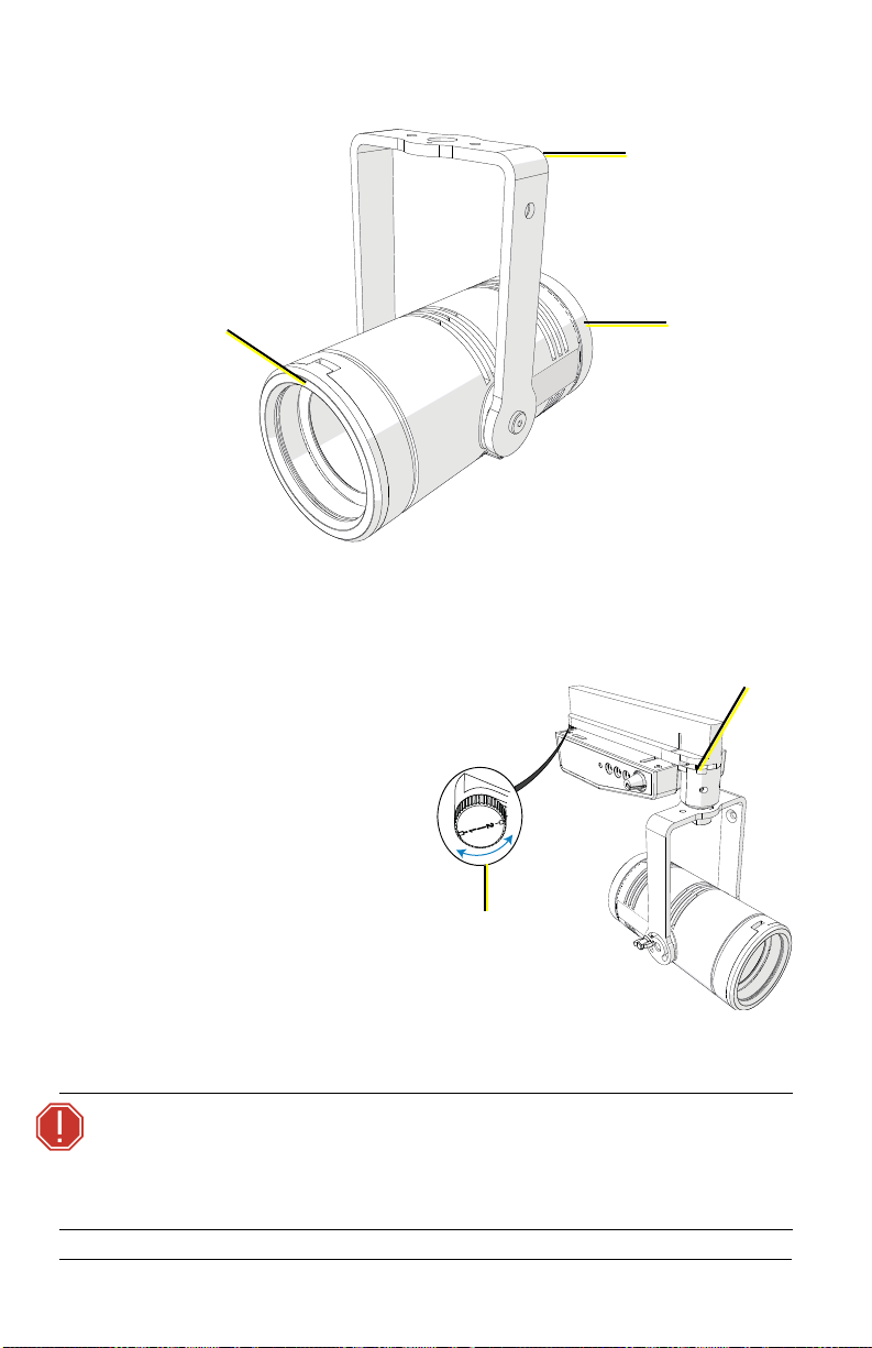
Basic Assembly
Yoke
Integrated media
holder
(Illustration shows fixture body only)
Wide/narrow
field
adjustment
Circuit
selection lock
Locking
mechanism
Installation
Install TrackMounted Fixture
1: Insert the DataTrack
adapter into the track.
The adapter only fits into
the track one way with
the tabs nesting into the
track’s groove.
2: Rotate the locking
mechanisms to lock the
adapter into place.
3: Use the circuit selection
WARNING:
4 Irideon WLZ
lock to select the circuit.
The desired circuit number should point toward the center of the
adapter.
When using the circuit selection lock, ensure that the
selected circuit is a constant power circuit. Dialing into a
dimmable circuit may cause fixture damage that will void
the ETC warranty.
Page 9
Install Canopy Fixture (DMX variant)
Note:
The canopy fixture can be installed directly on 4” and
4-11/16” backboxes, or on backboxes with round cover
plates. The canopy fixture cannot be installed on 1-gang
backboxes or trim rings.
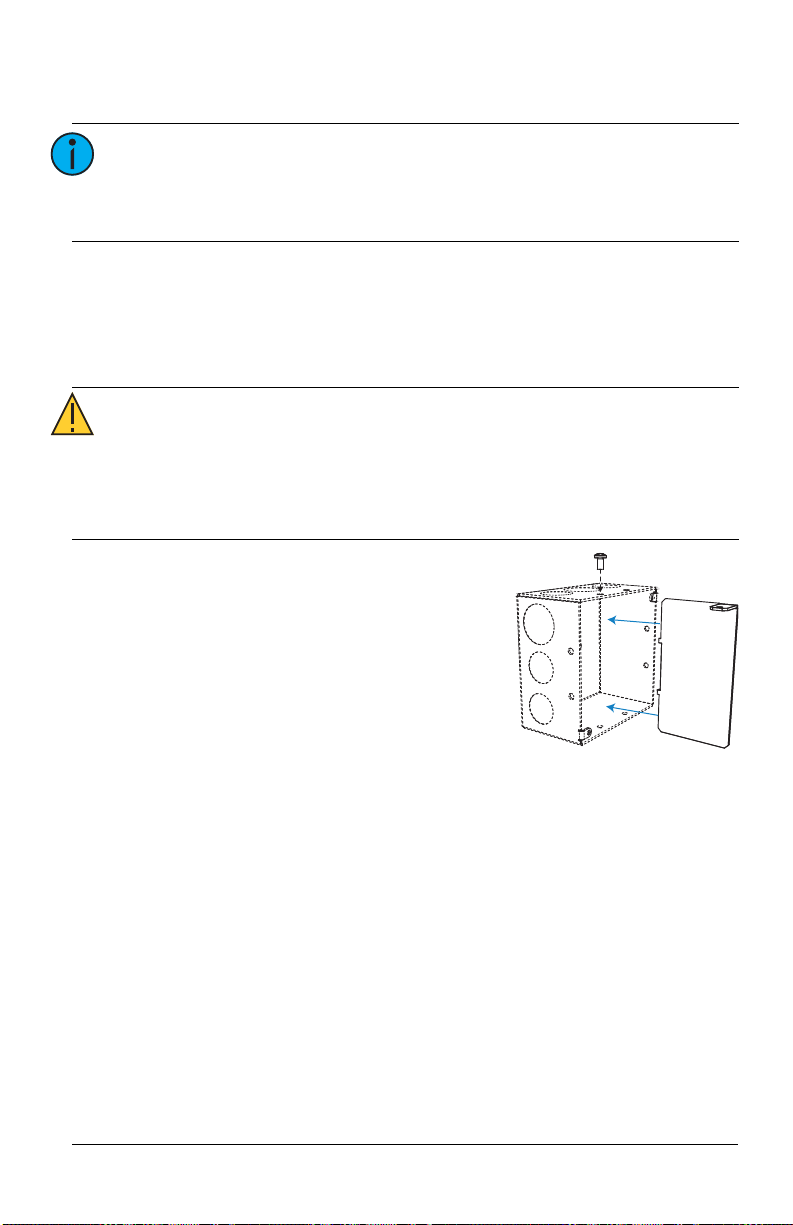
Install the Voltage Barrier (DMX variant)
The DMX variant of the canopy fixture includes a voltage barrier to separate
the data network from the line voltage inside the backbox. Voltage barriers are
provided for both 4” and 4-11/16” backboxes.
CAUTION:
Install the voltage barrier in the backbox with
the provided screw, separating the power
side from the data side (see image at right).
• DMX control is a Class 2 circuit. DMX wiring cannot be
run through the same conduit as line voltage powersupply conductors.
• Separate the line voltage from the data side in the
backbox. Install the voltage barrier provided by ETC.
User Manual 5
Page 10

Connect Canopy Wiring (DMX variant)
Mounting plate
Cover plate
(if needed for
surface-mounting)
From a DMX/RDM source
Data – (Black)
Data + (Red)
Belden 9729 (or equivalent) wire
termination to screw connector
4 to 8 = n/c
COM
Cable preparation instructions for DMX termination are included in the
termination kits, and are also available for free download at etcconnect.com.
1: Remove the adhesive tape or fasteners securing the mounting plate to
the fixture to free the mounting plate from the canopy enclosure.
WARNING:
2: Are you flush-mounting the fixture or surface-mounting the fixture?
• Flush-mounting: Continue to step 3.
• Surface-mounting:
3: Terminate DMX/RDM input from the
control source to the backbox.
If using Belden 9729:
a: See the
b: Install the screw terminal
RISK OF ELECTRIC SHOCK! Install the cover plate as
directed below for installations where the interior of the
canopy enclosure could be exposed after installation
with only the mounting plate. For example, install the
cover plate when installing to a surface-mount backbox.
Position the cover
plate on top of the
mounting plate
before wiring the
fixture. The cover
plate is required
when the interior of the canopy enclosure could be exposed after
installation with only the mounting plate (the mounting surface is
smaller than the canopy enclosure).
DMX Cable Preparation
for Screw Termination Setup
for instructions to prepare
Guide
and terminate Belden 9729 for
DMX input cable to the screw
terminal connector.
connector with wires terminated
to the DMX/RDM Input receptacle
on the termination board.
6 Irideon WLZ
Page 11

If using Category 5:
Data – (ORG)
Data + (W/ORG)
Cat5 (or equivalent) wire
termination to IDC connector
COM
BRN
GRN
W/GRN
BLU
W/BLU
DMX
termination
board
Power block
a: See the
IDC Termination Setup Guide
Cat5 Cable Preparation for
for
instructions to prepare and
terminate Category 5 for DMX/RDM
input cable to the insulation
displacement connector.
b: Install the IDC connector with wires
terminated to the DMX/RDM Input
receptacle on the termination board.
4: Optionally, terminate DMX/RDM thru to
the next device in the DMX data run.
Up to 32 DMX/RDM devices can be
daisy-chained together per data run.
a: See the specific termination setup guide for the type of cable used
(either Belden 9729 or Category 5) in the installation. Termination
kits are ordered separately.
b: Install the connector with wires terminated to the DMX/RDM Thru
receptacle on the termination board.
5: Connect the building ground wire to the power block on the fixture.
6: Following the label on the mounting plate, attach the power wires to
User Manual 7
the power block.
Page 12

Install the Mounting Plate and Complete the
Mounting
plate
Canopy
screws
Mounting
plate screws
Cover plate
(if needed for
surfacemounting)
(DMX variant
shown)
Canopy
screw hole
Mounting plate
(DMX variant)
2
1
2
1
Wiring (DMX variant)
1: Secure the mounting plate (or the
combination of mounting plate and
cover plate for surface-mounting) to
the installed backbox, positioning
the plate so that the power side and
data side are separated by the
voltage barrier in the backbox. See
Install the Voltage Barrier (DMX
variant)
on
page 5
.
For this structure... ...secure mounting plate using:
4-11/16” backbox Large oval slots (see 1 above)
4” backbox Small oval slots (see 2 above)
8 Irideon WLZ
Page 13

5: Terminate DMX/RDM data signal for the last DMX/RDM device in the
Hook
2: Use the hook in the canopy enclosure to hang the
fixture from the mounting plate while you complete
the fixture wiring.
3: If desired, manually set the DMX address on the
fixture using the three addressing dials in the canopy.
See
Set the DMX Address on the Fixture
on
page 15
.
4: Connect the pre-wired DMX connector on the fixture
to the mated connector on the mounting plate
(shown below).
ON
Mounting plate
DMX connector
Termination switch
Power block
Canopy
screws
data run by setting the termination switch to ON (to the right, as shown
below). All other devices in the data run should retain the default
setting for the termination switch (OFF).
6: Following the label on the mounting plate, attach the power wires to
the power block.
7: Use the canopy screws to secure
the fixture to the mounting plate.
CAUTION:
Make sure that the
wiring is clear of the
mounting plate before
you secure the fixture.
User Manual 9
Page 14

8: Insert the oval-shaped covers into the canopy
Oval-shaped covers
Mounting
plate
Canopy
screws
Mounting
plate screws
Cover plate
(if needed for
surfacemounting)
(DALI
variant
shown)
enclosure to cover the canopy screw
openings.
9: Restore power at the disconnect device.
Install Canopy Fixture (0–10 V and DALI variants)
Note:
Note:
WARNING:
The 0–10 V driver conforms to IEC 60929 Annex E. Of the
0–10 V range, use 0–1 V to set the minimum level, and
use 1–10 V for continuous dimming.
The canopy fixture can be installed directly on 4” and
4-11/16” backboxes, or on backboxes with round cover
plates. The canopy fixture cannot be installed on 1-gang
backboxes or trim rings.
RISK OF ELECTRIC SHOCK! Install the cover plate as
directed below for installations where the interior of the
canopy enclosure could be exposed after installation
with only the mounting plate. For example, install the
cover plate when installing to a surface-mount backbox.
1: Remove the adhesive tape or fasteners
securing the mounting plate to the
fixture to free the mounting plate from
the canopy enclosure.
2: Are you flush-mounting the fixture or
surface-mounting the fixture?
• Flush-mounting: Using the mounting
plate screws, secure the mounting
plate to the installed backbox.
• Surface-mounting: Position the cover
plate on top of the mounting plate,
and use the mounting plate screws
to secure both plates to the
installation surface. The cover plate is
required when the interior of the
canopy enclosure could be exposed
after installation with only the
mounting plate (the mounting
surface is smaller than the canopy
enclosure).
10 Irideon WLZ
Page 15

2
1
2
1
Mounting plate
(0–10 V and DALI variants)
3
3
Canopy
screw hole
Hook
For this structure... ...secure mounting plate using:
4-11/16” backbox Large oval slots (see 1 above)
4” backbox Small oval slots (see 2 above)
Mud ring and round box Circular slots (see 3 above)
3: Use the hook in the canopy enclosure
to hang the fixture from the
mounting plate while you complete
the fixture wiring.
4: Connect the building ground wire to
the ground wire on the fixture,
following local electrical codes.
5: Connect the supply power wires to the fixture wiring using the included
®
WAGO
• For 120 V fixtures: Connect the black wire to line and the white
connectors.
wire to neutral.
• For 230 V fixtures: Connect the brown wire to line and the blue
wire to neutral.
6: Connect the data wires to the fixture wiring using the included WAGO
connectors.
• For 0–10 V fixtures: Connect the gray wire to data - and the purple
wire to data +.
• For DALI fixtures: Connect the purple wires to data - and data +.
User Manual 11
Page 16

7: Use the canopy screws to secure the
Canopy
screws
Oval-shaped covers
fixture to the mounting plate.
8: Insert the oval-shaped covers into the
canopy enclosure to cover the canopy
screw openings.
9: Restore power at the disconnect device.
12 Irideon WLZ
Page 17

Install Portable Fixture with C-clamp
Washers
Pipe bolt
C-clamp
Yoke bolt
Spacer
Detail view
of washers
4: Loosen the C-clamp yoke
bolt and rotate the yoke to
the desired position.
5: Tighten the bolt to lock the
fixture.
The C-clamp attaches the fixture to the mounting pipe and allows you to
adjust the position of the fixture once it is mounted. The C-clamp will fit a
3/4” to 2” pipe. Two different length pipe bolts are provided to accommodate
different pipe sizes.
Note:
The miniature C-clamp is available only in non-EU
markets. Within the EU, use an M12 bolt to secure a
C-clamp (provided separately) to the fixture.
1: Insert the spacer into the driver box through the hole in the top of the
yoke.
2: Tightly fasten the C-clamp to the yoke with the provided yoke bolt and
washers.
3: Place the C-clamp on the mounting pipe, and then tighten the pipe bolt
to secure it. Use the standard pipe bolt to secure the fixture to larger
mounting pipes. If necessary, exchange the standard pipe bolt for the
longer pipe bolt (included) to secure the fixture to smaller mounting
pipes.
CAUTION:
Tighten the C-clamp pipe bolt to about 18 in/lb
(approximately finger-tight plus up to one-quarter turn).
Do not use excessive force.
User Manual 13
Page 18

Install Portable
Washers
Yoke bolt
Spacer
Fixture on Unistrut
Track
You can install the portable
fixture on Unistrut track using
the Irideon FPZ Unistrut Kit
(7191K1000).
1: Insert the spacer into
the driver box through
the hole in the top of
the yoke.
2: Use the yoke bolt and
washers to fasten the
fixture to the Unistrut
track.
Within the EU, use an
M12 bolt and
appropriate washers in
place of the provided
kit hardware.
Connect Cables to Portable Fixture
1: Connect RJ45 data cables to the top of the driver box, one for data in
and one for data thru (in either position), as needed.
• To order RJ45-to-female XLR adapter, use part number W6538.
• To order RJ45-to-male XLR adapter, use part number W6539.
2: Connect the fixture to the power source.
Note:
• The Irideon WLZ is not self-terminating. You must
terminate the last fixture in line with a 120 Ohm
resistor. Please contact your ETC customer service
representative to purchase part number N4086.
• No more than 32 DMX devices can be daisy-chained
together on a single run. For runs of fixtures totaling
more than 32 DMX devices, use a DMX splitter to split
the DMX runs.
• When using DMX over Cat5, use Cat5e or better. Cable
distance must not exceed 300 m (1000 ft).
• The Irideon WLZ cannot be controlled via network
protocols and should not be connected to a system
network.
14 Irideon WLZ
Page 19

Portable Fixture DMX Pinout
Pin Wire Color Description
1 White/orange DMX1 +
2 Orange DMX1 -
3 White/green DMX2 +
4 Blue Not Connected
5 White/blue Not Connected
6Green DMX2 -
7 White/brown Iso Common
8 Brown Iso Common 2
Set the DMX Address on the Fixture
You can set the DMX address using RDM, but you can also set the DMX
address on the fixture itself, if necessary. The fixture uses the last address that
you set, regardless of whether you set it via RDM or locally on the fixture.
There are three addressing dials on the track adapter (track-mounted fixture),
in the canopy (canopy fixture), or on the driver box (portable fixture). To set
the DMX address, use a small flat-head screwdriver to move the arrow to the
desired address number.
User Manual 15
Page 20

DMX addresses must be set between 1 and 512. Each fixture must be
Local intensity
control knob
Status LED and
DMX addressing dials
Portable
Track-mount
1'S
6
5
4
3
2
1
0
9
8
7
6
5
4
3
2
1
0
9
8
7
6
5
4
3
2
1
0
9
8
7
1'S
6
5
4
3
2
1
0
9
8
7
6
5
4
3
2
1
0
9
8
7
6
5
4
3
2
1
0
9
8
7
10'S
100'S
10'S
100'S
Canopy (mounting
plate removed)
In these addressing
examples, the fixture
is addressed to 503.
considered a separate DMX device for the purpose of DMX line-loading
calculations. The Irideon WLZ only has an intensity channel.
3
4
2
5
1
6
0
7
9
8
3
4
2
5
1
6
0
7
9
8
3
4
2
5
1
6
0
7
9
8
Note:
When using RDM with track-mounted fixtures, ETC
recommends connecting no more than 20 fixtures on a
single run.
16 Irideon WLZ
Page 21

Alternative DMX Addressing Functions
Certain DMX addresses are reserved for special functions. Addresses 700 and
above can be used for setting the intensity level of the fixture. The second and
third address numbers set the intensity level. The intensity knob is ignored
when using these DMX addresses. See the following table for examples:
DMX Address Function
701 Intensity at 1%
710 Intensity at 10%
725 Intensity at 25%
799 Intensity at 99%
800 Intensity at 100%
Adjust the Local Intensity
A local intensity knob is located on the track adapter (track-mounted fixture)
or on the driver box (portable fixture). See the illustration in
Address on the Fixture
On the canopy fixture (DMX variant only), the local intensity adjustment
control is located on the side of the canopy (next to the status LED). To adjust
the local intensity knob on the canopy fixture, you will need a small flat-head
screwdriver (jeweler’s screwdriver).
You can adjust the local intensity with or without DMX being present.
• When DMX is not present, you can control the intensity.
• When DMX is present, you can set the maximum light output. Dimming
will be proportional in relation to that setting. When the local intensity
is set to Off, the maximum light level over DMX is 100%.
• When DMX is lost and the local intensity is set to Off, the light will go
dark.
• When DMX is lost and the local intensity is set to a level greater than 0,
the light goes to the level of the local intensity setting.
on
page 15
.
Set the DMX
User Manual 17
Page 22

Initial Power Up
Track-Mount, Portable, and Canopy (DMX) Fixtures
Control and configure the fixture over a DMX/RDM control network or directly
from a connected computer running appropriate software. When controlling
the fixture directly from a PC, a Gadget II interface or DMX/RDM gateway is
required.
Note:
Changing the address via RDM will override the local
DMX addressing dials. However, if you change the
addressing dials after you set the address via RDM, the
addressing dials will override the RDM setting. See Set the
DMX Address on the Fixture on page 15.
Canopy (0–10 V) Fixture
Apply power and dim the fixture using a 0–10 V controller.
Note:
The 0–10 V driver conforms to IEC 60929 Annex E. Of the
0–10 V range, use 0–1 V to set the minimum level, and
use 1–10 V for continuous dimming.
Canopy (DALI) Fixture
Use a DALI configuration and commissioning tool to configure the DALI
address of the fixture.
Status LED
The status LED indicates the DMX status. When DMX is present, the LED turns
on for 10 seconds, and then it turns off.
Note:
A change to the DMX start address, the local intensity, or
the presence of DMX will “wake” the status LED.
When the local intensity is set to Off, the status LED will flash when there is a
loss of DMX.
With the local intensity set to any other position, the status LED will flash for
10 seconds when there is a loss of DMX. Then the LED will turn off.
18 Irideon WLZ
Page 23

Adjustments
Yoke
locking
knob
Field angle
markers
Set the Angle with the Yok e
1: Loosen the yoke locking knob.
Do not remove the knob.
2: Tilt the fixture to the desired
position.
3: Tighten the yoke locking knob
to secure the position.
Adjust the Field
Rotate the back of the fixture body to adjust the
field between wide and narrow (see image at
right). The field angle markers on the side of the
fixture indicate the field angle as you adjust
within the range of 16–91 degrees.
User Manual 19
Page 24

Use the Barn Door Accessory
Snap the barn door accessory onto the front of the fixture body as shown
below. Do not remove the media holder from the front of the fixture before
installing the accessory—the barn doors snap directly on the front of the
fixture with the media holder in place.
Rotate the accessory and adjust the doors as needed.
CAUTION:
When removing the barn door accessory, firmly hold the
fixture body in order to avoid unnecessary stress on the
DataTrack adaptor, C-clamp, or canopy.
Use the Integrated Media Holder
The Irideon WLZ comes equipped with an integrated media holder, which is a
metal frame used to hold color media (often referred to as gel) or diffusion in
front of the lens. The media holder is equipped with a magnetic retaining clip
that prevents the media from falling out. The integrated media holder can take
color media, diffusion, or dichroic glass with a 2-11/16” (69 mm) diameter.
ETC provides a diffuser to create additional diffusion for a super-soft beam. To
use this accessory, order part number 7192A4025 and install it in the
20 Irideon WLZ
integrated media holder.
WARNING:
Make sure the media holder is locked in position with the
magnetic retaining clip.
Page 25

Install Color Media or Diffusion
Integrated
media holder
Dichroic
glass
Magnets
1: Release the magnetic retaining clip by gently pushing it up.
2: Insert the media.
3: Replace the media holder by aligning the tab at the top of the media
holder with the inset on the front casting.
Install Dichroic Glass
The integrated media holder
accommodates 1.75 mm-thickness
dichroic glass.
1: Release the magnetic retaining
clip by gently pushing it up.
2: Place the dichroic glass into the
groove.
3: Replace the media holder by aligning the tab at the top of the media
holder with the inset on the front casting.
User Manual 21
Page 26

Clean the Lens
Integrated
media holder
Front
casting
Lens
Four screws
WARNING:
Do not use ammonia-based or other harsh commercial
cleaners. Clean lens only as directed.
Commercially available glass cleaning agents should be
avoided as they may contain ammonia, other harsh
chemical detergents, or abrasive agents. These cleaners
may damage the lens surface. Do not immerse or soak the
lens in any cleaning solution.
1: Remove the integrated media holder.
2: Use a Phillips screwdriver to remove the three screws from the front of
the fixture.
3: Remove the front casting.
4: Remove the lens.
5: Remove dust with a blast of oil-free air or wipe with a clean, lint-free
cloth.
6: Replace the lens. Ensure that the ridged side of the lens is facing out.
7: Replace the front casting and secure it with the screws.
8: Replace the integrated media holder.
22 Irideon WLZ
Page 27

RDM Values
Manufacturer ID: 0x6574 (Electronic Theatre Controls)
Model ID: 0x901 (Irideon WLZ)
Parameter RDM PID Value
DMX Start
Address
Personality ID 0x00E0
Output
Frequency
0x00F0 Range = 1–512
0x8123
1 = DMX
2 = Local
0 = Standard (1.2 kHz)
1 = High (25 kHz)
User Manual 23
Page 28

Corporate Headquarters Middleton, WI, USA +1 608 831 4116
London, UK +44 (0)20 8896 1000 Holzkirchen, DE +49 (80 24) 47 00-0
Rome, IT +39 (06) 32 111 683 Hong Kong +852 2799 1220 Paris, FR +33 1 4243 3535
Web etcconnect.com Support support.etcconnect.com Contact etcconnect.com/contactETC
© 2019 Electronic Theatre Controls, Inc.
Product information and specifications subject to change. ETC intends this document to be
provided in its entirety. Trademark and patent info: etcconnect.com/ip
7192M1200-1.0.1 Rev D Released 2019-06
 Loading...