

Page 1
Copyright © 2016 Electronic Theatre Controls, Inc.
All rights reserved. Product information and specifications subject to change.
Part Number: 7191M1200-1.0.0 Rev: A
Released: February 2016
Irideon
™
FPZ
User Manual
Rev A
Page 2

ETC®, Eos®, and Unison® are either registered trademarks or trademarks of
Electronic Theatre Controls, Inc. in the United States and other countries.
All other trademarks, both marked and not marked, are the property of their
respective owners.
ETC intends this document, whether printed or electronic, to be provided in its
entirety.
Page 3

Table of Contents
Introduction . . . . . . . . . . . . . . . . . . . . 1
Specifications . . . . . . . . . . . . . . . . . . . 2
Basic Assembly . . . . . . . . . . . . . . . . . . 3
Installation . . . . . . . . . . . . . . . . . . . . . 3
Addressing . . . . . . . . . . . . . . . . . . . . . . 4
Initial Power Up . . . . . . . . . . . . . . . . . .5
Status LED . . . . . . . . . . . . . . . . . . . . . .5
Adjustments . . . . . . . . . . . . . . . . . . . . 5
Adjusting the Yoke Position . . . . . . . . 5
Shaping the Beam . . . . . . . . . . . . . . . . 6
Rotating The Lens Barrel. . . . . . . . . . .7
Integrated Media Holder . . . . . . . . . .8
Cleaning the Glass Lens. . . . . . . . . . . 9
Page 4

Page 5
User Manual 1
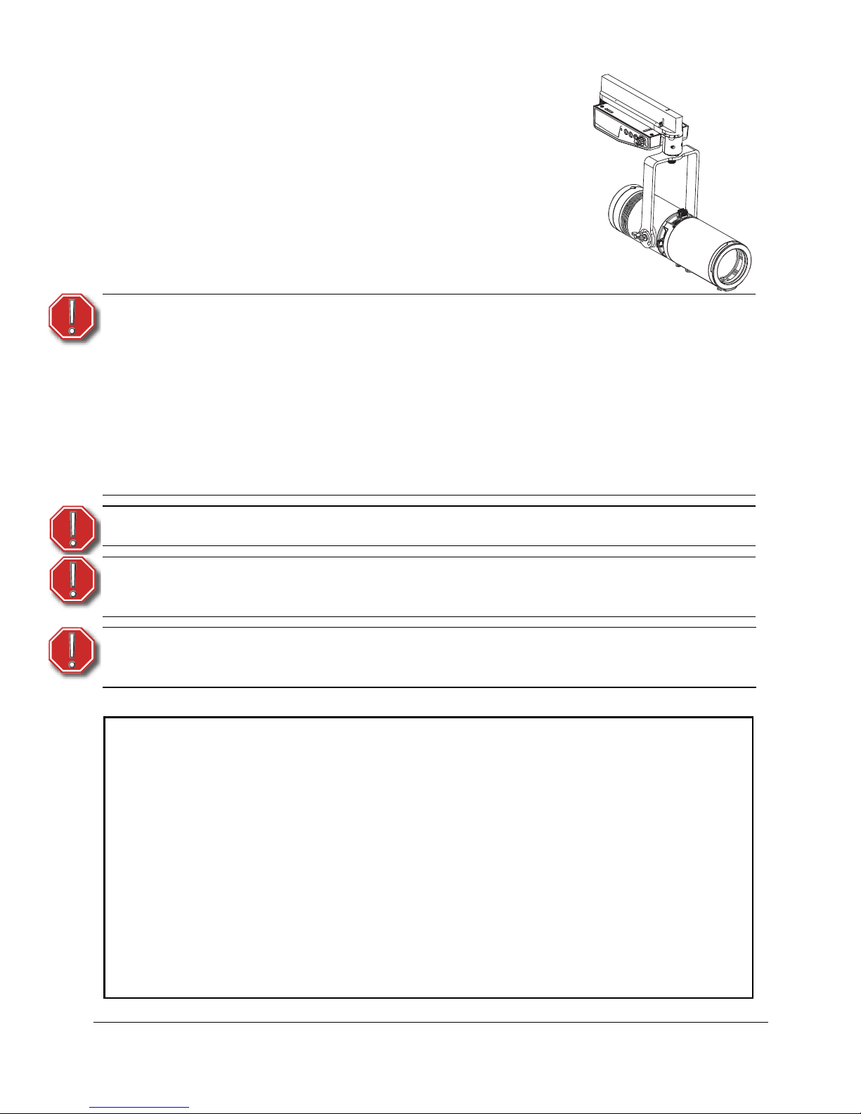
Introduction
The Irideon FPZ takes the beauty and punch of the Source
Four Mini beam and puts it into a fixture designed to work
in any architectural environment. With built in zoom optics,
three-plane shutters and a rotating barrel, the FPZ can
create a sharp or soft focused light in any shape you need.
When used with either glass or metal gobos, logos and
designs look great. With the addition of local level control
as well as individual DMX addressing, the Irideon FPZ can
do it all, and look great while doing it.
WARNING:
Please note the following safety warnings before use:
Do not mount the fixture on or near combustible surfaces.
Do not operate the fixture without a lens installed, or with
a scratch or cracked lens. Damaged lenses must be
replaced.
Use the Irideon FPZ fixture in dry locations only, where
humidity does not exceed 90 percent (non-condensing).
These fixtures are not intended for outdoor use.
WARNING:
Use with ceiling-mounted track only.
WARNING:
To reduce the risk of fire and electric shock, use the track
mount version only with the EUTRAC track system.
AVERTIR:
Pour éviter le risque d'incendie ou de choc électrique
utiliser seulement avec une alimentation par rail EUTRAC.
INSTRUCTIONS PERTAINING TO A RISK OF FIRE, ELECTRIC SHOCK, OR INJURY TO
PERSONS
IMPORTANT SAFETY INSTRUCTIONS
WARNING - To reduce the risk of FIRE, ELECTRIC SHOCK, OR INJURY TO PERSONS:
1) Keep lamp away from materials that may burn.
2) External temperature after 5 minutes of full-brightness operation
34°C (93°F)
3) External temperature when steady state is achieved 54°C (129°F).
SAVE THESE INSTRUCTIONS
Page 6

2 FPZ
Specifications
Physical • IP20 rated
• Die-cast aluminum construction (A380
grade)
• Magnetically held media holder
• Fine-texture, high-temperature powdercoated paint
• Zoom range to suit a variety of throw
distances
• Steel yoke with 0.406” diameter
mounting hole
• Tool-free tilt and beam adjustment
• Rotating shutter assembly ±175°
• High-impact resistant, thermally
insulated knobs and shutter handles
• E-size gobo pattern holder (included)
37.5mm with a 25.4mm image area
• Captive accessory slot for pattern
holder (included)
• Track mount
-- Compatible and ETL-listed for DataTrack
(EUTRAC) brand track
-- DataTrack color matching track adapter
included
• Locking, stainless steel, full hard
shutters in a tri-plane assembly,
0.40mm (A301 grade)
Electrical • Power at full intensity: 20W max
• Input voltage options:
-- 100-240V, 50/60Hz
• Inrush (first half-cycle)
-- 120V: 11A
-- 240V: 24A
LEDs
• Long-life LED: 35,000 hours L70
lumen maintenance
• Cree LED source
-- Irideon FPZ 3000K: 80+ CRI
-- Irideon FPZ 3000K Gallery: 90+ CRI
-- Irideon FPZ 4000K: 80+ CRI
-- Irideon FPZ 5000K: 80+ CRI
Optical
• Beam edge continually adjustable
hard to soft
• Built-in zoom optics (25-50 degree fieldangle)
• Projector-quality, high-contrast lenses
Thermal
• 0°C to 40°C (32°F to 104°F) ambient
operating temperature
Page 7

User Manual 3
Basic Assembly
Installation
Step 1: Insert the DataTrack adapter
into the track. The adapter only
fits into the track one way with
the tabs nesting into the track’s
groove.
Step 2: Rotate the locking mechanisms
to lock the adapter into place.
Step 3: Use the circuit selection lock to
select the circuit. The desired
circuit number should point
toward the center of the
adaptor.
Step 4: Focus the fixture. See Adjustments on page 5.
WARNING:
When using the circuit selection lock, ensure the
selected circuit is a constant power circuit. Dialing into
a dimmable circuit may cause fixture damage that will
void the ETC warranty.
Yoke
Integrated Media
Holder
Shutters x4
Beam Zoom and
Focus Knobs
Pattern Holder
Slot
Circuit
Selection
Lock
Locking
Mechanism
Page 8

4 FPZ
Addressing
Fixture addresses must be
set between 1 and 512.
There are three addressing
dials on the track adapter.
To address, use a small flat
head screwdriver to move
the arrow to the desired
address number.
Each Irideon FPZ fixture must
be considered a separate
DMX device for the purpose
of DMX line-loading
calculations. The Irideon FPZ
only has an intensity
channel.
Alternative DMX Addressing Functions
Certain DMX addresses are reserved for special functions. Addresses 700 and above
can be used for setting the intensity level of the fixture. The second and third address
numbers set the intensity level. The intensity knob is ignored when using these DMX
addresses. See the following chart for examples:
Note:
No more than 32 DMX devices can be daisy-chained
together on a single run. For runs of fixtures totaling more
than 32 DMX devices, a DMX splitter will need to be used to
split the DMX runs.
When using RDM with track fixtures, ETC recommends
connecting no more than 20 fixtures on a single run.
DMX Address Function
701 Intensity at 1%
710 Intensity at 10%
725 Intensity at 25%
799 Intensity at 99%
800 Intensity at 100%
3
2
1
0
9
8
7
6
5
4
3
2
1
0
9
8
7
6
5
4
3
2
1
0
9
8
7
6
5
4
Local Intensity
Control Knob
DMX Addressing
Dials
Status LED
In this addressing example, the fixture is
addressed to 503.
Page 9

User Manual 5
Using the Local Intensity Knob
A local intensity knob is located on the track adapter. This can be used to adjust the
intensity with or without DMX being present.
• When DMX is not present, the intensity will be controlled by the knob.
• When DMX is present, the maximum light output can be set by the knob.
Dimming will begin from that setting. When the knob is set to off, the
maximum light level over DMX is 100%.
• When the knob is set to off, data loss behavior is instant, and the light will go
dark.
When the knob is set to a level greater than 0, the data loss behavior goes to the
setting of the local knob.
Initial Power Up
Control and configuration of the Irideon FPZ can be achieved over a DMX/RDM
control network, or directly from a connected computer running appropriate
software. When controlling the Irideon FPZ directly from a PC, a Gadget Interface or
DMX/RDM gateway is required.
Status LED
The status LED indicates the DMX status. When DMX is present, the LED will be on
solid for 10 seconds, and then it will go into an off time out state.
When the local intensity knob is set to off, the status LED will flash when there is a
loss of DMX.
With the local intensity knob set to any other position, the status LED will flash for 10
seconds when there is a loss of DMX. Then the LED will go into an off time out state.
Adjustments
Adjusting the Yoke Position
The Irideon FPZ provides multi-positioning capabilities within its yoke for overall
fixture angle.
Note:
Changing the address via RDM will override the local DMX
addressing dials. However after the address has been set via
RDM, changing the dials will then override the RDM setting.
Note:
Changing the DMX start address, the local intensity knob, or
a change in DMX presence will wake the status LED from its
time out state.
Page 10

6 FPZ
Setting the angle with the
yoke
Step 1: Loosen the yoke locking knob.
Do not remove the knob.
Step 2: Tilt the fixture to the desired
position.
Step 3: Tighten the yoke locking knob
to secure position.
Zooming and Focusing
the Beam
Step 1: Loosen the beam
focus or zoom knob
located under the
barrel. Do not remove
the knob(s).
Step 2: Slide the lens forward
or backward to
achieve the desired
beam edge or angle.
Step 3: Once the fixture is focused, tighten the knob(s).
Shaping the Beam
The beam can be shaped using the four shutters or with a pattern.
The Irideon FPZ has four shutters: left, right, top, and bottom. Each shutter can be
pulled out or pushed in to create the desired beam shape.
Once the shutters are set, you can lock the shutters in place by using a 3mm Allen
wrench (provided).
Yoke
Locking
Knob
Beam Focus
Knob
Zoom Knob
Shutter Lock
Page 11

User Manual 7
Rotating The Lens Barrel
Step 1: Unlock the rotating barrel lock
using the 2mm Allen wrench
(provided).
Step 2: Rotate the barrel to the desired
location.
Step 3: Lock the rotating barrel lock
using the 2mm Allen wrench
(provided).
Rotating Barrel
Lock
Pattern Projection
The Irideon FPZ has a pattern holder slot on the top side
of the shutter barrel, in front of the shutter. It
accommodates an E-size (37.5mm with a 25.4mm
image area) pattern. The maximum pattern thickness
that can be accommodated is 4mm (0.158”).
When the slot is not in use, a small plastic cover
prevents light leakage.
Step 1: Slide the cover knob completely to the
side to expose the slot.
Step 2: Insert the pattern holder.
Step 3: Slide the slot cover back toward the
shutters until it meets the pattern
handle. Leave enough space to move
the handle.
1” Diameter
Page 12

8 FPZ
Integrated Media Holder
The Irideon FPZ comes equipped with an integrated media holder, which is a metal
frame used to hold color media (often referred to as gel) or diffusion in front of the
lens. The media holder is equipped with a magnetic retaining clip that prevents the
media from falling out. The integrated media holder can take color media or diffusion
with a 3” diameter.
Step 1: Release the magnetic retaining clip by
gently pushing it up.
Step 2: Insert the media.
Step 3: Replace the media holder by lining up
the magnets.
Installing Dichroic Glass
.
Step 1: Release the magnetic
retaining clip by gently
pushing it up.
Step 2: Place the dichroic glass into
the groove.
Step 3: Replace the media holder by
lining up the magnets.
WARNING:
Make sure the media holder is locked in position with
the magnetic retaining clip.
Magnetic
Retaining
Clip
Integrated
Media
Holder
Dichroic
Glass
Orange
Rubber
Pads
Magnet
Page 13

User Manual 9
Cleaning the Glass Lens
A fixture diagram is available on page 10.
Step 1: Remove the integrated media holder.
Step 2: Use a Phillips screwdriver to remove the three screws from the front
of the fixture.
Step 3: Remove the front casting and the metal shaft.
Step 4: Remove the light block bracket.
Step 5: Remove the lens adjustment knobs.
Step 6: Remove the front and rear lens holders.
Step 7: Remove dust with a blast of oil-free air or wipe with a clean, lint-free
cloth. Isopropyl alcohol, distilled water, or a 50%-50% mixture of
each can be used to clean the glass surface.
Step 8: Replace the lens.
Step 9: Replace the lens adjustment knobs.
Step 10: Replace the light block bracket. Make sure that it fits into its pocket
of each lens.
Step 11: Replace the metal shaft if you have not previously done so.
Step 12: Replace the front casting.
Step 13: Replace the three screws, which hold the casting onto the fixture.
Step 14: Replace the integrated media holder.
WARNING:
Do not use ammonia-based or other harsh commercial
cleaners. Clean lens only as directed.
Commercially available glass cleaning agents should be
avoided as they may contain ammonia, other harsh
chemical detergents, or abrasive agents. These cleaners
may damage the glass surface and the Anti-Reflective
coatings. Do not immerse or soak the glass in any
cleaning solution.
Note:
You may find it easier to insert the metal shaft into its pocket
of each lens before replacing the lens.
Page 14

10 FPZ
Integrated
Media
Holder
Front
Casting
Metal
Shaft
Light Block
Bracket
Front
Lens
Rear
Lens
Lens Adjustment
Knobs
Three
Screws
Page 15

Page 16

Corporate Headquarters Middleton, Wisconsin, USA Tel +608 831 4116 Service: (Americas)
service@etcconnect.com
London, UK Tel +44 (0)20 8896 1000 Service: (UK)
service@etceurope.com
Rome, IT Tel +39 (06) 32 111 683 Service: (UK)
service@etceurope.com
Holzkirchen, DE Tel +49 (80 24) 47 00-0
Service: (DE)
techserv-hoki@etcconnect.com
Hong Kong Tel +852 2799 1220 Service: (Asia)
service@etcasia.com
Web:
www.etcconnect.com Copyright © 2016 ETC. All Rights Reserved.
Product information and specifications subject to change
. ETC intends this document to be provided in its entirety.
7191M1200-1.0.0 Rev A Released 2016-02
 Loading...