

Page 1
Power Up and Final focus
29. Apply power to start lamp.
Note: The luminaire calibration process will drive all filters to an open
position. The luminaire will remain in this state until data is present.
Allow seven minutes for lamp to reach operating temperature.
30. Focus luminaire as follows:
a Tilt head assembly to adjust for elevation.
b Turn stanchion to adjust left/right orientation.
c Tighten Allen head screw in tilt tube clamp securely.
d Power unit off.
e Remove stanchion cap.
f Tighten 1-1/4 inch nut securely. Tilt tube clamp should hold
head in place while tightening.
g Replace stanchion cap (ensure gasket forms good seal).
h Tighten nuts or bolts on stanchion base securely.
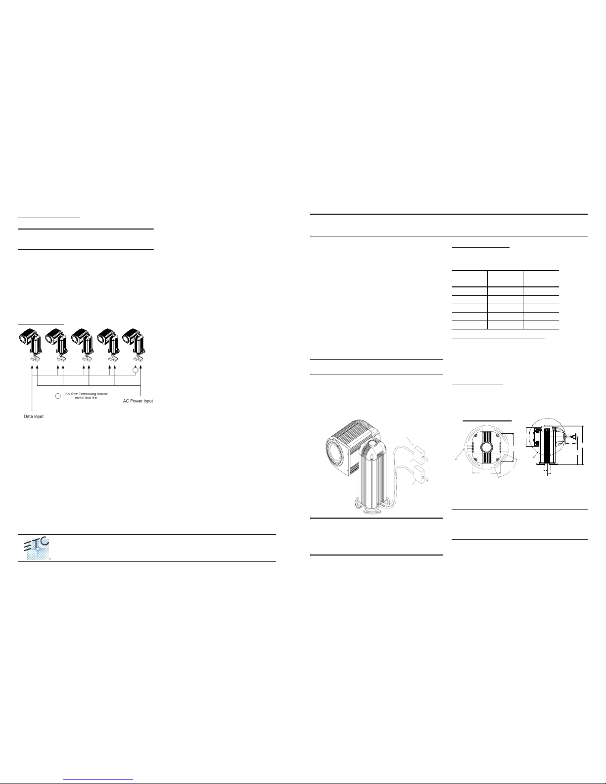
Sample wiring riser
Technical Assistance
The AR500 is a low maintenance luminaire, but in the event of
malfunction, troubleshooting and repair procedures have been
included in the owners manual. For further assistance regarding
the AR500 luminaire, please contact Electronic Theatre Controls
Technical Support staff at one of the offices identified below.
Americas
ETC Americas
Technical Services Department
3030 Laura Lane
Middleton, WI 53562
phone: (608) 831-4116
toll free: (800)775-4382
email: service@etcconnect.com
Europe
ETC Europe Ltd.
Technical Services Department
5 Victoria Industrial Estate
Victoria Road
London, W3 6UU England
phone: +44 (0)208 896 1000
email: service@etceurope.com
Asia
ETC Asia, Ltd.
Technical Services Department
Room 605-606
Tower III, Enterprise Square
9 Sheung Yuet Road
Kowloon Bay, Kowloon, Hong Kong
phone: +852-2799-1220
email: service@etcasia.com
Before Starting
The AR500 luminaire head and stanchion are packed in two separate cartons. Lamps (if purchased), manuals, full lens set, tool kit
and accessories are packed in a third box. The tool kit (part#
7091K4009) includes the following items:
• 1-15/16 inch wrench
• 3/16”x9” T-handle Allen wrench
• 100 Ohm Termination resistor
• Depinning tool
Items also required, but not supplied:
• #2 Phillips screwdriver
• 5/32 Allen wrench
• Two waterproof junction boxes with terminal strips (or one barriered waterproof junction box) for each luminaire.
• Stanchion mounting hardware: 4 each 3/8-18 or M10 studs,
nuts, flat and lock washers.
• Ohm meter
Site Preparation
Note: The installation contractor is responsible for compliance with
local electrical codes.
The luminaire stanchion is provided with 10 feet (3m) of data inputcable and 10 feet (3m) of power input cable for external termination.
Use separate waterproof junction boxes (or a single barriered
waterproof junction box) to connect data and AC power cabling to
each luminaire. Use terminal strips to connect data wiring inside
junction boxes.
CAUTION: This equipment contains sensitive electronic components that require electrical isolation during installation and operation. DO NOT arc weld on
mounting platform with electronics assembly installed in
luminaire stanchion.
AC Power requirements
The AR500 luminaire is available in voltages ranging from 100VAC to
277VAC. Each AR500 luminaire requires 900 watts of power at the
specified voltage and frequency.
AC Power and Data wire requirements
AC Power Input:
Wire Gauge: 16AWG 3-conductor (*1.5mm2X3-conductor)
* European “CE” model
Data Input:
Belden 9729 or equivalent - 22AWG 2-shielded twisted pairs with
drain wire.
Stanchion Placement
The AR500 luminaire stanchion mounts using 3/8-18 inch (M10)
hardware placed in a 10-1/8 inch (257mm) square pattern. When
using a concrete platform, the studs should be at least 4 inches
(100mm) deep. As shown below, the slots in the stanchion base allow
the unit to rotate 45 degrees.
The luminaire head tube is installed through a hole in the side of the
stanchion. The luminaire head rotates 348 degrees from stop to stop.
Allow at least eight inches (203mm) clearance behind the luminaire
head for lamp removal and replacement.
WARNING: Do Not install the luminaire stanchion up
side down. The internal electronics are designed to be
mounted in an upright position. Serious injury may result
if stanchion is mounted incorrectly.
Junction Box
AC
Data
At Voltage
Current at
Startup
Current at
Run
100V 24A 8A
120V 21A 7A
208V 12A 4A
240V 10A 3.5A
277V 9.75A 3.25A
(25.7cm)
Stanchion Mounting "Footprint"
10.125
45°
(25.7cm)
10.125
16.000
(40.6cm)
Diameter
13.13"
(33.35cm)
13.00"R.
(33.02cmR)
19.50"
(
4
9.53c
m)
27.50"
(69.85cm)
6
o
6
o
BDC
AR500 SIDE
TILT
STOP
TILT
STOP
8.0
IRIDEON™ AR500™ Exterior Wash Luminaire
Installation Sheet - Standard Version
IM-S
Americas Middleton, Wisconsin • USA • Tel: (+1) 608 831 4116 • Fax: (+1) 608 836 1736 • (+1) 800 775 4382 • service@etcconnect.com
Europe London • United Kingdom • Tel: +44 (0)20 8896 1000 • Fax: +44 (0)20 8896 2000 • service@etceurope.com
Asia Hong Kong • Tel: (+852) 2799 1220 • Fax: (+852) 2799 9325 • service@etcasia.com
International 3030 Laura Lane • Middleton, Wisconsin 53562 • Tel: (+1) 608 831 4116 • Fax: (+1) 608 836 1736 • www.etcconnect.com
Copyright © 2002 Electronic Theatre Controls, Inc., All Rights Reserved.
Product information and specifications subject to change • 7091M1004 • Rev D• Released 09/02
Page 2
Installation
Unpack Shipping Cartons
Note: The stanchion weighs 82 pounds (37.19Kg) or less, depending on voltage configuration. The head enclosure weighs 62 pounds
(28.12Kg) for a total weight of 144 pounds (65.31Kg). The luminaire
requires two people for installation.
1. Remove stanchion and head assembly from cartons.
2. Locate tool kit (provided in additional carton).
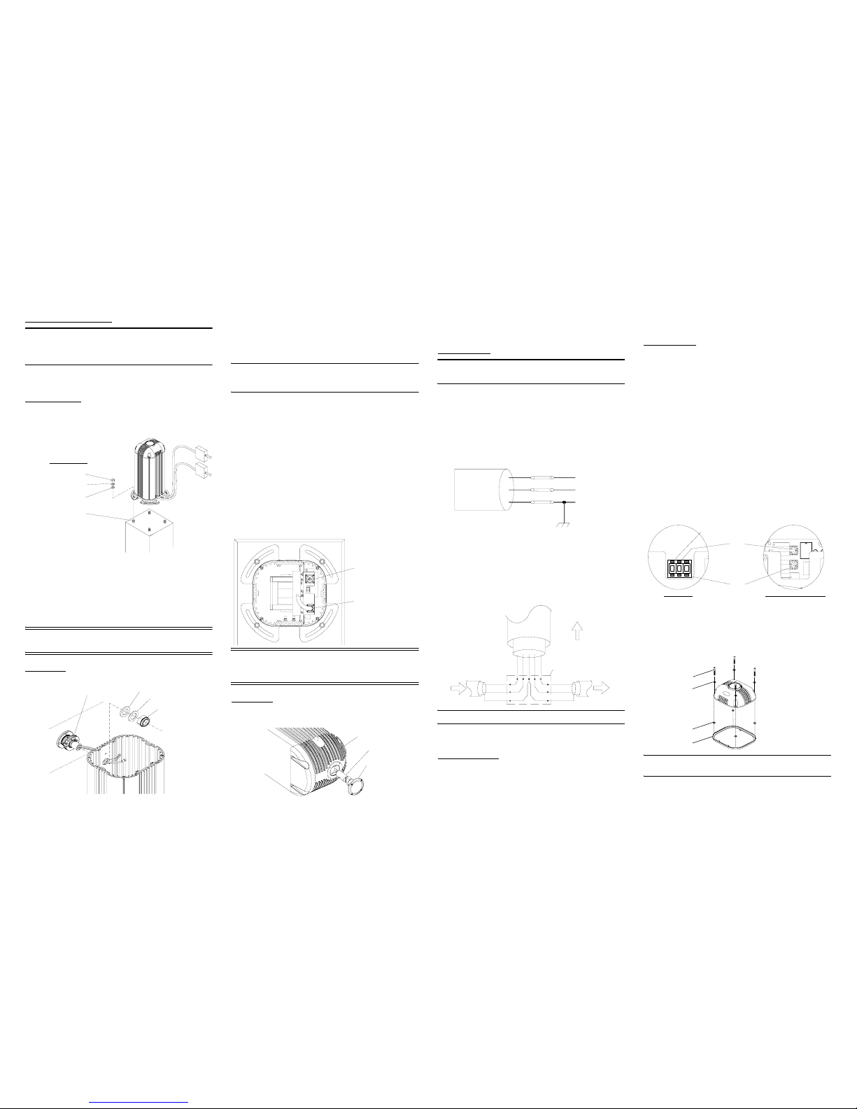
Install Stanchion
3. Set stanchion on mounting pad in appropriate orientation.
4. Loosely install mounting hardware (not provided). See illustra-
tion below.
5. Remove ballast and electronics plate assemblies:
a Remove stanchion cap.
b At ballast assembly, disconnect 3-position AC connector
and Series 30 lamp wire connector. Remove ballast plate.
c At electronics assembly, disconnect 9-position power/data
CPC connector. Remove electronics plate. This connector
should not be reconnected until external wiring is complete
and verified (see “Wiring Verification").
CAUTION: Do not ground to fixture when welding,
open j-boxes.
Install Head
6. At head assembly, remove nut, spring washer, and flat washer
from head enclosure tilt tube and from cables. Ensure black oring stays in tilt tube groove.
7. Dress cables through hole in stanchion.
8. Position grooves in tilt tube clamp facing upwards (head enclo-
sure can later be rotated to face desired direction) and insert
head enclosure tilt tube through hole in stanchion.
Note: The grooves in the tilt tube clamp should fit over the two corresponding ridges running vertically on side of stanchion. Ensure
black o-ring remains in groove of tilt tube.
9. Place flat washer over cables and onto threaded part of tilt
tube. Repeat with wave washer.
10. Dress nut over cables and thread onto tilt tube.
11. Using 1-15/16 inch open-ended wrench (provided), tighten
1-7/8 inch nut only until snug. (The head should rotate when
moved with both hands, yet hold itself in place when left alone.
There should be no gap between tilt tube and stanchion side.)
12. Using 3/16 inch T-handle Allen wrench (provided), loosen Allen
head screw on tilt tube clamp.
13. Rotate head assembly to approximate desired angle.
14. Tighten Allen head screw on tilt tube clamp to hold head
assembly in place.
15. Install ballast plate and connect white 3-position AC lamp wire
connectors.
16. Install electronics plate and connect black 16-position data out
connector.
CAUTION: Do not connect black 9-position elec. input
connector until wiring is complete and verified (See
step 27).
Install Lamp
17. At head assembly, remove rear cap. Ensure O-ring remains
in groove of rear cap.
18. Install lamp in lamp socket. Do not touch the quartz bulb with
bare fingers. If touched, clean quartz bulb with alcohol.
19. Reinstall rear cap on head enclosure, assuring O-ring is still
in-place. Tighten screws in a diagonal cross pattern only until
snug. Then tighten screws in same pattern until tight.
Connect Wiring
WARNING: Remove power from source before connecting junction box wiring.
20. Connect power wires:
a Run three conductor power cable to junction box.
b Cut away extra cable and remove approximately four
inches (100mm) of cable housing.
c Strip and connect three wires to terminal block as follows:
Black (*Brown) = AC Line
White (*Blue) = Neutral
Green (*Grn/Yel) = Ground
*designates European model
21. Connect data wires:
a Run data cable to junction box.
b Cut away extra cable and remove four inches (100mm) of
cable housing.
c Strip and connect data wires to terminal strip as follows:
White/Red = Positive Data
Black/Green = Negative Data
Drain = Ground
Note: See “Sample wiring riser" on back cover.
22. If luminaire is at end of data line, install 100 Ohm resistor (pro-
vided) between positive (red) and negative (green) data lines.
Wiring Verification
23. To verify data wiring:
a Disconnect data line from controller.
b At beginning of data line, or output of data splitter, use
Ohm meter to measure impedance of data line to fixtures.
c Measurement should be approximately 120 Ohms.
d If not, check wiring and termination resistor connection.
e Call tech support (800-688-4116) if problems continue.
24. At stanchion, install ballast and electronics plates and fasten all
connectors except 9-position elec. input CPC connector.
Control System
The AR500 luminaire is controlled with one of two types of electronics plates: DMX only or Composer controller. Both systems recognize luminaires according to the luminaire’s base address channel
setting. The base address channel for each luminaire is assigned
using either a three digit thumbwheel (DMX only) or two rotary
knobs (Composer controller) located on the electronics plate.
25. At the stanchion electronics plate, set luminaire base address
as shown:
DMX Only Address Setting
Each DMX luminaire requires four control channels. Using the three
digit thumbwheel, set each luminaire’s base address four steps
apart, for example:
Luminaire A = Base Address 001, Luminaire B = Base Address
005, Luminaire C = Base Address 009, and so on.
Composer Controller Address Setting
Each Composer luminaire contain two rotary knobs on the control
PCB. One knob controls the ones position and the other controls
the tens position. Unlike the DMX only version, each luminaire base
address is set one position apart. For example, Luminaire A = Base
Address 1, Luminaire B = Base Address 2...
26. Ensure power is stable and continuous:
a All welding near the fixture must be complete.
b J-box doors are sealed.
27. Connect 9-position elec. input connector to electronics plate.
28. Install stanchion cap. Secure cap by tightening four screws in
an alternating cross pattern.
Note: Ensure #10 washers and gasket spacers are installed as pictured above.
3/8-18 (or M10)
Hardware
Nut
Lock Washer
Flat Washer
Mounting Stud
Data Out
16-pos.(black)
Data In
9-pos.(black)
(Do Not Connect Yet!)
WIRING1
<Line
<Neutral
<Ground
BLK
WHT
GRN
BLK
WHT
GRN
10/32x1” Allen screw
#10 flat washer
gasket spacer
gasket
TUBASSY
Tilt Tube
Assembly
Flat Washer
Wave Was her
1-7/8 Inch Nut
Rear Cap
Lamp
Luminaire Head
0
01
+
-
DMX Only
Composer Controller
Ten
One
Hundred (1XX)
WRGDIAG3
To Sta nchi on
To Ne xt
J-Box
J-Box
+Data
-Data
Drain
+Data
-Data
Drain
From Prior
J-Box
Red
White
Green
Drain
Black
Data Cable
 Loading...