

Page 1

Lighting Control Console
Operations Manual
Version 2.0
Copyright © 2013 Electronic Theatre Controls, Inc.
All Rights reserved.
Product information and specifications subject to change.
Part Number:4310M1210-2.00 Rev A
Released: 2013-03
Page 2

ETC®, Eos™,Eos Ti™, Gio®,Ion®, Element™, Emphasis®, Expression®, Insight™, Imagine™,
Focus™, Express™, Unison
®
, Obsession® II, ETCNet2™, EDMX™, Revolution® and Sensor+®,
are either registered trademarks or trademarks of Electronic Theatre Controls, Inc. in the
United States and other countries.
ETC permits the reproduction of materials in this manual only for non-commercial purposes.
All other rights are reserved by ETC.
ETC intends this document, whether printed or electronic, to be provided in its entirety.
Page 3

Table of Contents
Introduction . . . . . . . . . . . . . . . . . . . . . . . . . . 1
Using this Manual. . . . . . . . . . . . . . . . . . . . . . . . . . . . . . . . . . . . . . . .2
Register Your Ion . . . . . . . . . . . . . . . . . . . . . . . . . . . . . . . . . . . . . . . .3
Help from ETC Technical Services . . . . . . . . . . . . . . . . . . . . . . . . . .3
Important Concepts . . . . . . . . . . . . . . . . . . . . . . . . . . . . . . . . . . . . . .4
Channel = Fixture . . . . . . . . . . . . . . . . . . . . . . . . . . . . . . . . . . . .4
Output . . . . . . . . . . . . . . . . . . . . . . . . . . . . . . . . . . . . . . . . . . . . .4
Record Target . . . . . . . . . . . . . . . . . . . . . . . . . . . . . . . . . . . . . . .4
Move Instruction . . . . . . . . . . . . . . . . . . . . . . . . . . . . . . . . . . . . .4
Manual Data . . . . . . . . . . . . . . . . . . . . . . . . . . . . . . . . . . . . . . . .4
Syntax Structure . . . . . . . . . . . . . . . . . . . . . . . . . . . . . . . . . . . . .4
Parameters and Parameter Categories. . . . . . . . . . . . . . . . . . . .5
Tracking vs. Cue Only . . . . . . . . . . . . . . . . . . . . . . . . . . . . . . . . .5
Move Fade. . . . . . . . . . . . . . . . . . . . . . . . . . . . . . . . . . . . . . . . . .6
Block vs. Assert . . . . . . . . . . . . . . . . . . . . . . . . . . . . . . . . . . . . . .6
Live and Blind . . . . . . . . . . . . . . . . . . . . . . . . . . . . . . . . . . . . . . .7
HTP vs. LTP . . . . . . . . . . . . . . . . . . . . . . . . . . . . . . . . . . . . . . . .7
Other Reference Materials . . . . . . . . . . . . . . . . . . . . . . . . . . . . . . . . .8
Help System . . . . . . . . . . . . . . . . . . . . . . . . . . . . . . . . . . . . . . . .8
Online Eos Family (Eos Ti, Eos, Gio and Ion) User Forums . . . .8
Chapter 1
System Overview . . . . . . . . . . . . . . . . . . . . .9
System Components . . . . . . . . . . . . . . . . . . . . . . . . . . . . . . . . . . . .10
Console . . . . . . . . . . . . . . . . . . . . . . . . . . . . . . . . . . . . . . . . . . .10
Remote Processor Unit (RPU). . . . . . . . . . . . . . . . . . . . . . . . . .10
Remote Video Interface (RVI) . . . . . . . . . . . . . . . . . . . . . . . . . .10
Radio Focus Remote (RFR) . . . . . . . . . . . . . . . . . . . . . . . . . . .10
iRFR and aRFR . . . . . . . . . . . . . . . . . . . . . . . . . . . . . . . . . . . . .10
Gateways. . . . . . . . . . . . . . . . . . . . . . . . . . . . . . . . . . . . . . . . . .11
Console Geography . . . . . . . . . . . . . . . . . . . . . . . . . . . . . . . . . . . . .12
Terminology . . . . . . . . . . . . . . . . . . . . . . . . . . . . . . . . . . . . . . . .13
Littlites
Cleaning Ion. . . . . . . . . . . . . . . . . . . . . . . . . . . . . . . . . . . . . . . .14
Outputting DMX . . . . . . . . . . . . . . . . . . . . . . . . . . . . . . . . . . . . .14
Console Capacities . . . . . . . . . . . . . . . . . . . . . . . . . . . . . . . . . . . . .15
Output Parameters . . . . . . . . . . . . . . . . . . . . . . . . . . . . . . . . . .15
Channel Counts . . . . . . . . . . . . . . . . . . . . . . . . . . . . . . . . . . . . .15
Cues and Cue Lists . . . . . . . . . . . . . . . . . . . . . . . . . . . . . . . . . .15
Record Targets . . . . . . . . . . . . . . . . . . . . . . . . . . . . . . . . . . . . .15
Faders . . . . . . . . . . . . . . . . . . . . . . . . . . . . . . . . . . . . . . . . . . . .15
® . . . . . . . . . . . . . . . . . . . . . . . . . . . . . . . . . . . . . . . . . . . . . . . . . . . . . 14
1
Page 4

Chapter 2
System Basics . . . . . . . . . . . . . . . . . . . . . . 17
Setting Up the Hardware . . . . . . . . . . . . . . . . . . . . . . . . . . . . . . . . .18
Power . . . . . . . . . . . . . . . . . . . . . . . . . . . . . . . . . . . . . . . . . . . . . . . .19
Power Up the Console. . . . . . . . . . . . . . . . . . . . . . . . . . . . . . . .19
Power Down the Console . . . . . . . . . . . . . . . . . . . . . . . . . . . . .19
Your First Interaction . . . . . . . . . . . . . . . . . . . . . . . . . . . . . . . . . . . .20
Single Monitor Configuration . . . . . . . . . . . . . . . . . . . . . . . . . . .20
Dual Monitor Configuration . . . . . . . . . . . . . . . . . . . . . . . . . . . .21
The Central Information Area (CIA) . . . . . . . . . . . . . . . . . . . . . . . . .22
Parameter Display . . . . . . . . . . . . . . . . . . . . . . . . . . . . . . . . . . .22
Browser . . . . . . . . . . . . . . . . . . . . . . . . . . . . . . . . . . . . . . . . . . .22
Collapse/Expand the CIA. . . . . . . . . . . . . . . . . . . . . . . . . . . . . .22
Lock the CIA . . . . . . . . . . . . . . . . . . . . . . . . . . . . . . . . . . . . . . .23
Favorite CIA Display . . . . . . . . . . . . . . . . . . . . . . . . . . . . . . . . .23
Locking the Facepanel. . . . . . . . . . . . . . . . . . . . . . . . . . . . . . . .23
Using the Browser . . . . . . . . . . . . . . . . . . . . . . . . . . . . . . . . . . . . . .24
Virtual Keyboard . . . . . . . . . . . . . . . . . . . . . . . . . . . . . . . . . . . .24
Fader Module. . . . . . . . . . . . . . . . . . . . . . . . . . . . . . . . . . . . . . .25
Using Direct Selects . . . . . . . . . . . . . . . . . . . . . . . . . . . . . . . . .25
Direct Selects in Flexi Mode . . . . . . . . . . . . . . . . . . . . . . . . . . .26
Clear Functions . . . . . . . . . . . . . . . . . . . . . . . . . . . . . . . . . . . . .27
Display Control and Navigation . . . . . . . . . . . . . . . . . . . . . . . . . . . .28
Opening and Closing Displays. . . . . . . . . . . . . . . . . . . . . . . . . .28
Selecting Displays . . . . . . . . . . . . . . . . . . . . . . . . . . . . . . . . . . .29
Moving Displays. . . . . . . . . . . . . . . . . . . . . . . . . . . . . . . . . . . . .29
Scrolling within a Display . . . . . . . . . . . . . . . . . . . . . . . . . . . . . .29
Expanding Displays . . . . . . . . . . . . . . . . . . . . . . . . . . . . . . . . . .30
Zooming Displays . . . . . . . . . . . . . . . . . . . . . . . . . . . . . . . . . . .30
Graphical User Interface (GUI) Display Conventions. . . . . . . . . . . .31
Indicators in the Live/Blind Display . . . . . . . . . . . . . . . . . . . . . .31
[Data] Key . . . . . . . . . . . . . . . . . . . . . . . . . . . . . . . . . . . . . . . . .35
[Time] Key . . . . . . . . . . . . . . . . . . . . . . . . . . . . . . . . . . . . . . . . .35
[Label] Key. . . . . . . . . . . . . . . . . . . . . . . . . . . . . . . . . . . . . . . . .35
Using Flexichannel . . . . . . . . . . . . . . . . . . . . . . . . . . . . . . . . . .36
Indicators in the Playback Status Display . . . . . . . . . . . . . . . . .37
Using [Format] . . . . . . . . . . . . . . . . . . . . . . . . . . . . . . . . . . . . . . . . .39
Encoders . . . . . . . . . . . . . . . . . . . . . . . . . . . . . . . . . . . . . . . . . . . . .45
Encoder Navigation . . . . . . . . . . . . . . . . . . . . . . . . . . . . . . . . . .45
Locking the Encoders . . . . . . . . . . . . . . . . . . . . . . . . . . . . . . . .45
Encoders in Blind. . . . . . . . . . . . . . . . . . . . . . . . . . . . . . . . . . . .45
Flexi Encoders . . . . . . . . . . . . . . . . . . . . . . . . . . . . . . . . . . . . . .45
Moving Light Controls. . . . . . . . . . . . . . . . . . . . . . . . . . . . . . . . . . . .46
ML Controls . . . . . . . . . . . . . . . . . . . . . . . . . . . . . . . . . . . . . . . .46
Using Softkeys . . . . . . . . . . . . . . . . . . . . . . . . . . . . . . . . . . . . . . . . .47
Context Sensitive Softkeys . . . . . . . . . . . . . . . . . . . . . . . . . . . .47
Changing Softkey Pages . . . . . . . . . . . . . . . . . . . . . . . . . . . . . .47
2 Ion Operations Manual
Page 5

Chapter 3
Managing Show Files . . . . . . . . . . . . . . . . . 49
Create a New Show File. . . . . . . . . . . . . . . . . . . . . . . . . . . . . . . . . .50
Open an Existing Show File . . . . . . . . . . . . . . . . . . . . . . . . . . . . . . .50
Selective Partial Show Opening . . . . . . . . . . . . . . . . . . . . . . . .52
Merging Show Files . . . . . . . . . . . . . . . . . . . . . . . . . . . . . . . . . . . . .54
Printing a Show File . . . . . . . . . . . . . . . . . . . . . . . . . . . . . . . . . . . . .55
Saving the Current Show File. . . . . . . . . . . . . . . . . . . . . . . . . . . . . .57
Using Quick Save . . . . . . . . . . . . . . . . . . . . . . . . . . . . . . . . . . . . . . .57
Using Save As . . . . . . . . . . . . . . . . . . . . . . . . . . . . . . . . . . . . . . . . .57
Importing Show Files . . . . . . . . . . . . . . . . . . . . . . . . . . . . . . . . . . . .57
Exporting a Show File . . . . . . . . . . . . . . . . . . . . . . . . . . . . . . . . . . .58
Deleting a File . . . . . . . . . . . . . . . . . . . . . . . . . . . . . . . . . . . . . . . . .58
File Manager . . . . . . . . . . . . . . . . . . . . . . . . . . . . . . . . . . . . . . . . . .58
Chapter 4
Patch. . . . . . . . . . . . . . . . . . . . . . . . . . . . . .59
About Patch . . . . . . . . . . . . . . . . . . . . . . . . . . . . . . . . . . . . . . . . . . .60
Displays . . . . . . . . . . . . . . . . . . . . . . . . . . . . . . . . . . . . . . . . . . . . . .61
Flexichannel Views in Patch . . . . . . . . . . . . . . . . . . . . . . . . . . .62
Labeling . . . . . . . . . . . . . . . . . . . . . . . . . . . . . . . . . . . . . . . . . . .62
Patching Conventional Fixtures . . . . . . . . . . . . . . . . . . . . . . . . . . . .63
Patching By Channel . . . . . . . . . . . . . . . . . . . . . . . . . . . . . . . . .63
Range Patching . . . . . . . . . . . . . . . . . . . . . . . . . . . . . . . . . . . . .63
Patching By Address . . . . . . . . . . . . . . . . . . . . . . . . . . . . . . . . .63
Using Output Address vs Port/Offset . . . . . . . . . . . . . . . . . . . . .64
Replace . . . . . . . . . . . . . . . . . . . . . . . . . . . . . . . . . . . . . . . . . . .64
Helpful Hints . . . . . . . . . . . . . . . . . . . . . . . . . . . . . . . . . . . . . . .64
{Address} [n] [/] . . . . . . . . . . . . . . . . . . . . . . . . . . . . . . . . . . . . .64
Dimmer Doubling . . . . . . . . . . . . . . . . . . . . . . . . . . . . . . . . . . . .65
Moving and Copying Channels . . . . . . . . . . . . . . . . . . . . . . . . .65
Swapping Channels. . . . . . . . . . . . . . . . . . . . . . . . . . . . . . . . . .66
Unpatch a Channel . . . . . . . . . . . . . . . . . . . . . . . . . . . . . . . . . .66
Deleting Channels . . . . . . . . . . . . . . . . . . . . . . . . . . . . . . . . . . .66
Using {Offset} in Patch. . . . . . . . . . . . . . . . . . . . . . . . . . . . . . . .67
Creating multi-part and compound channels . . . . . . . . . . . . . . .67
Using the Scroller/Wheel Picker and Editor . . . . . . . . . . . . . . . . . . .68
Using the Picker. . . . . . . . . . . . . . . . . . . . . . . . . . . . . . . . . . . . .68
Using the Editor . . . . . . . . . . . . . . . . . . . . . . . . . . . . . . . . . . . . .69
Calibrating a Scroller Using the Encoders . . . . . . . . . . . . . . . . .72
Calibrating a Scroller Using the ML Display . . . . . . . . . . . . . . .74
Patching Moving Lights, LEDs, and Accessories . . . . . . . . . . . . . . .75
Display Pages in Patch . . . . . . . . . . . . . . . . . . . . . . . . . . . . . . . . . .76
{Patch} Display and Settings . . . . . . . . . . . . . . . . . . . . . . . . . . .76
{Attribute} Display and Settings . . . . . . . . . . . . . . . . . . . . . . . . .78
3
Page 6

{Database} Display and Settings . . . . . . . . . . . . . . . . . . . . . . . .80
Using Device List . . . . . . . . . . . . . . . . . . . . . . . . . . . . . . . . . . . . . . .82
Dimmer List for CEM+, CEM3, and FDX 2000 . . . . . . . . . . . . .82
RDM Device List . . . . . . . . . . . . . . . . . . . . . . . . . . . . . . . . . . . .84
Patching Discovered Dimmers and RDM Devices . . . . . . . . . .86
Errors and Warnings . . . . . . . . . . . . . . . . . . . . . . . . . . . . . . . . .86
Detaching Devices. . . . . . . . . . . . . . . . . . . . . . . . . . . . . . . . . . .87
Clearing the Patch . . . . . . . . . . . . . . . . . . . . . . . . . . . . . . . . . . . . . .87
Reset Patch . . . . . . . . . . . . . . . . . . . . . . . . . . . . . . . . . . . . . . . .87
Fixture Creator . . . . . . . . . . . . . . . . . . . . . . . . . . . . . . . . . . . . . . . . .88
Creating a New Fixture . . . . . . . . . . . . . . . . . . . . . . . . . . . . . . .88
Copying a Fixture. . . . . . . . . . . . . . . . . . . . . . . . . . . . . . . . . . . .92
Merging Custom Fixtures into a New Show File . . . . . . . . . . . .92
Importing a Custom Fixture . . . . . . . . . . . . . . . . . . . . . . . . . . . .92
Update Library . . . . . . . . . . . . . . . . . . . . . . . . . . . . . . . . . . . . . .92
Snap Parameters. . . . . . . . . . . . . . . . . . . . . . . . . . . . . . . . . . . .93
Chapter 5
Chapter 6
Setup . . . . . . . . . . . . . . . . . . . . . . . . . . . . .95
Opening Setup . . . . . . . . . . . . . . . . . . . . . . . . . . . . . . . . . . . . . . . . .96
Show . . . . . . . . . . . . . . . . . . . . . . . . . . . . . . . . . . . . . . . . . . . . .96
Desk. . . . . . . . . . . . . . . . . . . . . . . . . . . . . . . . . . . . . . . . . . . . .103
Basic Manual Control . . . . . . . . . . . . . . . .111
Selecting Channels . . . . . . . . . . . . . . . . . . . . . . . . . . . . . . . . . . . .112
Select Channels From the Keypad . . . . . . . . . . . . . . . . . . . . .112
Selecting Channels from Faders . . . . . . . . . . . . . . . . . . . . . . .112
Using Groups as a Channel Collector . . . . . . . . . . . . . . . . . . .112
Offset . . . . . . . . . . . . . . . . . . . . . . . . . . . . . . . . . . . . . . . . . . . .113
Setting Intensity . . . . . . . . . . . . . . . . . . . . . . . . . . . . . . . . . . . . . . .114
Level Wheel . . . . . . . . . . . . . . . . . . . . . . . . . . . . . . . . . . . . . . .114
Manual Control of Non-intensity Parameters (NPs) . . . . . . . . . . . .115
Parameter Display . . . . . . . . . . . . . . . . . . . . . . . . . . . . . . . . . .115
Setting Parameters with the Keypad . . . . . . . . . . . . . . . . . . . .116
Adjusting Parameters Using + and - . . . . . . . . . . . . . . . . . . . .116
Setting Non-intensity Parameters with the Encoders . . . . . . .116
Using the Color Picker . . . . . . . . . . . . . . . . . . . . . . . . . . . . . . .121
Home . . . . . . . . . . . . . . . . . . . . . . . . . . . . . . . . . . . . . . . . . . . . . . .123
Select Last . . . . . . . . . . . . . . . . . . . . . . . . . . . . . . . . . . . . . . . . . . .123
Multiple Intensity Channels . . . . . . . . . . . . . . . . . . . . . . . . . . . . . .124
Lamp Controls . . . . . . . . . . . . . . . . . . . . . . . . . . . . . . . . . . . . . . . .125
Using +% and -% . . . . . . . . . . . . . . . . . . . . . . . . . . . . . . . . . . . . . .126
Channel Intensity . . . . . . . . . . . . . . . . . . . . . . . . . . . . . . . . . . .126
Non-intensity Parameters . . . . . . . . . . . . . . . . . . . . . . . . . . . .126
Remainder Dim . . . . . . . . . . . . . . . . . . . . . . . . . . . . . . . . . . . . . . .127
Highlight and Lowlight . . . . . . . . . . . . . . . . . . . . . . . . . . . . . . . . . .128
4 Ion Operations Manual
Page 7

Lowlight Preset . . . . . . . . . . . . . . . . . . . . . . . . . . . . . . . . . . . .128
Temporary Highlight Level. . . . . . . . . . . . . . . . . . . . . . . . . . . .129
Highlight/Lowlight Rem Dim. . . . . . . . . . . . . . . . . . . . . . . . . . .129
Sneak . . . . . . . . . . . . . . . . . . . . . . . . . . . . . . . . . . . . . . . . . . . . . . .130
Flip . . . . . . . . . . . . . . . . . . . . . . . . . . . . . . . . . . . . . . . . . . . . . . . . .131
Channel Check. . . . . . . . . . . . . . . . . . . . . . . . . . . . . . . . . . . . . . . .131
Address at Level. . . . . . . . . . . . . . . . . . . . . . . . . . . . . . . . . . . . . . .131
Address Check . . . . . . . . . . . . . . . . . . . . . . . . . . . . . . . . . . . . . . . .131
Flash. . . . . . . . . . . . . . . . . . . . . . . . . . . . . . . . . . . . . . . . . . . . . . . .132
Flash On & Flash Off . . . . . . . . . . . . . . . . . . . . . . . . . . . . . . . .132
Using {Move To}. . . . . . . . . . . . . . . . . . . . . . . . . . . . . . . . . . . . . . .132
Chapter 7
Chapter 8
Using Groups . . . . . . . . . . . . . . . . . . . . . . 133
Recording Groups Live. . . . . . . . . . . . . . . . . . . . . . . . . . . . . . . . . .134
Ordered Channels . . . . . . . . . . . . . . . . . . . . . . . . . . . . . . . . . .134
Offset . . . . . . . . . . . . . . . . . . . . . . . . . . . . . . . . . . . . . . . . . . . .135
Editing and Updating Groups in Live . . . . . . . . . . . . . . . . . . . .135
Selecting Groups . . . . . . . . . . . . . . . . . . . . . . . . . . . . . . . . . . . . . .135
Deleting Groups. . . . . . . . . . . . . . . . . . . . . . . . . . . . . . . . . . . .135
Group List. . . . . . . . . . . . . . . . . . . . . . . . . . . . . . . . . . . . . . . . . . . .136
Open the Group List . . . . . . . . . . . . . . . . . . . . . . . . . . . . . . . .136
Ordered View and Numeric View. . . . . . . . . . . . . . . . . . . . . . .136
Editing Groups from the Group List . . . . . . . . . . . . . . . . . . . . .136
Using Groups as a Channel Collector . . . . . . . . . . . . . . . . . . .137
Storing and Using Palettes . . . . . . . . . . . . 139
About Palettes . . . . . . . . . . . . . . . . . . . . . . . . . . . . . . . . . . . . . . . .140
Palette Types . . . . . . . . . . . . . . . . . . . . . . . . . . . . . . . . . . . . . . . . .140
Intensity Palettes . . . . . . . . . . . . . . . . . . . . . . . . . . . . . . . . . . .140
Focus Palettes . . . . . . . . . . . . . . . . . . . . . . . . . . . . . . . . . . . . .140
Color Palettes . . . . . . . . . . . . . . . . . . . . . . . . . . . . . . . . . . . . .140
Beam Palettes . . . . . . . . . . . . . . . . . . . . . . . . . . . . . . . . . . . . .140
Palette Options. . . . . . . . . . . . . . . . . . . . . . . . . . . . . . . . . . . . . . . .140
{By Type} . . . . . . . . . . . . . . . . . . . . . . . . . . . . . . . . . . . . . . . . .140
{Absolute} . . . . . . . . . . . . . . . . . . . . . . . . . . . . . . . . . . . . . . . .140
{Locked}. . . . . . . . . . . . . . . . . . . . . . . . . . . . . . . . . . . . . . . . . .141
Storing Palettes Live . . . . . . . . . . . . . . . . . . . . . . . . . . . . . . . . . . .142
Storing Palettes with [Record] . . . . . . . . . . . . . . . . . . . . . . . . .142
Storing Palettes with [Record Only] . . . . . . . . . . . . . . . . . . . . .143
Using Filters with Palettes . . . . . . . . . . . . . . . . . . . . . . . . . . . .144
Recalling Palettes. . . . . . . . . . . . . . . . . . . . . . . . . . . . . . . . . . . . . .145
Editing Palettes Live. . . . . . . . . . . . . . . . . . . . . . . . . . . . . . . . . . . .146
Rerecord . . . . . . . . . . . . . . . . . . . . . . . . . . . . . . . . . . . . . . . . .146
5
Page 8

Update . . . . . . . . . . . . . . . . . . . . . . . . . . . . . . . . . . . . . . . . . . .146
Editing Palettes in Blind . . . . . . . . . . . . . . . . . . . . . . . . . . . . . . . . .147
Entering Blind Palette from Live . . . . . . . . . . . . . . . . . . . . . . .147
Editing in Blind . . . . . . . . . . . . . . . . . . . . . . . . . . . . . . . . . . . . .147
Editing Palettes in Spreadsheet View . . . . . . . . . . . . . . . . . . .148
Editing Palettes in List View. . . . . . . . . . . . . . . . . . . . . . . . . . .148
Deleting Palettes . . . . . . . . . . . . . . . . . . . . . . . . . . . . . . . . . . .149
Removing Channels from a Palette . . . . . . . . . . . . . . . . . . . . .149
Using By Type Palettes . . . . . . . . . . . . . . . . . . . . . . . . . . . . . . . . .150
Storing a By Type Palette . . . . . . . . . . . . . . . . . . . . . . . . . . . .150
Editing By Type Palettes in Blind. . . . . . . . . . . . . . . . . . . . . . .150
Updating By Type Palettes . . . . . . . . . . . . . . . . . . . . . . . . . . .150
Chapter 9
Chapter 10
Storing and Using Presets . . . . . . . . . . . . 151
Storing Presets Live . . . . . . . . . . . . . . . . . . . . . . . . . . . . . . . . . . . .152
Storing Presets Using [Record] . . . . . . . . . . . . . . . . . . . . . . . .152
Storing Presets using [Record Only] . . . . . . . . . . . . . . . . . . . .153
Preset Options . . . . . . . . . . . . . . . . . . . . . . . . . . . . . . . . . . . . .153
Recalling Presets . . . . . . . . . . . . . . . . . . . . . . . . . . . . . . . . . . . . . .154
Editing Presets Live . . . . . . . . . . . . . . . . . . . . . . . . . . . . . . . . . . . .155
Rerecord . . . . . . . . . . . . . . . . . . . . . . . . . . . . . . . . . . . . . . . . .155
Update . . . . . . . . . . . . . . . . . . . . . . . . . . . . . . . . . . . . . . . . . . .155
Using the Preset List . . . . . . . . . . . . . . . . . . . . . . . . . . . . . . . . . . .156
Opening the Preset List . . . . . . . . . . . . . . . . . . . . . . . . . . . . . .156
Editing Presets in Blind . . . . . . . . . . . . . . . . . . . . . . . . . . . . . . . . .157
Editing in Table View . . . . . . . . . . . . . . . . . . . . . . . . . . . . . . . .157
Editing in Spreadsheet View . . . . . . . . . . . . . . . . . . . . . . . . . .158
Deleting Presets . . . . . . . . . . . . . . . . . . . . . . . . . . . . . . . . . . .158
Removing Channels from a Preset . . . . . . . . . . . . . . . . . . . . .158
Using Fan . . . . . . . . . . . . . . . . . . . . . . . . . 159
About Fan. . . . . . . . . . . . . . . . . . . . . . . . . . . . . . . . . . . . . . . . . . . .160
Fanning Parameter Data . . . . . . . . . . . . . . . . . . . . . . . . . . . . .160
Fan From the Command Line . . . . . . . . . . . . . . . . . . . . . . . . .160
Fanning References . . . . . . . . . . . . . . . . . . . . . . . . . . . . . . . .161
Fanning Timing and Delays . . . . . . . . . . . . . . . . . . . . . . . . . . .161
Chapter 11
6 Ion Operations Manual
Working with a Single Cue List . . . . . . . . . 163
Basic Cueing . . . . . . . . . . . . . . . . . . . . . . . . . . . . . . . . . . . . . . . . .164
Cue Numbering . . . . . . . . . . . . . . . . . . . . . . . . . . . . . . . . . . . .164
Recording Cues in Live . . . . . . . . . . . . . . . . . . . . . . . . . . . . . . . . .165
Using Record . . . . . . . . . . . . . . . . . . . . . . . . . . . . . . . . . . . . . .165
Using Record Only. . . . . . . . . . . . . . . . . . . . . . . . . . . . . . . . . .166
Using Selective Store . . . . . . . . . . . . . . . . . . . . . . . . . . . . . . .167
Page 9

Using [Cue Only / Track] . . . . . . . . . . . . . . . . . . . . . . . . . . . . .168
Timing. . . . . . . . . . . . . . . . . . . . . . . . . . . . . . . . . . . . . . . . . . . . . . .169
Setting Cue Level Timing. . . . . . . . . . . . . . . . . . . . . . . . . . . . .169
Non-intensity Parameter Category Timing. . . . . . . . . . . . . . . .170
Delay Time. . . . . . . . . . . . . . . . . . . . . . . . . . . . . . . . . . . . . . . .171
[Time][/] . . . . . . . . . . . . . . . . . . . . . . . . . . . . . . . . . . . . . . . . . .171
Discrete Channel or Parameter Timing . . . . . . . . . . . . . . . . . .172
Assigning Cue Attributes . . . . . . . . . . . . . . . . . . . . . . . . . . . . .173
Clearing Cue Attributes . . . . . . . . . . . . . . . . . . . . . . . . . . . . . .175
Flags. . . . . . . . . . . . . . . . . . . . . . . . . . . . . . . . . . . . . . . . . . . . . . . .176
Block . . . . . . . . . . . . . . . . . . . . . . . . . . . . . . . . . . . . . . . . . . . .176
Assert. . . . . . . . . . . . . . . . . . . . . . . . . . . . . . . . . . . . . . . . . . . .177
AllFade. . . . . . . . . . . . . . . . . . . . . . . . . . . . . . . . . . . . . . . . . . .177
Mark. . . . . . . . . . . . . . . . . . . . . . . . . . . . . . . . . . . . . . . . . . . . .177
Preheat . . . . . . . . . . . . . . . . . . . . . . . . . . . . . . . . . . . . . . . . . .177
Using External Links . . . . . . . . . . . . . . . . . . . . . . . . . . . . . . . .178
Modifying Cues Live . . . . . . . . . . . . . . . . . . . . . . . . . . . . . . . . . . . .179
Using [At] [Enter] . . . . . . . . . . . . . . . . . . . . . . . . . . . . . . . . . . .179
Using Record . . . . . . . . . . . . . . . . . . . . . . . . . . . . . . . . . . . . . .179
Using Record Only. . . . . . . . . . . . . . . . . . . . . . . . . . . . . . . . . .180
Record and Record Only [+] . . . . . . . . . . . . . . . . . . . . . . . . . .180
Move To. . . . . . . . . . . . . . . . . . . . . . . . . . . . . . . . . . . . . . . . . .180
[Update] . . . . . . . . . . . . . . . . . . . . . . . . . . . . . . . . . . . . . . . . . .181
Chapter 12
Chapter 13
Recording and Editing Cues from Blind . . . . . . . . . . . . . . . . . . . . .186
From Summary or Table Views . . . . . . . . . . . . . . . . . . . . . . . .187
From the Cue Spreadsheet . . . . . . . . . . . . . . . . . . . . . . . . . . .187
Using Encoders in Blind. . . . . . . . . . . . . . . . . . . . . . . . . . . . . .188
Deleting Cues. . . . . . . . . . . . . . . . . . . . . . . . . . . . . . . . . . . . . . . . .189
In Track Mode . . . . . . . . . . . . . . . . . . . . . . . . . . . . . . . . . . . . .189
In Cue Only Mode . . . . . . . . . . . . . . . . . . . . . . . . . . . . . . . . . .189
Using Mark . . . . . . . . . . . . . . . . . . . . . . . .191
AutoMark . . . . . . . . . . . . . . . . . . . . . . . . . . . . . . . . . . . . . . . . . . . .192
Conditions Triggering an AutoMark . . . . . . . . . . . . . . . . . . . . .192
Allowing a Live Move . . . . . . . . . . . . . . . . . . . . . . . . . . . . . . . .192
AutoMark and Timing. . . . . . . . . . . . . . . . . . . . . . . . . . . . . . . .192
Referenced Marks . . . . . . . . . . . . . . . . . . . . . . . . . . . . . . . . . . . . .193
Setting Referenced Mark Flags . . . . . . . . . . . . . . . . . . . . . . . .193
Applying Flags as Channels are Marked . . . . . . . . . . . . . . . . .194
Reference Marks and Timing. . . . . . . . . . . . . . . . . . . . . . . . . .197
Mark Time . . . . . . . . . . . . . . . . . . . . . . . . . . . . . . . . . . . . . . . .197
Using Filters . . . . . . . . . . . . . . . . . . . . . . . 199
Record Filters . . . . . . . . . . . . . . . . . . . . . . . . . . . . . . . . . . . . . . . . .200
Partial Filters . . . . . . . . . . . . . . . . . . . . . . . . . . . . . . . . . . . . . .201
Removing Filters . . . . . . . . . . . . . . . . . . . . . . . . . . . . . . . . . . .201
Storing Data with Record Filters . . . . . . . . . . . . . . . . . . . . . . .201
7
Page 10

Chapter 14
Working with Multiple Cue Lists . . . . . . . . 203
Recording to a New Cue List . . . . . . . . . . . . . . . . . . . . . . . . . . . . .204
Using Record . . . . . . . . . . . . . . . . . . . . . . . . . . . . . . . . . . . . . .204
Using Record Only. . . . . . . . . . . . . . . . . . . . . . . . . . . . . . . . . .204
Using Assert . . . . . . . . . . . . . . . . . . . . . . . . . . . . . . . . . . . . . .204
Using AllFade . . . . . . . . . . . . . . . . . . . . . . . . . . . . . . . . . . . . .206
Changing the Active Cue List . . . . . . . . . . . . . . . . . . . . . . . . .206
Using [Go To Cue] with Multiple Cue Lists . . . . . . . . . . . . . . . . . . .207
Using Go To Cue 0 . . . . . . . . . . . . . . . . . . . . . . . . . . . . . . . . .207
Using Go To Cue Out . . . . . . . . . . . . . . . . . . . . . . . . . . . . . . .207
Using the Cue List Index . . . . . . . . . . . . . . . . . . . . . . . . . . . . . . . .208
Open the Cue List Index . . . . . . . . . . . . . . . . . . . . . . . . . . . . .208
Chapter 15
Chapter 16
Multipart Cues. . . . . . . . . . . . . . . . . . . . . .211
About Multipart Cues . . . . . . . . . . . . . . . . . . . . . . . . . . . . . . . . . . .212
Record a Multipart Cue in Live . . . . . . . . . . . . . . . . . . . . . . . . . . . .212
Creating a New Multipart Cue in Live . . . . . . . . . . . . . . . . . . .212
Setting Multipart Cue Attributes . . . . . . . . . . . . . . . . . . . . . . . .213
Using Update in Live . . . . . . . . . . . . . . . . . . . . . . . . . . . . . . . .213
Storing a Multipart Cue in Blind . . . . . . . . . . . . . . . . . . . . . . . . . . .214
Changing a Single Part Cue to a Multipart Cue. . . . . . . . . . . .214
Changing a Multipart Cue to a Standard Cue . . . . . . . . . . . . .214
Deleting a Part from a Multipart Cue . . . . . . . . . . . . . . . . . . . .214
Cue Playback . . . . . . . . . . . . . . . . . . . . . .215
Introduction to Playback . . . . . . . . . . . . . . . . . . . . . . . . . . . . . . . . .216
Playback Controls . . . . . . . . . . . . . . . . . . . . . . . . . . . . . . . . . .216
Selected Cue . . . . . . . . . . . . . . . . . . . . . . . . . . . . . . . . . . . . . . . . .217
Live / Blind . . . . . . . . . . . . . . . . . . . . . . . . . . . . . . . . . . . . . . . .217
Out-of-Sequence Cues. . . . . . . . . . . . . . . . . . . . . . . . . . . . . . . . . .218
Go To Cue . . . . . . . . . . . . . . . . . . . . . . . . . . . . . . . . . . . . . . . .218
Slider Module . . . . . . . . . . . . . . . . . . . . . . . . . . . . . . . . . . . . . . . . .220
Assigning Faders . . . . . . . . . . . . . . . . . . . . . . . . . . . . . . . . . . .220
Changing Fader Pages . . . . . . . . . . . . . . . . . . . . . . . . . . . . . .220
Playback Fader Controls . . . . . . . . . . . . . . . . . . . . . . . . . . . . . . . .221
Go and Stop/Back . . . . . . . . . . . . . . . . . . . . . . . . . . . . . . . . . .221
Using Blackout. . . . . . . . . . . . . . . . . . . . . . . . . . . . . . . . . . . . .221
[Go To Cue] [0] . . . . . . . . . . . . . . . . . . . . . . . . . . . . . . . . . . . .221
Using Assert (Playback Button) . . . . . . . . . . . . . . . . . . . . . . . .224
Using Timing Disable. . . . . . . . . . . . . . . . . . . . . . . . . . . . . . . .224
Using Freeze . . . . . . . . . . . . . . . . . . . . . . . . . . . . . . . . . . . . . .224
Using Stop Effect . . . . . . . . . . . . . . . . . . . . . . . . . . . . . . . . . . .225
Releasing Content From a Fader . . . . . . . . . . . . . . . . . . . . . .225
Using Rate Override . . . . . . . . . . . . . . . . . . . . . . . . . . . . . . . .225
Manual Master Cue Lists . . . . . . . . . . . . . . . . . . . . . . . . . . . . . . . .226
8 Ion Operations Manual
Page 11

Chapter 17
Advanced Manual Control. . . . . . . . . . . . . 227
Using [Copy To] . . . . . . . . . . . . . . . . . . . . . . . . . . . . . . . . . . . . . . .228
Using [Recall From] . . . . . . . . . . . . . . . . . . . . . . . . . . . . . . . . . . . .229
Using {Make Null}. . . . . . . . . . . . . . . . . . . . . . . . . . . . . . . . . . . . . .230
In Live . . . . . . . . . . . . . . . . . . . . . . . . . . . . . . . . . . . . . . . . . . .230
In Blind. . . . . . . . . . . . . . . . . . . . . . . . . . . . . . . . . . . . . . . . . . .230
Using {Make Manual} . . . . . . . . . . . . . . . . . . . . . . . . . . . . . . . . . . .231
Using {Make Absolute} . . . . . . . . . . . . . . . . . . . . . . . . . . . . . . . . . .231
Using {Query} . . . . . . . . . . . . . . . . . . . . . . . . . . . . . . . . . . . . . . . . .232
Using [Capture] . . . . . . . . . . . . . . . . . . . . . . . . . . . . . . . . . . . . . . .233
Using [Undo]. . . . . . . . . . . . . . . . . . . . . . . . . . . . . . . . . . . . . . . . . .234
Command History . . . . . . . . . . . . . . . . . . . . . . . . . . . . . . . . . .234
Chapter 18
Chapter 19
Using Park . . . . . . . . . . . . . . . . . . . . . . . . 235
Using Park . . . . . . . . . . . . . . . . . . . . . . . . . . . . . . . . . . . . . . . . . . .236
Park Display. . . . . . . . . . . . . . . . . . . . . . . . . . . . . . . . . . . . . . .236
Parked Values in Live . . . . . . . . . . . . . . . . . . . . . . . . . . . . . . .236
Scaled Parked Values in Live . . . . . . . . . . . . . . . . . . . . . . . . .237
Parked Addresses in Live . . . . . . . . . . . . . . . . . . . . . . . . . . . .237
Park Values from the Park Display . . . . . . . . . . . . . . . . . . . . .238
Creating and Using Effects . . . . . . . . . . . . 239
About Effects . . . . . . . . . . . . . . . . . . . . . . . . . . . . . . . . . . . . . . . . .240
The Effect List . . . . . . . . . . . . . . . . . . . . . . . . . . . . . . . . . . . . .240
Effects Editor . . . . . . . . . . . . . . . . . . . . . . . . . . . . . . . . . . . . . .241
Effect Status Display . . . . . . . . . . . . . . . . . . . . . . . . . . . . . . . .244
Step Effects . . . . . . . . . . . . . . . . . . . . . . . . . . . . . . . . . . . . . . . . . .245
Program a Step Effect . . . . . . . . . . . . . . . . . . . . . . . . . . . . . . .246
Absolute Effects . . . . . . . . . . . . . . . . . . . . . . . . . . . . . . . . . . . . . . .248
Program an Absolute Effect. . . . . . . . . . . . . . . . . . . . . . . . . . .249
Multiple Intensity HTP Effects . . . . . . . . . . . . . . . . . . . . . . . . . . . .250
Relative Effects . . . . . . . . . . . . . . . . . . . . . . . . . . . . . . . . . . . . . . .250
Focus Effects . . . . . . . . . . . . . . . . . . . . . . . . . . . . . . . . . . . . . .250
Color Effects . . . . . . . . . . . . . . . . . . . . . . . . . . . . . . . . . . . . . .251
Linear Effects. . . . . . . . . . . . . . . . . . . . . . . . . . . . . . . . . . . . . .251
Define a Pattern Shape . . . . . . . . . . . . . . . . . . . . . . . . . . . . . .252
Program a New Relative Effect . . . . . . . . . . . . . . . . . . . . . . . .252
Apply an Existing Effect . . . . . . . . . . . . . . . . . . . . . . . . . . . . . . . . .253
Recording an Effect in a Cue. . . . . . . . . . . . . . . . . . . . . . . . . .253
Editing Effects Live . . . . . . . . . . . . . . . . . . . . . . . . . . . . . . . . .253
Stop an Effect . . . . . . . . . . . . . . . . . . . . . . . . . . . . . . . . . . . . .253
Deleting an Effect . . . . . . . . . . . . . . . . . . . . . . . . . . . . . . . . . .253
Effects on Submasters . . . . . . . . . . . . . . . . . . . . . . . . . . . . . . . . . .254
9
Page 12

Configuring an Effect Submaster. . . . . . . . . . . . . . . . . . . . . . .254
Recording an Effect to a Submaster . . . . . . . . . . . . . . . . . . . .254
Running an Effect from a Submaster. . . . . . . . . . . . . . . . . . . .254
Delaying Effects . . . . . . . . . . . . . . . . . . . . . . . . . . . . . . . . . . . . . . .255
Chapter 20
Storing and Using Submasters . . . . . . . . . 257
About Submasters . . . . . . . . . . . . . . . . . . . . . . . . . . . . . . . . . . . . .258
Recording a Submaster . . . . . . . . . . . . . . . . . . . . . . . . . . . . . .258
Submaster Displays. . . . . . . . . . . . . . . . . . . . . . . . . . . . . . . . .259
Additive, Inhibitive, or Effectsub. . . . . . . . . . . . . . . . . . . . . . . .259
Proportional vs. Intensity Master . . . . . . . . . . . . . . . . . . . . . . .259
HTP vs. LTP . . . . . . . . . . . . . . . . . . . . . . . . . . . . . . . . . . . . . .260
Exclusive Submasters . . . . . . . . . . . . . . . . . . . . . . . . . . . . . . .260
Priority . . . . . . . . . . . . . . . . . . . . . . . . . . . . . . . . . . . . . . . . . . .260
Restore . . . . . . . . . . . . . . . . . . . . . . . . . . . . . . . . . . . . . . . . . .261
Submaster Background State . . . . . . . . . . . . . . . . . . . . . . . . .261
Changing Fader Pages . . . . . . . . . . . . . . . . . . . . . . . . . . . . . . . . .262
On Fader Wings. . . . . . . . . . . . . . . . . . . . . . . . . . . . . . . . . . . .262
On the Slider Module . . . . . . . . . . . . . . . . . . . . . . . . . . . . . . . .262
Loading Submasters . . . . . . . . . . . . . . . . . . . . . . . . . . . . . . . . . . .263
On Fader Wings. . . . . . . . . . . . . . . . . . . . . . . . . . . . . . . . . . . .263
On the Slider Module . . . . . . . . . . . . . . . . . . . . . . . . . . . . . . . .263
Updating a Submaster . . . . . . . . . . . . . . . . . . . . . . . . . . . . . . .264
Releasing Content From a Submaster . . . . . . . . . . . . . . . . . .264
Deleting a Submaster . . . . . . . . . . . . . . . . . . . . . . . . . . . . . . .264
Using Bump Button Timing With Submasters . . . . . . . . . . . . . . . .265
Controlling Subfades Manually . . . . . . . . . . . . . . . . . . . . . . . .265
Chapter 21
Chapter 22
Submaster List . . . . . . . . . . . . . . . . . . . . . . . . . . . . . . . . . . . . . . . .266
Editing Submasters . . . . . . . . . . . . . . . . . . . . . . . . . . . . . . . . .266
Using About . . . . . . . . . . . . . . . . . . . . . . . 267
About [About] . . . . . . . . . . . . . . . . . . . . . . . . . . . . . . . . . . . . . . . . .268
[About] . . . . . . . . . . . . . . . . . . . . . . . . . . . . . . . . . . . . . . . . . . .269
About System . . . . . . . . . . . . . . . . . . . . . . . . . . . . . . . . . . . . .269
About Channel . . . . . . . . . . . . . . . . . . . . . . . . . . . . . . . . . . . . .270
About Address . . . . . . . . . . . . . . . . . . . . . . . . . . . . . . . . . . . . .272
About Cue . . . . . . . . . . . . . . . . . . . . . . . . . . . . . . . . . . . . . . . .275
About IFCB Palettes . . . . . . . . . . . . . . . . . . . . . . . . . . . . . . . .275
About Presets . . . . . . . . . . . . . . . . . . . . . . . . . . . . . . . . . . . . .275
About Groups. . . . . . . . . . . . . . . . . . . . . . . . . . . . . . . . . . . . . .275
About Curves . . . . . . . . . . . . . . . . . . . . . . . . . . . . . . . . . . . . . .276
About Effects . . . . . . . . . . . . . . . . . . . . . . . . . . . . . . . . . . . . . .276
Storing and Using Curves. . . . . . . . . . . . .277
About Curves . . . . . . . . . . . . . . . . . . . . . . . . . . . . . . . . . . . . . . . . .278
Creating and Editing Curves . . . . . . . . . . . . . . . . . . . . . . . . . . . . .279
10 Ion Operations Manual
Page 13

Creating a Curve . . . . . . . . . . . . . . . . . . . . . . . . . . . . . . . . . . .279
Editing Curves . . . . . . . . . . . . . . . . . . . . . . . . . . . . . . . . . . . . .280
Applying a Curve . . . . . . . . . . . . . . . . . . . . . . . . . . . . . . . . . . . . . .281
To Channels In Patch . . . . . . . . . . . . . . . . . . . . . . . . . . . . . . .281
To Cues . . . . . . . . . . . . . . . . . . . . . . . . . . . . . . . . . . . . . . . . . .281
To Scroller Fans . . . . . . . . . . . . . . . . . . . . . . . . . . . . . . . . . . .281
Delete a Curve . . . . . . . . . . . . . . . . . . . . . . . . . . . . . . . . . . . . . . . .281
Chapter 23
Chapter 24
Storing and Using Snapshots . . . . . . . . . . 283
About Snapshots . . . . . . . . . . . . . . . . . . . . . . . . . . . . . . . . . . . . . .284
Recording Snapshots . . . . . . . . . . . . . . . . . . . . . . . . . . . . . . . . . . .284
Recalling Snapshots. . . . . . . . . . . . . . . . . . . . . . . . . . . . . . . . . . . .285
Editing Snapshots . . . . . . . . . . . . . . . . . . . . . . . . . . . . . . . . . . . . .285
Deleting Snapshots . . . . . . . . . . . . . . . . . . . . . . . . . . . . . . . . .285
Storing and Using Macros. . . . . . . . . . . . . 287
About Macros . . . . . . . . . . . . . . . . . . . . . . . . . . . . . . . . . . . . . . . . .288
Store a Macro from Live . . . . . . . . . . . . . . . . . . . . . . . . . . . . . . . . .288
Using the [Learn] key. . . . . . . . . . . . . . . . . . . . . . . . . . . . . . . .288
Macro Editor Display . . . . . . . . . . . . . . . . . . . . . . . . . . . . . . . . . . .290
Create a New Macro from the Display . . . . . . . . . . . . . . . . . . .292
Edit an Existing Macro . . . . . . . . . . . . . . . . . . . . . . . . . . . . . . .293
Play a Macro . . . . . . . . . . . . . . . . . . . . . . . . . . . . . . . . . . . . . . . . .294
Stop a Macro . . . . . . . . . . . . . . . . . . . . . . . . . . . . . . . . . . . . . .294
Delete a Macro . . . . . . . . . . . . . . . . . . . . . . . . . . . . . . . . . . . . . . . .294
Chapter 25
Using Magic Sheets . . . . . . . . . . . . . . . . . 295
About Magic Sheets . . . . . . . . . . . . . . . . . . . . . . . . . . . . . . . . . . . .296
Magic Sheet Display. . . . . . . . . . . . . . . . . . . . . . . . . . . . . . . . . . . .297
Magic Sheet List . . . . . . . . . . . . . . . . . . . . . . . . . . . . . . . . . . .298
Display Tools . . . . . . . . . . . . . . . . . . . . . . . . . . . . . . . . . . . . . .298
Navigating a Magic Sheet . . . . . . . . . . . . . . . . . . . . . . . . . . . . . . .299
Creating and Editing Magic Sheets . . . . . . . . . . . . . . . . . . . . . . . .300
Quick Save . . . . . . . . . . . . . . . . . . . . . . . . . . . . . . . . . . . . . . .300
Layout Tools . . . . . . . . . . . . . . . . . . . . . . . . . . . . . . . . . . . . . .301
Magic Sheet Object Library . . . . . . . . . . . . . . . . . . . . . . . . . . .303
MS Object Properties. . . . . . . . . . . . . . . . . . . . . . . . . . . . . . . .307
Editing Objects on the Magic Sheet. . . . . . . . . . . . . . . . . . . . .308
Examples of Magic Sheets. . . . . . . . . . . . . . . . . . . . . . . . . . . . . . .309
11
Page 14

Chapter 26
Virtual Media Server . . . . . . . . . . . . . . . . . 311
About Virtual Media Server . . . . . . . . . . . . . . . . . . . . . . . . . . . . . .312
Media Content . . . . . . . . . . . . . . . . . . . . . . . . . . . . . . . . . . . . .312
Patching the Virtual Media Server and Layers . . . . . . . . . . . .314
Creating a Pixel Map . . . . . . . . . . . . . . . . . . . . . . . . . . . . . . . .315
Working with the Virtual Media Server. . . . . . . . . . . . . . . . . . .317
Effect Layers . . . . . . . . . . . . . . . . . . . . . . . . . . . . . . . . . . . . . .322
Pixel Mapping in a Multi-Console System . . . . . . . . . . . . . . . . . . .324
Steps for Configuring a Multi-Console System . . . . . . . . . . . .324
Synchronizing Media Archives. . . . . . . . . . . . . . . . . . . . . . . . .325
Chapter 27
Chapter 28
Appendix A
Multiple Users . . . . . . . . . . . . . . . . . . . . . . 327
About User ID. . . . . . . . . . . . . . . . . . . . . . . . . . . . . . . . . . . . . . . . .328
Assigning User ID . . . . . . . . . . . . . . . . . . . . . . . . . . . . . . . . . .328
Using Partitioned Control . . . . . . . . . . . . . 329
About Partitioned Control . . . . . . . . . . . . . . . . . . . . . . . . . . . . . . . .330
How to Use Partitions . . . . . . . . . . . . . . . . . . . . . . . . . . . . . . .330
Setting Up Partitioned Control . . . . . . . . . . . . . . . . . . . . . . . . .330
Partition List . . . . . . . . . . . . . . . . . . . . . . . . . . . . . . . . . . . . . . .330
Creating New Partitions . . . . . . . . . . . . . . . . . . . . . . . . . . . . . .331
Deleting Partitions . . . . . . . . . . . . . . . . . . . . . . . . . . . . . . . . . .331
Using Partitions . . . . . . . . . . . . . . . . . . . . . . . . . . . . . . . . . . . . . . .332
Partitions in Playback . . . . . . . . . . . . . . . . . . . . . . . . . . . . . . .332
Flexichannel in Partitioned Control . . . . . . . . . . . . . . . . . . . . .332
Eos Configuration Utility . . . . . . . . . . . . . . 333
Overview . . . . . . . . . . . . . . . . . . . . . . . . . . . . . . . . . . . . . . . . . . . 333
What the Utility Does . . . . . . . . . . . . . . . . . . . . . . . . . . . . . . . . . . 333
Eos Configuration Utility Reference . . . . . . . . . . . . . . . . . . . . . . . 334
General Settings. . . . . . . . . . . . . . . . . . . . . . . . . . . . . . . . . . . . . . 336
Network Settings . . . . . . . . . . . . . . . . . . . . . . . . . . . . . . . . . . . . . 340
Maintenance and Diagnostics . . . . . . . . . . . . . . . . . . . . . . . . . . . 346
Buttons . . . . . . . . . . . . . . . . . . . . . . . . . . . . . . . . . . . . . . . . . . . . . 351
Local I/O . . . . . . . . . . . . . . . . . . . . . . . . . . . . . . . . . . . . . . . . . . . . 351
RFR . . . . . . . . . . . . . . . . . . . . . . . . . . . . . . . . . . . . . . . . . . . . . . . 352
Appendix B
12 Ion Operations Manual
Facepanel Shortcuts. . . . . . . . . . . . . . . . . 353
Overview . . . . . . . . . . . . . . . . . . . . . . . . . . . . . . . . . . . . . . . . . . . 353
Facepanel and Displays . . . . . . . . . . . . . . . . . . . . . . . . . . . . . . . . 353
Page 15

Operations . . . . . . . . . . . . . . . . . . . . . . . . . . . . . . . . . . . . . . . . . . 354
Appendix C
Appendix D
Multi-console and Synchronized Backup . 357
Overview . . . . . . . . . . . . . . . . . . . . . . . . . . . . . . . . . . . . . . . . . . . 357
Multi-console setup . . . . . . . . . . . . . . . . . . . . . . . . . . . . . . . . . . . 358
Synchronized Backup. . . . . . . . . . . . . . . . . . . . . . . . . . . . . . . . . . 361
Mirror Mode . . . . . . . . . . . . . . . . . . . . . . . . . . . . . . . . . . . . . . . . . 365
Using the RPU and RVI . . . . . . . . . . . . . . 367
RPU Overview . . . . . . . . . . . . . . . . . . . . . . . . . . . . . . . . . . . . . . . 367
Remote Processor Unit (RPU) . . . . . . . . . . . . . . . . . . . . . . . . . . . 368
Start Up . . . . . . . . . . . . . . . . . . . . . . . . . . . . . . . . . . . . . . . . . . . . 369
Software Configuration. . . . . . . . . . . . . . . . . . . . . . . . . . . . . . . . . 370
Basic Use Guidelines . . . . . . . . . . . . . . . . . . . . . . . . . . . . . . . . . . 371
Net3 Services . . . . . . . . . . . . . . . . . . . . . . . . . . . . . . . . . . . . .371
RVI3 and RVI Overview . . . . . . . . . . . . . . . . . . . . . . . . . . . . . . . . 372
Remote Video Interface 3 (RVI3) . . . . . . . . . . . . . . . . . . . . . . . . . 372
Remote Video Interface (RVI) . . . . . . . . . . . . . . . . . . . . . . . . . . . 373
Basic Use Guidelines for RVI3 and RVI . . . . . . . . . . . . . . . . . . . . 375
Appendix E
Appendix F
Remote Control. . . . . . . . . . . . . . . . . . . . .377
Remotes Overview . . . . . . . . . . . . . . . . . . . . . . . . . . . . . . . . . . . . 377
Phone Remote. . . . . . . . . . . . . . . . . . . . . . . . . . . . . . . . . . . . .377
Radio Focus Remote (RFR) . . . . . . . . . . . . . . . . . . . . . . . . . .378
Console Section Mode . . . . . . . . . . . . . . . . . . . . . . . . . . . . . . . . . .379
Basic Use Guidelines . . . . . . . . . . . . . . . . . . . . . . . . . . . . . . . . . . 381
RFR Operation Modes . . . . . . . . . . . . . . . . . . . . . . . . . . . . . . . . . 383
Technical Specifications . . . . . . . . . . . . . . . . . . . . . . . . . . . . . . . . 387
iRFR. . . . . . . . . . . . . . . . . . . . . . . . . . . . . . . . . . . . . . . . . . . . .388
aRFR . . . . . . . . . . . . . . . . . . . . . . . . . . . . . . . . . . . . . . . . . . . .388
Universal Fader Wings . . . . . . . . . . . . . . . 389
Overview . . . . . . . . . . . . . . . . . . . . . . . . . . . . . . . . . . . . . . . . . . . 389
1 x 20 Setup . . . . . . . . . . . . . . . . . . . . . . . . . . . . . . . . . . . . . . . . . 389
2 x 10 and 2 x 20 Setup . . . . . . . . . . . . . . . . . . . . . . . . . . . . . . . . 389
User Guidelines for Fader Wings . . . . . . . . . . . . . . . . . . . . . . . . . 392
13
Page 16

14 Ion Operations Manual
Page 17

Introduction
Welcome to the Ion Operations Manual. This manual is a comprehensive resource for users of the
Ion control system.
Note:
For information on using show control with your system, see the Eos Family Show
Control User Guide, which is available for download at www.etcconnect.com
This chapter contains the following sections:
• Using this Manual . . . . . . . . . . . . . . . . . . . . . . . . . . . . . . . . . . .2
• Register Your Ion. . . . . . . . . . . . . . . . . . . . . . . . . . . . . . . . . . . .3
• Help from ETC Technical Services. . . . . . . . . . . . . . . . . . . . . .3
• Important Concepts. . . . . . . . . . . . . . . . . . . . . . . . . . . . . . . . . .4
• Other Reference Materials . . . . . . . . . . . . . . . . . . . . . . . . . . . .8
• Online Eos Family (Eos Ti, Eos, Gio and Ion) User Forums .8
.
Introduction 1
Page 18
Using this Manual
In order to be specific about where features and commands are found, the following naming and
text conventions will be used:
• Facepanel buttons are indicated in bold [brackets]. For example, [LIVE] or [Enter].
Optional keys are indicated in <angle brackets>, for example, <Cue> or <Sub>.
• Browser menus, menu items, and commands you must perform are indicated in bold
text. For example: In the File menu, click Open. Or: Press [Record] [Preset] [Enter].
• Alphanumeric keyboard buttons are indicated in all CAPS. For example, TAB or CTRL.
• Keys which are intended to be pressed or held simultaneously are indicated with the
“and” symbol. For example, [Load] & [Timing Disable].
• Softkeys and clickable buttons in the Central Information Area (CIA) are indicated in
bold {braces}. A note about <More SK> (more softkeys): this command is always
indicated as optional, and is only indicated once in an instruction regardless of how
many pages of softkeys exist. This is because there is no way to predict what softkey
page you are on at any given time. Press <More Softkeys> until you find the required
command.
• References to other parts of the manual are indicated in italics. When viewing this
manual electronically, click on the reference to jump to that section of the manual.
Note:
CAUTION:
WARNING:
Please email comments about this manual to: TechComm@etcconnect.com
Notes are helpful hints and information that is supplemental to the main text.
A Caution statement indicates situations where there may be undefined or
unwanted consequences of an action, potential for data loss or an equipment
problem.
A Warning statement indicates situations where damage may occur, people may
be harmed, or there are serious or dangerous consequences of an action.
2 Ion Operations Manual
Page 19

Register Your Ion
Registering your Ion system with ETC ensures that you will be notified of software and library
updates, as well as any product advisories.
To register your console, you will need to enroll in “My ETC,” a personalized ETC Web site that
provides a more direct path of communication between you and ETC.
Register now at http://www.etcconnect.com/product.registration.asp
.
Help from ETC Technical Services
If you are having difficulties, your most convenient resources are the references given in this user
manual. To search more widely, try the ETC Web site at www.etcconnect.com
resources is sufficient, contact ETC Technical Services directly at one of the offices identified below.
Emergency service is available from all ETC offices outside of normal business hours.
When calling for assistance, please have the following information handy:
• Console model and serial number (located on back panel)
• Dimmer manufacturer and installation type
• Other components in your system (Unison
®
, other control devices, etc.)
Americas United Kingdom
Electronic Theatre Controls Inc. Electronic Theatre Controls Ltd.
Technical Services Department Technical Services Department
3031 Pleasant View Road 26-28 Victoria Industrial Estate
Middleton, WI 53562 Victoria Road,
800-775-4382 (USA, toll-free) London W3 6UU England
+1-608 831-4116 +44 (0)20 8896 1000
service@etcconnect.com
service@etceurope.com
. If none of these
Asia Germany
Electronic Theatre Controls Asia, Ltd. Electronic Theatre Controls GmbH
Technical Services Department Technical Services Department
Room 1801, 18/F Ohmstrasse 3
Tower 1, Phase 1 Enterprise Square 83607 Holzkirchen, Germany
9 Sheung Yuet Road +49 (80 24) 47 00-0
Kowloon Bay, Kowloon, Hong Kong techserv-hoki@etcconnect.com
+852 2799 1220
service@etcasia.com
Introduction 3
Page 20

Important Concepts
Before using Ion, you should read and familiarize yourself with the concepts defined below. You will
find that understanding these terms and concepts will improve your efficiency with Ion.
Channel = Fixture
A fixture is defined as a group of related addresses that together control a device. An
examples of a fixture would be an ETC Revolution. This moving light contains 31
parameters that together allow you to perform various functions such as pan and tilt. Each
of these attributes is addressed by a different output.
Ion treats fixtures and channels as one and the same. Unlike former ETC consoles where
a fixture occupied one channel for each parameter, Ion assigns each fixture a single
channel number. Individual parameters are then associated with that channel as additional
lines of channel information.
Output
Outputs are the method by which level changes to channels are conveyed to attached
devices. These outputs are patched to channels. In its simplest form, an output is the data
signal sent from the console to turn on a light or modify a fixture parameter.
Record Target
A record target is any data location that you can store data using a [Record] or [Record
Only] command. Examples of record targets are cues, palettes, presets, and macros.
Move Instruction
A move instruction is any change to a parameter from its previous stored value. Any change
to a channel’s intensity is a move instruction. Any change to a channel’s pan or tilt is a move
instruction. Any change to a channel’s color mixing is a move instruction, and so on.
Manual Data
Manual data is any value set for a channel via the command line. Manual data will remain
at its value until a move instruction is provided for it.
Syntax Structure
Most instructions can be entered into Ion through the command line. The Ion command line
expects instructions to be entered in a specific structure, or syntax.
Generally speaking, the order of syntax can be described as:
• What are you trying to affect? (Channel, group)
• What do you want it to do? (Change intensity, focus, pan and tilt)
• What value do you want? (Intensity at full, Iris at 50)
Naturally other commands will be used in the course of programming your show, but most
other functions are modifiers of these three basic steps: modifying the channel(s) you are
are working with, determining what parameters of those channels you are impacting, and
what value you want them to assume. When working with record targets, the syntax is
similar.
Note:
4 Ion Operations Manual
Not all actions on Ion must be entered from the command line, although many will
result in a command line instruction. Other actions bypass the command line
entirely.
Page 21

Enter
Since the command line can receive multiple edits and instructions at once, it is necessary
to let Ion know when you have completed your instruction in the command line. This is done
with the [Enter] key.
There are some commands which are self-terminating, and therefore do not require [Enter]
to be pressed. Some (but not all) of these commands are:
•[Out]
• [Shift] & [+]
• [Shift] & [-]
• [Full] [Full]
• Actions from the direct selects
Parameters and Parameter Categories
Ion divides fixture parameters into four major parameter categories: Intensity, Focus, Color, and
Beam. These are the parameters in each category:
• Intensity . . . . . . . . . . Intensity
• Focus . . . . . . . . . . . . Pan and Tilt
• Color. . . . . . . . . . . . . All color parameters (such as color wheel, CMY, scrollers, and
so on).
• Beam . . . . . . . . . . . . Any parameter not covered in the other categories.
Tracking vs. Cue Only
Ion is, by default, a tracking console. This means two things. First, tracking relates to how
cue lists are created. Once data is in a cue list, it will remain a part of that cue list, at its
original setting, and track forward through subsequent cues, until a new instruction is
provided or until it is removed from the cue list using filters or null commands.
Secondly, tracking relates to how changes to cue data are handled. Unless otherwise
instructed by a Cue Only command, changes to a parameter in a cue will track forward
through the cue list until a move instruction (or block command) is encountered.
It is possible to change the default setting of Ion to “Cue Only”. This prevents changes from
tracking forward into subsequent cues, unless overridden with a track instruction.
Ion also has a [Cue Only/Track] button that allows you to record or update a cue as an
exception to the default setting. Therefore, if the console is set to Tracking, the button acts
as Cue Only. If console is set to Cue Only, it behaves as a Track button.
Introduction 5
Page 22

Move Fade
Move Fade is a lighting control philosophy which determines how cues are played back. Ion
adheres to this philosophy.
In a Move Fade system, parameters do not change from their current setting until they are
provided a move instruction in a cue or are given a new instruction manually.
For example, in cue 1, channel 1 has been given an intensity value of 50%. This value does
not change until cue 20, where channel 1 is moved to 100%. Therefore, channel 1 has a
tracked intensity value of 50% in cues 2-19. If the user applies a manual intensity value of
25% while sitting in cue 5 (for example), that channel will stay at 25% until Cue 20 is
recalled - because 20 is the next cue in which channel 1 has a move instruction. The
original intensity of 50% will not be reapplied in subsequent cues unless specifically called
out by the cue or manually performed.
Cue List Ownership
Ion is capable of running multiple cue lists. In a multiple-cue-list console, cue list ownership
is an important concept. Cue list ownership is determined by the cue from which a channel
is currently receiving its value. In Live, a parameter is considered to be “owned” by a cue
list when it is receiving its current value from that cue list.
When alternating between cue lists in sequential playback, an active cue list does not
necessarily own a channel unless that list has provided the last move instruction for that
channel. For example, assume a channel is owned by cue list 1 and is at a tracked value.
If a cue from another cue list is executed and provides a move instruction for the channel
in the new cue, the channel is now owned by the second cue list. It will not return to cue list
1 until that cue list provides a move instruction for the channel.
Assert may be used to override this default behavior, allowing a cue list’s control over a
channel to resume, even when the channel’s data is tracked.
This rule is not followed when executing an out-of-sequence cue. An out-of-sequence cue
is any cue that is recalled via “Go To Cue”, a Link instruction, or manually changing the
pending cue. In general applications, the entire contents of the cue (both moves and tracks)
will be asserted on an out-of-sequence cue.
Block vs. Assert
In previous ETC consoles, placing a block instruction on a channel was a way to treat a
tracked value as a move instruction, both in editing and playback. In Ion, this behavior is
now split up. Blocked channel data is an editing convention only, and it prohibits tracked
instructions from modifying the associated data. Blocked data has no impact on playback;
the channels will continue to play back as though they were tracks. Assert is used to force
playback of a tracked/blocked value.
6 Ion Operations Manual
Page 23

Live and Blind
Live and Blind are methods to view and edit data in your show files. When you press the
[Live] key, the screen will show you the live display. When you press [Blind], you will see
the blind display. In either case, you may use the [Format] key to alter how the data is
displayed (see Using [Format], page 39).
When in Live, the data displayed represents the data being sent from the console at that
moment. In other words, the parameter data that is “live” on stage. When you edit data in
live, those changes will become active and visible on stage as soon as the command line
is terminated.
When in Blind, the data displayed represents data from the record target you choose to
view (cues, presets, palettes, and so on). When you edit data in Blind, changes will not
automatically appear on stage, since the data you are modifying is not live. This is true even
if the record target you are modifying is active on stage. It is possible to play a cue in Live,
then switch to Blind and edit that cue in blind without affecting levels on stage. Edits in Blind
do not require a [Record] command to be stored. They are considered stored when the
command line is terminated. Any display that is not the Live display is considered Blind, and
the Blind LED will be illuminated. For example, if you open patch, the blue LED on [Blind]
will be lit to show that you are in a Blind display.
HTP vs. LTP
HTP (Highest-Takes-Precedence) and LTP (Latest-Takes-Precedence) are terms used to
define the output of a channel parameter that is receiving data from multiple sources. In
HTP, the highest level of all sources will be executed. In LTP, the most recent level received
will be executed. Cue lists and submasters can operate as HTP or LTP for intensity
parameters only. Non-intensity parameters (NPs) are always LTP. Submasters can operate
as HTP or LTP for intensity. The default is HTP. Ion’s default cue list setting for intensity is
LTP (see HTP/LTP, page 209). Ion’s default submaster setting for intensity is HTP.
HTP
LTP
HTP is only applicable to the intensity of a channel. HTP channels will output the level that
is the highest of all inputs. HTP channels are also referred to as “pile-on”, because as
control inputs are added (for example - you may bring up cues and multiple submasters that
all have the same channel recorded at various levels), the system calculates which input
has the highest level for that channel and outputs that level for the channel. As control
inputs are removed (you pull some of the submasters down to zero), the console will adjust
the channel level, if required, to the highest remaining level.
LTP is applicable to any parameter of any channel. LTP output is based on the most recent
move instruction issued to the channel parameter. Any new values sent to the channel will
supersede any previous values, regardless of the level supplied.
Ion determines the LTP value for a channel, which is overridden by any HTP input values
that are higher than the LTP instruction. This is then finally modified by manual control.
Introduction 7
Page 24

Other Reference Materials
Help System
A keyhelp system is also contained within your system. To access help, press and hold [Help] and
press any key to see:
• the name of the key
• a description of what the key enables you to do
• syntax examples for using the key (if applicable)
Note:
Keyhelp is included on most tangible action buttons on your Ion console. This
includes most softkeys and clickable buttons as well as the traditional keys on the
keypad.
As with hard keys, the “press and hold [Help]” action can be also used with
softkeys and clickable buttons.
Online Eos Family (Eos Ti, Eos, Gio and Ion) User Forums
You are encouraged to visit and participate in the ETC Eos Family (Eos Ti, Eos, Gio and Ion) User
Forum, accessible from the ETC web site (www.etcconnect.com
online community of Eos, Eos Ti, Gio, and Ion users where you can read about other users’
experiences, suggestions, and questions regarding the product as well as submit your own.
To register for the ETC Family (Eos Ti, Eos, Gio and Ion) User Forum:
Step 1: Go to ETC’s community web site (www.etcconnect.com/community
page to the online community will open.
Step 2: You may register for the forum using the “register” link in the introduction or by
clicking the “join” link in the upper right corner of the page.
Step 3: Follow the registration instructions provided by the community page.
). This gives you access to an
). An introduction
8 Ion Operations Manual
Page 25

Chapter 1
System Overview
Inside this chapter you will find general descriptions of your Ion control console, how it fits into a
network control system, and the various areas of user interface.
This chapter contains the following sections:
• System Components . . . . . . . . . . . . . . . . . . . . . . . . . . . . . . . .10
• Console Geography. . . . . . . . . . . . . . . . . . . . . . . . . . . . . . . . .12
• Cleaning Ion . . . . . . . . . . . . . . . . . . . . . . . . . . . . . . . . . . . . . . .14
• Outputting DMX . . . . . . . . . . . . . . . . . . . . . . . . . . . . . . . . . . . .14
• Console Capacities . . . . . . . . . . . . . . . . . . . . . . . . . . . . . . . . .15
1 System Overview 9
Page 26
System Components
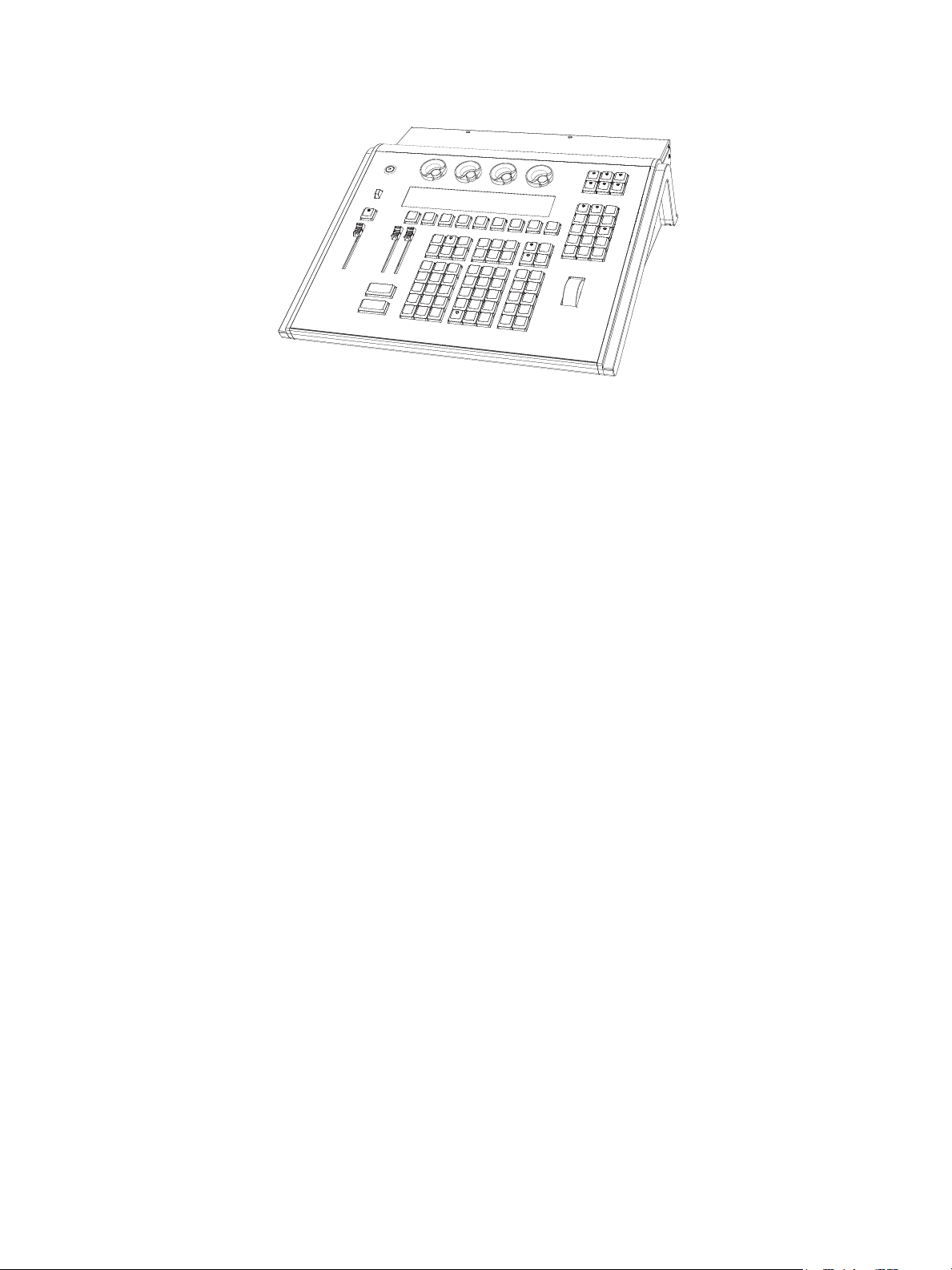
Console
Ion is designed from conception as a fully integrated controller for conventional lights and
multi-parameter devices (for example: moving lights, LEDs, color scrollers, gobo wheels). Attention
to detail across all areas of the system design and architecture allows you the utmost flexibility and
customization of use.
Ion allows designers and programmers to develop a mutual vocabulary for control. This
implementation of simple and uniform syntax for control provides a solid foundation for both
experienced and inexperienced users.
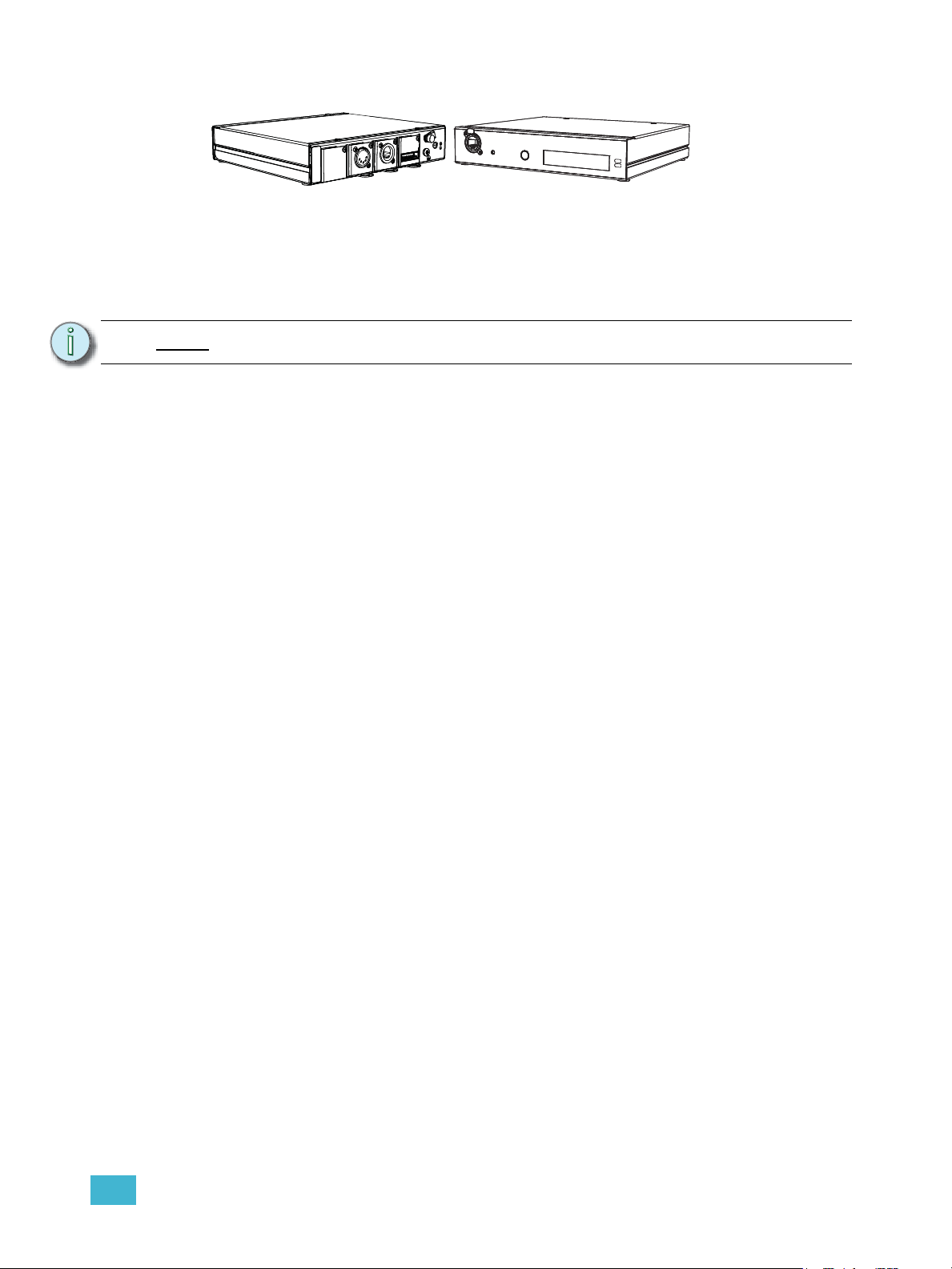
Remote Processor Unit (RPU)
The RPU can be used as the primary, backup processor for the system, a client, or for primary
playback in installations that do not require a facepanel after initial programming is completed.
For more information, see the appendix Remote Processor Unit (RPU), page 383.
Remote Video Interface (RVI)
The remote video interface allows remote interaction with the lighting control system. This can be
for display purposes only. Additionally, with a mouse and alphanumeric keyboard attached, the RVI
can be used as a remote programming station. The RVI provides supports for a maximum of two
DVI or SVGA monitors, 1280x1024 minimum resolution.
For more information, see the appendix Remote Video Interface (RVI), page 379.
Radio Focus Remote (RFR)
The RFR provides wireless control of key front panel functions.The base station for the RFR can be
networked into the system, or can connect to a console or remote device using the USB interface.
For more information, see the appendix Remote Control, page 377.
iRFR and aRFR
The iRFR and aRFR provide wireless control of key front panel functions.See “iRFR” on
page 388.See “aRFR” on page 388.
10 Ion Operations Manual
Page 27
Gateways
Ion is part of a fully networked system capable of direct output of both ETCNet2 and Net3.
Gateways can be configured to listen to either ETCNet2 or Net3 and provide interface to devices in
the lighting system that do not accept network communication directly. Gateways are provided for
DMX/RDM output, show control input and output and analog input and output.
• Net3 to DMX/RDM gateways are provided with a maximum of four outputs, which can be
male, female, or terminal strip.
Note:
• Show Control Gateway supports MIDI In/Thru and Out and SMPTE In.
• I/O Gateway supports 24 analog inputs, 16 SPDT contact closure outputs, and RS-232 serial
protocol.
Net3 Gateways only support RDM when in Net3 mode.
1 System Overview 11
Page 28
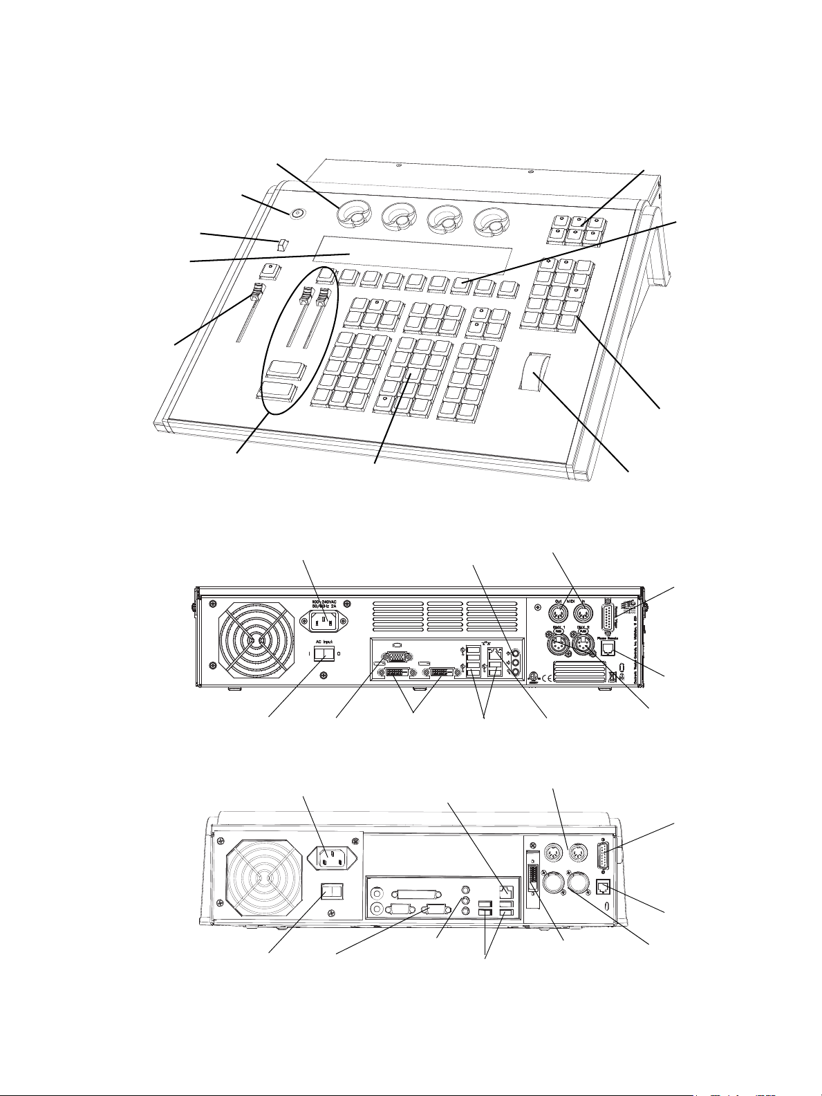
Console Geography
Parameter category/
encoder page buttons
Power button
USB port
Level
wheel
Navigation keys
Paged encoders
Control
keypad
Playback
controls
LCD screen
Blackout and
Grandmaster
Softkeys
VGA port
DVI video
ports
IEC receptacle
MIDI Out and In
Hard power switch
Ethernet
port
DMX ports
1 and 2
USB
ports
Remote
trigger
port
Phone
Remote
Port
Current Ion
Rear panel
Audio Ports
(not currently
supported)
VGA port
(blue)
Dual DVI video
port (white)
IEC receptacle
MIDI Out and In
Hard power switch
Ethernet
port
DMX ports
1 and 2
USB
ports
Remote
trigger
port
Phone
Remote
Port
Original Ion
Rear panel
Audio Ports
(not currently
supported)
Below is a diagram of the Ion console with references made to specific areas of use. The terms and
names for each area and interface are used throughout this manual.
12 Ion Operations Manual
Page 29
Terminology
Power Button
The power button on the front of the console is used to power up or power down. A separate power
switch, located in the rear panel, can be used to disconnect power from the console’s internal
components.
WARNING:
Before servicing Ion, you must switch off the power on the rear panel and
disconnect the power cord completely.
USB Ports
One USB port is provided on the front of the console to connect any USB storage device. An
additional USB ports on the rear panel can be used to connect peripherals such as an
alphanumeric keyboard, pointing device, or touchscreen control for external monitors.
.
CAUTION:
The USB ports cannot be used for charging devices such as cell phones.
Encoders
Encoders and the LCD (see below) for control of non-intensity parameters are provided at the top
center of the console. The four encoders are pageable controls, which are populated on the LCD
with the parameters used in your show.
LCD
This display accompanies the CIA as an additional user interface. This LCD offers you softkeys,
encoder information, and an additional view of the command line.
Load
The load button is located above the fader pair at the bottom of the LCD and is used to load the
specified cue.
Control Keypad
The control keypad area is divided into three general sections including record targets, numeric
keypad and modifiers, and special function controls.
Level Wheel
Adjusts intensity for selected channels. It also provides scrolling and zoom functions in various
modes.
Navigation Keypad
Used for quick access to the live and blind displays, format, paging, and navigation within displays.
Parameter Category/ Encoder Page Buttons
Parameter buttons are used to select parameter categories and change encoder pages. To post a
parameter category to the command line, use [Shift] & [Encoder Page Button].
IEEE Ethernet 802.3 Ethernet Port
Ethernet port for connection to a network switch, network gateways, and accessory devices.
1 System Overview 13
Page 30
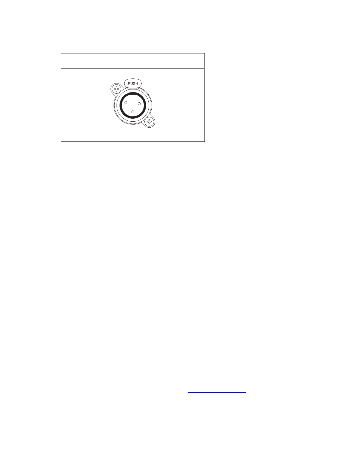
Littlites
Littlite XLR 3-Pin Female Connector
1
2
3
®
You may connect a Littlite to the side of your Ion console.
Dimming Littlites
Attached desk lamps can be dimmed either with the desk lamp control knob on the side of the
console, or from the software.
Desk lamp controls are found in Setup>Desk>Brightness Settings. The {Desk Lamp} slider has
a range of 0% (dimmest) to 100% (brightest). The default setting is 0%. The console will set the
desk lamp to this setting on startup of the application. See “{Brightness Settings}” on page 108.
The desk lamps can also be controlled by holding down [Displays] and rolling the level wheel.
Cleaning Ion
Should the exterior or LCD of your Ion require cleaning, you may gently wipe them with a
dampened (not dripping
If this does not clean the console sufficiently, you may apply some window cleaner (containing
ammonia is fine) to the cloth and repeat the process until clean.
Outputting DMX
In order to output levels from Ion, you can either use the DMX ports on the back of the console, or
to output over a network, you may connect a Net3 gateway or Net2 node. If your devices receive
Net3 or ETCNet2 directly, no gateway or node is required.
Ion has two DMX ports. To output, connect one 5 pin XLR cable per port. The first port will default
to outputting the first universe of DMX, addresses 1-512, and the second port to the second
universe, outputting addresses 513-1024. See Local DMX Outputs, page 351 for information on
reconfiguring the DMX ports.
Nodes and gateways will function with Ion out of the box without previous configuration. However if
custom configuration is required, you will need to use either NCE (Network Configuration Editor) or
GCE (Gateway Configuration Editor). GCE is installed on Ion by default and can be accessed in
ECU>Settings>Maintenance>Gateway Configuration Editor (GCE). NCE can be installed on
the console or a Windows
For more information on Net3 gateways or Net2 nodes, see the product literature that accompanied
the hardware or download it from our website at www.etcconnect.com.
), non-abrasive paper towel or soft cloth.
®
PC for configuration.
14 Ion Operations Manual
Page 31

Console Capacities
Output Parameters
• 1,024 outputs (DMX channels)
-or-
• 1,536 outputs (DMX channels)
-or-
• 2,048 outputs (DMX channels)
-or-
• 3,072 outputs (DMX channels)
Channel Counts
• 10,000 channels (any number from 1 to 99,999)
Cues and Cue Lists
• Up to 999 cue lists
• Up to 10,000 cues
Record Targets
• 1,000 Groups
• 1,000 x 4 Palettes (Intensity, Focus, Color and Beam)
• 1,000 Presets
• 1,000 Effects
• 1,000 Macros
Faders
• 1 dedicated Master Playback, with Go and Stop/Back
• a maximum of 200 configurable playbacks, with Go and Stop/Back
• a maximum of 300 configurable submasters, with Bump and Assert/Select
1 System Overview 15
Page 32

16 Ion Operations Manual
Page 33

Chapter 2
System Basics
This chapter explains the base level procedures for setting up, navigating, and understanding how
to operate Ion.
This chapter contains the following sections:
• Setting Up the Hardware . . . . . . . . . . . . . . . . . . . . . . . . . . . . .18
• Power . . . . . . . . . . . . . . . . . . . . . . . . . . . . . . . . . . . . . . . . . . . .19
• Your First Interaction. . . . . . . . . . . . . . . . . . . . . . . . . . . . . . . .20
• The Central Information Area (CIA) . . . . . . . . . . . . . . . . . . . .22
• Using the Browser . . . . . . . . . . . . . . . . . . . . . . . . . . . . . . . . . .24
• Display Control and Navigation . . . . . . . . . . . . . . . . . . . . . . .28
• Graphical User Interface (GUI) Display Conventions. . . . . .31
• Using [Format] . . . . . . . . . . . . . . . . . . . . . . . . . . . . . . . . . . . . .39
• Using Flexichannel . . . . . . . . . . . . . . . . . . . . . . . . . . . . . . . . .36
• Encoders . . . . . . . . . . . . . . . . . . . . . . . . . . . . . . . . . . . . . . . . .45
• Moving Light Controls. . . . . . . . . . . . . . . . . . . . . . . . . . . . . . .46
• Using Softkeys. . . . . . . . . . . . . . . . . . . . . . . . . . . . . . . . . . . . .47
2 System Basics 17
Page 34

Setting Up the Hardware
Follow these steps to prepare your Ion for use.
Step 1: Place your console on a firm, level surface. Be sure to leave space for access to the
rear of the console. You will need to connect several items to the ports on the back.
Step 2: Connect any monitors to the proper ports on the back of the console.
Note:
Step 3: Connect the keyboard and mouse. Attach to the appropriate connector on the back of
Step 4: If you will be connecting to an Eos Family network, connect the appropriate Ethernet
Step 5: If you plan on using the DMX ports on the back of Ion to control your lighting system,
Step 6: Attach the appropriate IEC power cable for your location to the IEC connector on the
Your console hardware is now ready to be powered up.
Ion supports up to 2 monitors, either 2 DVI -D monitors or 1 DVI-D and 1 VGA.
the console.
(CAT 5 or better) cable to the Ethernet port on the back of the console.
attach the appropriate DMX connector and cable to the desired port. These ports
default to output DMX universes one and two. Configuration is required to use any
other universe. For more information, see Local DMX Outputs, page 351 in the ECU
appendix.
back of the console, just above the power switch.
18 Ion Operations Manual
Page 35

Power
Power Up the Console
Step 1: Attach the appropriate power cable to the IEC connector on the rear of the console.
Step 2: Press the I/O switch (I is “on”) next to the IEC connector on the rear of the console to
turn power on. This will provide power to all internal electronics.
Note:
Step 3: Press the power button, located in the top left corner of the console, above the USB
Note:
You need to wait about 30 seconds between steps 2 and 3.
port. The button LED will illuminate blue to indicate the console is running. The
console will boot up into the Ion environment. The Ion system is now ready for use.
In the future, you may go straight to the welcome screen by adjusting a setting in
the ECU. See Open in Shell, page 337 in the ECU appendix.
Power Down the Console
Step 1: After saving your show (see below), in the browser menu select Power Off Device.
A dialogue box opens asking you to confirm.
Step 2: Confirm this command by clicking {OK} in the dialog box. The console will power
down.
-Or-
Step 1: Press the power button, located on the face panel. A dialogue box opens asking you
to confirm.
Step 2: Confirm this command by pressing {OK} in the dialog box or by pressing the power
button again. The console will power down.
Note:
Ion is a persistent storage console. Therefore if you shut down your system
without saving the show file, you will return to the same place in your show when
you reboot.
Note:
The console will display an improper shutdown message on the next power up if
the console was not powered down from the browser menu or welcome screen.
2 System Basics 19
Page 36
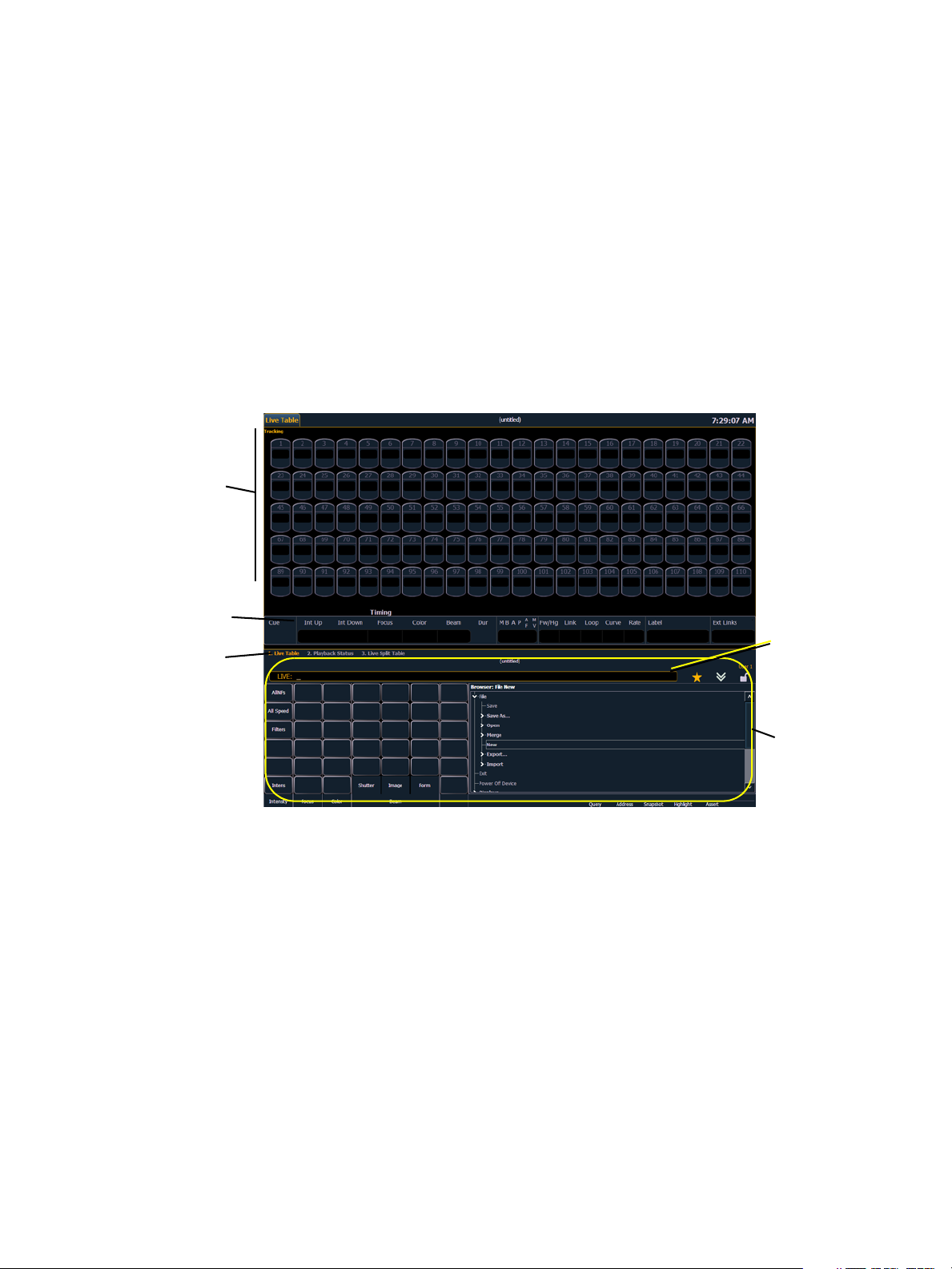
Your First Interaction
Initial View - Primary/CIA
Primary screen live display
CIA
Playback
Status Display
Command
line
Tabs
When you first start up Ion, you will immediately enter the Ion software environment.
Since Ion can be set up with one or two monitors, what you will first see depends partly upon the
number of monitors you are using.
Single Monitor Configuration
When using a single monitor, the top half of the initial display screen becomes the primary viewing
area for displayed information. Ion will first open with the live table display on the top (primary) half
of the screen and the CIA on the bottom half of the screen.
When the CIA is open, one line of the playback status display is visible above the double arrows.
You can view more of the playback status display by collapsing the CIA (see Collapse/Expand the
CIA, page 22).
20 Ion Operations Manual
Page 37
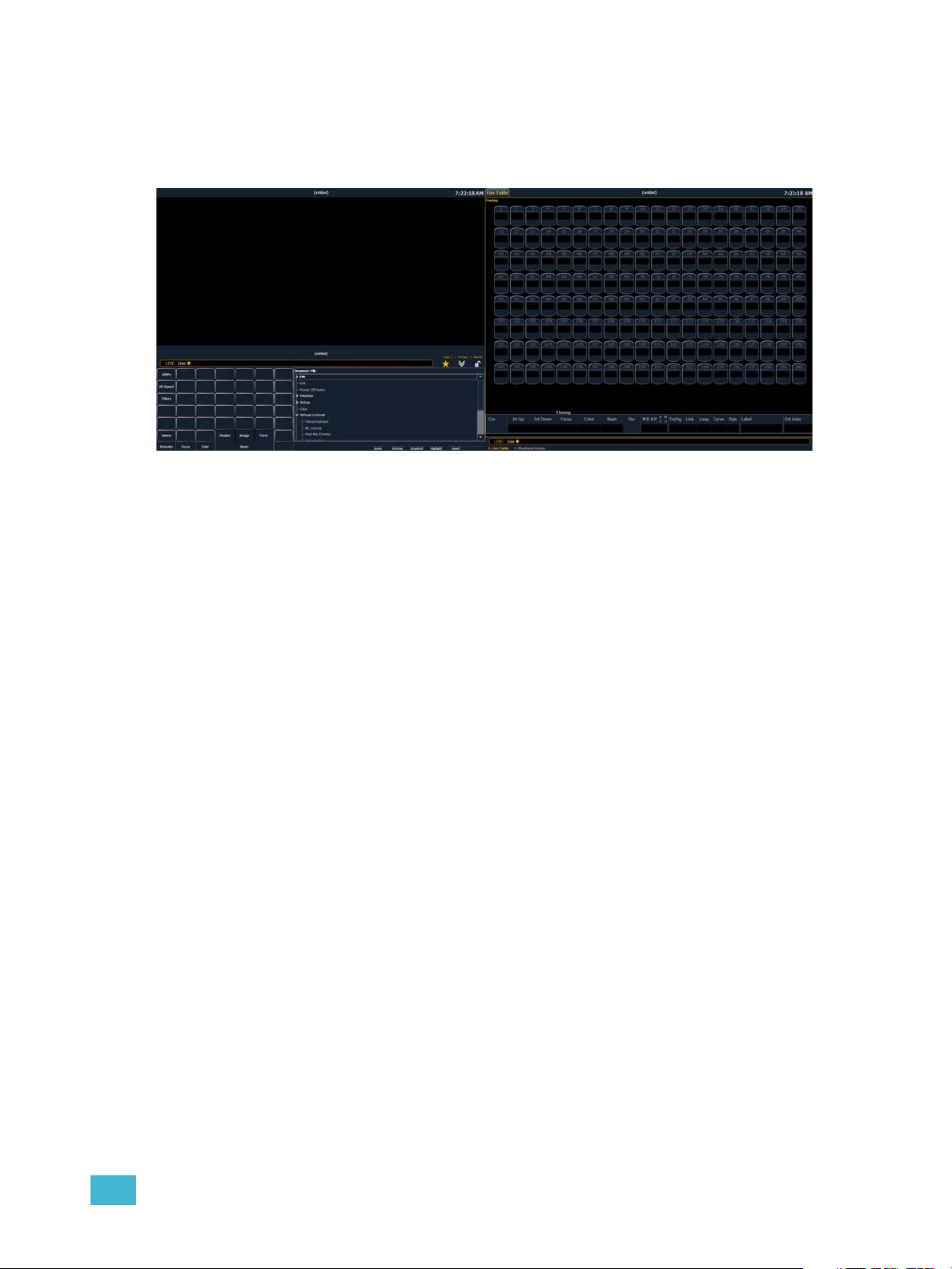
Dual Monitor Configuration
When two monitors are used, one monitor will default to showing the CIA, and the other will default
to having the live display and the playback status display open on tabs.
For additional information on displays, see Display Control and Navigation, page 28.
Please see Monitor Arrangement, page 338 for more information on configuring Ion for a dual
monitor configuration.
2 System Basics 21
Page 38
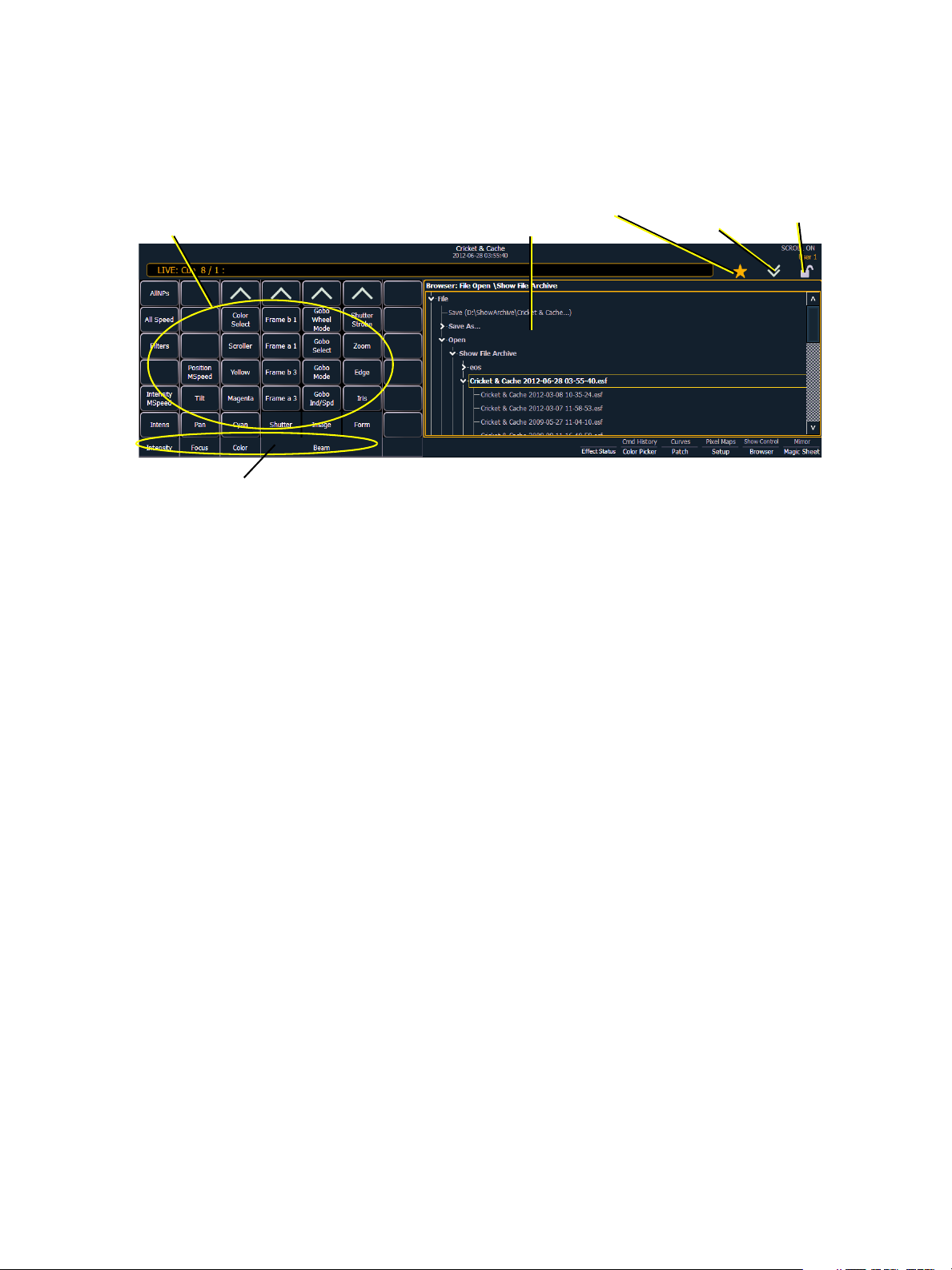
The Central Information Area (CIA)
Parameter category button labels
Browser
Parameter display
Double
arrows
CIA lock
Favorite star
The Central Information Area (CIA) is displayed on the lower portion of the screen. By default, the
CIA consists of two primary areas: the parameter display and the browser.
Parameter Display
This display shows the parameters available for patched channels. It is also where you can select
which parameters to view in live or blind, or select parameters for command line control. The
parameter display will dynamically change depending on the channel (fixture) selected and its
applicable parameters.
Browser
The browser is the interface for numerous functions including saving a show, opening a show,
changing settings, viewing record target lists, opening displays and many other functions.
Collapse/Expand the CIA
It is possible to collapse the CIA from view. To do this, you can click the double arrow icon centered
above the CIA. The CIA will collapse from view, exposing a larger viewing area of whatever display
is visible above the CIA. The double arrows will move to the bottom of the screen.
To expand the CIA into view again, click the double arrow at the bottom of the screen. The CIA will
reopen.
22 Ion Operations Manual
Page 39

Lock the CIA
You can lock the CIA in place to prevent it from being collapsed.
To lock the CIA, click on the lock above the browser. The double arrow above the CIA will
disappear and the lock will “lock”.
To unlock the CIA, click the sunken lock again and the double arrows will reappear.
Favorite CIA Display
You can select a favorite default display for the CIA that will
show when [Displays] is pressed. The standard default display for the CIA is the Browser.
The favorite display will show a gold star icon at the top of the CIA by the double arrows & lock.
Displays that can be selected as a favorite, but are currently not, will show a grey star at the top of
the CIA. Click on the grey star to make that display your favorite. That display will now be the new
default display for the CIA. Displays that show up in the CIA but can not be the default display will
not show the star icon.
The following displays can be set as the favorite CIA default:
• About
• Browser (default)
• Color Picker
• Direct Selects
• Virtual Sliders
•Virtual Keypad
• ML Controls
• Encoder Information Screen
• Effects Status
Locking the Facepanel
It is possible to lock out the facepanel, which prevents any actions from the command line or CIA.
To lock out the facepanel, press [Shift] & [Escape]. To unlock the facepanel, press [Shift] &
[Escape] again.
Note:
This will also lock any fader wings or USB connected peripherals.
2 System Basics 23
Page 40
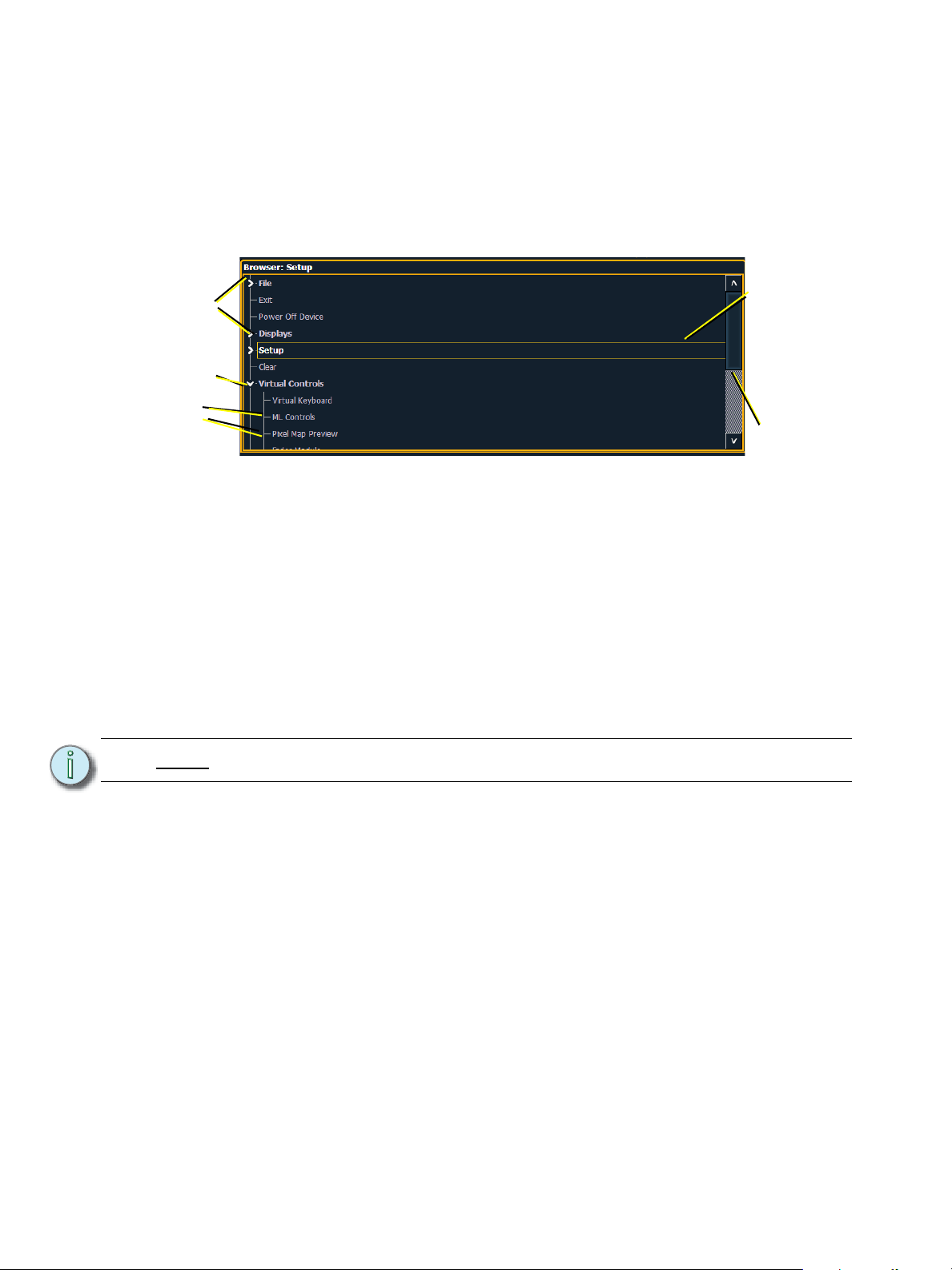
Using the Browser
Menu arrows
Opened menu
Sub menus
Scroll bar
Selection bar
To use the browser, you must first draw focus to it by clicking anywhere in the browser area of the
CIA or by pressing the [Displays] key. If the browser is not visible, double pressing
[Displays]>Browser will always bring up the browser.
When focus is on the browser, the window border highlights in gold. The scroll lock LED illuminates
red and the paging keys will now control selection in the browser.
• Use the page arrow keys to move the selection bar up and down the list. You can also use the
level wheel to scroll through the list.
• When the bar highlights the desired menu, press [Page
• Continue pressing [Page
• Scroll to the item you wish to open using [Page
may also click the item you wish to open and then press [Select]. You can also use the level
wheel to scroll in the browser.
• If you wish to close a submenu scroll to that item and press [Page
• To draw focus to the CIA press the [Displays] key.
• Additional presses of [Displays] will minimize or restore the CIA.
Note:
The [Select] key can be used to confirm a choice in the browser.
] to open submenus.
] or [Page ] and then press [Select]. You
] to open the menu.
].
Virtual Keyboard
It is possible to open a virtual keyboard in the CIA which mimics the hard keys found on the actual
Eos keypad. The keypad will not match the facepanel on Ion. This virtual keyboard is accessible
from the browser.
To open the Virtual Keyboard on a monitor:
Step 1: Go to Browser>Virtual Controls>Virtual Keyboard. A window will open in the CIA
displaying your monitor placement options for the keyboard.
Step 2: Click the placement option in which you want the keyboard to appear.
To close the Virtual Keyboard on a monitor:
Step 1: Go to Browser>Virtual Controls>Close Module. The placement screen will appear
again in the CIA.
Step 2: Click the placement of the module you wish to close. The module will be removed.
24 Ion Operations Manual
Page 41

Fader Module
If you prefer to have faders available to you, the monitors can be populated with virtual faders,
called fader modules.
To open the fader module on a monitor:
Step 1: Go to Browser>Virtual Controls>Fader Module. A window will open in the CIA
displaying your monitor placement options for the module.
Step 2: Click the placement option in the CIA in which you want the module to appear.
To close the fader module on a monitor:
Step 1: Go to Browser>Virtual Controls>Close Module. The placement screen will appear
again in the CIA.
Step 2: Click the placement of the module you wish to close. The module will be removed.
Using Direct Selects
Direct selects allow access to a number of controls, including a channel select display. If there are
more items than can be viewed at once, you may view subsequent pages by using the page buttons
({Page
Selecting Channels with Direct Selects
Channel direct selects are highlighted when selected. Channel selection is generally an additive
process, if channels 1-5 are selected, pressing {Channel 6} adds channel 6 to the selection,
leaving channels 1-5 also selected. Pressing {Channel 6} again will deselect the channel.
}, {Page }) by the direct selects.
If you have labeled channels in patch, those labels will be displayed above the channel number
when viewing channels in the direct selects.
It is possible to double hit a channel button. This selects that channel and deselects any previously
selected channels.
• {Channel 1} - adds channel 1 to currently selected channels, if not currently selected.
• {Channel 1} {Channel 10} - adds channels 1 and 10 to currently selected channels.
• {Channel 1} {Channel 1} - selects channel 1, deselects all other channels.
• {Page
• {Page
} - pages direct selects down by one page.
} - pages direct selects up by one page.
Direct Selects
Ion gives you the option of opening direct select modules on the monitors.
To open the direct selects on a monitor:
Step 1: Go to Browser>Virtual Controls>5 x 10 Direct Select Module. A window will open
in the CIA displaying your monitor placement options for the module.
Step 2: Click the placement option in which you want the module to appear.
To close the direct selects on a monitor:
Step 1: Go to Browser>Virtual Controls>Close Module. The placement screen will appear
again in the CIA.
Step 2: Click the placement of the module you wish to close. The module will be removed.
For information on populating direct selects see Organizing the Direct Selects.
2 System Basics 25
Page 42
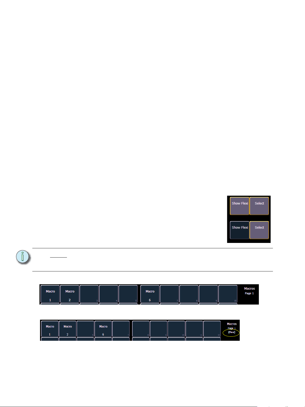
Organizing the Direct Selects
On
Off
Show Flexi is Off
Show Flexi is On
You have considerable flexibility in how you organize the direct selects. They may be arranged to
display one of several different types of data.
To choose which information to view:
Step 1: Click the {Select} button for any block of direct selects. You will be offered the
following choices to view: Channels, Groups, Intensity Palettes, Focus Palettes,
Color Palettes, Beam Palettes, Presets, Macros, Effects, and Snapshot.
Step 2: Click the button for the data you wish to view and the associated direct selects will
populate with any recorded information of that type. If there is no recorded information
of that type the block of buttons will remain empty but will populate with data of that
type as associated record targets are stored.
Step 3: You may also click {Select} again, without choosing any option, to return to the
previous state.
You can increase/decrease the size of any set of direct selects by pressing the {20/50} button,
which will change the display between one set of 50 buttons and two sets of 20 buttons. Or you may
press the {100} button to expand to a full set of 100 buttons. Press {100} again to switch back to the
previous view.
You may also press the {Expand} button (located beneath the {Select} button) to expand a set of
direct selects to full screen. Press {Expand} again to return the set to its previous size and
mapping. Century and Millennium buttons will display when direct selects are in expand mode.
When the direct selects are opened on a tab, two sets of direct selects will be displayed.
Direct Selects in Flexi Mode
Direct selects can be placed into a flexi mode, which will remove
empty tiles. When {Select} is pressed, the {Show Flexi} button
will display.
Note:
A single empty direct select tile may remain if the adjacent direct select tiles are
not sequential. This is to allow an easy way to insert a new direct select between
the existing ones.
.
26 Ion Operations Manual
Page 43
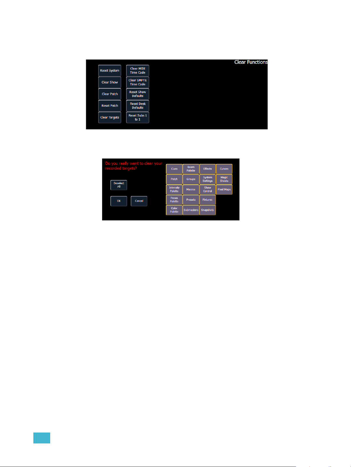
Clear Functions
You can access the various clear options from the browser by selecting {Clear} from the main
browser menu. The clear functions window will open in the CIA.
From this menu you can select one of the available clear options by clicking on the desired button
in the CIA. Ion will ask you for a confirmation before performing the selected clear. For {Clear
Targets}, Ion will allow you to choose which record targets you want to clear.
From the {Clear Targets} screen you can select which record targets you wish to clear. The buttons
at the center of the CIA represent all of the record targets that you can choose to clear. By default
all components are selected (gray) and will be cleared. To withhold any targets from being cleared,
simply deselect them in the CIA by clicking the respective button.
To reselect all targets, click the {Reset} button and all buttons will return to gray (selected). To stop
the process, click the {Cancel} button.
When you have selected or deselected all of the record targets you require, click {OK}.
After clearing, the CIA will return to the browser. If you want to perform additional clear functions,
you must select {Clear} from the browser again.
To exit the clear functions screen without clearing, press the [Displays] key at any time or select a
clear button and then select {Cancel} from the confirmation screen.
Reset System vs Clear Show
Using {Reset System} will open a new show file and reset the Setup options to their defaults. Using
{Clear Show} will only open a new show file.
Reset Patch vs Clear Patch
Using {Reset Patch} will clear your patch and set it to a 1-to-1 patch. Using {Clear Patch} will only
clear out the patch.
2 System Basics 27
Page 44

Display Control and Navigation
Opening and Closing Displays
The live/ blind display will always open as tab 1. The playback status display will always open as tab
2. Neither of these displays can be closed.
Other displays are numbered as they are opened. Tab numbering is useful for navigating to views.
Displays can be opened and closed in different ways, depending on the display. Many displays are
accessible from the browser, while other displays are accessible from the LCD softkeys. The blind
displays of record targets (also called “lists”) can be quickly accessed by double pressing the record
target button (for example, [Preset] [Preset] opens the preset list).
From the browser
Open and navigate the browser as described in Using the Browser, page 24. When you open a new
display (such as the cue list index, group list, or patch) and it is posted in a tab view, it will open on
monitor 2. If the display does not open as a tab view (such as “setup” or the browser) it will open in
the CIA.
Again, any time you wish to return to the browser, simply press [Displays] and then {Browser} and
it will be made available.
From the hardkeys
You can open list views of any record target by double-pressing the key for the desired record
target.
From the LCD softkeys
To open any displays accessible from the softkeys, press [Displays]. The softkeys will repaint to
display:
• Effect Status
• Color Picker
•Patch
• Setup
•Browser
•Magic Sheet
• Command History
•Curves
•Pixel Maps
• Show Control
•Mirror
Any of these softkeys will open the associated display with a single press.
Closing Displays
To close any tab display, select the display by using the [Tab] key or other means of navigation.
When the desired display is active, press [Escape] to close it.
To close a display in the CIA, press the [Display] key and the browser will reappear.
To close all displays except for the live/blind display and the playback status display (tabs 1 and 2),
press [Shift] & [Tab].
28 Ion Operations Manual
Page 45

Selecting Displays
When a display is selected, the screen is highlighted in a gold border and the display name (such
as “1. Live Channel”) will be in gold as well. When a display is not selected, there is no border and
the tab name is gray.
If a display is already open, it can be selected in the following ways:
•Press [Tab] to change focus from the currently selected tab to the tab immediately to the right.
If no tabs are to the right, the selection moves to the first tab on the left of all available monitors.
• Press [Tab] & [n], where “n” represents the tab number of the desired tab.
• Press [Live] or [Blind] to automatically bring live/blind into focus. If there are multiple
instances of live/blind, pressing [Shift] + [Live] / [Blind] brings the next live/blind tab into
focus.
• Double press a record target button (such as [Preset] or [Submaster]) to either open the
associated display or select it if it is already open.
Moving Displays
To move the active display from one monitor to another, press and hold the [Tab] key and use the
page arrow keys to move the display in the direction of the desired screen. One press of the left or
right page keys will move the display to the next screen in that direction. To move it back, press the
opposite arrow key.
Scrolling within a Display
By default the page keys will advance/retreat a display by one page per press. However, to scroll
through displays you may press the [Scroll Lock] key on the keypad. The LED on the button
illuminates red when in scroll lock mode.
Scroll lock is a toggle state. When scroll lock is first pressed:
• [Page
• [Page
• [Page
• [Page
] - scrolls table, spreadsheet and channel views down,
] - scrolls table, spreadsheet and channel views up,
] - scrolls table and spreadsheet views right,
] - scrolls table and spreadsheet views left.
2 System Basics 29
Page 46

Expanding Displays
[Expand] allows a tab to be viewed across multiple external monitors.
To expand a display to an adjacent monitor, press [Expand] & [Page
[Expand] & [Page
To collapse an expanded view, press [Expand] & [Page
] if in either view.
] if in table views or [Expand] & [Page
] if in table views or
] if in summary views.
Note:
Please note that you must have two monitors attached to Ion to use the [Expand]
feature.
If the display you are expanding is at the right most position, the display will
expand onto the first (or left most) monitor.
Zooming Displays
You may zoom in and out on displays. To do this, press and hold the [Format] button and scroll the
Level Wheel to alter the display. Scrolling the wheel up zooms in. Scrolling the wheel down zooms
out. Zooming the channel summary display when it is in 100 channel mode is not supported. You
can also zoom by holding down the left mouse button and rolling the scroll wheel on a mouse.
30 Ion Operations Manual
Page 47
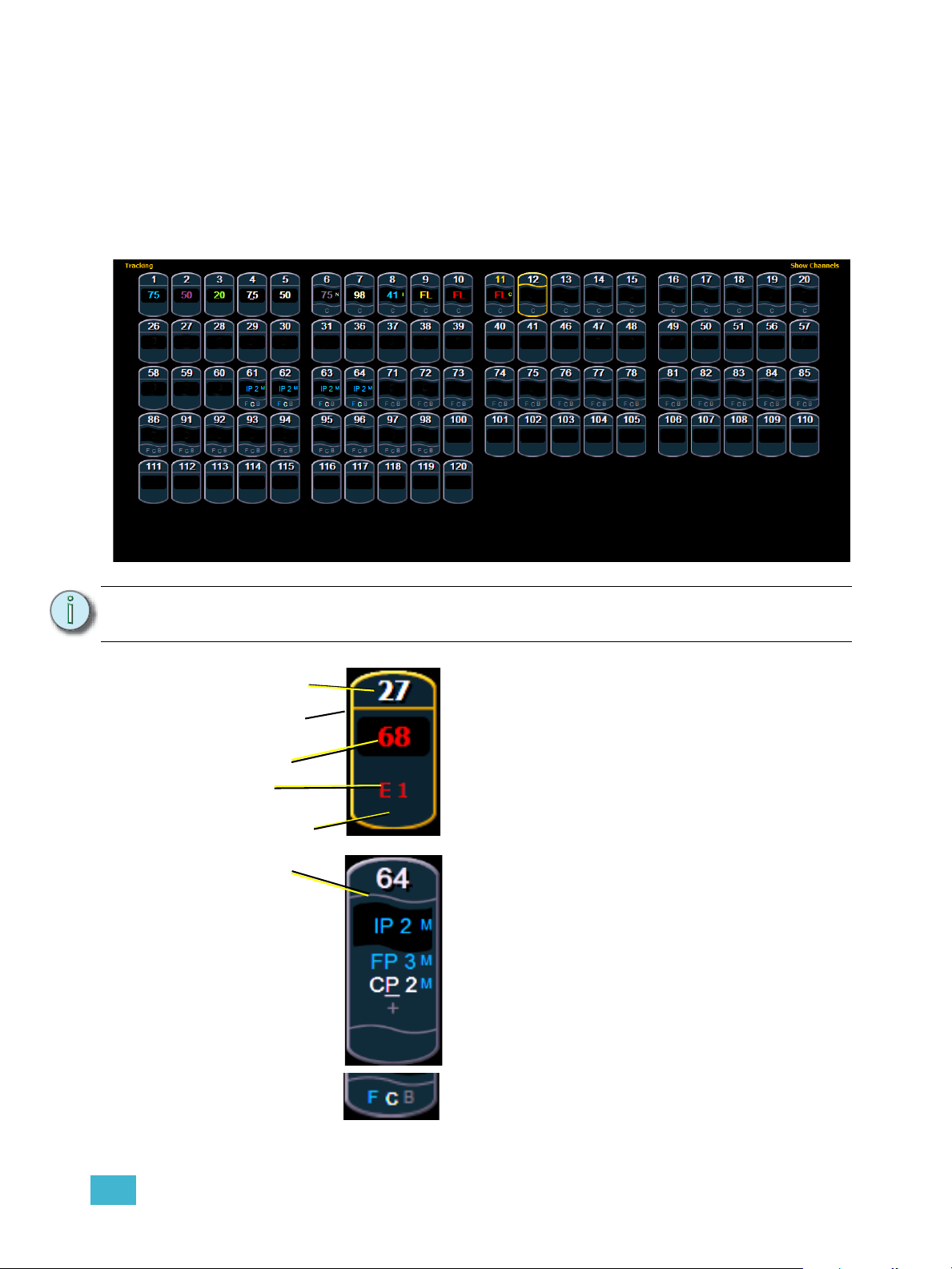
Graphical User Interface (GUI) Display Conventions
Channel Number
Straight line under
channel heading
Intensity data (I)
No other parameter
categories
Effect data
Wavy line under
channel heading
Intensity data (I)
Focus data (F)
Color data (C)
Beam data (B)
F, C, B icons
when collapsed
Ion relies on many traditional ETC indicators which you may be familiar with, as well as some new
ones. This section identifies the graphical and colorful conventions used in Ion to indicate
conditions to you.
Indicators in the Live/Blind Display
This is the live/blind summary view.
2 System Basics 31
Note: The color and text conventions described below apply regardless of the format of
live/blind being used (see Using [Format], page 39).
Conventionals
Most of the channels in the above image are conventional
channels (intensity is the only available parameter).
Conventionals have a straight line beneath the channel
number. They also display only the top field, intensity, as
no other parameters are available on a conventional
channel.
Moving Lights or Multi-parameter Devices
Several channels in the image are moving lights
(possessing more parameters than just intensity).
Moving light channels have a wavy line beneath the
channel number as well as parameter category indicators
at the bottom of the channel.
This view also has additional data fields beneath intensity
(F, C, B). This information can be suppressed by pressing
and holding [Data] and any of the encoder paging keys
(Focus, Color, Image, Shutter, or Form). Doing so will
leave only the intensity field and FCB indicators at the
bottom of the channel.
Page 48
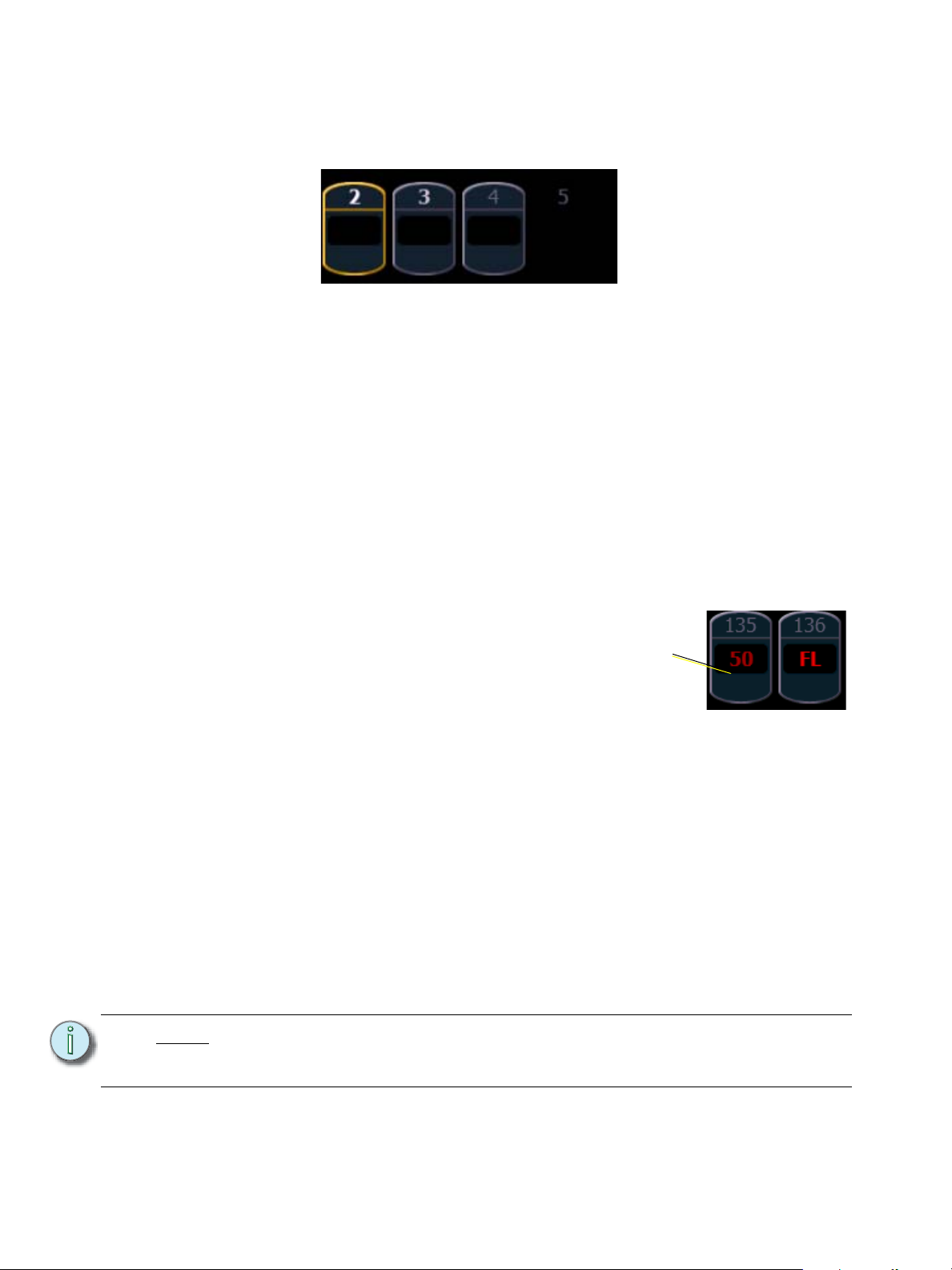
Color indicators
Unselected
Selected
Unpatched
Deleted
Different
User ID
Ion uses color to indicate the selection state and information about channel or parameter levels.
Channel numbers/channel headers
• Gray number . . . . . . . . . Unpatched channel number.
• White number . . . . . . . .Selected channel number.
• Bright White number . .Channel is parked.
• Gold number . . . . . . . . .Channel is captured.
• Gold outline . . . . . . . . .Selected channel.
• Number with no graphicDeleted channel.
Channel or parameter levels
• Bright Red . . . . . . . . . . .Manual Data (any data that has been set but not yet stored to
an active cue or submaster) on all consoles using the same
user ID.
Note:
• Dark Red . . . . . . . . . . . .Manual Data (any data
that has been set but not
yet stored to an active cue
or submaster) from other
consoles that are using
different user IDs.
• Blue . . . . . . . . . . . . . . . .The intensity value is higher than in the previous cue.
Non-intensity parameters (NPs) are in blue when any move
instruction has occurred. Unmarked.
• Green . . . . . . . . . . . . . . .The intensity value is lower than in the previous cue.
Also used in reference marking to indicate a channel is
marked.
• Magenta. . . . . . . . . . . . .Value is unchanged from the previous cue (tracked).
• White . . . . . . . . . . . . . . .The value is blocked.
• White with an underscore Value is auto-blocked.
• Gray . . . . . . . . . . . . . . . . Default or the value is a null value (from either {Make Null}
or a filter). When nulled, a gray “n” appears next to the value.
• Yellow . . . . . . . . . . . . . .Data set from a submaster.
When data is in transition (moving), it will appear in a lighter version of its color.
This includes up/down fades for intensity, non-intensity moves from cues,
submaster, and timed manual changes.
32 Ion Operations Manual
Page 49
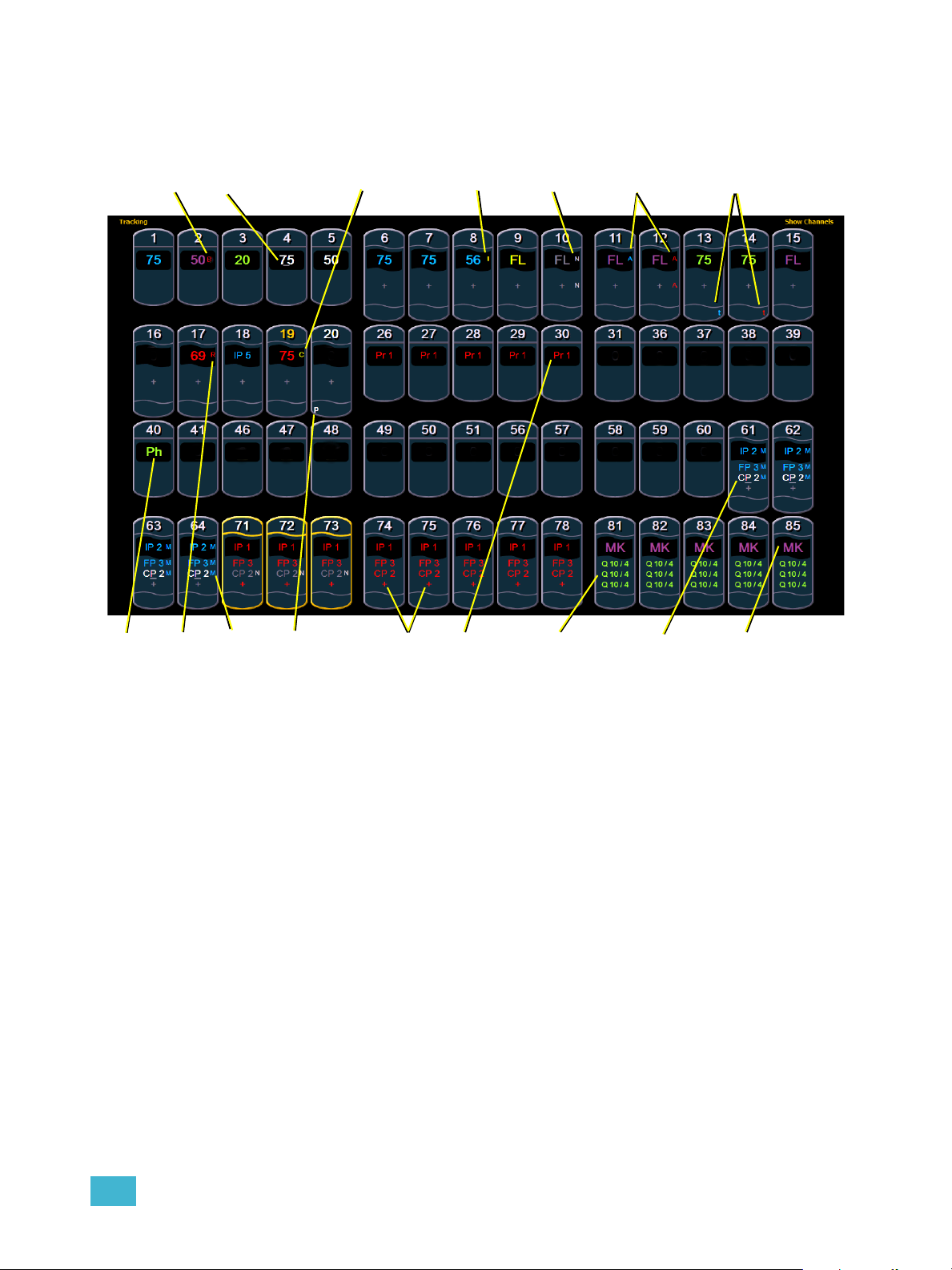
Text Indicators in live/blind
“B”
“N”
“_” (underscore)
“t”
“A”
“+”“R” “CP2”“Q 10/4”
“C”
“I”
“Ph” “P”
“MK”
“Pr”
“M”
Please note examples of text indicators in the following graphic:
Color conventions listed above apply to text indicators as well. Therefore red indicates a manual
value that must be stored.
Color conventions listed above apply to text indicators as well. Therefore red indicates a manual
value that must be stored.
• _ . . . . . . . . . . . . . . . . . . . Underlined value (white) indicates a system-applied block
• A. . . . . . . . . . . . . . . . . . . Indicates the channel or parameter is asserted.
• B. . . . . . . . . . . . . . . . . . .Indicates the channel or parameter is manually blocked. This
• C. . . . . . . . . . . . . . . . . . . Captured Channel
• I . . . . . . . . . . . . . . . . . . . Channel is controlled by an inhibitive submaster or
• IP, CP, FP, BP . . . . . . . .Indicates that the value is referenced to a palette (Intensity,
(also called an auto-block).
block must be stored.
grandmaster. When displayed in the Block flag, “I” indicates
a cue level intensity block.
Color, Focus, or Beam). This text is followed by a number,
indicating which palette is being referenced. This can be
substituted with the palette label if the “Show Reference
Label” setting is activated (see Show Reference Labels, page
107). Holding down [Shift] & [Label] will toggle between the
palette label and palette number.
2 System Basics 33
Page 50

• MK . . . . . . . . . . . . . . . . .Indicates the channel is marked for a later cue. The cue
number is indicated in the other categories (see “Q” below).
• N. . . . . . . . . . . . . . . . . . . Indicates the value is null (from either {Make Null} or a filter).
• P . . . . . . . . . . . . . . . . . . .Indicates the channel is parked.
• Ph. . . . . . . . . . . . . . . . . .Indicates the channel is at a preheat level.
• Pr . . . . . . . . . . . . . . . . . .Indicates that the value is referenced to a preset. This text is
followed by a number, indicating which preset is being
referenced. The preset label may also be shown if this setting
is enabled (see Show Reference Labels, page 107). Holding
down [Shift] & [Label] will toggle between the preset label
and preset number.
• Q. . . . . . . . . . . . . . . . . . .Found in the non-intensity categories of a marked channel.
The “Q” is followed by a number indicating which cue the
mark is in preparation for.
• t . . . . . . . . . . . . . . . . . . .The channel has discrete (parameter/category-specific)
timing.
• + . . . . . . . . . . . . . . . . . . .Found in place of parameter data in summary view. Indicates
that not all parameters in that category are at the same value.
This indicator is found only in the summary view or in table
views when the parameters are collapsed into a category
view.
• ! . . . . . . . . . . . . . . . . . . .Indicates an ACN, RDM, or dimmer error.
• ND . . . . . . . . . . . . . . . . .Indicates that a channel has been patched as a non-dim
fixture type.
• S . . . . . . . . . . . . . . . . . . .Indicates that a channel is stored to a shielded submaster.
• R. . . . . . . . . . . . . . . . . . . Indicates a manual reference override. Manual changes have
been made that override a previously stored reference (such
as to a palette or preset). Once recorded, the reference will
be broken. If updated, the referenced target will be updated
as well, unless otherwise instructed.
• M . . . . . . . . . . . . . . . . . . Indicates a mark is placed, but manual, and must be stored.
Is blue when stored.”m” indicates cue is not marking.
34 Ion Operations Manual
Page 51

[Data] Key
Pressing and holding [Data] allows you to view the values behind any referenced or marked data.
[Data] exposes the next lower reference level. So if you view a palette reference and press [Data],
the absolute data will be displayed instead. If you are viewing a preset, absolute or palette data will
be displayed, depending on what is contained in the preset.
The [Data] key is also used in combination with the encoder paging keys to change the level of
detail in summary and views, and to select parameters to view in spreadsheet modes.
[Time] Key
Pressing [Shift] & [Time] allows you to view discrete timing data behind any channel parameter.
Keep [Time] held down to page. [Time] exposes channel or parameter specific timing for any
channels in the current cue. The first value is the delay time. If “--” is displayed, there is no delay.
The value to the right of the / is the transition time.
When the [Time] button is pressed on a terminated command line, the selected cue is always
displayed for time modification. To add discrete timing to channels on a terminated command line,
those channels must be reselected.The [Select Last] command can be helpful.See “Select Last”
on page 123.
[Label] Key
Pressing and holding [Shift] & [Label] toggles the view to show reference labels or numbers
depending on what display setting is being used. See “Show Reference Labels” on page 107.
2 System Basics 35
Page 52

Using Flexichannel
Flexichannel (use of the [Flexi] key) allows you to view only channels meeting a certain criteria in
the live/blind display, therefore removing unwanted data from view. Flexichannel has several
available states which include allowing you to view:
• All channels
• All patched channels
• Manual channels
• All show channels (any channels that have data stored in a cue or submaster)
• Active channels (channels with intensity above zero or a move instruction)
• Selected channels
In flexi mode, any selected channels (including the last channel selection) are always included in
the view. Gaps in channel numbers are indicated by a vertical line between the channels where a
gap in numbering occurs.
To change flexi modes in the live/blind display, press [Flexi] to cycle through the views listed above.
When [Flexi] is held down, the softkeys change to represent all of the available flexi states. You can
select the desired flexi view from those keys.
[Next/Last] can be used to select the next or last channel in the current flexi mode.
[Thru] can be used to view only channels in the current flexi mode (except for selected channels
mode) as long as either the first or last channel in the [Thru] range is included in the current flexi
mode. To include channels not in the current flexi mode, [Thru] [Thru] can be used.
Flexichannel with Timing
You may also engage a “Channels with Timing” flexichannel state by pressing [Flexi] & [Time].
This will display all channels that have discrete timing in the current cue and will remove channels
without discrete timing from view.
You may still press [Shift] & [Time] to view the discrete time behind any parameter or category.
The display will remain in this state until you disengage it by pressing [Flexi] & [Time] again.
View Channels
You may select specific channels to appear in another flexichannel state called “View Channels”.
This state does not exist until you select channels to view. After view channels is activated, it will
appear in the rotation of flexichannel states when [Flexi] is pressed.
To select channels to view:
Step 1: Select channels on the command line (do not press [Enter]).
Step 2: Press and hold [Flexi].
Step 3: Press {View Chans}. The “View Channels” flexi state will be created and the
channels you selected will be visible in it.
The channels you selected will be visible in this flexi state until you select other channels and press
{View Chans} again. At any time, you can access the last channels you defined for this state by
pressing [Flexi] until this state is visible.
To redefine the selected channels in the state, simply follow the steps above again.
36 Ion Operations Manual
Page 53

Indicators in the Playback Status Display
Indicates the timing for a
category.
Indicates that timing has
been applied but there is
no move instruction.
If blank, default time is
used and there is no move
instruction
Sneak Counter
Color indicators
Text indicators
• Gold . . . . . . . . . . . . . . . .Any item (cue, list, page) highlighted in gold indicates
“current”.
Outlined in gold indicates “selected”.
• Red. . . . . . . . . . . . . . . . .Cue fade is in progress (cue list area)
• + (see cue 6) . . . . . . . . .Indicates that there is discrete timing within the associated
• * (see cue 4) . . . . . . . . . .Indicates the cue has an allfade command. Found in the cue
• - . . . . . . . . . . . . . . . . . . .Indicates a dark move, a cue that has any non-intensity
•x . . . . . . . . . . . . . . . . . . .Indicates that a mark has been placed, but the mark is
• A or a (see cues 3&4). . .Indicates an asserted cue. “A” indicates the entire cue is
• B or b (see cue 2&5) . . .Indicates a blocked cue. “B” indicates the entire cue is
cue. Found in the cue display “Timing” area.
display “Flags” area.
parameters moving on channels whose intensity is at 0.
broken.
asserted. “a” indicates a channel or parameter assert only.
Found in the cue display “Flags” area.
blocked. “b” indicates a channel/parameter block only. Found
in the cue display “Flags” area.
2 System Basics 37
• D. . . . . . . . . . . . . . . . . . . AutoMark is disabled.
Page 54

• F9 (see in cue 8) . . . . . . Indicates a follow time associated with the cue (in this case,
9 seconds). Found in the cue display.
• H4 (see in cue 6) . . . . . .Indicates a hang time associated with the cue (in this case 4
seconds). Found in the cue display.
• I . . . . . . . . . . . . . . . . . . . Indicates an intensity blocked cue. Found in the cue display
“Flags” area.
• M or m . . . . . . . . . . . . . .Indicates a marked cue. “M” indicates an AutoMark or a
reference mark that is used by a subsequent cue. “m”
indicates a reference mark that is currently unused by any
subsequent cue (see Using Mark, page 191). Found in the
“Flags” area.
• P (see in cue 3) . . . . . . .Indicates the cue will preheat. Found in the cue display
“Flags” area.
• R (see in cue 8) . . . . . . .Indicates the source cue which refers back to an earlier mark
(see Referenced Marks, page 193).
• E 1*(see in cue 2.5) . . . .Indicates a cue level effects override.
• M1 (see in cue 3) . . . . . .Indicates a linked macro.
• Q2/1 (see in cue 6). . . . .Indicates a linked cue.
• S1 (see in cue 1) . . . . . .Indicates a linked string.
.
Note:
For more details on information contained in the playback status display, see
Playback Status Display, page 42.
38 Ion Operations Manual
Page 55

Using [Format]
Channel numbers
Intensity data
F, C, B data
Summary View Collapsed
Some displays have multiple formats. When the display is first opened, it opens in its default view.
The default view for Live/Blind is table view, with all parameter categories displayed. When the
default format has been changed, those new settings will be used whenever the display is changed
back to that format.
Live and Blind share formatting. When you change from one format to another format, you are
always working with the same format until you change it. The exception to this is spreadsheet,
which is only available in blind. If you are working in blind spreadsheet, when you return to live you
will be working with the table or summary view, based on which one you were last using.
Summary View
The summary view displays the largest number of channels of any of the formats. Below you can
see channels 1-60 are shown. This format is best used to see large numbers of channels’ intensity
data and/or parameter category data. Individual parameters are not visible in this view.
FCB icons will appear at the bottom of the channel area for channels that have those parameters
patched to them.
To collapse the summary view, hold down the [Data] key and press any encoder paging key
(located to the right of the LCD).
When the summary view has been collapsed to show only intensity data, you may include focus,
color, or beam data in the summary view by holding down the [Data] key and pressing any encoder
paging key (located to the right of the LCD). This displays all categories.
2 System Basics 39
Page 56

Table View
Fixture types
Fixtures with only
type-specific
parameters displayed
Summarized category
Expanded category
Parameter data
Live Table View
Table view is available in live or blind. Unlike summary view, table view displays the fixture type
associated with channels and details about each channel’s category
In live, table view displays all active channel data being output from Ion. In blind, it will display all
data for a single record target (cue, preset, palette) depending on what is viewed. In table view,
focus, color, and beam information can be viewed in either a summary of these three categories.
To expand a category to show detail, press the [Data] key and the associated parameter key. For
example, [Data] & [Color] will change the color category from a summary view to a detailed one.
To collapse a category. press the [Data] key and the associated parameter key. You cannot hide a
category from view.
When a category has been expanded, to hide or reveal only certain parameters, press and hold
[Data] and then select the parameter buttons of the appropriate parameters in the CIA. The
parameters will be displayed or suppressed depending on the current view.
Notice that when you hold down the [Data] button, the buttons of parameters that are currently
selected for viewing will be highlighted in the CIA.
In the table view, a slight space is provided between fixture types, giving a clear delineation
between them. The name of the fixture type is displayed at the top of the section for that fixture.
Channels with only intensity parameters will display the same as in summary view.
or
parameter levels.
40 Ion Operations Manual
Page 57

Spreadsheet (Blind Only)
Channel number
Cue numbers
Parameters
Spreadsheet format is available only in blind mode. It is useful for viewing channel data and trends
for multiple cues, submasters, palettes, or presets at one time. Cues and other record targets are
displayed on the vertical axis and channel data is visible on the horizontal axis.
Since this is a blind-only view, changes made in this view are immediate and do not require a record
or update.
As with table view, spreadsheet format allows you to choose exactly which parameters you want to
view. Parameters can be expanded/suppressed by holding [Data] and pressing the desired
parameter buttons in the CIA. Category data is not available in spreadsheet, but you may hide all
parameters of a specific category by holding [Data] and pressing the desired parameter category
button (also called “encoder paging keys”). By default, the spreadsheet view displays just intensity.
2 System Basics 41
Page 58

Playback Status Display
Fader page
number
Fader numbers
Sneak Counter
The playback status display allows you to view a range of cues in the current cue list, all cue
attributes for those cues, and a view of the fader configurations for 10 pages of 10 faders each (for
a total of 100 visible faders.
Holding down [Time], while a cue is fading, will display the cue category times counting down in the
cue list display area. The default action is to show the total time not the countdown. To always show
the countdown, a {PSD Time Countdown} option is available in Setup, see {Displays}, page 107.
When the {PSD Time Countdown} is enabled, the cue category times will countdown as a cue is
fading. To see the total time, hold down the [Time] key. {PSD Time Countdown} is “disabled” by
default.
When focus is on the playback status display, you can use the paging keys to navigate in the
display. An optional command line for the playback status display is available. The optional
command line must be enabled to use. See “{Displays}” on page 107.
There are three formats for the playback status display. By default, it will be an expanded cue list
format. With the playback status display selected, press [Format] to toggle between the formats.
Expanded Cue List Format
Pressing [Format] with the playback status display active will access this format. In expanded cue
list, the view of the active cue list increases to the full size of the display. The current fader page is
still visible at the bottom of the screen.
42 Ion Operations Manual
Page 59

Split Playback Status Display
Optional
Command Line
Locked cue list
Unlocked cue list
Pressing [Format] with the playback status display active will access this format. With the playback
status display split, two different cue lists can be displayed at the same time by locking. If both cue
lists are unlocked, they will display the same list.
Note:
The first time you access the split playback status display, you may need to adjust
the splitter bar between the two lists to see the second list.
2 System Basics 43
Page 60

Fader Display Format
Current cue list
Cues
Timing data
Cue flags
Cue attributes
Fader Pages
1-10
Faders1-10
Master cue list timeline
Other cue list
Submasters
Pressing [Format] with the playback status display active will access this format.
44 Ion Operations Manual
Page 61

Encoders
The encoders are one of two ways to control the non-intensity parameters (NPs) of multipleparameter devices. The four encoders are identified by the encoder LCD, just beneath the
encoders.
Encoder Navigation
Use the encoder page buttons (located to the upper right of the encoder LCD) to choose which
parameters are currently available on the encoders. There are six readily usable buttons: [Focus],
[Color], [Custom], [Form], [Image], and [Shutter]. Pressing any of these will change the
parameters controlled by the encoders.
Some fixtures have more parameters than can be displayed on one encoder page. The number of
pages for each category is displayed at the right side of the encoder screen. To view the other
pages, simply press the [Color], [Custom], [Shutter], [Image], or [Form] button to advance the
pages, or press an encoder button with a number key to go directly to the page you want to access.
The number of pages is indicated in the LCD.
Encoders can be switched from course mode into fine by holding down [Shift] while using an
encoder will put it in fine mode for as long as [Shift] is held down. Once [Shift] is released, the
encoder will return to course mode.
Locking the Encoders
It is possible to lock out the encoders. To lock out the encoders, press [Escape] & [Encoder Page
Keys]. To unlock, press any of the [Encoder Page Keys].
Encoders in Blind
The encoders and level wheel are disabled by default when in the blind display. Pressing an
[Encoder Page Keys], for example [Color], will enable the encoders and level wheel. When the
encoders are disabled, trackball functionality for pan and tilt will also be disabled.
Flexi Encoders
Holding down [Flexi] and an [Encoder Page Keys], for example [Image], will put the encoders into
Flexi mode. In Flexi mode, any empty locations for parameters not applicable for selected channels
will be suppressed.
2 System Basics 45
Page 62

Moving Light Controls
1
2
3
4
5
6
7
8
9
10
11
12
An additional tool for controlling the non-intensity parameters (NPs) of multiple parameter devices
is the ML Controls. The ML Controls is found with the other virtual controls in the browser. Navigate
to Browser>Virtual Controls>ML Controls.
You will need to have a multi-parameter device selected to properly view this display. The display
will change based on the device selected. If you have a device that only has intensity and color
parameters, the ML Control display will only show intensity and color parameters.
ML Controls
Controls available in this display will change based on the fixture selected.
• 1 . . . . . . . . . . . . . . . . . . .Category button (Clicking this button will show or collapse the
encoder wheel, see #12)
• 2 . . . . . . . . . . . . . . . . . . .Parameter button (Clicking the button will put the parameter
on the command line.)
• 3 . . . . . . . . . . . . . . . . . . . Home button allows you to home a specific parameter or
attribute of a parameter.
• 4 . . . . . . . . . . . . . . . . . . .Parameter attributes
• 5 . . . . . . . . . . . . . . . . . . .Arrow to scroll through a fixture’s available categories.
• 6 . . . . . . . . . . . . . . . . . . .Palette button (Clicking the button will put the palette on the
command line.)
• 7 . . . . . . . . . . . . . . . . . . .Palette Select buttons. Will display number or label.
• 8 . . . . . . . . . . . . . . . . . . .Gives pan and tilt functionality to a mouse or trackball.
• 9 . . . . . . . . . . . . . . . . . . . Opens the gel picker.
• 10 . . . . . . . . . . . . . . . . . .Collapses or expands categories.
• 11 . . . . . . . . . . . . . . . . . . Toggles the color format from Hue/Saturation to absolute
parameter data and back.
• 12 . . . . . . . . . . . . . . . . . .Virtual encoder (Click and hold close to the center line for
slow movement, further away for faster movement.)
46 Ion Operations Manual
Page 63

Using Softkeys
Some of the features and displays in Ion are accessible from the softkeys, which are located in the
bottom right area of the LCD.
Pressing the [Displays] button accesses the following softkeys:
• Effect Status
• Color Picker
•Patch
• Setup
•Browser
•Magic Sheets
• Command History
•Curves
•Pixel Maps
• Show Control
•Mirror
Context Sensitive Softkeys
Softkeys are context sensitive and will change depending on the active display, the current
command in the command line, the active record target and so on.
Changing Softkey Pages
When there are more relative softkeys than the six available softkey buttons, the LED in the [More
SK] button will light. Press [More SK] to view the additional softkeys.
2 System Basics 47
Page 64

48 Ion Operations Manual
Page 65

Chapter 3
Managing Show Files
This chapter explains how to create, open, and save your show files. Each of these operations are
accomplished through the browser area in the CIA.
This chapter contains the following sections:
• Create a New Show File. . . . . . . . . . . . . . . . . . . . . . . . . . . . . .50
• Open an Existing Show File . . . . . . . . . . . . . . . . . . . . . . . . . .50
• Merging Show Files . . . . . . . . . . . . . . . . . . . . . . . . . . . . . . . . .54
• Printing a Show File. . . . . . . . . . . . . . . . . . . . . . . . . . . . . . . . .55
• Saving the Current Show File . . . . . . . . . . . . . . . . . . . . . . . . .57
• Using Quick Save. . . . . . . . . . . . . . . . . . . . . . . . . . . . . . . . . . .57
• Using Save As . . . . . . . . . . . . . . . . . . . . . . . . . . . . . . . . . . . . .57
• Importing Show Files. . . . . . . . . . . . . . . . . . . . . . . . . . . . . . . .57
• Exporting a Show File . . . . . . . . . . . . . . . . . . . . . . . . . . . . . . .58
• Deleting a File. . . . . . . . . . . . . . . . . . . . . . . . . . . . . . . . . . . . . .58
• File Manager. . . . . . . . . . . . . . . . . . . . . . . . . . . . . . . . . . . . . . .58
3 Managing Show Files 49
Page 66

Create a New Show File
To create a new show file, navigate within the browser to: File> New> and press [Select].
You will be prompted for confirmation that you want to create a new show. Press {OK} to confirm or
{Cancel} to discontinue the operation. {Patch 1to1} will be selected by default. If you wish to not
have a 1 to 1 patch, deselect the {Patch 1to1} button and click {Ok}.
A new show created with {Patch 1to1} selected will have a 1 to 1 patch and 1 to 1 channel to sub
assignment.
Open an Existing Show File
Names of show files may appear in the browser list in normal text or in bold text. Files in normal
text indicate that there is only one show file stored by that name.
Bold show names indicate that there are several versions of the show file stored under that name,
the bold one being the most recent. To access the most recent show file, simply select the bold
name. You may right arrow [
in the browser. Select the desired show from the expanded list.
To open an existing Ion show file, navigate within the browser to: File> Open> and press [Select].
] from the bold name to expand a list of previous versions beneath it
Ion provides you with multiple locations to retrieve an Ion show file (.esf) including:
• Show File Archive - This is the default storage location for show files when a show file is
created and saved. Older versions of the show file will be listed under the most current
version.This allows you the ability to open the latest version or an earlier version of a show file
if desired.
• File server - if one is connected. When there is no file server connected, it will not display in
the browser.
• USB device - When a USB device is connected and an Ion show file (.esf) is available on the
device, you will notice the USB is displayed in white text and is expandable.
Open the desired location:
• To open a show file from the Show File Archive, navigate within the browser to: File> Open>
Show File Archive and press [Select].
• To open a show file from the file server, navigate within the browser to: File > Open> File
Server> and press [Select].
• To open a show file from a USB device, navigate within the browser to: File> Open> Name
of Drive and press [Select].
50 Ion Operations Manual
Page 67

Select the specific show file
• Navigate within the specified storage location and select the show file you wish to open, press
[Select].
• If the selected show has multiple time stamps and you wish to load an older version, navigate
to the desired revision and press [Select].
This will open the partial show loading screen in the CIA.
From this screen you can select which components of the show file you wish to load. The buttons
at the center of the CIA represent all of the show components that you can choose to load. By
default all components are selected (gray) and will be loaded. To withhold any show components
from loading, simply deselect them in the CIA by clicking the respective button.
To reselect all show components, click the {Reset} button and all buttons will return to gray
(selected). To stop the show load process, click the {Cancel} button.
When you have selected or deselected all of the show components you require, click {OK}.
Ion loads the selected show to the console.
CAUTION:
On a partial show open, if any record targets are not opened, any existing data of
that type will be cleared from the console.To merge show data, merge should be
used. See “Merging Show Files” on page 54.
3 Managing Show Files 51
Page 68

Selective Partial Show Opening
Selected Show Components
If you select the {Advanced} button in the partial show opening screen, you will have the
opportunity to load partial components from the show file and be able to specify the desired location
of those partial components in the new show file.
CAUTION:
For example, you could specify only cues 5-10 from cue list 2 and load them as cues 20-25 in cue
list 7 in the new show. You could also specify only specific palettes, presets, effects, and so on. To
see the complete list of show components, press the {Advanced} key in the partial show loading
screen.
As you specify components, they are added to a table in the CIA. In the table, fields with a dark
background may be edited, fields with a light gray background do not apply to that component. For
each component in the list, you can specify the desired range by clicking in the proper area in the
table and entering numbers from the keypad. The columns in the table are:
• List - The list you are taking data from (such as a cue list).
• List Target - The list you are adding the data to.
• Start - The first in a range of components (such as a range of cues).
• End - The last in a range of components.
• Target - The desired location of the components in the new show file (for ranges, this
On a partial show open, if any record targets are not opened, any existing data of
that type will be cleared from the console.To merge show data, merge should be
used. See “Merging Show Files” on page 54.
will be the location in the new show of the first component in the range, the others will
follow in order).
52 Ion Operations Manual
Page 69

To open only partial components from a show file:
Step 1: From the browser, navigate to the desired show file (see Open the desired location:,
page 50).
Step 2: When the partial show load screen appears, click the {Advanced} button. The partial
components selection screen will appear in the CIA.
Step 3: Select the show components that you wish to load by clicking on their respective
buttons on the left side of the CIA. The components will appear in the list to the right
as you select them.
Step 4: Click any fields for which you want to enter specific numbers. The field (if editable) will
highlight in gold.
Step 5: Enter the numbers using the keypad to specify the desired cues/groups/effects and so
on.
Step 6: Click {OK} to load the components to the new show.
You may exit the partial show load screen at any time by clicking the {Cancel} button. This will
return you to the browser.
You may clear all selected components from the table at any time by clicking the {Reset} button.
You may exit the advanced loading screen at any time by clicking the {Advanced} button. This will
return you to the general partial show load screen.
Partial Patch Opening
You have the option to selectively open partial patch information or fixtures into a show file by
selecting the {Advanced} button in the partial show opening screen.
Note:
You can specify the desired range by selecting the proper area in the table and entering numbers
from the keypad. The columns in the table that relate to patch are:
• Start - The first in a range of components.
• End - The last in a range of components.
• Target - The desired location of the components in the new show file (for ranges, this
It is important to remember that on a partial patch open, if any record targets are
not opened, any existing data of that type will be cleared from the console. To
keep that data, merge should be used.
will be the location in the new show of the first component in the range, the others will
follow in order).
3 Managing Show Files 53
Page 70

Merging Show Files
Selected Show Components
Ion supports the merging of .esf show files.
Note:
You have the option of merging .esf show files from the Show File Archive, a File Server (if
connected), or a USB device.
To merge a show file, navigate within the Browser to: File> Merge>. Navigate to the desired
storage location and press [Select]. When using merge, Ion displays only the available files.
Navigate to the specific file and press [Select].
This will open the merge screen in the CIA. From this screen you can choose which aspects of the
show file you want to merge. By default all aspects are unselected (black). Selected show aspects
will appear in gray.
If you select the {Advanced} button in the merge show loading screen, you will have the
opportunity to load partial components from the show file and be able to specify the desired location
of those partial components in the current show file.
For example, you could specify only cues 5-10 from cue list 8 and load them as cues 20-25 in cue
list 7 in the current show. You could also specify only specific palettes, presets, effects, and so on.
To see the complete list of show components, press the {Advanced} key in the merge show
loading screen.
Merging show files is different from opening show files. When you do a partial
open of show components, untouched record targets are cleared. When you do a
merge, those record targets remain.
As you specify components, they are added to a table in the CIA. In the table, fields with a dark
background may be edited, fields with a light gray background do not apply to that component. For
each component in the list, you can specify the desired range by pressing the proper area in the
table and entering numbers from the keypad. The columns in the table are:
• List - The list you are taking data from (such as a cue list).
• List Target - The list you are adding the data to.
• Start - The first in a range of components (such as a range of cues).
• End - The last in a range of components.
• Target - The desired location of the components in the new show file (for ranges, this
will be the location in the new show of the first component in the range, the others will
follow in order).
54 Ion Operations Manual
Page 71

To merge only partial components:
Step 1: From the browser, navigate to the desired show file (see Open the desired location:,
page 50).
Step 2: When the merge show load screen appears, press the {Advanced} button. The
partial components selection screen will appear in the CIA.
Step 3: Select the show components that you wish to merge by pressing on their respective
buttons on the left side of the CIA. The components will appear in the list to the right
as you select them.
Step 4: Press any fields for which you want to enter specific numbers. The field (if editable)
will highlight in gold.
Step 5: Enter the numbers using the keypad to specify the desired cues/groups/effects and so
on.
Step 6: Press {OK} to load the components to the current show.
Partial Patch Merging
You have the option to selectively merge partial patch information into a show file by selecting the
{Advanced} button in the partial show merge screen.
You can specify the desired range by selecting the proper area in the table and entering numbers
from the keypad. The columns in the table that relate to patch are:
• Start - The first in a range of components.
• End - The last in a range of components.
• Target - The desired location of the components in the new show file (for ranges, this
will be the location in the new show of the first component in the range, the others will
follow in order).
Printing a Show File
Ion provides you with the ability to save a show file or aspects from a show file to a PDF file for
printing. Ion has three locations to save the PDF files including the Show File Archive, the File
Server (if connected), or a USB device (if connected). Saving the PDF file to a USB (F:) device,
allows you to then print the PDF from a personal computer. Printing directly from Ion is not
supported. To save a PDF of an Ion show file, navigate within the browser to: File> Print> and
press [Select].
This will open the printing screen in the CIA. From this screen you can choose which aspects of the
show file you want to save to PDF. By default all aspects are selected (gray) and will be saved. To
3 Managing Show Files 55
Page 72

withhold any show aspects from printing, simply deselect them in the CIA by touching the
Selected Show Component
respective button. Deselected show aspects will appear in black.
To reselect all show aspects, press the {Reset} touchbutton and all buttons will return to gray
(selected). To stop the show file from being saved to a PDF and return to the browser, press the
{Cancel} button. When you have selected/deselected all of the show aspects you require, press
the {Ok} touchbutton to create the PDF file.
You can also choose to print specific portions of show aspects. To select this information, press the
{Advanced} button. The touchbuttons at the center of the CIA will again represent all of the show
aspects that you can choose. By default all aspects will be deselected (black).
As you select aspects, they will be added to the table in the CIA. For each component in the list, you
can specify the desired range by pressing the proper area in the table and entering numbers from
the keypad. The columns in the table are:
• List - The list you are taking data from (such as a cue list).
• Start - The first in a range of components (such as a range of cues).
• End - The last in a range of components.
To deselect all show aspects, press the {Reset} touchbutton and all buttons will return to black
(deselected).
To return to the main print screen, press the {Advanced} button. To stop the show file from being
saved to a PDF file and return to the browser, press the {Cancel} button. If you are ready to save
the file, press the {Ok} button. You will be prompted to name the file.
The PDF will have the show name, date and time it was created, and date and times for when the
show file was last saved. It also gives the Ion software version information. If multiple aspects were
selected to save to the file, there will be hyperlinks at the top of the PDF so you can quickly jump to
a section.
56 Ion Operations Manual
Page 73

Saving the Current Show File
To save the current show data, navigate within the browser to: File> Save> and press [Select].
The Show File Archive is the default storage location for show files when they are saved. The new
time stamp located beneath the show file name on the CIA indicates that the show file has been
saved.
All previous saves are stored in the Show File Archive with the time stamp following the file name.
Using Quick Save
To save the current show data to the hard drive without having to navigate to the browser, hold
down [Shift] & [Update].
Using Save As
To save an existing Ion show file to a different location or with a different name, navigate within the
browser to: File> Save As> and press [Select].
Ion provides you with three locations to save an Ion show file (.esf) including the Show File Archive,
the File Server (if connected) or a USB device (if connected).
Navigate to the desired storage location and press [Select]. When using “Save As” to save the
show file to a specific location, the alphanumeric keypad will display on the CIA. Name the show file
and press [Enter]. The show file will be saved in the specified location with the show file name you
entered with a time stamp suffix.
By default, the current show file name will be used. Pressing [Label] or [Delete] on the console, or
DELETE on an alphanumeric keyboard will remove the default show label when doing a Save As.
Importing Show Files
Ion supports the import of standard USITT ASCII and Lightwright® text files.
Note:
CAUTION:
Ion supports ASCII show file import from a number of other control consoles,
including the Congo, Obsession, Expression and Emphasis product lines, as well
as the Strand 300 Series. Please note that all show files must be saved in an
ASCII format prior to importing them into Ion.
The way data is stored and used is often different between different desks.
Imported data may not playback exactly the same between desks. Not all data
(such as effects and macros) may be imported. This varies by product.
3 Managing Show Files 57
Page 74

You have the option of importing standard USITT ASCII (.asc) or Lightwright (.txt or .asc) from the
Show File Archive, a File Server (if connected), or a USB device.
To import a show file, navigate within the Browser to: File> Import> (Type of file to import) and
press [Select]. If you are importing an USITT ASCII file, you will have two options, Import as Library
Fixtures or Import As Custom Fixtures. Import as Library Fixtures will allow Ion to try to match the
fixtures in the file with fixtures in the Ion library. Import as Custom Fixtures will bring the fixtures in
as they are in the file. It is recommended to use Import as Custom Fixtures.
Navigate to the desired storage location and press [Select]. When using import, Ion displays only
the available files. Navigate to the specific file and press [Select].
Exporting a Show File
Export your Ion show file to a a standard USITT ASCII, .csv, Focus Track, or Fast Focus Pro show
file using the export feature.
To export your Ion show file in ASCII format, navigate within the browser to: File> Export> and
press [Select]
You have the option of exporting your show file in ASCII format to the Show File Archive, to a File
Server (if connected), or to a USB device.
Navigate to the desired storage location and press [Select]. The alphanumeric keypad will display
on the CIA. Name the show file and press [Enter]. The file will be saved in the specified location
with the file name you entered with a “.asc” file extension.
You can export Ion show files as a .csv format by navigating within the browser to: File> Export>
CSV and select the location for the export, the Show File Archive, a File Server (if connected), or to
a USB device.
Files can also be exported as in a Focus Track or Fast Focus Pro format by going to File> Export>
Fast Focus Pro or Focus Track and select the location for the export, the Show File Archive, a File
Server (if connected), or to a USB device.
Deleting a File
Ion provides you with the ability to delete show files from the Show File Archive and the File Server
from within the browser.
To Delete a Show File
Navigate within the browser to: File> Open and press [Select]. Navigate to the desired show file
and press [Delete]. Press [Enter] to confirm or any other key to abort the deletion process.
To Delete a Folder
The folder must first be empty.
Navigate within the Browser to: File> Open and press [Select]. Navigate to the desired folder and
press [Delete]. Press [Enter] to confirm or any other key to abort the deletion process.
File Manager
Ion has a file manager, which provides a way to manage show files. See “File Manager” on
page 347.
58 Ion Operations Manual
Page 75

Chapter 4
Patch
Patch is where fixture assignments and properties are stored and can be viewed. Once a channel
is patched to an output, and the output is connected to a device (for example a dimmer, moving
light, or accessory), the channel will then control that device.
This chapter contains the following sections:
• About Patch . . . . . . . . . . . . . . . . . . . . . . . . . . . . . . . . . . . . . . .60
• Displays . . . . . . . . . . . . . . . . . . . . . . . . . . . . . . . . . . . . . . . . . .61
• Patching Conventional Fixtures. . . . . . . . . . . . . . . . . . . . . . .63
• Using the Scroller/Wheel Picker and Editor . . . . . . . . . . . . .68
• Patching Moving Lights, LEDs, and Accessories. . . . . . . . .75
• Display Pages in Patch . . . . . . . . . . . . . . . . . . . . . . . . . . . . . .76
• Using Device List. . . . . . . . . . . . . . . . . . . . . . . . . . . . . . . . . . .82
• Clearing the Patch . . . . . . . . . . . . . . . . . . . . . . . . . . . . . . . . . .87
• Fixture Creator . . . . . . . . . . . . . . . . . . . . . . . . . . . . . . . . . . . . .88
4 Patch 59
Page 76

About Patch
Ion treats fixtures and channels as one and the same, meaning each fixture is assigned a single
control channel number. Individual parameters of that fixture, such as intensity, focus, color, and
beam are also associated with that same channel number but as additional lines of channel
information.
Patching can be done via two different methods: manually entering a patch and by patching devices
using RDM via the Device List in patch. RDM allows bi-directional communication between the
desk and any RDM devices over RDM or Ethernet.See “Using Device List” on page 82.
For manual patching, you are required to enter only the simplest data to patch a device and begin
programming your show, such as the channel number, the device type (if needed), and address.
When you provide more information in the patch, you will have more detailed control and improved
function during operation.
One or more devices may be patched to a single channel. For example, you may want to patch a
group of dimmers to the same channel. In addition you may patch multiple devices to the same
channel for building a compound or accessorized fixtures. For example a Source Four
scroller and a gobo changer may be patched to a single channel. This is referred to as a compound
channel.See “Creating multi-part and compound channels” on page 67.
®
with a color
60 Ion Operations Manual
Page 77

Displays
To begin patching your show, you must first open the patch display. To open the patch display, press
[Displays] and then {Patch}.
The patch display will open on an available external monitor and the CIA will display patch controls.
If there are no monitors attached, patch will open on one of the on-board monitors.
From within the patch display, you can open the Device List to use RDM to patch any RDM
compatible devices. For more information about Device List, see Using Device List, page 82.
The patch screen will display the following information if available:
• Channel - the patched channel number. In patch by address mode, channel will appear blank
if not currently patched.
• Address - the patched output address. In patch by channel mode, address will appear blank
if not currently patched. Pressing [Data] toggles the display from showing address as patched
by the user, output address, and the port/offset. See “Using Output Address vs Port/Offset” on
page 64.
• Type - device or dimmer type that is patched.
• Label - displays the assigned label of the channel or address. See Labeling, page 62.
• Interface - displays which interfaces will be used for the device. See {Interface} in {Patch}
Display and Settings, page 76.
• Output - displays the current live intensity level. Value is displayed as 0-255, with 255 being
full.
Status in the Patch Display
Status flags will display on the far left of the patch display to advise you when a channel or address
requires your attention.
A red “!” or yellow “?” will display when there is a warning or error from an RDM, CEM+, CEM3, or
ACN device. See “Errors and Warnings” on page 86.
4 Patch 61
Page 78

Flexichannel Views in Patch
In patch by channel mode, [Flexi] can be used to view only those channels that are currently
patched. In patch by address mode, [Flexi] can be used to view only those addresses that are
currently patched. By pressing [Flexi], you can toggle the view between patched channels/
addresses, selected channels, and all channels/addresses.
Holding down [Flexi] will display the following softkeys:
• {Flexi All} - displays all the channels or addresses depending on which view is used.
• {Patch} - displays only the patched channels or addresses.
• {Selected} - displays any selected channels or addresses.
• {View Channels} - displays those channels selected for the View Channels flexichannel
state.
• {Partitioned} - only available when partitioning is enabled. Displays the following options:
• Partitioned Channels
• Partitioned Patched Channels
• Partitioned Selected Channels
• Partitioned View Channels
Labeling
To label a channel or address, press the [Label] key with the channel or address selected on the
command line. You can use the virtual alphanumeric keyboard or an external keyboard to enter the
desired label text.
62 Ion Operations Manual
Page 79

Patching Conventional Fixtures
For patching fixtures, there are two different patch modes: patch by channel and patch by address.
Ion defaults to patch by channel mode. Pressing [Format] while in the patch display will toggle the
mode between patch by channel and patch by address.
Note:
When working with conventional devices, you can patch in either mode easily.
When working with compound channels or multiple parameter devices, such as
moving lights, it is recommended to work in patch by channel.
Patching By Channel
In patch by channel mode, [2] [0] [At] [1] [Enter] patches
channel 20 to address 1. Pressing [At] will post address to the
command line while patching by channel.
Additional examples of patch by address:
[5] [At] [1][0][0] [Enter] - patches channel 5 to address 100.
[2][0][3] [At] [1][2] [Enter] - patches channel 203 to address
12.
Range Patching
Range patching using the [Thru] key allows you to quickly
patch a group of channels. [1][Thru][2][0] [At] [1] [0] [Enter] patches channels 1 through 20 to
addresses 10 through 29.
You can also use the [+] and [-] keys. [1] [+] [4] [+] [8] [At] [1] [Enter] patches channel 1 to
address 1, channel 4 to 2, and channel 8 to 3. The [Group] key can also be used if groups have
been created.
Note:
Note:
Range patching only works with channels. If you try to range patch addresses,
parts for the channel will be created. See “Creating multi-part and compound
channels” on page 67.
If you try to patch a channel or address that exceeds the desk's capacity, an error
message saying number out of range will display on the command line.
Patching By Address
Note:
If, at any point, you try to patch an address that is already in use, Ion will post an
advisory to indicate this, preventing you from duplicating addresses in your patch.
Pressing [Format] while in the patch display will toggle the
mode between patch by channel and patch by address.
[2] [0] [At] [1] [Enter] patches address 20 to channel 1.
Pressing [At] will post channel to the command line while
patching by address.
Additional examples of patch by address:
[5] [At] [1][0][0] [Enter] - patches address 5 to channel 100.
[2][0][3] [At] [1][2] [Enter] - patches address 203 to channel
12.
4 Patch 63
Page 80

Using Output Address vs Port/Offset
The output address is the DMX or network DMX (often called EDMX) address. Examples of output
addresses are 510, 1, and 1024.
Port/offset refers to the DMX universe or port and the offset of the address. For example, since a
single DMX port can transmit 512 addresses (known as a “universe”), the port/offset for address
515 would look like 2/3 because address 515 is the 3rd address of universe 2.
An example of patching by port/offset in patch by address mode is [2][/][1][0] [At] [2][0] [Enter],
which patches universe 2 address 10, or 522, to channel 20.
Note:
Note:
As it is possible to patch by either address or port/offset, pressing the [Data] key
will move between showing the patch as it was originally entered, then the output
address values, and last the port/offset.
An address can not be assigned to multiple channels, but a channel can have
multiple addresses assigned to it.
Replace
By default, if you patch an address to a channel that is already patched, Ion will create a new part
for the new address. If you want to replace the current address with the new, use {Replace}:
• [n] {Replace} [n] [Enter] - replaces the address in part 1 of the selected channel.
Helpful Hints
[At] [Next] [Enter] finds the next available address range large enough to accommodate the
selected device.
Examples of [At] [Next]:
• [At] [2] [/] [Next] [Enter] - finds the next available address range on universe 2.
• [At] [7] [7] [7] [Next] [Enter] - finds the next available address after 777.
[At] [/] [n] [Enter] can be used to patch an address on the same universe that was last used.
Note:
You can open or merge patch data from other show files, see Partial Patch
Opening, page 53 and Partial Patch Merging, page 55 for more information.
{Address} [n] [/]
The syntax {Address} [n] [/] can be used to select a full universe in patch.
• [channel list] {Address} [n] [/] [Enter] - changes the addresses of all the selected channels
to a new universe while using the same offset.
• {Address}[2] [/] [Copy To] [Copy To] <Address> [3] [/] [Enter] - moves all channels with
addresses in universe 2 to the same offsets in universe 3.
• {Address} [n] [/] {Unpatch} - unpatches all patched addresses in the selected universe.
64 Ion Operations Manual
Page 81

Dimmer Doubling
You can patch channels in Ion to accommodate for dimmer doubling with Sensor dimmer racks.
This is done using the softkeys available in patch ({No Dim Dbl}, {A}, and {B}).
For Example:
Let’s assume you patch 96 channels of dimmers to addresses 1-96.
• [1] [Thru] [9] [6] [At] [1] [Enter]
Now you wish to dimmer double 1-12 of your Sensor+ rack and you want these to be
channels 97-108. To patch this, press:
• [9] [7] [Thru] [1] [0] [8] [At] [1] {B} [Enter]
Channels 97-108 are patched to address 1-12 B, while channels 1-12 are now patched to
address 1-12 A.
To remove the dimmer doubling from these addresses, you must first press [Format] to
enter Address mode and then press:
• [1] [Thru] [1] [2] {NoDimDbl} [Enter]
Addresses 1-12 have been returned to single dimmer modes and channels 97-108 are now
unpatched.
By default, doubled dimmers start with an offset network DMX address value of 20000. Therefore,
in the above example, address 1B (channel 97) is actually controlled by network DMX address
20001. Address 2B is actually controlled by network DMX address 20002 and so on. This offset
matches the default offset in CEM+ / CEM3 when configuring your Sensor dimmer rack for dimmer
doubling. To change the default offset value, see Show Settings, page 96.
Note:
Note:
For Ion, dimmer doubling needs to be turned on per DMX port in the ECU. See
“Local DMX Outputs” on page 351.
There is also a Dimmer Doubling setting for Net3 Gateways with DMX outputs.
This is used with Sensor racks that are connected via DMX. The Gateway must
be properly configured.
Moving and Copying Channels
Channels and their data can be moved from one location to another within patch. Channel data can
be copied between different channels. You can also move the channel data from one channel to a
different one.
• [1] [Copy To] [Copy To] [7] [Enter]
The second press of the [Copy To] key changes the command from copy to into move to.
This syntax will move the patch information for channel 1 to the patch for channel 3. All data in the
show file that was stored at channel 1 is also move to channel 3.
To copy a channel to another location within patch:
• [1] [Copy To] [2] [Enter]
To copy a channel to another location within patch and all record targets in the show:
• [1] [Copy To] [2] {Plus Show} [Enter]
To copy a channel to another location with all record targets in the show but not the patch data:
4 Patch 65
Page 82

• [1] [Copy To] [2] {Only Show} [Enter]
To copy on the notes and keyword fields from one channel to another:
• [1] [Copy To] [2] {Only Text} [Enter]
Swapping Channels
Channels can be swapped for each other in patch:
• [1] {Swap} [2] [Enter]
This syntax will replace channel 1's data with channel 2's and vice versa in patch and throughout
the entire show.
Note:
Move To and Swap always impact the entire show.
Unpatch a Channel
To unpatch a channel while in patch you can press:
• [n] {Unpatch} [Enter]
The {Unpatch} softkey, will reset all the properties of the channel to the default. This includes
removing the device type if specified.
To retain all the elements of the channel, besides the address, you would instead use:
• [n] [At] [0] [Enter]
Unpatched channels may also have data stored.
Deleting Channels
It is possible to delete channels in patch. Deleting channels is different from unpatching in that
deleted channels cannot be manipulated or have data stored for them. When deleted, the channel
numbers will still be visible in the live/blind display, but the channel graphic will be removed from the
display.
For Example:
To delete channels in the patch display, press:
• [6] [Thru] [1] [0] [Delete] [Enter] [Enter]
-or-
• [Delete] [1] [Thru] [1] [0] [Enter] [Enter]
66 Ion Operations Manual
Page 83

Using {Offset} in Patch
Using the {Offset} feature in patch allows you to force a numerical offset between the starting
address of channels in patch or for offsetting your channel selection. This feature is useful when
you want to start your addresses at some known multiplier.
• [1] [Thru] [5] [At] [1] {Offset} [3] [1] [Enter] - fixtures will be patched with a patch address
offset of 31 channels, allowing you to have additional space within the patch for a given fixture
type regardless of configuration or personality.
• [1] [Thru] [2] [0] {Offset} [2] [At] [1] {Offset} [2] [0] [Enter]- selects every other channel in
the list and patches them with an offset of 20 addresses.
Note:
For multiple parameter devices, Ion will automatically offset the addresses based
on the fixture type.
Creating multi-part and compound channels
A multi-part channel is any channel that has more than one dimmer patched to it. A compound
channel has multiple profiles patched to it that make up one channel, an example would be a
dimmer with a scroller and auto-yoke. By default, Ion will add a part if you are trying to patch to a
channel that has already been assigned an address.
To patch a multi-part channel in address format:
• [5] [1] [3] [At] [8] [Enter]
Assuming channel 8 was previously patched to an address, this will create a part 2 and
address it at 513.
To patch a multi-part channel in channel format:
• [9] [At] [5] [4] [0] [Enter]
Assuming that channel 9 is already patched to an address, this will create a part 2 and
address it at 540.
• [8] [Part] [2] [At] [5] [1] [3] [Enter]
This will create a part 2 for channel 8 and address it at 513. If you wish to patch by address
while in the channel view, press:
• {Address} [5] [1] [3] [At] [8] [Enter]
This will perform the same action as the previous example, assuming channel 8 was
previously patched to an address.
To select multiple parts for editing:
• [1] [Part] [1] [Thru] [5]
This is useful for deleting or assigning new addresses to existing parts.
To patch a compound channel in channel format:
• [1] [Part] [2] [At] [5] {Type} <scroller profile>
Creates a part 2 for channel 1 and assigns it the selected scroller profile. See {Patch}
Display and Settings, page 76 for more information on using {Type}.
4 Patch 67
Page 84

Using the Scroller/Wheel Picker and Editor
Select the scroll / wheel type.
The scroller and wheel picker allows you to choose a specific scroll, color wheel, gobo wheel, or
effect wheel from standard manufacturers and associate them with fixtures. You may also create
customized scrolls/wheels using the editor to match custom devices installed in your fixture.
Note:
Scrollers, color wheels, gobo wheels, and effect wheels can be created without
first selecting or patching a fixture.
Using the Picker
Default color and pattern media for the selected fixture, as determined in the fixture library, is
displayed in the {Attributes} page. Only the media attributes that are available for the selected
fixture will display.
In the image below, the selected channel is a Source Four Revolution
gobo wheels. If the selected channel included other wheels, each device would be represented in
the display with a button.
®
with a color scroller and two
The picker displays on the left half of the CIA when you select the specific attribute ({Scroller},
{Color Wheel}, {Gobo Wheel}, or {Effect Wheels}). The picker displayed is specific to the
selected attribute (the scroll picker will display when {Scroller} is pressed, the color wheel picker
will display when {Color Wheel} is pressed, and so on).
68 Ion Operations Manual
Page 85

The picker displays buttons for the standard scroll or wheel type of the selected channel. The
default selection is the wheel as shipped from the manufacturer (derived from the fixture library).
Displayed to the left of the standard scroll/wheel selection is a list of each color/gobo as they are
installed in the selected device (frame by frame). When the color or pattern image is available, it will
display next to the frame name.
In the above image, {ETC Scroll} is the default scroll for the selected ETC Source Four Revolution.
The list of gel colors as they are installed in the scroll are displayed to the left with a color chip for
easy reference. Selecting any other type, such as {Martin Scroll}, updates the frame list.
The softkeys displayed beneath the picker are {Clear Calib}, {Copy Scroller}, {Clear}, {New},
{Copy}, {Edit}, and {Delete}.
• {Clear Calib} - clears out the calibration data for the whole scroller wheel and returns to the
wheel’s default data.
• {Copy Scroller} - used to copy a scroller wheel and its calibration to another channel. See
“Scroller Calibration Column” on page 73.
• {Clear} - clears the selection type from the selected channel in the picker.
• {New} - creates a new scroll or wheel and provides additional softkeys to enable the Editor.
See Using the Editor below.
• {Copy} - makes a copy of the currently selected scroll/wheel type, which can then be edited
using the editor. See Using the Editor below.
• {Edit} - used to edit an existing scroll or wheel.
• {Delete} - used to remove the selected frame only from a scroll or wheel that you have
created.
Using the Editor
The editor is used to create new or edit copied scrolls and wheels. While in the picker display, you
can create a new scroll or wheel by pressing the {New} softkey or make a copy of an existing scroll
or wheel by selecting the source, then pressing the {Copy} softkey.
The editor does not limit how many frames you can add to the scroll or wheel for the selected
fixtures. Keep in mind that any fixture has its own limitations. For example, a Source Four
Revolution color scroller is limited to 24 frames. If you have created a custom color scroll with 30
frames, the Source Four Revolution will only provide you access to the first 24 frames that you
created. This applies to wheels as well.
When using the editor, the following softkeys are available for use:
• {Insert} - inserts a new frame above the selected frame.
• {Delete} - removes the selected frame.
• {Edit} - changes the selected frame.
• {Invert} - reverses the order of the frames.
• {Done} - completes the editing process.
4 Patch 69
Page 86

Creating a new scroll or wheel
To modify a color, gobo, or effect
selection with a mouse, you need to click
on the gray box in the C/G column of the
frame you wish to change.
The media selection includes the following
softkeys:
• {Gel}, {Color}, {Gobo}, and {Effect} - each will
display available media selections as they are
cataloged by the associated scroll or wheel
manufacturers.
• {Open Frame} - places the frame in Open
White. Generally, the first media frame is open.
• {Cancel} - cancels the media selection and
returns to the frame editor.
Manufacturer
List
Manufacturer
catalog
Cataloged media
When you create a new scroll or wheel, {New Wheel n} appears in the wheel list as the selected
button. The frame list will be empty with only “New” displayed in frame 1.
You can label the new wheel by pressing the [Label] and typing the desired label on the virtual
keyboard and pressing {Enter}.
To select a color or pattern for the specific frame in the scroll/wheel, select the “NEW” text. The
available gel, color, gobo and effect media selections will be displayed.
When a manufacturer is selected from the list, the catalog selection changes to display only the
selected manufacturer’s offerings. When a specific catalog is selected, the media will display in the
last three columns of the editor.
When you make a media selection, the display returns to the new wheel frame list where additional
frames can be added to the scroll or wheel (using the {New} frame button) or you can touch/click in
the next frame area to add more frames.
Note:
An {Invert} softkey will display when creating or copying a wheel or scroller.
{Invert} is used to reverse the order of frames.
70 Ion Operations Manual
Page 87

Editing a copy of a scroll or wheel
The media selection includes the following
softkeys:
• {Gel}, {Color}, {Gobo}, and {Effect} - each will
display available media selections as they are
cataloged by the associated scroll or wheel
manufacturers.
• {Open Frame} - places the frame in Open
White.
• {Cancel} - cancels the media selection and
returns to the frame editor.
Manufacturer
List
Manufacturer
catalog
Cataloged media
If a copy has been made of an existing scroll or wheel, the copied scroll or wheel will display as
{New Wheel n} before the standard manufacturer offerings. The frame list will include an exact
duplicate of the copied selection.
To make a change to a frame, first select the frame then press {Edit} to display the media selection.
Or you can insert a new frame above a selected frame using the {Insert} softkey.
For example, to insert a new frame in between existing frames 2 and 3, select frame 3 and press
the {Insert} key. The media selection will display.
When a manufacturer is selected from the list, the catalog selection changes to display only the
selected manufacturer’s offerings. When a specific catalog is selected, the media will display in the
last three columns of the editor.
When you make a media selection, the display returns to the new wheel frame list where additional
frames can be edited in the scroll or wheel.
Scroller Fan Curves
Curves can be applied to the scroller fan parameter allowing for the output of the fan to be
controlled by the intensity of the channel. The curves available for this are the same used for
intensity parameters and cues.See “Storing and Using Curves” on page 277.
To set a curve to a scroller fan, go to Displays>Patch>Attributes>Fan Curve for each scroller.
4 Patch 71
Page 88

Calibrating a Scroller Using the Encoders
You can calibrate the center point of any frame in a scroller using the calibrate feature. Calibrating
a scroller is normally done from the live display. You can also calibrate using the ML display. See
“Calibrating a Scroller Using the ML Display” on page 74.
Note:
To calibrate a scroller:
Step 1: Select the channel of the scroller you wish to calibrate.
Step 2: Press the [Color] encoder button. Multiple presses may be required before the
Step 3: Use the encoder to move all the way to the last frame of the scroller.
Step 4: If you are in course mode, press the encoder to switch to “Fine” mode. The
Step 5: Continue adjusting the frame in fine mode until the frame is centered in the desired
Step 6: Press {Calibrate} in the encoder LCD. The new center position is now stored for the
Step 7: Press {Last} in the encoder LCD to move to the center point of the previous frame.
Step 8: Visually verify if the center point of the new frame is accurate. If it is, press {Last}
Step 9: Repeat steps 4-8 until you have calibrated all of the frames
It is recommended that you calibrate your scroller frames starting with the last
frame and working backward to the first frame. This will help ensure a complete
and accurate calibration.
Calibration may need to be performed when you initially patch a scroller and may
need to be adjusted through the course of operation as spring tension changes in
a color scroller.
scroller encoder is visible in the encoder LCD.
{Calibrate} touchbutton will appear as one of the scroller buttons in the LCD.
position.
selected channel.
again to move to the previous frame in the scroll. If not, follow the calibration
procedure again.
72 Ion Operations Manual
Page 89

Scroller Calibration Column
Values in gray are default data, and the
values in blue are calibrated data.
Calibration information will be displayed in the scroller calibration column.
The displayed calibration information is the DMX address that puts the frame into its center position.
Information in the calibration column can be manually edited by clicking on it and typing in a new
DMX address.
Note:
Note:
Pressing the softkey {Clear Calib} will clear out the calibration data for the whole scroller wheel,
returning it to the default data.
Scroller wheels and their calibration data can be copied to other channels.
• [1] {Copy Scroller} [2] [Enter] - copies the scroller and calibration data from channel 1 to
channel 2.
Scrollers that have calibrated data will display a “~” after their name.
The {Calibrate} button will now only appear on scroller parameters
that are currently not at the center of a frame.
Calibration data will only be applied to scroller wheels that are assigned to a
channel. Data will not be displayed when viewing a wheel with an empty command
line.
Calibration data can be returned to its default by clicking on the data and pressing
[Clear]. If you are entering in new data and hit [Clear], the data will return to the
default and not any previously calibrated data.
4 Patch 73
Page 90

Calibrating a Scroller Using the ML Display
Scroller Encoder
Frame Picker
You can calibrate the center point of any frame in a scroller using the calibrate feature. This will
ensure that color scroll frames will be centered over the aperture of the fixture when you advance
a color scroll frame-by-frame. You can do this using the ML Controls display.
Note:
To calibrate a scroller:
Step 1: In the Live display, select the scroller channel.
Step 2: Use the [ML Controls] key to open the ML Controls display.
Step 3: To begin calibrating, click on the {Scroller ::} button. The scroller encoder will be
Step 4: Use the scroller encoder to adjust the centerpoint of a frame. It is recommended that
Step 5: When the frame is centered, click {Calibrate}.
Step 6: Repeat for any remaining frames that need to be calibrated.
It is recommended that you calibrate your scroller frames starting with the last
frame and working backward to the first frame. This will help ensure a complete
and accurate calibration.
Calibration may need to be performed when you initially patch a scroller and may
need to be adjusted through the course of operation as spring tension changes in
a color scroller.
• The color category will display automatically with the Hue and Saturation
encoders and a frame picker.
displayed.
you start with the last frame in the scroll.
74 Ion Operations Manual
Page 91

Patching Moving Lights, LEDs, and Accessories
The process of patching moving lights requires more detail than patching a dimmer. Specific
information is required for more advanced control of the features offered by moving lights.
It is recommended that when patching moving lights, LEDs, and accessories that you work in patch
by channel mode.
After you have entered the channel number, click {Type}. You will then select a device type from the
fixture library.
Press {Manfctr} from the CIA to display the fixture library. The two columns on the left are pageable
and show manufacturer names. Use the arrow buttons to scroll the list of manufacturers. Selecting
a manufacturer repaints the device columns with all devices from that manufacturer that are
available for patching.
Scroll through the device list and make your selection. If a fixture has multiple modes, clicking on its
name will open a list of available modes. After the selection is made, the fixture or device type will
be placed on the command line after the channel number and displayed in the box beneath the
{Type} button.
Notice the three softkeys {Favorites}, {Manfctr}, and {Add Favorite} located beneath the CIA.
{Favorites} provides you with the option of showing only the library of fixtures or devices that are
already patched in the show, your favorites, and Ion’ default devices. {Manfctr} shows all fixtures or
devices available in the library sorted by manufacturer.
{Add Favorite} will add a fixture or device to your favorites list. If you want to delete a fixture or
device from the favorites list, click {Edit} while in the favorites display. Select the device you wish
to remove and click {Delete}.
Press [At] and then enter a starting address for the selected channel or group of channels. The
desk will automatically offset addresses based on the fixture type selected.
To select a device interface (optional), click {Interface}. See “Protocols” on page 221.
Click the {Attributes} softkey to set detailed moving light attributes. The following buttons may be
available on this page depending on the device selected: {Preheat}, {Proportion}, {Curve}, {Fan
Curve}, {LD Flags}, {GM Exempt}, {Invert Pan}, {Invert Tilt}, {Swap P/T}, {Scrollers}, {Gobo
Wheels}, {Color Wheels}, and {Effect Wheels}.
page 78.
If your moving light includes parameters such as a color scroller or gobo wheel and you have
custom gels or non-standard patterns installed, use the Scroller/Wheel Picker and Editor to modify
the device patched. The more specific your patch data (including accurate colors and patterns), the
more detailed programming and operating will be. See “Using the Scroller/Wheel Picker and Editor”
on page 68.
See “{Attribute} Display and Settings” on
4 Patch 75
Page 92

Display Pages in Patch
Softkeys available for use while in patch include {Patch}, {Attributes}, and {Database}. Pressing
any of these softkeys opens a paged view of the patch display and redraws the CIA to an expanded
view of fields related to the selected page.
When creating and editing your patch, page through each of these softkeys individually to enter
more specific data about your selected device.
{Patch} Display and Settings
When patch is opened, Ion defaults to this display. It provides access to data input fields that you
may use to define devices in your lighting system.
• {Channel} - In the patch display, all channels are displayed in numerical order. When multiple
devices are patched to the same channel, the channel number is only displayed in the first
row, additional devices are indicated with part extensions (example P2) on the next row of the
table.
• Select the channel number using the control keypad or the direct selects.
• {Type} - Ion defaults to patching dimmers. To specify a specific device type for the selected
channel, press the {Type} button from the CIA.
• The two columns on the left side of the CIA are pageable and show manufacturer
names. The four columns to the right of the manufacturer’s list are pageable devices
that are available from the selected manufacturer for patching.
• Selecting a specific manufacturer repaints the display with all devices that are
available from that manufacturer. After you select a device, the fixture/device type
appears in the command line, in the {Type} box in the CIA, and in the “Type” field
for that channel in the patch display.
• {Label} - An optional user-defined label. You can use the [Label] key to display the virtual PC
keyboard on the CIA. Pressing {Label} or [Label], after a label has already been assigned,
will display the label on the command line for editing purposes. Pressing [Label [Label] will
delete the text.
• [1] [At] [5] [Label] <S4 house right> [Enter] - patches channel 1 to output 5 and labels
channel it “S4 house right”.
76 Ion Operations Manual
Page 93

• {Address} - A required entry field for any device. You may use [At] instead of the {Address}
button.
• Use the keypad to define the starting address for the device (from 1 to 65536) or a port
and offset value.
• You may enter a start address without defining an end address. Ion will draw this
information from the library data. If you wish to leave a larger output gap than required
by the library, use [Offset]. See Using {Offset} in Patch, page 67.
• If you specify a start address that conflicts with other channels already patched, the
conflicting channels will be unpatched after a confirmation is provided by the user.
• {Interface} - An optional field used to specify what network interfaces should be used for the
output. When the field is left blank, the default data output is used as selected in the
{Network} and {Local I/O} sections of the ECU. For more information about setting defaults
see Output Protocols, page 342 and Local DMX Outputs, page 351. The interface options
available are sACN, Net 2- EDMX, ArtNet, Avab UDP, and Local DMX, depending on what has
been enabled in the {Network} and {Local I/O} sections of the ECU for the desk. If an output
option is not enabled, it will not appear in the {Interface} list.
• {Flash} - will bring a channel or address to full, and then every other second the level will
move to 15%. That will hold for 1 second, and then the level will return to full. The channel or
address will keep flashing until either the command line is cleared or {Flash} is selected
again.
4 Patch 77
Page 94

{Attribute} Display and Settings
The {Attributes} page provides you with optional fields for additional information and details about
the configuration of your rig. Attribute settings include {Preheat}, {Proportion}, {Curve}, {Fan
Curve}, {LD Flags}, {GM Exempt}, {Invert Pan}, {Invert Tilt}, and {Swap P/T}.
When the selected device includes a color scroller, a {Scroller} button will be displayed in the CIA,
when the selected device includes a color wheel, a gobo wheel, and/or effect wheel, {Color
Wheel}, {Gobo Wheel}, and/or {Effect Wheel} buttons will appear.
Press the desired attribute button and use the keypad to set the attribute value.
• {Preheat} - This field allows you to specify an intensity value to preheat incandescent
filaments. When a preheat flag is applied to a cue, any channels that are fading from zero to
an active intensity and have been assigned a preheat value in patch will preheat in the
immediately preceding cue.
• [1] {Preheat} [0] [3] [Enter] - channel 1 is assigned a patched preheat value of 3%.
The preheat flag is applied to a cue as an attribute when the cue is recorded.
• {Proportion} - An attribute to set a modifier for the intensity of the device. If the patch limit is
set at 90% (for example), the actual output will always be 10% lower than the specified
intensity parameter, as impacted by the various playbacks or submasters. This value is set
numerically in a range of 0% to 200%.
• [1] {Attributes} {Proportion} [1] [2] [5] [Enter] -applies a 125% proportion to channel
1.
• [1] {Attributes} {Proportion} [Enter] - removes the applied proportion from channel 1.
• {Curve} - Used to assign a curve to an address in patch. In patch, curve is applied to intensity
parameters only.
From channel view:
• [1] {Curve} [4] [Enter] - applies curve 4 to the intensity parameter of channel 1.
• [2] [Part] [3] {Curve} [3] [Enter] - applies curve 3 to the intensity assigned to channel
2, part 3.
From address view:
• [3] {Curve} [3] [Enter] - assigns curve 3 to address 3.
• [3] [/] [2] {Curve} [4] [Enter] - assigned curve 4 to universe 3, address 2.
• {Fan Curve} - Used to assign a curve to the scroller fan parameter, which allows for the output
of the fan to be controlled by the intensity of the channel. Curves available for this are the
same used for intensity parameters and cues.
Note:
78 Ion Operations Manual
When {Curve} or {Fan Curve} is pressed, a list of the available curves will be
displayed. Clicking on an available curve will assign it.
Page 95

• {LD Flags} - This field allows channels to contribute to live and dark move flags in the
playback status display. Disabling will prohibit those channel moves from contributing to the
live and dark move flags. This is enabled by default.
• {GM Exempt} - Used to exempt channels from grandmaster, blackout, rem dim, and go to cue
0 operations.
• {Invert Pan} {Invert Tilt} - A moving light attribute used to invert the output of pan, tilt, or both.
Select either the {Invert Tilt} or the {Invert Pan} button on the CIA.
• [2] {Attributes} {Invert Pan} - inverts the output of the pan parameter on channel 2.
• {Swap P/T} - A moving light attribute used to exchange pan and tilt levels. Select the {Swap}
button on the CIA.
• [2] {Attributes} {Swap} - swaps the pan and tilt parameters for channel 2.
• {Scrollers} - An attribute used to change the scroll loaded in a scroller or moving light. Select
the {Scrollers} button on the CIA to display the scroller picker and the scrolls available for
your device. See “Using the Picker” on page 68.
• [2] {Attributes} {Scrollers} -opens the Scroller Picker in the CIA for scroll selection for
channel 2.
• {Color Wheels} - An attribute used to change the color wheel loaded in a moving light. Select
the {Color Wheels} button on the CIA to display the wheel picker with the options available
for your device. See “Using the Picker” on page 68. “More” as shown in the patch display,
indicates additional parameter properties are available for the selected device, such as the
color and gobo wheels.
• [4] {Attributes} {Color Wheels} - selects channel 4 and opens the wheel picker in the
CIA for color wheel selection.
• {Gobo Wheels} - An attribute used to change the gobo wheel loaded in a moving light. Select
the {Gobo Wheels} button on the CIA to display the wheel picker with gobo options available
for your device. See “Using the Picker” on page 68.
• [3] {Attributes} {Gobo Wheels} - selects channel 3 and opens the Wheel Picker in the
CIA for gobo wheel selection.
• {Effect Wheels} - An attribute used to change the effect wheel loaded in a moving light. Select
the {Effect Wheels} button on the CIA to display the wheel picker with the options available
for your device. See “Using the Picker” on page 68. “More” as shown in the patch display,
indicates additional parameter properties are available for the selected device, such as the
color and gobo wheels.
• [5] {Attributes} {Effect Wheels} - selects channel 5 and opens the wheel picker in the
CIA for effect wheel selection.
4 Patch 79
Page 96

{Database} Display and Settings
The {Database} page provides you with additional fields for entering information that can be used
by the “Query” function. These fields include {Notes} and {Text 1} through {Text 4}. Clicking on
{Text 1} through {Text 4} will open up a display for selection of keywords. It will display keywords
that were already created as well as showing an option for creating new keywords. Clicking on
{New Keyword} will display an alphanumeric keyboard for entering in a new keyword
• {Text} - Text fields are used to provide up to four keywords about any channel or group of
channels. These fields can be anything that you think is important about a channel, such as
its location (FOH), an attribute of it (wash, spot) or other characteristics of the channel (such
as gel R80). You may use the virtual keyboard in the CIA, or an external keyboard, to provide
up to 30 characters of key words about the device.
• [5] {Database} {Text 1} < FOH right> [Enter] - adds text to channel 5.
• {Notes} - Provides you the ability to attach a text note to a channel or group of channels.
Select the {Notes} button on the CIA to display the virtual keyboard. You may type a label or
any length of note regarding your channel in this space.
• [5] {Database} {Notes} <this fixture is a backup to channel 15 for front of house right
/ new lamp installed on 10/4/06> [Enter] - adds a note to channel 5.
Adding Keywords in Patch
If you plan on being able to query channels based on a keyword association, the keyword must be
defined in patch.
To enter a keyword for a channel:
Step 1: Press [Displays], to the right of the CIA.
Step 2: Press {Patch} at the bottom of the CIA.
Step 3: Press {Database}.
Step 4: Select a channel or range of channels in the command line.
Step 5: Touch one of the {Text (1-4)} touchbuttons in the CIA to specify which keyword you
are entering. A list of previously defined keywords will be posted. Select from these
or press {New Keyword}. A virtual alphanumeric keyboard will appear.
Step 6: Type the keyword or words you wish to use.
Step 7: When finished, press [Enter].
Once keywords have been created, they will appear in the keyword section of the CIA when a query
is performed. For more information on keyword queries see Using {Query}, page 232.
80 Ion Operations Manual
Page 97

Deleting Keywords from the Database
Keywords can be deleted from any of the four text fields in the database. To delete a keyword from
the entire database, you would use the following syntax:
• [Delete] {Text1} <orange> [Enter] [Enter]
This will delete orange anywhere it was used in any text field of any channel.
To just delete a keyword from a specific channel, you would use the following syntax:
• [1] {Text1} [Enter]
That would delete the text from channel 1's first text field only. If you wanted to delete the second
text field, you would select {Text2} and so on.
4 Patch 81
Page 98

Using Device List
The Device List is used to discover, configure, and monitor compatible Remote Device
Management (RDM) and network devices. RDM allows for bi-directional communication between a
RDM compatible device, such as a lighting fixture, and your desk.
Two lists, dimmer and RDM, make up the device list.
The dimmer list is the area of patch that handles setting up dimmer feedback from CEM+, CEM3,
and FDX 2000. You can also do some configuration of dimmers from this list.
The RDM List is the area of patch that handles RDM feedback with devices. You can also do some
configuration of devices from this list. Once RDM compatible devices have been patched, they keep
communicating with the desk to allow you to know when things like blown lamps happen or if a
device goes offline for some reason.See “RDM Device List” on page 84.
The Device List displays all discovered devices during the current session and all devices that have
been stored in the show file.
Note:
Desks only support RDM devices that are connected through an external ACN
gateway. Supported gateways are the ETC Net3 4 or 2 port Gateways. Gateways
need to be running version 5.1 or newer.
Dimmer List for CEM+, CEM3, and FDX 2000
Note:
To use the Dimmer Feedback area of the Device List, you must first enable feedback. In the
network tab of the ECU, when using CEM+ or CEM3, make sure {Sensor Feedback} is enabled,
or when using FDX 2000, make sure that {FDX} is enabled. The default setting is disabled for both.
See “Interface Protocols” on page 343.
Open the Dimmer Feedback display while in the patch display by pressing {Device List}>
{Dimmers}. When the dimmer list is opened, the dimmers will be displayed in Patch by Address
mode.
For Dimmer Feedback, these software versions are required: CEM+ v3.0 and
newer, CEM3 v1.3.1 and newer, and FDX v3.4.0 and newer.
82 Ion Operations Manual
Page 99

Ion will display the following information that it receives from the dimmers:
•Address
• Channel
• Label
• System
•Rack
•Lug
• Properties
• Module Type
• Firing Mode
• Control Mode
•Curve
• Loads
• Recorded Loads
Note:
Note:
With a dimmer or dimmers selected, you can edit various dimmer settings in the property view,
which will display in the CIA. Items with a caret (>) are editable. When multiple dimmers are
selected together for editing, an “*” will show for data that is different between the selected
dimmers.
The System ID number from CEM3 is not currently supported.
Rack numbers and dimmer numbers need to be unique for Ion to properly
recognize them. For CEM+, dimmers also need to be patched to different sACN
addresses.
FDX dimmers will not display data for the following:
• Recorded Load
• Actual Load
• Rack Dimmer Source
• Threshold
• Scale Minimum
• Preheat Enable
• Preheat Timing
•AF Enable
Note:
When dimmers are discovered, they are not automatically attached to patched
channels in Ion; you must attach a dimmer to a channel. See “Patching
Discovered Dimmers and RDM Devices” on page 86.
4 Patch 83
Page 100

RDM Device List
RDM Activity
Indicator
Before you can start using the RDM Device List, you must first enable {RDM} in the network tab of
the ECU. By default RDM is disabled. See “Interface Protocols” on page 343. RDM must also be
enabled on the DMX ports of the Gateway. The Gateway needs to be running version 5.1 or newer.
Open the RDM Device List while in the patch display by pressing {Device List}> {RDM}.
You will need to make sure that {Device Discovery} is enabled.
{Device Discovery} is disabled by default. The {Device Discovery} option
will not display if {RDM} is disabled in the ECU.
Note:
When the RDM device list is opened, the devices will be displayed in Patch by Address mode. At
the top of the list is a RDM indicator. This indicator shows incoming and outgoing RDM traffic.
Ion will display the following information that it receives from the RDM devices:
• Address (a part will be added if multiple devices are discovered with the same address)
• Channel
• Label
• Manufacturer
• Model
•Footprint
Ion will also display what personality from the Ion library the device matches in the Ion Type column.
This information will not display until you first select the device. Once the device has been selected
for the first time, Ion will extract the type information from the device and display it.
{Device Discovery} will automatically disable when you leave the patch display.
The following messages may display in the Ion Type column:
• No RDM Data Available - no model specific RDM data has been extracted from the device.
• Extracting RDM Commands - currently getting the command data from the device.
• Extracting RDM Fixture -currently getting the data required to create a fixture definition for the
device.
• Extracting RDM Sensors - currently getting the sensor definitions from the device.
• Offline - no model specific RDM data has been extracted from the device and it is now offline.
84 Ion Operations Manual
 Loading...