

Page 1

Automated Luminaire
User Manual
Version 1.2 — Revision A
Page 2

To view a list of ETC trademarks and patents, go to etcconnect.com/ip. All other
trademarks, both ma rked and not marked, are the property of their respective owners.
Information and specifications in this document are subject to change without notice.
Page 3

Table of Contents
Introduction
Contacting High End Systems 1
Headquarters
Technical Support
FCC Information 1
Patents 1
Terms and Conditions and Warranty Information 1
Product Modification Warning 2
Mise En Garde Contre La Modification Du Produit
Produktmodifikationswarnung
Av vertenza S ul la Modifica Del Prodotto
Advertencia De Modifi catión Del Producto
Important Safety Information 3
Fixture Overview
1
1
1
2
2
2
2
4
Dimensions 5
Safety Considerations
General Operation and Use Guidelines 7
Install the Fixture
Power
Input and Power Factor 10
Connector Specification 10
DMX Control
DMX Connector Pinout 11
6
8
10
11
Table of Cont ents i
Page 4

Connect DMXCables to Fixture 12
DM X Control and Ethernet Output
Terminate DMX 12
Set the DMX Start Address 13
DMX Channels 13
Ethernet Control
Connect EthernetCables to a Fixture 14
Ethernet Control and DMX Thru
Set the DMX Start Address 15
Set the Control Input and Universe 15
Configure the Fixture
Navigate the User Interface 16
Set Fixture Parameters 17
12
14
15
16
DM X Address
Info Menu
Set Menu
Test Menu
Preset Menu
Error Codes
Cleaning and Maintenance
17
17
19
22
23
25
27
ii SolaWash 1000 User Manual
Page 5

Introduction
Congratulations on your purcha se of the SolaWash 1000 automated fixture. This manual
provides important information for the sa fe installation, configuration, and maintenance of your
SolaWash 1000 fixture.
Contacting High End Systems
High End Systems, Inc. is an ETC company.
Headquarters
For Custome r Service or Sales support, please contact our company headquarte rs:
2105 Gracy Farms Lane
Austin, TX 78758 USA
Te l: 512.836.2242
Fax: 512.837.5290
Toll-free: 800.890.8989
Website: highend.com
Technical Support
If you are having difficulties installing, configuring, or operating your SolaWash 1000, your most
convenient resources are the references given in this manual. To search more widely, try the
High End Systems, Inc. we bsite a t highend.com.
24-hour emergency support is a vailable. Contact High End Technical Services at
+1 (512) 836-2242.
FCC Information
This equipment ha s been tested and found to comply with the limits for a Class A digital device,
pursuant to part 15 of the FCC rules. T hese limits are designed to provide reasonable protection
against harmful interfere nce whe n the equipment is operated in a commercial environment.
This equipment ge nerates, use s, and can radiate ra dio freque ncy energy and, if not installed
and used in accordance with the instruction manual, ma y cause harmful interference to radio
communications. Operation of this equipment in a residential area is lik ely to cause harmful
interference, in which case the user will be required to correct the interference at his own
expense.
Patents
NO T ICE OF INT E LLE CTUAL PROPERTY RIGHTS
High End Systems, Inc. products are protected by one or more patents listed on the High End
Systems, Inc. website: https://www.highend.com/pa tents and/or are subject to one or more
pending patents.
Terms and Conditions and Warranty Information
Complete te rms and conditions and warranty information can be found on the High End
Systems, Inc. website:https://www.highend.com/pub/products/HES-Warranty-Information.pdf.
Int roduct ion 1
Page 6

Product Modification Warning
High End Systems products are designed and manufactured to me et the requirements of the
United States and International safety regulations. Modifications to the product could affect
safety and render the product non-compliant to relevant safe ty standards.
Mise En Garde Contre La Modification Du Produit
Les produits High End Systems sont conçus et fabriqués conformément aux exigences de
règlements internationaux de sécurité. Toute modication du produit peut entraîner sa non
conformité aux normes de sécurité en vigueur.
Produktmodifikationswarnung
Design und Hestellung von High End Systems e ntprechen den Anforderungen der U.S.
Amerika nische n und interna tionalen Sicherheithsvorschriften. Abände runge n dieses Produktes
können dessen Sicherheit beeinträchtigen und unter Umständen gegen die diesbezügliche n
Siche rheitsnormen verstoße n.
Avvertenza Sulla Modifica Del Prodotto
I prodotti di High End Syste ms sono stati progetta ti e fabbricati per soddisfare i requisiti delle
normative di sicurezza statunitensi ed inte rnazionali. Qualsiasi modifica al prodotto potrebbe
pregiudicare la sicurezza e rendere il prodotto non conforme agli standard di sicurezza
pertinenti.
Advertencia De Modificatión Del Producto
Los productos de High End Systems están diseñados y fabricados para cumplir los re quisitos de
las reglamentaciones de seguridad de los Estados Unidos e inte rnacionales. Las modificaciones
al producto podría n afectar la segurida d y de jar al producto fuera de conformidad con las
normas de seguridad relevantes.
2 SolaWash 1000 User Manual
Page 7
Important Safety Information
Please read all instructions prior to assembling, mounting, and operating this equipme nt.
Continued and safe operation of this fixture is the responsibility of the operator. This ma nual will
give tips for that continued safe operation. At any time plea se contact High End Systems
technical support for any safety concerns.
The following international note, ca ution, and warning symbols appear in margins throughout
this manual to highlight important messages.
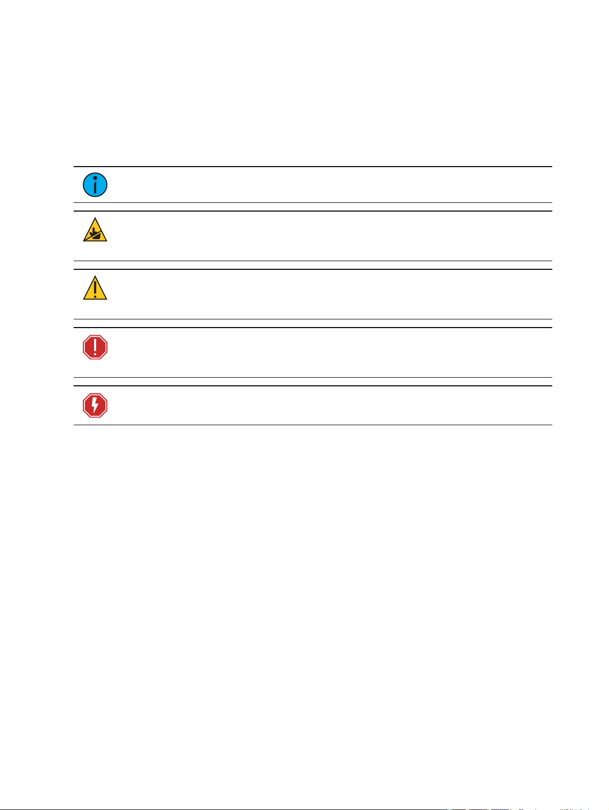
Note:
CAUTION:
surface s may reach very high tempe rature s. Allow the fi xture to cool before
handling or servicing.
CAUTION:
undefined or unwanted consequences of an action, potential for data loss or
an equipment problem.
Notes are helpful hints and information that is supplemental to the main text.
This sta tement indicates that while ope ra ting, equipment
A Caution statement indicates situations where there may be
WARNING: A Wa rning sta tement indicates situa tions where damage may
occur, pe ople may be harme d, or the re are serious or dangerous
consequence s of an acti on
WARNING: RISK OF ELECTRIC SHOCK! T his warning stateme nt indicate s
situa tions whe re there is a risk of electric shock .
Int roduct ion 3
Page 8
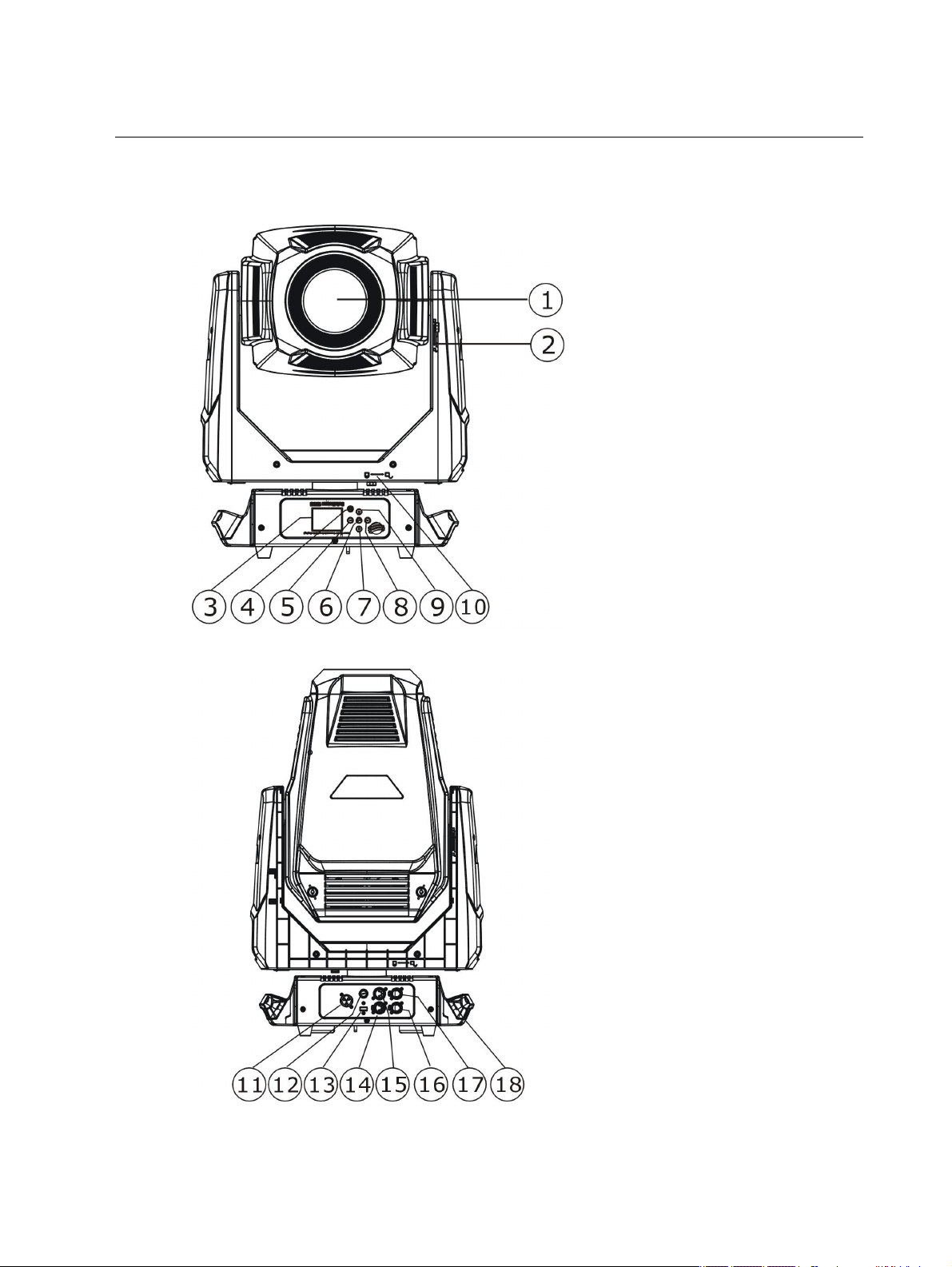
Fixture Overview
For technica l specifications of the SolaWash 1000 fixture, see the technical data sheet:
https://www.highend.com/documentation/SolaWash1000/Sola Wash1000-Datasheet.pdf
1: Lens
2: Tilt lock
3: Display
4: [MODE/ESC] button
5: Left button
6: [Enter] button
7: Down button
8: Right button
9: Up button
10: Pan lock
11: Power in
12: Fuse
13: USB
14: DMX In
15: DMXThru
16: Ethernet
17: Ethernet
18: Handle
4 SolaWash 1000 User Manual
Page 9
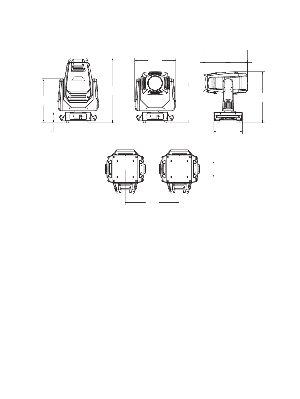
Dimensions
19.7in
[500mm]
12.7in
[324mm]
22.6in
[574mm]
11.1in
[282mm]
8.6in
[218mm]
17.5in
[444mm]
18.1in
[460mm]
28.6in
[726mm]
19.5in
[495mm]
4.7in
[118mm]
7.1in
[180mm]
23.8in
[605mm]
Dimensions shown are listed as inches [millimeters].
Fix ture Over view 5
Page 10
Safety Considerations
•
•
•
•
•
•
•
•
•
•
•
•
•
•
•
In order to ensure safe operation, follow the safety instructions and warning notes in this user
manual and any instructions from the manufa cturer re presentative.
The SolaWash 1000 fixture is inte nded for professional use only. Not for residential use.
Read the entire manual before using this equipment.
Conta ct your High End Systems dealer or High End Systems technical support before
performing any service in order to maintain warranty coverage .
WARNING: For your safe ty, read the following warnings and notice s
before use:
This equipment is designed for operation by qualified pe rsonnel only .
Di sconnect the unit from power and DMX a nd data before servicing.
Replace fuses with the specified type and rating only.
Mak e sure that the a vaila ble voltage is within the stated range.
NE M A Type 1 enclosure , indoor use , dry locations only. Do not use
outdoors. This fixture is intended for use where humidity does not
exceed 90% (non- condensing) .
Do not use this fixture with a da maged power lead (cord set) . If the
le a d is damaged, it must be replaced by a qua lified technician with an
equival ent type before use. Conta ct your local authorized dealer for
spa re power leads.
Do not use this fixture if the lens, protection scre e n, or ultraviolet
screen is damage d. Dama ge d lenses must be replaced before use.
Contact y our loca l authorize d deal er for a replacement.
When the fix ture has be en store d or tra nsported in cold tempe rature s,
allow it to warm to room te mpera ture for a minimum of one hour
before applying powe r. Applying power to a cold fixture may cause
dama ge to the fixture a nd void the ma nufacturer warranty .
This is a Cla ss 1 device and must be grounded. Follow national and
local codes.
Do not project the beam onto combustible substa nces.
Ke ep fixture head at le a st 0.1 m ( 0 .33 ft) away from any fl ammable
ma te ria ls.
Minimum distance to lighted obje cts:2 m (6 .56 ft).
When you powe r on the fixture, you may notice smoke or odor. This is
normal and should decrease gradually. If smoke or odor persists,
disconne ct the fixture from powe r a nd contact your High End Syste ms
dealer or High End Systems technical support.
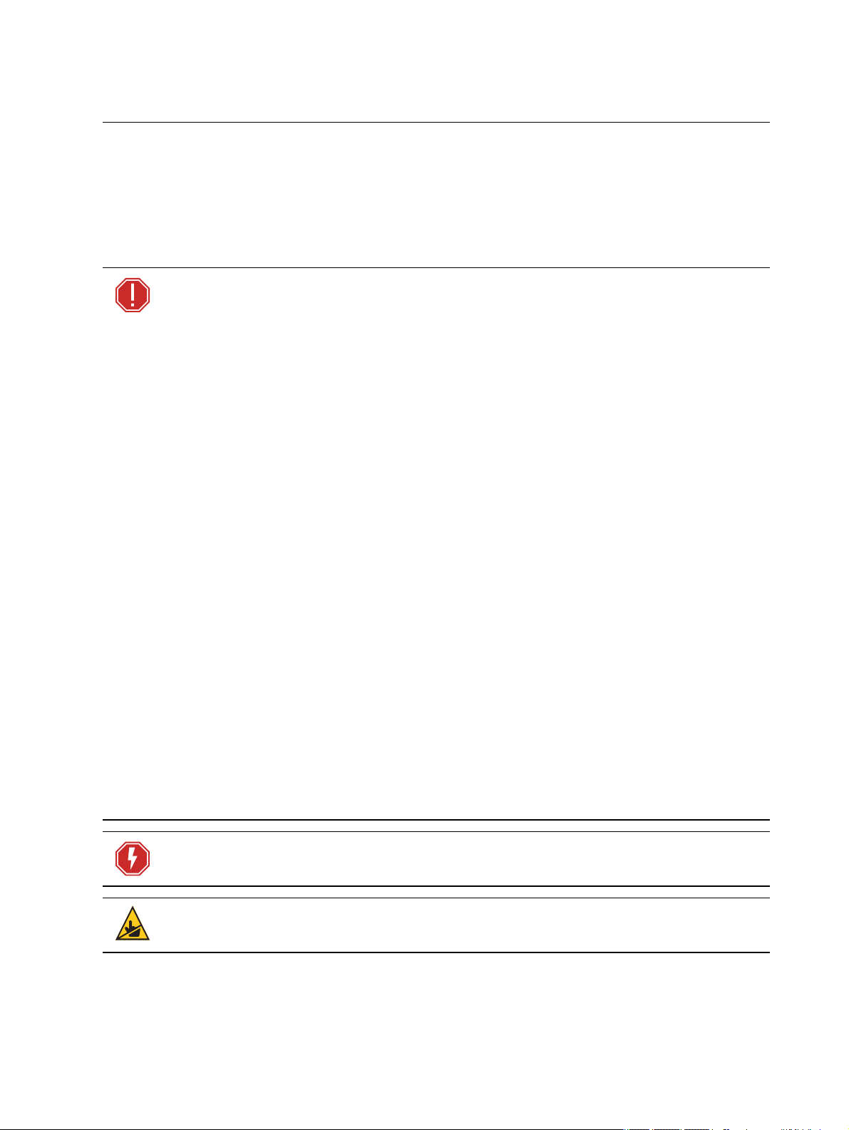
WARNING: RISK OF ELECTRIC SHOCK! D o not operate this de vice with the
cover open.
CAUTION:
handling and servicing.
6 SolaWash 1000 User Manual
Hot Surfaces. Allow the fixture to cool completely before
Page 11

CAUTION:
•
•
•
•
•
•
•
•
•
•
•
•
Damages caused by the disregard of this user manual are not
subject to warranty. The authorized dealer will not accept liability for any
resulting defects or problems.
General Operation and Use Guidelines
This fixture is only allowed to be operated with the maximum alternating current that is
stated in the te chnical specifications labe l provided on the fixture.
Lighting effects are not designed for permanent operation. Consistent operation breaks
may ensure that the fixture will serve you for a long time without defects.
Do not shake the fixture. Avoid brute force when installing or operating the fixture.
When choosing the installation location, make sure that the fixture is not exposed to
extreme heat, moisture or dust.
If using the supplied Ome ga brackets with quick-locking thumb scre ws for fixture hanging,
ensure that the thumb screws have engaged a comple te 90-degree positive latch.
Operate the fixture only after ha ving familia rized yourself with its functions. Do not permit
other persons who are not qualified and familiar with its functions to operate the fixture.
Please use the original packaging if the fixture is to be transported. ETC and High End
Systems, Inc. will not be responsible for the fixture if pack aging other than manufacturer
provided packa ging is used.
Do not modify the fixture. Any modifications will void the manufacturer warra nty.
This manual describes the proper installation and operation of this fixture. Using this
fixture in any way other than the intende d use may cause damage and may void the
factory warranty.
Misuse of this fixture or using it in a way different from the methods described in this
manual may lead to personal injury a nd/or equipment failure.
The light source of this fixture is not replaceable. When the light source re aches its end of
life, replace the fixture.
If you do not provide power to the fixture, the battery on the SolaWash 1000 may drain
fully after 7–10 days. After you provide power to the fixture, the ba ttery will recharge
within 3–4 hours.
Safety Considerations 7
Page 12

Install the Fixture
•
•
•
•
•
•
•
•
•
•
WARNING:
The installa tion location must support a minimum point load of 10
times the weight of the fixture.
The installa tion must always be secured with a seconda ry sa fety
attachme nt. A n a ppropriate safety cable is supplied.
Sa fety cable a ttachment must be rated by a safety factor of 10 .
Use of third party clamps are permi tted, but they should comply with
the loca l jurisdiction and be approved by the Authority Having
Jurisdiction.
A supportive a nd sta ble surface must be used when the fixture s are
placed on the feet.
The ope ra ting temperature ra nge for this fixture is - 1 0°C–45°C ( 14°F–
113°F) . Do not operate the fixture outside of this range .
Ne ver stand dire ctly be low the installe d fixture when mounting,
removing, or servicing the fixture.
Al l safety and te chnica l aspects of fixture installation must be
approve d by a qualified person be fore ope ra tion.
The installa tion must be regul arly inspected by a qualified person.
Overhead rigging must be performed by qualifi ed personnel.
CAUTION:
Follow all local codes and recommended practices by the
Authority Having Jurisdiction. The installation must only be carried out by
qualified personnel.
You can install the fixture in any of the orientations shown below.
8 SolaWash 1000 User Manual
Page 13

1
2
3 5
1. Assemble the clamp (provided by others) to the O me ga bracket and se cure toge ther using
appropriately sized hardware ( not provided).
2. Align the assembled Omega bracket and quick-lock fasteners into the respective holes on
the bottom of the fixture upper enclosure.
3. Tighten each of the quick-lock fasteners fully, turning clockwise. You will hear and feel a
click when the fastener is fully secured.
4. Repeat steps 1 through 3 for the second clamp and bracket.
5. Attach the provided safety cable through the attachment point on the bottom of the
fixture upper enclosure and secure to the trussing system or other safe installation point.
Follow local codes and recomme nded safety standards for securing the fixture to the
installation location.
6. Attach the fixture to the installation location using the installed clamps, using the clamp
manufacturer's instructions for a secure fit. When using the Omega clamp, close the
safety and fully tighten the clamp wing nut until secure.
7. Inspect the installation prior to lifting the fixture overhe ad.
Inst all the Fixture 9
Page 14

Power
Input and Power Factor
VAC Amps Hz Watts VA PF
100 9.7 50 967 973 0.99
120 7.8 60 930 937 0.99
200 4.6 50 896 921 0.97
208 4.5 60 898 922 0.97
220 4.2 50 930 920 0.96
240 3.8 60 867 900 0.96
CAUTION:
breaker to trip. Ensure that the circuit can handle the fixture's maximum
potential draw before you connect it.
Using this fixture below 100 V on a 15 A breaker may cause the
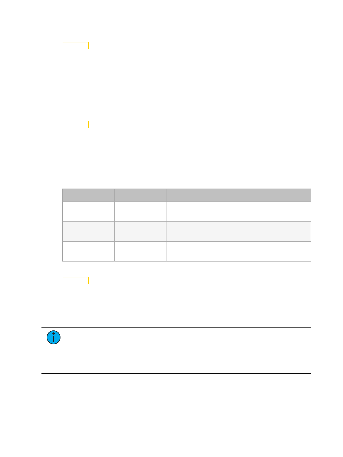
Connector Specification
A fixture power cord with powerCON TRUE1 input to bare end is provide d. Install a suitable
conne ctor to meet the installa tion requirements. See the following wire color code chart:
Wire Color Code (EU) Wire Color Code (US Standard) Connection type Terminal
Green/Yellow Green Ea rth/Ground
Blue White Neutral N
Brown Black Line (Live) L
WARNING: RISKOFE LECTRICSHOCK! The powe rCON T RUE 1 is a
connector sy stem consisting of the cable connector and the cha ssis
rece ptacle. A ca ble connector inserted the incorrect way could, in some
circumstances, lead to contact between live wires and the grounding contact
in the plug socket re sulting in equipment malfunction and/or personal
injury.
Che ck the condition of your powerCON TRUE1 connector syste m (cable
connector and cha ssis recepta cle ) for clear signs of wear and tear.
Refere nce the Neutrik Sa fety Notice powe rCON TRUE 1 for more safety
information.
10 SolaWash 1000 User Manual
Page 15

DMX Control
The SolaWash 1000 fixture ope rates on standard DMX512 control bus, controlled by a DMX
console. The fixture requires 37 cha nnels of DMX512 in standard mode.
Attach the fixture to the control bus using a two-core, shielde d cable with a 5-pin XLR connector
(Be lden 9729 is preferred).
Two XLR termination receptacles are available: one for connection of DMXInput, and one for
DMXThru (used when daisy-chaining to additional fixtures on the DMX control bus).
DMX Connector Pinout
For DMXInput, the DMX cable must have a ma le XLR conne ctor on one end of the cable. When
daisy-chaining DMX, the other end of the cable must have a female XLR connector. Terminate
the cable ends as indicated in the pinout image below.
DMX Cont rol 11
Page 16

Connect DMXCables to Fixture
DMX-512
(Belden 9729 or equivalent)
terminate DMX
with a 120 Ohm
resistor
DMX-512
control
source
The following instructions are guidelines for connecting DMX to your fixture. Your installation
may vary.
1. Conne ct the male XLR connector of a DMX data cable to the DMXThru connector on the
DMX control source.
2. Conne ct the female XLR connector of the DMX data cable to the DMX In connector of the
first fixture on the DMX control run.
3. Continue linking the remaining fixtures by connecting a cable from the DMXThru
conne ctor of a fixture to the DMXIn connector of the next fixture on the control run.
Note:
A maximum of 32 DMX devices may be connected in any one DMX data run
when installed in a daisy-chain fashion.
DMX Control and Ethernet Output
You can use DMX-512 control and Ethe rnet output. When a fixture is set up to receive DMX-512
control input, it conve rts the signal to ArtNet on IP10 and sends the signal to the Ethernet port,
continuing the ArtNet on IP10 signal to the next fixture in the control run.
Terminate DMX
For installations with a long DMX control run or an electrically noisy environment, we
recommend tha t you use a DMX terminator or install a resistor on the last fixture of the
DMXcontrol run to prevent corruption (data reflection) of the digital control signal by electrical
noise.
A DMXterminator is an XLR plug with a 120 Ω resistor connected between pins 2 and 3 that ca n
be installed into the DMX output receptacle of the last fixture in the DMX control run. This plug
is ava ilable and sold separately. Contact your loca l High End dealer for ordering information
(visit highend.com/about/contact-us to locate a High End dealer).
12 SolaWash 1000 User Manual
Page 17

Set the DMX Start Address
Give each fixture a unique DMX starting addre ss so that the correct fixture responds to the
control signals. This DMX start address is the channel numbe r from which the fixture sta rts to
“listen” to the digital control informa tion sent out from the control source.
Modify the fixture DMX start address on the user interface, located on the upper enclosure. See
DMX Address on page17
.
Example: The SolaWash 1000 has 37 channels. If you set the DMX starting address
of the first fixture to 1, you could set the second fixture to 38 (37+1), the third to 75
(38+37), and so on.
DMX Channels
The most current DMX Map data for the SolaWash 1000 can be found on the High End Systems,
Inc. website:
https://www.highend.com/documentation/SolaWash1000/Sola Wash1000-protocol.pdf
DMX Cont rol 13
Page 18

Ethernet Control
Cat5e or better
Ethernet
control
source
The SolaWash 1000 fixture includes two Ethernet ports that allow sending and receiving of
control signals using the Art-Ne t protocol or sACN.
Use a Cat5e (or better) cable and terminate to RJ45 connectors following the TIA/EIA 568B
wiring standard.
Connect EthernetCables to a Fixture
The following instructions are guidelines for connecting Ethernet to your fixture. Your
installation may vary.
1. Conne ct a cable from the E thernet control source to one of the Ethernet ports on the first
fixture in the E thernet control run.
2. Conne ct the first fixture to a second fixture by connecting a cable from the second
Ethernet port on the first fixture to one of the Ethernet ports on the second fixture.
3. Continue linking the remaining fixtures by connecting a cable from Ethernet port to
Ethernet port on the fixtures on the control run.
Note:
The Cat5e cable distance should not exceed 100 m, and you should not
conne ct more than 20 fixtures in one Ethernet control run when the fixtures are linked
together.
14 SolaWash 1000 User Manual
Page 19

Ethernet Control and DMX Thru
Ethernet
control
source
Universe 1 Universe 1 Universe 1
You can use Ethernet control a nd DMX Thru. When a fixture is set up to receive Ethernet control
input, it automatically distributes DMX via the DMX Thru port. The DMX-512 signal is sent as a
single universe that corresponds to the universe of the fixture that is rece iving Ethernet control.
Set the DMX Start Address
Give each fixture a unique DMX starting addre ss so that the correct fixture responds to the
control signals. This DMX start address is the channel numbe r from which the fixture sta rts to
“listen” to the digital control informa tion sent out from the control source.
Modify the fixture DMX start address on the user interface, located on the upper enclosure. See
DMX Address on page17
.
Example: The SolaWash 1000 has 37 channels. If you set the DMX starting address
of the first fixture to 1, you could set the second fixture to 38 (37+1), the third to 75
(38+37), and so on.
Set the Control Input and Universe
For Ethernet control, you must configure the control input (Art-Net on IP2, Art-Net on IP10, or
sACN) and set a universe (000-255) for each fixture. See
Universe for Art-Net on page20
for details.
Se lect Input on page20
and
Se t
Ethernet Cont rol 15
Page 20

Configure the Fixture
Mode
Esc.
Mode
Esc.
Mode
Esc.
You can configure SolaWash 1000 fixtures through the onboard user interface.
Navigate the User Interface
1.
Press the [MODE/ESC] button (
battery when the fixture has no power.)
2. Browse the menu by pre ssing the up, down, left, or right navigation buttons.
3.
Press the [Enter] button ( ) to se lect a me nu item.
4. Modify the selection by pressing the up, down, left, or right navigation buttons according
to the selection.
5.
Press the [Enter] button ( ) to confirm a modified selection.
6.
To exit the menu, press the [MODE/ESC] (
) to access the main me nu. (The display is powered by
)button.
Note:
If you press the [Enter] button to confirm a se lection and push no othe r buttons,
the user interface returns to the default display after 15 seconds.
16 SolaWash 1000 User Manual
Page 21

Set Fixture Parameters
•ON•
•ON•
This section provides instructions to configure and set up the Sola Wash 1000. Se e
User Interface on the previous page
Provide power to the fixture before configuring it. If you do not provide power, the fixture will
use battery power to power the user interface.
for information about the na vigation buttons.
Navigate the
DMX Address
Na vigate:Main Me nu → Address
Se t the DMX address for the fixture. The default value is 001.
Info Menu
Set the Time Information
Na vigate:Main Me nu → Info → Time Info
Pa rameter Value Description
Running time of the fixture from the last time that
Curre nt Time XXXX (Hours)
Ttl Life Hrs XXXX (Hours) Total running time of the device, shown in hours (h).
Last Run Hrs XXXX (Hours)
the fixture was powered on, shown in hours (h). The
counter resets after the fixture is turned off.
Running time of the fixture from the last time that
the run time value was reset, shown in hours ( h).
LEDHours XXXX(Hours)
Timer PIN Timer PIN XXX
Clr Last Run
LEDTime PIN
Clear LE D T ime
OFF
LED Time PIN
XXX
OFF
Total running time of the fixture LEDs, shown in
hours (h).
You must enter the Timer PIN in order to access the
Clr Last Run menu ite m. The default Timer PIN is
038.
This password-protected menu item resets the Last
Run Hrs value. You must enter the Timer PIN to
access this me nu item.
Se lect ON to clear the va lue for the Last Run Hrs
parameter for the fixture.
You must enter the LED Time PIN in order to access
the Clear LED Time menu item. The de fault LED
Time PIN is 038.
This password-protected menu item resets the LED
Hours value . You must enter the LE D Time PIN to
access this me nu item.
Se lect ONto clear the value for the LED Hours
parameter.
Configur e the Fixt ur e 17
Page 22

View Fixture Errors
Na vigate:Main Me nu → Info → Error Info
Displa ys any curre nt fixture errors. See
Error Codes on page25
for information about the errors.
View DMX Values for Channels
Na vigate:Main Me nu → Info → DMX Value
View the DMX value of each of the fixture's channels (parameters of the fixture). Scroll to the
parameter that you want to view (Pan, Tilt, etc. ) and vie w the va lue.
View Fixture Head Temperature
Na vigate:Main Me nu → Info → Head Temp
Displa ys the current fixture tempe rature as read from the fixture head (near the CMYfilter).
View Power Temperature
Na vigate:Main Me nu → Info → Power Temp
Displa ys the current temperature as read from the power supply in the fixture base, which can
help you to determine if the power supply is overheating.
View Fan Speeds
Na vigate:Main Me nu → Info → Fan Speed
Displa ys the speeds of the fixture's fans (in RPM).
View Sensor Status
Na vigate:Main Me nu → Info → LED Sensor
Displa ys the status of the se nsors, which can help you to determine whether the fixture is
recognizing the movement and position of the whe el. The display toggles be tween ON and OFF
as the magnet passe s the sensor.
View Ethernet IP Address
Na vigate:Main Me nu → Info → Ethe rnet IP
Displa ys the Ethernet IP address for the fixture. You can modify this value in the Set menu. See
Access Service Settings on page20
.
View Software Version
Na vigate:Main Me nu → Info → Software Ve r
Displa ys the software version for the fixture.
18 SolaWash 1000 User Manual
Page 23

Set Menu
•
•
•
•ON•
•ON•
•
•
•ON•
•
•
•
•
•
•
•
•
•
•
Set the Status Options
Na vigate:Main Me nu → Set → Status
Pa rameter Value Description
No DMX Mode
Pa n Reverse
Tilt Reve rse
Pa n Degree
Encoders
Pa n/Tilt Spd 1–4
Close Shutter
Hold
Auto Program
OFF
OFF
630
540
OFF
Control mode when DMXis absent. The de fault
value is Hold.
Reverse the pa n movement of the fixture. The
default value is OFF.
Reverse the tilt movement of the fixture. The default
value is OFF.
Change the pan rotation of the fixture from the
default setting of 540 degrees to 630 degrees.
Turn on or off the encode r feedback for pan and tilt
movement. You may want to turn off encoders when
working on a fixture so that you can move pan and
tilt without the fixture automatically moving back to
position.
Se t the speed (scan mode) of pan and tilt movement. The default value is 1. Use this parameter to
make fine adjustments to pan and tilt movement in
order to correct for mis-stepping when the fixture is
installed on its side (side-hung, or "Outrig").
Hibernation
Defogger
Dimming Mode
OFF
1–99 minute s
Defog OnOP
Defog OnPwr
Defog Off
Standard
Theatrical
Hibernation mode forces the LEDs and stepper
motors to power off when the fixture loses DMX control signal for a set period of time. The de fault time
setting is 15 minutes.
Se t when the Defogger (heater for the front lens)is
turned on:
Defog OnOP :Turn on Defogger when LEDs are
above 0% inte nsity
Defog OnPwr: Turn on Defogger when the fixture
is powered (default value)
Defog Off:Turn off Defogge r
Se t the dimming curve. The default value is Standard.
Configur e the Fixt ur e 19
Page 24

Select Input
•
•
•
•
•ON•
Na vigate:Main Me nu → Set → Select Input
Se lect the control input for the fixture:
DMX Only
Art-Net on IP2
Art-Net on IP10
sACN
Set Universe for Art-Net
Na vigate:Main Me nu → Set → Set Universe
When using Art-Net control input, se t the universe (000–255).
Access Service Settings
Na vigate:Main Me nu → Set → Service Setting
Pa rameter Value Description
You must enter the Service PIN in orde r to access
Se rvice PIN Se rvice PIN XXX
the other Service Se tting para me ters. The default
Se rvice PIN is 050.
This password-protected menu item lets you
modify the RDM UID. You must enter the Service
PIN to access this menu item.
Manufacturer ID
RDM UID
and fixture serial
number
Ethernet IP XXX.XXX.XXX. XXX
Ethernet
MaskIP
XXX.XXX.XXX.XXX
Note:Remote Device Management (RDM)
requires that all RDM devices have a unique
identifier (UID) that consists of the manufacturer
ID and serial number. Modifying this setting can
break the RDM capability of this fixture.
Duplicate RDM UIDs on the same DMX control run
will result in a data collision, causing a
communication failure. Ensure that all fixtures
have a unique RDM UID if RDM functionality is to
be used.
If DMX splitters are used and RDM control is to be
used, the se splitters must support RDM.
This password-protected menu item lets you
modify the IP address. You must enter the Service
PIN to access this menu item.
The default IP address is 002.142.058.034.
This password-protected menu item lets you
modify the IP subnet mask . You must enter the
Se rvice PIN to acce ss this me nu item.
The default IP subnet mask is 255.000.000.000.
Clr Err Info
20 SolaWash 1000 User Manual
OFF
This password-protected menu item lets you clear
Page 25

Pa rameter Value Description
•
•
•
•
•ON•
•ON•
•
•
error messages after you have fixed the errors.
You must enter the Service PIN to access this
menu item.
Se t this para meter to ON in order to clear the error
messages. T he default setting is OFF.
Set the Fans Mode
Na vigate:Main Me nu → Set → Fans Mode Setting
Se lect the fan mode for the fixture:
Standard
Studio (reduces fan noise, but decrea ses fixture output by ~20%)
Continuous
Studio Continuous (fa n runs continuously at a reduce d rate, but fixture output decreases
by ~20%)
Set Display Settings
Na vigate:Main Me nu → Set → Disp. Setting
Pa rameter Value Description
Enter the amount of time the fixture waits after the
Shutoff Time 02–60 minutes
last user interface button press until the display goes
to sle ep. The default value is 5 minutes.
Flip Display
OFF
Flip the display 180° when the fixture is mounted ve rtically. The default value is OFF.
Lock the user interfa ce. The default value is OFF.
Key Lock
OFF
To unlock the user interface buttons when locked,
press and hold the [MODE/ESC] button for thre e
seconds.
Set the Temperature Scale
Na vigate:Main Me nu → Set → Temp. C/ F
Se lect the temperature scale for the fixture:
Celsius (default value)
Fahrenheit
Update Fixture Firmware Using the USB Port
Na vigate:Main Me nu → Set → USB Update
Fixture firmware updates are available on the High End Systems, Inc. website at highend.com.
1. Sa ve the firmware upda te file to a US B drive.
2. Insert the USBdrive in the fixture base (see
location).
3. On the Main Menu, select Set → USB Update. The fixture reads the USBdrive and
displays a list of any firmware update files on the USB drive.
Fixture Ove rview on page4
for the USB port
Configur e the Fixt ur e 21
Page 26

4. Se lect the appropriate file and then press the [Enter] button.
•
•
•
5. The software prompts you to confirm the update with the message "Update fixture?" Use
the na vigation buttons to select "Yes," and then press the [Enter] button.
The firmware upda te begins. A progress monitor shows you the progress of the
update.
The fixture restarts when the update is complete, and the fixture performs a data
check to verify the update.
The firmware upda te is complete when the display re turns to its default state.
6. Remove the USBdrive from the fixture.
Reset Fixture to Factory Default Settings
Na vigate:Main Me nu → Set → Rese t Default
Se lect ON to reset the fixture to the factory default settings.
Test Menu
Reset (Home) the Mechanical Positions on the Fixture
Na vigate:Main Me nu → Test → Home
Reset ("home") all features on the fixture, including, pan, tilt, colors, gobos, etc.
Test the Fixture
Na vigate:Main Me nu → Test → Self Test
Run a self-test program on the fixture. When you run the test, the display indicates "Running"
and the fixture automatically runs a self-test procedure, testing each of the functions. Press
[MODE/ESC] button to end the self-test and return the display to the previous menu.
Test an Individual Channel
Na vigate:Main Me nu → Test → Test Channel
Run a self-test program on individual cha nnels. The default value is Control. Select a different
channel to run a self-test on that cha nnel.
Manually Set an Individual Channel
Na vigate:Main Me nu → Test → Manual Ctrl.
Se lect an individual channel on the fixture a nd ma nually set the cha nnel value. While in Manual
Control mode, all effects are cance led, the shutter opens, and the dimme r intensity is set to
100%.
Re-Calibrate an Individual Feature
Na vigate:Main Me nu → Test → Calibration
Please contact technical support at High End Systems, Inc. before using this parameter. Se e
Conta cting High End Systems on pa ge1
You must enter the Calibration PIN in orde r to access the Calibration menu items. The default
Calibration PIN is 050.
.
Once you have accessed the Calibration menu, select an individual feature on the fixture and
manually calibrate it to a new "home" setting.
22 SolaWash 1000 User Manual
Page 27

Preset Menu
•
•
•
Set the Playback Settings
Na vigate:Main Me nu → Preset → Play Back
Playback settings allow you to run an Auto Program as a Master fixture or in stand-alone mode,
or to receive playback information from a different Master fixture.
Prese t programming require s one fixture to act as the Master. All other SolaWash 1000 fixtures
that are connected to the designated Master fixture can then receive Auto Programs from the
Master fixture.
Example: You edit groups of scenes into Programs 1–10 on the Ma ste r fixture.
- Program 2 is assigned to Part 1
- Program 4 is assigned to Part 2
- Program 6 is assigned to Part 3
* Fixtures assigned as Slave 1 will play back Part 1
* Fixtures assigned as Slave 2 will play back Part 2
* Fixtures assigned as Slave 3 will play back Part 3
Se lect the appropriate playback setting:
DMX Control: Return the fixture to DMXcontrol from another playback mode.
Se t To Slave:Fixture will play back the Auto Program that is de fined on the Master fixture .
Auto Program:Fixture runs an Auto Program either in stand-alone mode or as a Ma ste r
fixture. Use the Select Prog parameter to select the program (see
below
).
Se lect an Auto Program
Select an Auto Program
Na vigate:Main Me nu → Preset → Select Prog.
Se lect the Auto Program that the fixture will run either in stand-alone mode or as a Master
fixture.
Program Range Default Value
Prog. Part 1 Program 1–Progra m 10 Program 1
Prog. Part 2 Program 1–Progra m 10 Program 2
Prog. Part 3 Program 1–Progra m 10 Program 3
Configur e the Fixt ur e 23
Page 28
Edit an AutoProgram
Na vigate:Main Me nu → Preset → Edit Progra m
Create the Auto Program that the fixture will run either in stand-alone mode or as a Ma ste r
fixture (see
Navigate to the Auto Program tha t you want to edit (Program 1, Program 2, etc.), and then set
the Scene (SC001, SC002, etc.)for each ste p (Ste p 01, Step 02, etc.) in the Auto Progra m. You
can set a maximum of 64 steps. T he SolaWash 1000 fixture provide s 250 pre-progra mmed
Scenes, or you can customize scenes using the Edit Sce nes parameter (see
Capture (Record) a Scene be low
Se lect an Auto Program on the previous page
).
).
Edit a Scene or
Edit a Scene or Capture (Record) a Scene
Na vigate:Main Me nu → Preset → Edit Scene s
The SolaWash 1000 fixture provides 250 pre -programmed Scenes that you can use or edit to
build an Auto Program. Each Scene is a snapshot of a set of fixture parameters (for example,
color, be am quality and pattern, intensity, focus, etc.) that you can assign to a step in an Auto
Program. Select the Scene (Scene 001, S cene 002, etc.) that you want to edit, and then set the
parameters for the Scene or capture the parameters for the Scene from the current DMX input.
In addition to standard SolaW ash 1000 features (pan, tilt, etc.), Sce ne parameters include the
following options.
Pa rameter Value Description
Fade Time 0–255 seconds
Scene Time
Input By Out
0.2–99.9
seconds
Enter the crossfade time applied to pa rameters when
the Scene plays.
Enter how long the Scene will play before the next
Scene plays. The default value is 0.3 seconds.
Capture the paramete r va lues for the Scene from the
current DMX input.
Capture (Record) Multiple Scenes
Na vigate:Main Me nu → Preset → Scenes Input
You can capture DMXdata and record those paramete rs as a series of Scenes. Select the sta rt
and end Scene numbers for the range of Scenes that you want to record. The fixture records the
incoming DMXdata into the se lected Scenes, with each change in DMX data triggering the next
Scene in the range. When all Scenes in the range have been recorded, the display re turns to the
main me nu.
Note:
the DMX input; it only captures the data. You must edit or play back the Scene after
recording is complete to verify the results. We suggest that you prepare the Scenes on a
DMX controller with a zero crossfade for all parameters betwee n steps. Remembe r that
any change of a DMXvalue will automatically advance to the next Scene during
capture.
While capturing the DMX data, the SolaWash 1000 fixture does not play back
24 SolaWash 1000 User Manual
Page 29

Error Codes
•
•
•
•
•
•
•
•
•
•
•
•
•
•
•
When you apply powe r to the fixture, it runs a calibration (homing) sequence and displays a ny
errors that it detects.
Example: For example, when the display shows “Err Info: Pa n Movement”, it means
there is an error in channel 1. When multiple errors are present they will cycle on the
display twice, and then the fixture will reset (restart). Any errors that remain after two
reset cycles are not correctable by reset alone and will require se rvice. Please contact
support if detailed assistance is needed.
Blade Rot Wheel
This message displays afte r the reset of the fixture if any of the following conditions exist:
the magnetic-indexing circuit malfunctions (optical or magnetic sensor failure)
the stepper motor is defective or the re lated IC driver on the ma in PCB has failed
the Blade Rotation move me nt is not located in the default position after the rese t
Color Wheel
This message displays afte r the reset of the fixture if any of the following conditions exist:
the fixture head's magne tic-indexing circuit malfunctions (optical or magnetic sensor
failure)
the stepper motor is defective or the re lated IC driver on the ma in PCB has failed
the Color wheel movement is not located in the default position after the reset
CMY Wheel
This message displays afte r the reset of the fixture if any of the following conditions exist:
the fixture head's magne tic-indexing circuit malfunctions (optical or magnetic sensor
failure)
the stepper motor is defective or the re lated IC driver on the ma in PCB has failed
the CMY movement is not located in the default position after the rese t
CTO Wheel
This message displays afte r the reset of the fixture if any of the following conditions exist:
the fixture head's magne tic-indexing circuit malfunctions (optical or magnetic sensor
failure)
the stepper motor is defective or the re lated IC driver on the ma in PCB has failed
the CTO movement is not located in the default position after the reset
Focus Wheel
This message displays afte r the reset of the fixture if any of the following conditions exist:
the magnetic-indexing circuit malfunctions (optical or magnetic sensor failure)
the stepper motor is defective or the re lated IC driver on the ma in PCB has failed
the Focus move me nt is not locate d in the default position after the rese t
Error Codes 25
Page 30

Frost 1 Wheel
•
•
•
•
•
•
•
•
•
•
•
•
•
•
•
This message displays afte r the reset of the fixture if any of the following conditions exist:
the magnetic-indexing circuit malfunctions (optical or magnetic sensor failure)
the stepper motor is defective or the re lated IC driver on the ma in PCB has failed
the Frost 1 movement is not located in the default position afte r the reset
Frost 2 Wheel
This message displays afte r the reset of the fixture if any of the following conditions exist:
the magnetic-indexing circuit malfunctions (optical or magnetic sensor failure)
the stepper motor is defective or the re lated IC driver on the ma in PCB has failed
the Frost 2 movement is not located in the default position afte r the reset
Pan Coarse
This message displays afte r the reset of the fixture if any of the following conditions exist:
the yoke’s magnetic-indexing circuit malfunctions (optical or magnetic sensor failure )
the stepper motor is defective or the re lated IC driver on the ma in PCB has failed
the Pan movement is not located in the default position after the reset
Tilt Coarse
This message displays afte r the reset of the fixture if any of the following conditions exist:
the fixture head magnetic-indexing circuit malfunctions (optical or magnetic sensor
failure)
the stepper motor is defective or the re lated IC driver on the ma in PCB has failed
the Tilt movement is not located in the default position after the reset
Zoom Wheel
This message displays afte r the reset of the fixture if any of the following conditions exist:
the magnetic-indexing circuit malfunctions (optical or magnetic sensor failure)
the stepper motor is defective or the re lated IC driver on the ma in PCB has failed
the Zoom movement is not loca ted in the default position after the reset
26 SolaWash 1000 User Manual
Page 31

Cleaning and Maintenance
•
•
•
•
•
Keep the following in mind during regular service and inspection:
All screws for insta lling the device or parts of the device must be tightly connected and
must not be corroded.
There must not be any deformations to the housing, lenses, rigging, and installation points
(ceiling, suspe nsion, trussing).
Moving parts must not show any signs of wear and must move smoothly without issue.
The power supply cables must not show any damage, material fatigue, or sediment.
If spare parts are required, order only genuine parts from your local authorized dealer.
CAUTION:
Disconnect the fixture from mains power before starting any
maintenance procedures.
In order to ensure that the device remains in good working condition and does not fail
prematurely, regula r maintenance is recommended.
1. Clean the inside and outside lens re gularly using a moist, lint-free cloth to avoid loss of
output due to accumulation of dust/dirt on the lens. Never use alcohol or solvents.
2. Clean the fans regularly to ensure maximum airflow and efficie nt cooling. This will ensure
that the light source operates in the best possible condition.
Cleaning and Maintenance 27
Page 32

Headqu ar te rs n 2105 Gr acy Far ms L ane, Aus ti n, TX, 75758 U SA
Tel + 512 836 2242 n Fax +512 837 5290 n 24 H ou r U rg ent Support : + 512 836 2242
Web : h ighend .com n © 2019 El ect ro ni c Theatre Contr ol s, Inc.
Pro duct in formati on and speci ficati on s s ub ject t o ch ang e.
ETCi nt ends th is docu ment to be p ro vid ed i n i ts enti ret y.
So l aWas h 1000 Us er Man ual Rev A R el eased 2019-09
 Loading...