

Page 1

Eos Family
(Eos Ti, Eos, Gio, Gio @5, Ion Xe, Ion Xe 20, and Element 2)
Operations Manual
Version 2.7.0
Part Number: 4250M1210-2.7.0 Rev A
Released: 2018-05
Page 2

ETC®, Eos®, Eos Ti®, Gio®, Gio@ 5®, Ion Xe™, Ion®, Element 2™, Element™, ETCnomad®, and ETCnomad Puck®
are either registered trademarks or trademarks of in the United States and other countries.
All other trademarks, both marked and not marked, are the property of their respective owners.
ETC intends this document, whether printed or electronic, to be provided in its entirety.
Page 3

Table of Contents
Introduction 9
Using this Manual 10
Register Your Console 10
Online Eos Family User Forums 10
Helpfrom ETC TechnicalServices 11
Other Reference Materials 11
Important Concepts 12
Console Overview 19
Eos Ti Geography 20
Eos Geography 21
Gio Geography 23
Gio@5 Geography 24
Ion Xe Geography 25
Element 2 Geography 27
ConsoleComponents 28
Cleaning Your Console 34
ConsoleCapacities 34
System Basics 37
About System Basics 38
The Central Information Area(CIA) 38
Browser 41
Softkeys 44
Displays 44
Display Control andNavigation 48
Live and Blind Displays 56
Playback Status Display 68
Using Direct Selects 76
Encoders 82
Moving Light Controls 86
Fader Configuration 87
VirtualKeyboard 96
sACN Output Viewer 97
Managing Show Files 99
About ManagingShow Files 100
Create a New Show File 100
Open an Existing ShowFile 100
Merging Show Files 103
Printing aShow File 105
Saving the Current ShowFile 107
Importing ShowFiles 108
Exporting a Show File 110
Exporting Logs 111
Deleting aFile 111
FileManager 112
Patch 113
About Patch 114
Patch Main Displays 115
Patching ConventionalFixtures 116
Patching Moving Lights, LEDs, and Accessories 122
Patching MultiCellFixtures 124
Labeling 125
Using the Scroller/WheelPicker andEditor 125
Settings in Patch 132
1
Page 4

Using Device List 136
Clearing the Patch 142
Update Library 143
Fixture Editor 143
Setup 151
About Setup 152
System 152
User 159
Device 162
Basic Manual Control 169
About Basic ManualControl 170
Using Channel Faders On Element 2 170
Selecting Channels 170
Setting Intensity 174
Manual Control of Non-intensity Parameters (NPs) 175
Home 189
Multiple Intensity Channels 190
Multicell Fixtures 190
Lamp Controls 192
Using [+%] and[-%] 193
Remainder Dim 194
Highlight and Lowlight 196
Sneak 197
Select Keys 198
ChannelCheck 200
Address at Level 200
Address Check 201
Flash 201
Using Groups 203
About Groups 204
Recording Groups Live 204
Selecting Groups 208
Opening the Group List 208
Using Groups as a Channel Collector 209
Using Fan 211
About Fan 212
Fanning Parameter Data 212
Fan From the Command Line 212
Fanning References 213
Fanning Timing and Delays 213
Using Subgroups with Fan 213
Using Mark 215
About Mark 216
AutoMark 216
Referenced Marks 217
Storing and Using Palettes 223
About Palettes 224
Palette Types 224
Palette Options 225
Storing Palettes Live 225
2
Page 5

Recalling Palettes 228
Editing Palettes Live 230
Editing Palettes in Blind 230
Using By Type Palettes 234
Removing Channels from a Palette 235
Deleting Palettes 235
Storing and Using Presets 237
About Presets 238
Preset Options 238
Storing Presets Live 238
Recalling Presets 240
Effects In Presets 241
Editing Presets Live 241
Using the Preset List 242
Editing Presets in Blind 243
Using By Type Presets 244
Removing Channels From aPreset 245
Deleting Presets 246
Presets and Palettes Fader Properties 246
Working with a Single Cue List 251
About SingleCue List 252
Basic Cueing 252
Recording Cues in Live 252
Using [Cue Only / Track] 254
Selective Storing Cues in Live 255
Timing 256
Assigning Cue Attributes 259
Flags 265
Using ExternalLinks 267
Modifying Cues Live 268
[Update] 270
Recording and Editing Cues from Blind 274
Deleting Cues 277
Using The Cue List Index 278
Using Filters 287
About Filters 288
Record Filters 288
PartialFilters 288
Clearing Filters 289
Storing Data with Record Filters 289
Working with Multiple Cue Lists 291
About Working With MultipleCue Lists 292
Recording to a New Cue List 292
Using [Go To Cue] with MultipleCue Lists 295
Advanced Manual Control 297
About Advanced ManualControl 298
Using [Copy To] 298
Using [Recall From] 300
Using {MakeNull} 301
Using {MakeManual} 303
Using {MakeAbsolute} 303
3
Page 6

Using [Capture] 303
Using [Query] 304
Using [Undo] 306
Cue Playback 309
About CuePlayback 310
Playback Controls 311
Selected Cue 311
Out-of-SequenceCues 312
VirtualFaders 315
Assigning Faders 315
Displaying Fader Pages With Content 316
Changing Fader Pages 317
Playback Fader Controls 317
Multipart Cues 325
About Multipart Cues 326
Record aMultipart Cue in Live 326
Storing aMultipart Cue in Blind 328
Deleting aPart from aMultipart Cue 329
Creating and Using Effects 331
About Effects 332
The Effect List 332
Effects Editor 333
Effect Status Display 337
Effect ChannelDisplay 339
Step Effects 340
Absolute Effects 343
Effect Background ValueModification 346
Beats Per Minute 346
Multiple Intensity HTPEffects 347
Relative Effects 348
Preprogrammed Rainbow Effects 350
Apply an Existing Effect 350
Editing Effects Live 350
Stop an Effect 351
Query and Group Effect 351
Using Offset 352
Replace With 352
Deleting anEffect 352
Recording an Effect to a Preset 352
Recording an Effect in a Cue 352
Effects on Faders 352
Delaying Effects 355
Using Park 357
About Park 358
Park Display 358
ParkedValues in Live 358
ParkedAddresses in Live 359
Park Values from the Park Display 360
Storing and Using Submasters 363
About Submasters 364
Paging Submasters 364
4
Page 7

Recording aSubmaster 364
Submaster List 365
Submaster Properties 365
Submaster Information 371
Labeling aSubmaster 371
Loading Submasters 371
Using Bump Button Timing With Submasters 372
Execute List 372
Freeze and StopEffect on Submasters 373
Moving and Copying Submasters 373
ReleasingContent From a Submaster 374
Updating a Submaster 374
Deleting aSubmaster 374
Using About 377
About [About] 378
[About] 379
{What's New} 380
[About] System 380
[About] Channel 381
[About] Address 383
[About] Cuelist 386
[About] Cue 387
[About] Curves 387
[About] Effects 387
[About] Groups 388
[About] Submaster 388
[About] Macro 388
[About] IFCB Palettes 388
[About] Presets 389
[About] Color Path 389
Storing and Using Curves 391
About Curves 392
Creating a Curve 392
Editing Curves 393
Applying a Curve To ChannelsIn Patch 394
Curves Appliedto Cues 394
Applying a Curve To Scroller Fans 395
Delete a Curve 395
Storing and Using Snapshots 397
About Snapshots 398
Recording Snapshots 398
Recalling Snapshots 400
Editing Snapshots 401
Deleting Snapshots 401
Storing and Using Macros 403
About Macros 404
Store aMacro from Live 404
Using the [Learn] key 404
Macro Editor Display 405
Create a New Macro from the Display 407
Edit an Existing Macro 407
Play aMacro 408
5
Page 8

Stop aMacro 409
Delete a Macro 409
Using Magic Sheets 411
About Magic Sheets 412
Magic Sheet Browser 412
Navigating a Magic Sheet 415
Creating and Editing Magic Sheets 416
Examples of Magic Sheets 431
Virtual Media Server 435
About Virtual Media Server 436
Media Content 436
Exporting MediaContent 437
Patching the V irtual Media Server and Layers 438
Creating a Pixel Map 438
Working with the Virtual Media Server 441
Effect Layers 446
PixelMapping in aMulti-ConsoleSystem 448
Using Partitioned Control 451
About Partitioned Control 452
How to UsePartitions 452
Setting Up Partitioned Control 452
Partition List 452
Creating New Partitions 452
Deleting Partitions 453
Using Partitions 453
Partitions in Playback 453
Partitions on Cue Lists 454
Flexichannelin Partitioned Control 454
Multi-console and Synchronized Backup 455
Overview 456
Multi-console Setup 456
Synchronized Backup 460
Mirror Mode 463
Eos Configuration Utility 467
Overview 468
Eos Configuration Utility Reference 468
General Settings 469
Network Settings 475
Maintenance and Diagnostics 483
Buttons 488
Local I/O 488
RFR 490
Show Control 493
About EosFamily Show Control 494
Show Control Settings 495
Show Control Display 501
TimeCode 505
RealTimeClock (RTC) 510
Analog Inputs 512
sACN Input 516
6
Page 9

MIDI Show Control 518
String Interface 523
MIDI Raw 530
Open Sound Control (OSC) 539
Eos Family ShowControl Capabilities 560
Advanced OSC 562
Eos OSCKeys 579
Facepanel Shortcuts 609
Overview 609
Displays 609
Facepanel 610
Operations 610
Eos Family Hotkeys 612
7
Page 10

8
Page 11

Introduction
This chapter contains the followingtopics:
Using this Manual 10
Register Your Console 10
OnlineEos FamilyUser Forums 10
HelpfromETC TechnicalServices 11
Other ReferenceMaterials 11
Important Concepts 12
Introduction 9
Page 12
Using this Manual
This manual is for use with the Eos Titanium, Eos, Gio, Gio @ 5, Ion Xe, Ion Xe 20, Element 2, Eos
RPU, Ion Xe RPU, and ETCnomad Puck control systems. For topics that apply to all of the platforms,
Eos will be used. When a topic pertains to specific consoles, their names will be used.
In order to be specific about where features and commands are found, the following naming and
text conventions will be used:
Browser menus and commands are indicated in boldtext. For example: In the Filemenu, click
Open.
Alphanumeric keyboard buttons are indicated in all CAPS. For example, ALT or CTRL.
Facepanel buttons are indicated in bold [brackets]. For example, [LIVE] or [Enter]. Optional
keys are indicated in <anglebrackets>, for example, <Cue> or <Sub>.
Keys which are intended to be pressed or held simultaneously are indicated with the “and”
symbol. For example, [Load]& [TimingDisable].
Softkeys and direct selects are indicated in bold {braces}. A note about <More SK> (more
softkeys): this command is always indicated as optional, and is only indicated once in an
instruction regardless of how many pages of softkeys exist. This is because there is no way to
predict what softkey page you are on at any given time. Press MoreSoftkeys until you find the
required command.
References to other parts of the manual are indicated in underlined blue (for example, Intro-
duction (on theprevious page)). When viewing this manual electronically, click on the ref-
erence to jump to that section of the manual.
Note: Notes are helpful hints and information that is supplemental to the main text.
CAUTION: A Caution statement indicates situations where there may be undefined or
unwanted consequences of an action, potential for data loss or an equipment problem.
WARNING: A Warning statement indicates situations where damage may occur, people
may be harmed, or there are serious or dangerous consequences of an action.
Please email comments about this manual to: TechComm@etcconnect.com
Register Your Console
Registering your console with ETC ensures that you will be notified of software and library updates,
as well as any product advisories.
To register your console, you will need to enroll in “My ETC,” a personalized ETC website that
provides a more direct path of communication between you and ETC.
Register now at http://www.etcconnect.com/product.registration.aspx.
Online Eos Family User Forums
You are encouraged to visit and participate in the ETC Eos Family User Forum, accessible from the
ETC web site (etcconnect.com). This gives you access to an online community of Eos Family users
where you can read about other users’ experiences, suggestions, and questions regarding the
product as well as submit your own.
10 Eos Family Operations Manual
Page 13

To registerfor theETC FamilyUser Forum:
1. Go to ETC’s community web site (community.etcconnect.com).
2. You may register for the forum by clicking the “join” link in the upper right corner of the
page.
3. Follow the registration instructions provided by the community page.
Help from ETC Technical Services
If you are having difficulties, your most convenient resources are the references given in this user
manual. To search more widely, try the ETC website at etcconnect.com. If none of these resources is
sufficient, contact ETC Technical Services directly at one of the offices identified below. Emergency
service is available from all ETC offices outside of normal business hours.
When calling for assistance, please have the following information handy:
Console model and serial number (located on back panel)
Dimmer manufacturer and installation type
Other components in your system (Paradigm®, other control devices, etc.)
Americas UnitedKingdom
Electronic Theatre Controls Inc. Electronic Theatre Controls Ltd.
Technical Services Department Technical Services Department
3031 Pleasant View Road 26-28 Victoria Industrial Estate
Middleton, WI 53562 Victoria Road,
800-775-4382 (USA, toll-free) London W3 6UU England
+1-608 831-4116 +44 (0)20 8896 1000
service@etcconnect.com service@etceurope.com
Asia Germany
Electronic Theatre Controls Asia, Ltd. Electronic Theatre Controls GmbH
Technical Services Department Technical Services Department
Room 1801, 18/F Ohmstrasse 3
Tower 1, Phase 1 Enterprise Square 83607 Holzkirchen, Germany
9 Sheung Yuet Road +49 (80 24) 47 00-0
Kowloon Bay, Kowloon, Hong Kong techserv-hoki@etcconnect.com
+852 2799 1220
service@etcasia.com
Other Reference Materials
Help System
A key help system is contained within your system. To access help, press and hold [Help] and press
any key to see:
the name of the key
a description of what the key enables you to do
Introduction 11
Page 14
syntax examples for using the key (if applicable)
links to topics in the manual
Note: Key help is included on most tangible action buttons on your Eos console. This
includes most softkeys and touchbuttons as well as the traditional keys on the keypad.
Note: As with hard keys, the “press and hold [Help]” action can be used with softkeys and
touchbuttons as well.
Show Control Resources
The chapter on show control in this manual is intended to provide basic information specific to the
Eos Family show control system. You may want to explore additional resources to learn more about
show control.
The following resources are recommended:
John Huntington, Show Networks and Control Systems, (Brooklyn, NY:Zircon Designs Press,
2012)
The ETC Support Articles: http://www.etcconnect.com/Support/
Important Concepts
Before using your console, you should read and familiarize yourself with the concepts defined
below. These concepts are important for understanding both howEos functions as well as how you,
as a programmer, will interact with your system to produce a successful show.
Channel
Address
RecordTargets
Cues
Cue List Ownership
SyntaxStructure
Parameters and Parameter Categories
Trackingvs. CueOnly
MoveInstruction
ManualData
MoveFade
Block vs. Assert
Live and Blind
HTP vs. LTP
Channel
A channel is a single numerical name that is used by Eos to control a dimmer, a group of dimmers, a
dimmer and a device, or a complete moving light fixture.
12 Eos Family Operations Manual
Page 15
Channel = Fixture
A fixture is defined as a group of related addresses that together control a device. An example of a
fixture would be an ETC Revolution. This moving light contains 31 parameters that together allow
you to perform various functions such as pan and tilt. Each of these attributes is addressed by a different output.
Eos treats fixtures and channels as one and the same. Unlike former ETC consoles where a fixture
occupied one channel for each parameter, Eos assigns each fixture a single channel number. Individual parameters are then associated with that channel as additional lines of channel information.
When you select a channel number, all of the controllable properties or parameters of that channel
are available through the keypad, level wheel, or the encoders.
Note: Multicell fixtures are handled differently. They are fixtures made up of multiplechan-
nels and addresses. See Patching MultiCell Fixtures (onpage124)and Multicell Fixtures (on
page190)for more information.
Address
Addresses are numerical identifiers set on the actual dimmers, moving light fixtures, or other devices
you want to control. To connect addresses to channels, you will need to use the Patch function of
Eos. For more information, About Patch (on page114).
Note: You can patch more than one address to a single channel, but you cannot patch mul-
tiple channels to a single address.
Syntax Structure
Most instructions can be entered into Eos through the command line. The command line expects
instructions to be entered in a specific structure, or syntax.
Generally speaking, the order of syntax can be described as:
What are you trying to affect? (Channel, group)
What do you want it to do? (Change intensity, focus, pan/tilt)
What value do you want? (Intensity at full, Iris at 50)
Naturally other commands will be used in the course of programming your show, but most other
functions are modifiers of these three basic steps: modifying the channel(s) you are working with,
determining what parameters of those channels you are impacting, and what value you want them
to assume. When working with RecordTargets(onthe next page), the syntax is similar.
Note: Not all actions must be entered from the command line, although many will result in
a command lineinstruction. Other actions bypass the command line entirely.
Enter
Since the command line can receive multiple edits and instructions at once, it is necessary to let Eos
know when you have completed your instruction in the command line. This is done with the [Enter]
Introduction 13
Page 16
key.
There are some commands which are self-terminating, and therefore do not require [Enter]to be
pressed. Some (but not all) of these commands are:
Out
+%
-%
Level
Actions from the direct selects
Parameters and Parameter Categories
Eos divides fixture parameters into four major parameter categories: Intensity, Focus, Color, and
Beam.
These are the parameters in each category:
Intensity- Intensity
Focus- Pan and Tilt
Color - All color parameters (such as color wheel, CMY, scrollers, and so on).
Beam- Any parameter not covered in the other categories.
Note: Throughout this manual, non-intensity parameters will be referred to as NPs.
Record Targets
A record target is any data location that you can store data using a [Record] command. Examples of
record targets are cues, palettes, and macros.
Cues
A cue is a record target comprised of channels with associated parameter data, discrete (channel/parameter level) timing, cue timing, and cue attributes (such as preheat, followor hang instructions).
Tracking vs. Cue Only
Eos is, by default, a tracking console. This means two things. First, tracking relates to how cue lists
are created. Once data is in a cue list, it will remain a part of that cue list, at its original setting, until a
new instruction is provided or until it is removed from the cue list using filters or null commands.
Secondly, tracking relates to how changes to cue data are handled. Unless otherwise instructed by a
Cue Only command, changes to aparameter in a cue will track forward through the cue list until a
move instruction (or block command) is encountered.
It is possible to change the default setting of Eos to “Cue Only” in About Setup(on page152). This
prevents changes from tracking forward into subsequent cues, unless overridden with a track
instruction. See Track (onpage160)for more information.
14 Eos Family Operations Manual
Page 17
Eos also has a [CueOnly/Track]button that allows you to record or update a cue as an exception to
the default setting. Therefore, if the console is set to Tracking, the button acts as Cue Only. If console is set to Cue Only, it behaves as a Track button.
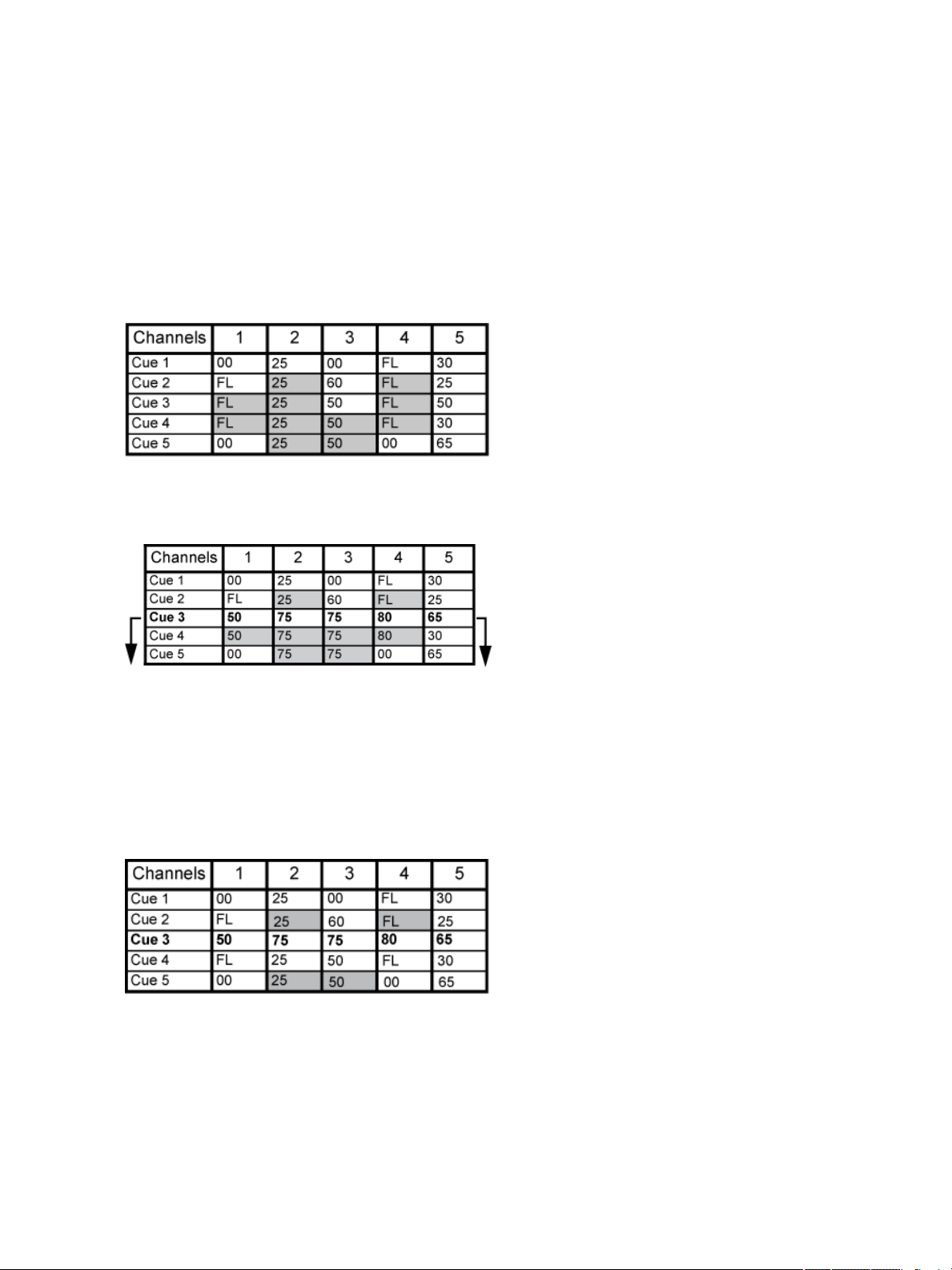
Tracking Mode
When you create a new cue, any unchanged channel parameter data from the previous cue is
tracked into the new specified cue. Any changes in this new cue will also track forward into subsequent cues until a move instruction or a block flag is encountered. In the example below, the gray
boxes indicate tracked values and the white boxes indicate move instructions.
When in tracking mode, edits made to an existing cue will track forward through the cue list until a
move instruction is encountered. Changes made to Cue 3 will affect the cue list as shown below in
bold.
Cue Only Mode
The [CueOnly/Track]key is an exception to this behavior. [CueOnly/Track] button combined with
[Record] or [Update] modifies standard tracking behavior. When you record a cue in the middle of
the cue list, using the [Q Only] button will prohibit new information from tracking into the sub-
sequent cue, and will protect the previously tracking levels by adding a move instruction into the
next cue for those levels. When you rerecord or update a cue, the modifications will not track forward. Using [Record] <Cue> [3][Q Only] [Enter] would affect the cue list as shown below.
Using Trace
{Trace} works just like Tracking mode, except it allows changes to be tracked backwards though the
cue list, until it sees a move instruction. In the example below, the channel levels have been adjusted
while cue 3 is live on stage. Using Trace will take those adjusted levels and update them into the cues
Introduction 15
Page 18
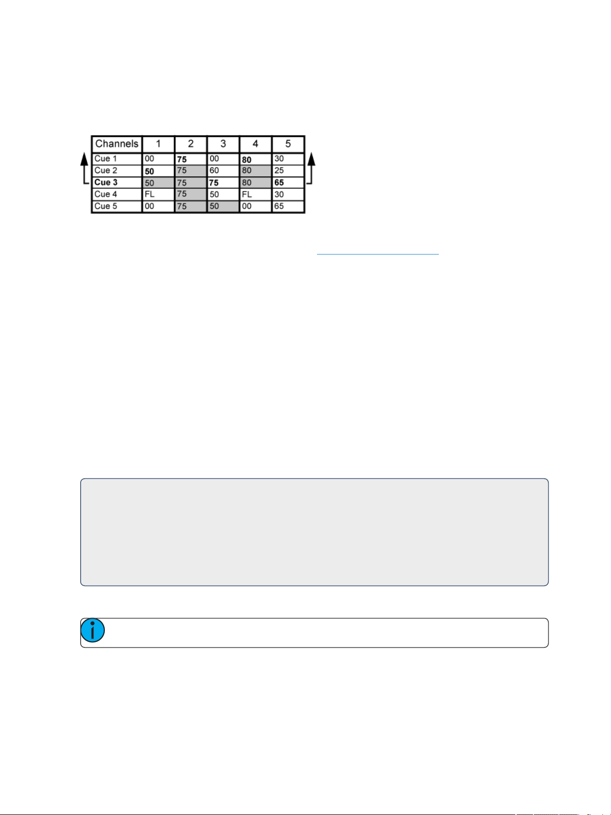
as follows: channel 1's new level is recorded into cue 2, channel 2's level is recorded into cue 1, and
channel 3's level is recorded into cue 3. This is because the move instruction for those channels are
contained in those cues. In the case of channels 1 and 2, their new level will track into cue 3.Using
[Record] <Cue> [3]{Trace} [Enter] would affect the cue list as shown below in bold.
To force that channel’s new value to go backward in the cue list, {Trace}{Trace} can be used.
For information on using [Update] and {Trace}, See UsingTrace (onpage273).
Move Instruction
A move instruction is any change to a parameter from its previous stored value. A change to a channel’s intensity is a move instruction. A change to a channel’s pan or tilt is a move instruction. A
change to a channel’s color mixing is a move instruction, and so on.
Manual Data
Manual data is any value set for achannel via the command line. Manual data will remain at its value
until a move instruction is provided for it.
Move Fade
Move Fade is a lighting control philosophy which determines how cues are played back. Eos adheres
to this philosophy.
In a Move Fade system, parameters do not change from their current setting until they are provided
a move instruction in a cue or are given a newinstruction manually.
For Example:
In cue 1, channel 1 has been given an intensity valueof 50%. This value does not change
until cue 20, where channel 1 is moved to 100%. Therefore, channel 1 has a tracked intensity value of 50% in cues 2-19. If the user applies amanual intensity value of 25% while sitting in cue 5 (for example), that channel will stay at 25% until Cue 20 is recalled - because
20 is the next cue in which channel 1 has a move instruction.
Cue List Ownership
Note: Multiple cue lists are not available on Element 2.
Eos is capable of running multiple cue lists. Cue list ownership is determined by the cue from which a
channel is currently receiving its value. In Live, a parameter is considered to be “owned” by a cue list
when it is receiving its current value from that cue list.
16 Eos Family Operations Manual
Page 19

When alternating between cue lists in sequential playback, an active cue list does not necessarily
own a channel unless that list has provided the last move instruction for that channel. For example,
assume a channel is owned by cue list 1 and is at a tracked value. If a cue from another cue list is
executed and provides a move instruction for the channel in the new cue, the channel is now owned
by the second cue list. It will not return to cue list 1 until that cue list provides a move instruction for
the channel.
Assert may be used to override this default behavior, allowing a cue list’s control over a channel to
resume, even when the channel’s data is tracked.
This rule is not followed when executing an out-of-sequence cue. An out-of-sequence cue is any cue
that is recalled via [Go ToCue], a Link instruction, or manually changing the pending cue. In general
applications, the entire contents of the cue (both moves and tracks) will be asserted on an out-ofsequence cue.
Block vs. Assert
In previous ETC consoles, placing a block instruction on a channel was a way to treat a tracked value
as a move instruction, both in editing and playback. In Eos, this behavior is now split up. Blocked
channel data is an editing convention only, and it prohibits tracked instructions from modifying the
associated data. Blocked data has no impact on playback; the channels will continue to play back as
though they were tracks. Assert is used to force playback of a tracked/ blocked value.
Assert is not available on Element 2.
Live and Blind
Live and Blind are methods to view and edit data in your show files. When you press the [Live]key,
the screen will show you the live display. When you press [Blind], you will see the blind display. In
either case, you may use the [Format]key to alter how the data is displayed (see Using[Format] (on
page56)).
When in Live, the data displayed represents the data being sent from the console at that moment. In
other words, the parameter data that is “live” on stage. When you edit data in live, those changes
will become active and visible on stage as soon as the command line is terminated, unless auto playback has been disabled in Setup. See Auto Playback (onpage160)for more information.
When in Blind, the data displayed represents data from the record target you choose to view (cues,
presets, palettes, and so on). When you edit data in Blind, changes will not automatically appear on
stage, since the data you are modifying is not live. This is true even if the record target you are modifying is active on stage. It is possible to play a cue in Live, then switch to Blind and edit that cue in
blind without affecting levels on stage. Edits in Blind do not require a [Record] command to be
stored. They are considered stored when the command line is terminated. Any display that is not the
Live display is considered Blind, and the Blind LED will be illuminated. For example, if you open patch,
the blue LED on [Blind] will be lit to show that you are in a Blind display.
HTP vs. LTP
HTP (Highest-Takes-Precedence) and LTP (Latest-Takes-Precedence) are terms used to define the output of achannel parameter that is receiving data from multiple sources. In HTP, the highest level of
all sources will be executed. In LTP, the most recent level received will be executed. Cue lists can operate as HTP or LTP for intensity parameters only. Non-intensity parameters (NPs) are always LTP.
Introduction 17
Page 20

Submasters can operate as HTP or LTP for intensity. The default is HTP. Eos’s default cue list setting
for intensity is LTP.
HTP
HTP is only applicable to the intensity of a channel. HTP channels will output the level that is the
highest of all inputs. HTP channels are also referred to as “pile-on”, because as control inputs are
added (for example - you may bring up cues and multiple submasters that all have the same channel
recorded at various levels), the system calculates which input has the highest level for that channel
and outputs that level for the channel. As control inputs are removed (you pull some of the submasters down to zero), the console will adjust the channel level, if required, to the highest remaining
level.
LTP
LTP is applicable to any parameter of any channel. LTP output is based on the most recent move
instruction issued to the channel parameter. Any new values sent to the channel will supersede any
previous values, regardless of the level supplied.
Eos determines the LTP value for a channel, which is overridden by any HTPinput values that are
higher than the LTP instruction. This is then finally modified by manual control.
18 Eos Family Operations Manual
Page 21

C h a p t e r 1
Console Overview
Inside this section you will find general descriptions of your console and various areas of theuser
interface.
This chapter contains the followingtopics:
Eos TiGeography 20
Eos Geography 21
GioGeography 23
Gio@5 Geography 24
Ion XeGeography 25
Element 2 Geography 27
Console Components 28
CleaningYour Console 34
Console Capacities 34
ConsoleOverview 19
Page 22
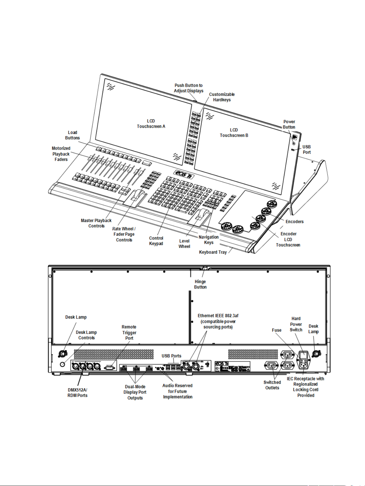
Eos Ti Geography
Below is a diagram of Eos Ti with references made to specific areas of use. The terms and names for
each area and interface are used throughout this manual.
20 Eos Family Operations Manual
Page 23
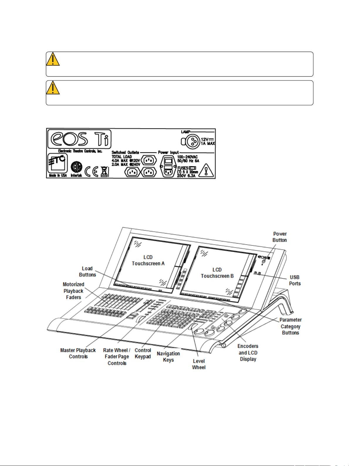
Eos Ti Fuse Replacement
CAUTION: For continued protection against risk of fire, replace only with same type and rat-
ing of fuse.
CAUTION: Pour ne pas compromettre la protection contre les risques d’incendie, remplacer
par un fusible de même type et de mêmes caractéristiques nominales.
Fuse replacement information and additional electrical ratings can be found on this label located on
Eos Ti’s rear panel.
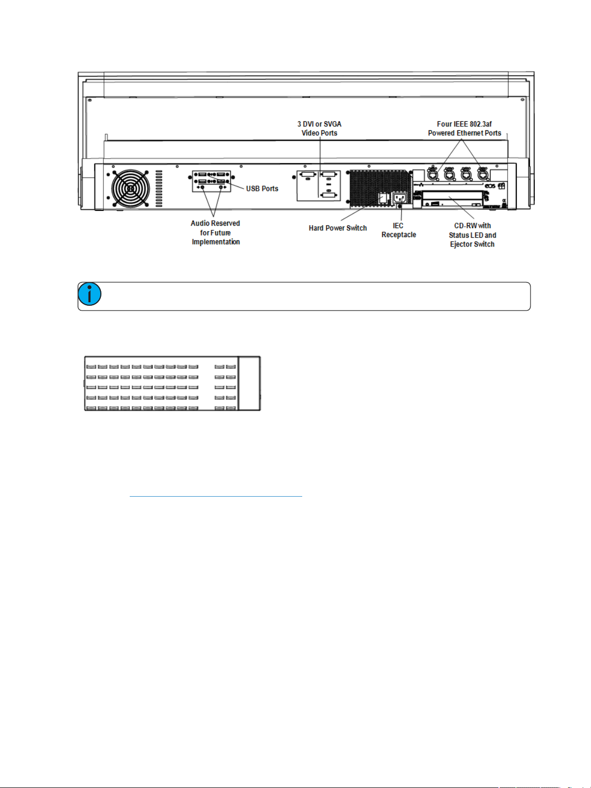
Eos Geography
Below is a diagram of Eos with references made to specific areas of use. The terms and names for
each area and interface are used throughout this manual.
ConsoleOverview 21
Page 24
Eos Button Modules
Note: Button modules are only for use with Eos consoles.
The Eos button modules provide the ability for multiple simultaneous button presses with tactile feedback. The displays and text above each button change to reflect the current mapping of the button.
Button modules are available in a 50 button array for use with the direct selects. Button modules
provide you with tactile feedback of each button press. The module is transparent allowing the text
and graphics from the LCD to repaint each button. Up to three button modules may be installed on
the console, two on LCD A and one on the top of LCD B, above the CIA.
LCD A (see Eos Geography (on theprevious page)) may be split into numerous sections using Eos
button modules and customized views. The top portion of LCD B is also user-configurable while the
bottom portion is reserved for the CIA.
Button modules are optional and therefore not required for operation.
Installing Button Modules
Should you desire to use the button modules over your direct selects, follow the instructions below
to install them.
It is recommended that you install the button modules with the console power off.
1. Place the left end of a button module in place over touchscreen area 1, 2, or 3. Align the
corner of the button module with the corner of the recessed touchscreen area.
2. Lay the right end of the button module in place and gently press until it is flush with the front
of the console. The direct selects will automatically appear once it is installed and the console
is powered up.
22 Eos Family Operations Manual
Page 25
3. To remove the module, slide the release latch (located to the right of the respective module)
upwards and pull the module out from right to left.
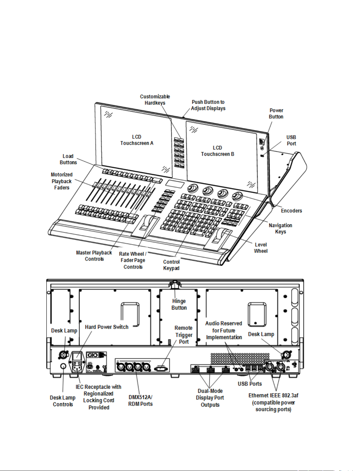
Gio Geography
Below is a diagram of Gio with references made to specific areas of use. The terms and names for
each area and interface are used throughout this manual.
ConsoleOverview 23
Page 26
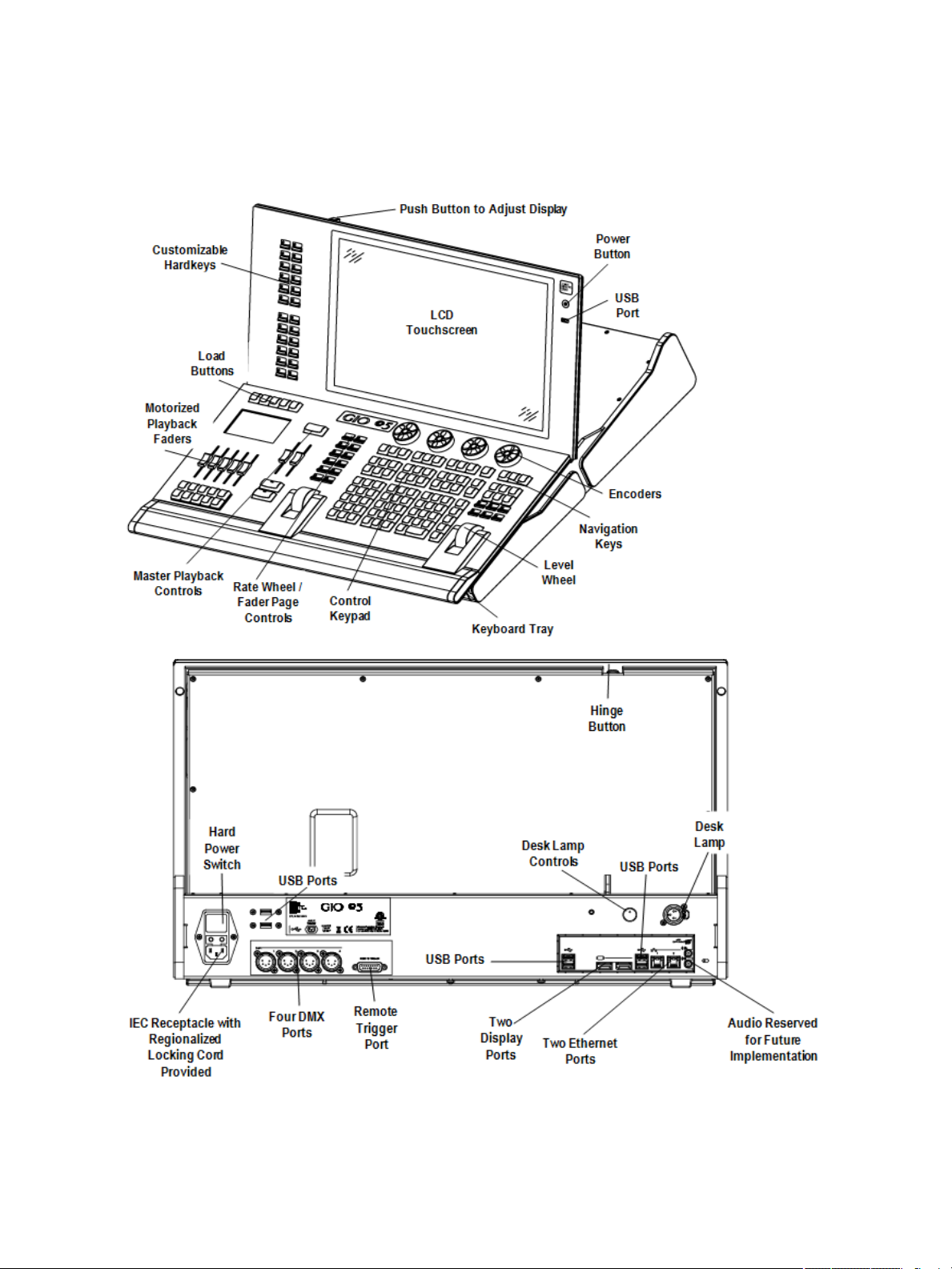
Gio@5 Geography
Below are diagrams of the Gio @ 5 console with references made to specific areas of use. The terms
and names for each area and interface are used throughout this document.
24 Eos Family Operations Manual
Page 27
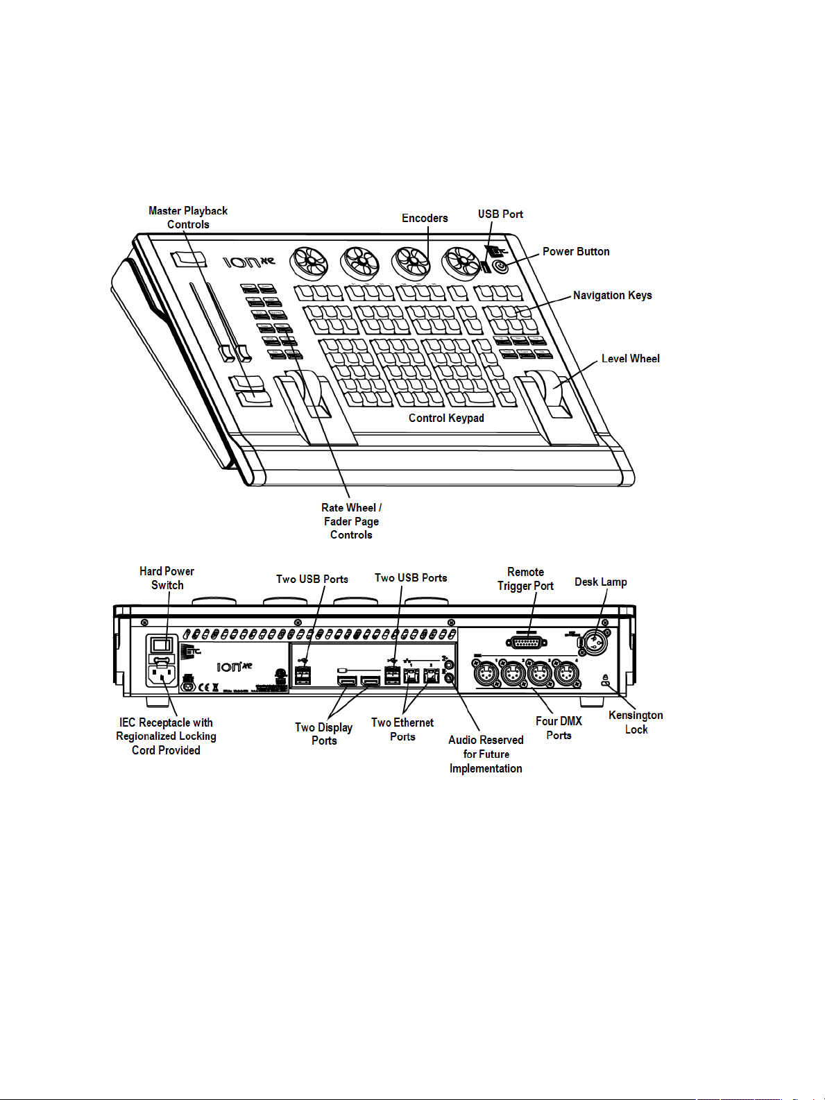
Ion Xe Geography
Below are diagrams of Ion Xe and Ion Xe 20 with references made to specific areas of use. The terms
and names for each area and interface are used throughout this manual.
Ion Xe
ConsoleOverview 25
Page 28
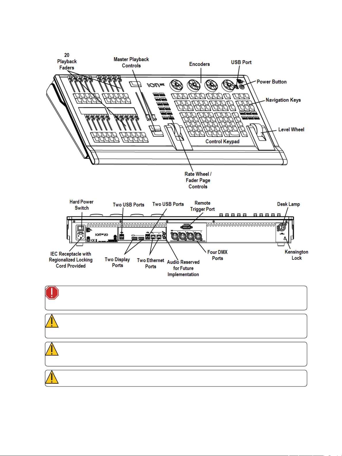
Ion Xe 20
WARNING: This device contains alithium battery. Battery may explode if mistreated. Do not
recharge, disassemble or dispose of in fire.
CAUTION: For continued protection against risk of fire, replace only with same type and rat-
ing of fuse.
CAUTION: Pour ne pas compromettre la protection contre les risques d’incendie, remplacer
par un fusible de même type et de mêmes caractéristiques nominales.
CAUTION: Power cord must be connected using an earth ground connection.
26 Eos Family Operations Manual
Page 29
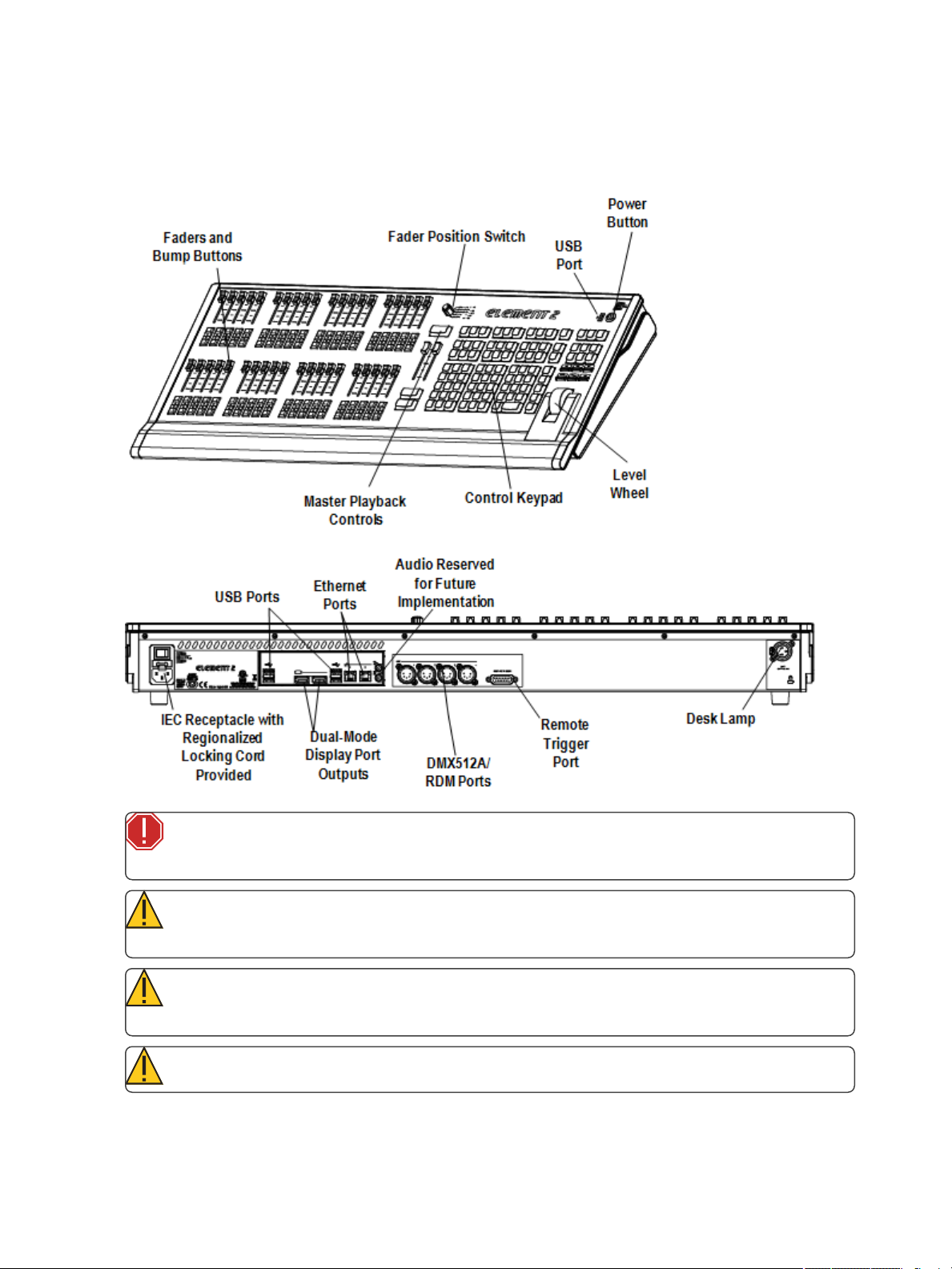
Element 2 Geography
Below is a diagram of Element 2 with references made to specific areas of use. The terms and names
for each area and interface are used throughout this manual.
WARNING: This device contains alithium battery. Battery may explode if mistreated. Do not
recharge, disassemble or dispose of in fire.
CAUTION: For continued protection against risk of fire, replace only with same type and rat-
ing of fuse.
CAUTION: Pour ne pas compromettre la protection contre les risques d’incendie, remplacer
par un fusible de même type et de mêmes caractéristiques nominales.
CAUTION: Power cord must be connected using an earth ground connection.
ConsoleOverview 27
Page 30
Console Components
This section discusses the various console components that were called out in the geography section.
Power Button
USB Ports
Touchscreens
ExternalMonitors
BacklitKeys
ControlKeypad
Navigation Keypad
Fader Control Buttons
Rateand FaderPage
Grandmaster and Blackout
LevelWheel
Master Playback Controls
Encoders
CustomizableHardkeys
Parameter andCategory Buttons
LoadButtons
Motorized Faders
EthernetPorts
Littlites®
Outputting DMX
Power Button
The power button on the front of the console is used to power up or power down. A separate hard
power switch, located on the rear panel, can be used to disconnect power from the console’s
internal components.
CAUTION: It is recommended that you safely power down the console through the soft-
ware, Displays>PowerOffDevice, before disconnecting power from the console.
WARNING: Before servicing your console, you must switch off the power on the rear panel
and disconnect the power cord completely.
USB Ports
One USB port is provided on the front of the console to connect any USB storage device. Additional
USB ports on the rear panel and in the keyboard tray of the console connect peripherals such as an
alphanumeric keyboard, pointing device, or touchscreen control for external monitors.
Eos has two USBports on the frong of the console, and additional ports on the rear panel.
28 Eos Family Operations Manual
Page 31

CAUTION: The USB ports cannot be used for charging devices such as cell phones.
Touchscreens
Eos Ti
Eos Ti is designed with three internal LCD touchscreen displays. LCD touchscreens A & B may be
used to display show data (with touchscreen interface), or they may be used as direct selects or a variety of other virtual controls and displays.
The touchscreen angle can be adjusted by pushing the button in the center top of the display and
moving the panel up or down.
Eos
Eos is designed with two internal 15” LCD touch screen displays. Each LCD may be used to display
show data (with touchscreen interface), or they may be used as direct selects, with or without the
button modules. A variety of other virtual controls and any display may be placed on the internal
touchscreens.
Gio
Gio is designed with two internal LCD touchscreen displays. Each LCD touchscreen may be used to
display show data (with touchscreen interface), or they may be used as direct selects or a variety of
other virtual controls and displays.
The touchscreen angle can be adjusted by pushing the button in the center top of the display and
moving the panel up or down.
Gio @ 5
Gio @ 5 is designed with an internal LCD touchscreen display.The LCD touchscreen may be used to
display show data (with touchscreen interface), or they may be used as direct selects or a variety of
other virtual controls.
The touchscreen angle can be adjusted by pushing the button in the left side top of the display and
moving the panel up or down.
Adjusting the LCD Brightness
The brightness level for the LCD touchscreens can be adjusted. This is done in Setup> DeskSettings>
BrightnessSettings> LCD.The range for the brightness level is 5-100%, with 100% being the
default setting. See Brightness Settings (on page167) for more information.
You can control the brightness by using a Live Master. See LiveMaster (onpage167) for more
information.
External Monitors
Eos, Eos Ti, and Gio support up to three external monitors. Eos supports DVI or SVGA. EosTi andGio
support Windows 7 compatible display port monitors.
ConsoleOverview 29
Page 32

Gio @ 5, Ion Xe, and Element 2 support up to two external Windows 7 compatible display port monitors.
Note: While it is possible to assign a resolution lower than the minimum (1280x1024), it is
recommended to be at 1280x1024 or higher.
For monitor configuration, please see Monitor Arrangement (onpage473).
Backlit Keys
Note: Backlit keys are not available on Eos and Element 2.
Backlit keys are provided on the facepanel. The brightness level for those keys can be adjusted in
Setup> Desk Settings> Brightness Settings> Backlight. See Brightness Settings (on page167).
You can control the brightness by using a Live Master. See LiveMaster (onpage167).
When your console has been idle for 10 minutes, thebacklit keys will fade their intensity down by
10%. Any key press on either the facepanel keypad, an external keyboard, move of the mouse, or
touch of a touchscreen will return the keys to their set intensity level.
Control Keypad
The control keypad area is divided into several sections including record targets, numeric keypad
with modifiers, display, softkeys, navigation, and special function controls.
Display and navigation keys are used for quick access to common displays, format, paging, and navigation within displays.
Navigation Keypad
Used for quick access to the Live and Blind displays, tab selection, location, paging and navigation
within displays.
Fader Control Buttons
Fader control buttons are provided for easy local control of fader behavior. Control buttons include:
[ManualOverride], [Spread], [Release], [Off], [Assert], [Go toCue0], [Stop Effect], [Freeze], [Filter],
and [TimingDisable]. Individual faders are provided with immediate controls including: Go, Stop and
Back (for playbacks), bump and assert/ group control (when submasters), or blackout and blackout
enable when configured as grandmasters.
On Element 2, the {Fader Control}softkey is used to access the fader control softkeys. Control
softkeys include: {ManualOverride}, {Rate}, {Release}, {Off}, {Assert}, {Go to C ue0}, {Stop Effect},
{Freeze}, {Filter}, and {TimingDisable}.
See Playback Fader Controls (onpage317)for more information.
Rate and Fader Page
[Rate] and [Fader Page]buttons are provided for use with the faders. [Rate] is used for rate control of
a fader. See UsingRate Override(on page320)for more information. [Fader Page]is used to access
additional pages of faders. See ChangingFader Pages (onpage317)for more information.
30 Eos Family Operations Manual
Page 33

On Element 2, {Rate} is part of the {Fader Control}options. Press [Live] to see the {Fader Control}
softkey. To changethe fader page on Element 2, press {PageSubs}. See Paging Submasters (on
page364)for more information.
Grandmaster and Blackout
The grandmaster inhibits all live intensity values. If the grandmaster is set at 50%, all live intensities
will be at 50% of their actual values.
Blackout sets all lighting levels to zero.
If a grandmaster is set to a value other than 100%, a grandmaster button with the set value will be
shown at the top of each display. If blackout is currently on, a blackout button will be shown at the
top of the displays.
Clicking on either button will open a new display which will allow you to turn off blackout and set the
grandmaster to a different level.
Level Wheel
Adjusts intensity for selected channels. It also provides scrolling and zoom functions in various
modes. SeeLevelWheel (on page175)for more information.
Master Playback Controls
The master playback fader pair is located to the left of the control keypad. The master is a split crossfader pair. The two buttons beneath the master fader pair are [Go]and [Stop/Back]. The[Load]but-
ton is located directly above the fader pair and is used to load a specified cue onto the master playback.
Encoders
Note: On Element 2, you can access encoder control by using the MLcontrols display. See
MovingLight Controls (on page86) for more information.
Eos and Eos Ti Encoders and Parameter LCD
Encoders and an associated touch screen for control of non-intensity parameters are provided on
the lower right of the console. The two larger encoders at the bottom are dedicated for pan and tilt
control. The remaining four encoders on the right are pageable controls, which are populated on the
LCD with the parameters used in your show.
ConsoleOverview 31
Page 34

Gio Encoders
Encoders are provided above the control keypad. The four encoders are pageable controls, which are
populated with the parameters used in your show. Current encoder mapping is indicated at all times,
and the [Encoder C ontrol] button opens full control on LCD touchscreen B.
Directly under the middle two encoders are six hardkeys for encoder control. From left to right,
these encoder paging keys control intensity, focus, color, shutter, image, and form. Pressing any of
these will change the parameters controlled by the encoders. To view other available encoder pages,
simply press the encoder paging keys to advance the pages.
[Encoder Paging Keys]+ [#]will take you directly to a page. [Flexi] +[Encoder Paging Keys] will toggle
the flexi encoder states. See Flexi Encoders (on page86) for more information. To post a parameter
category to the command line, use the parameter category buttons located in the CIA above the
Mini Encoder display. To post beam to the command line, double press the shutter, image, or form
parameter category buttons.
Gio @ 5 and Ion Xe Encoders
Encoders are provided above the control keypad, below the touchscreen. The four encoders are
pageable controls, which are populated with the parameters used in your show. Current encoder
mapping is indicated at all times, and the [Encoder Control] button opens full control on thescreen.
Customizable Hardkeys
Eos Ti Customizable Hardkeys
Eos Ti has twenty customizable hardkeys. They are located between the two main touchscreens.
They will default to being macros 801-820.
Functionality for the hardkeys can be defined in ECU> Buttons> TiFacePanel Buttons. See for con-
figuration instructions.
Gio Customizable Hardkeys
Gio has nine customizable hardkeys. Eight are located between the two touchscreens and one is
between [Label/Note] and [About] on the facepanel. The eight between the touchscreens will default
to being macros 801-808. The ninth key defaults to macro 821.
Functionality for the hardkeys can be defined in ECU> Buttons> GioFace Panel Buttons. See for con-
figuration instructions.
Gio @ 5 Customizable Hardkeys
Gio @ 5 has twenty customizable hardkeys. They are located beside the main touchscreen. They will
default to being macros 801-820.
Functionality for the hardkeys can be defined in ECU> Buttons> Gio@ 5 FacePanelButtons. See for
configuration instructions.
Parameter and Category Buttons
Parameter buttons are posted in the Central Information Area (CIA). When certain functions need to
be accessed, a group of related parameters will populate in the parameter category display.
32 Eos Family Operations Manual
Page 35

Load Buttons
Load buttons are located above the faders and are used to load the specified target to the associated
fader or place special conditions on that fader.
Element 2 uses a combination of both bump buttons beneath the faders as load buttons for submasters, presets, and palettes.
See AssigningFaders Manually (on page316) for more information.
Motorized Faders
Note: Ion Xe and Element 2 do not come with motorized faders.
One dedicated main playback and ten motorized faders are provided. The faders may be configured
as playbacks, submasters, or grandmasters. A hundred pages of 10 faders each are provided. The
bottom of the touchscreen shows fader status information and provides a load button for each
fader.
Gio @ 5 has one dedicated main playback and five configurable motorized faders. The faders may be
configured as cue playbacks, submasters, grandmasters, or other record targets. A hundred pages
of 10 faders each are provided. Gio @ 5 has a small fader LCDdisplay that shows information for the
five motorized faders.The bottom of the internal touchscreen shows fader status information for the
current fader page.
Ethernet Ports
Ethernet ports are for connecting to a network switch, network gateways, and accessory devices.
Each port is on a separate NIC.
Eos has Ethernet ports that have Power-Over-Ethernet for connection to a network switch, network
gateways, and accessory devices. All four ports share the same NIC.
For configuration of your Ethernet ports, please see Network Settings (on page475).
Littlites®
You may connect Littlites to the back of your console.
Dimming Littlites
Desk lamps, such as Littlites, can be dimmed from within the software application. They can also be
dimmed using the desk lamp control knob on the rear panel.
ConsoleOverview 33
Page 36

Note: Eos does not have a desk lamp control knob.
Desk lamp controls are found in Setup> Desk> Brightness Settings>LightLevels. The {Desk Lamp}
slider has a range of 0% (dimmest) to 100% (brightest). The default setting is 0%. The console will
set the desk lamp to this setting on startup of the application. See Brightness Settings (on page167)
The desk lamps can also be controlled by holding down [Displays] and rolling the level wheel.
Outputting DMX
In order to output control levels from your console, you can use the DMX ports on the back of the
console and/or you may connect a Net3 gateway or Net2 Node. If your device receives Net3 or
ETCNet2 directly, no gateway or node is required.
Note: In order to output levels from your Eos console, you must connect a Net3 gateway
or Net2 node. If your device receives Net3 or ETCNet2 directly, no gateway or node is
required.
Eos Ti, Gio, Gio @ 5, Ion Xe, and Element 2 have DMX ports. To output, connect one 5 pin XLR cable
per port. The first port will default to outputting the first universe of DMX, addresses 1-512, the
second port to the second universe, outputting addresses 513-1024, the third port to the third universe, outputting addresses 1025-1536, and the fourth port to the fourth universe, outputting
addresses 1537-2048. Configuring the DMX ports to something other than the defaults is done in
ECU>Local I/O>LocalDMXOutputs.
See Local DMX Outputs(onpage489)for information on reconfiguring the DMX ports.
Gateways will function with your console out of the box without previous configuration. However if
custom configuration is required, you will need to use Net3 Concert or GCE (Gateway Configuration
Editor). Concert is installed by default and can beaccessed in ECU>Settings>Maintenance>Net3
Concert. Concert is available for download from our website, www.etcconnect.com. GCE software
can also be downloaded from the ETC website.
For more information on Net3 gateways, see the product literature that accompanied the hardware
or download it from our website, www.etcconnect.com.
Cleaning Your Console
Should the exterior of your console require cleaning, you may gently wipe it with a dampened (not
dripping), non-abrasive paper towel or soft cloth.
If this does not clean the console sufficiently, you may apply some window cleaner (containing
ammonia is fine) to the cloth and repeat the process until clean.
Console Capacities
Output Parameters
4k (Min) 24k (Max) - Eos Ti, Gio, Gio @ 5
2k (Min) 12k (Max) - Ion Xe
1k (Min) 6k (Max) - Element 2
34 Eos Family Operations Manual
Page 37

Channel Counts
32,768 channels (can be any number from 1 to 99,999)
Cues and Cue Lists
Up to 999 cue lists
Up to 10,000 cues
Record Targets
1,000 Groups
1,000 x 4 Palettes (Intensity, Focus, Color and Beam)
1,000 Presets
1,000 Effects
99,999 Macros
1,000 Snapshots
1,000 Curves
1,000 Color Paths
Faders
Eos, Eos Ti, Gio, and Gio @ 5 have 1 dedicated Motorized Master Playback pair, with Go and
Stop/Back
Eos, Eos Ti, and Gio have10 motorized faders x 100 pages for configurable cue lists, submasters, grand masters, IFCB Palette/ Presets lists, or individual instances
Gio @ 5 has 5 motorized faders x 100 pages for configurable cue lists, submasters, grand masters, IFCB Palette/ Presets lists, or individual instances
Ion Xe and Ion Xe 20 have 1 dedicated Master Playback pair, with Go and Stop/ Back
Ion Xe 20 has 20 faders with 40 configurable buttons.
Element 2 has 1 dedicated Master Playback pair, with Go and Stop/ Back
Element 2 has 40 faders with 80 configurablebuttons.
a maximum of 200 configurable cue playbacks, with Go and Stop /Back (Not on Element 2)
a maximum of 1000 configurable submasters, with Bump and Assert/ channel select
ConsoleOverview 35
Page 38

36 Eos Family Operations Manual
Page 39

C h a p t e r 2
System Basics
This chapter contains the followingtopics:
About SystemBasics 38
TheCentral Information Area (CIA) 38
Browser 41
Softkeys 44
Displays 44
DisplayControland Navigation 48
Live and BlindDisplays 56
Playback StatusDisplay 68
Using Direct Selects 76
Encoders 82
MovingLight Controls 86
Fader Configuration 87
Virtual Keyboard 96
sACN Output Viewer 97
System Basics 37
Page 40

About System Basics
This section explains the base level procedures for setting up, navigating, and understanding howto
operate your console.
Power Up the Console
1. Attach the appropriate power cable to the IEC connector on the rear of the console.
2. Press the I/O switch (I is “on”) next to the IEC connector on the rear of the console to turn
power on. This will provide power to all internal electronics.
3. Press the power button, located on the face panel. The button LED will illuminate blue to indicate the console is running. The console will boot up into the Eos environment. The system is
now ready for use.
Note: You can go straight to the welcome screen by adjusting a setting in the ECU. See
Open inShellE.C.U (on page471)in the ECU appendix.
Power Down the Console
1. After saving your show (see SavingtheCurrentShowFile (on page107)), in the browser
menu select Power OffDevice. A dialogue box opens asking you to confirm.
2. Confirm this command by pressing {OK} in the dialog box. The console will power down.
Note: These are persistent storage systems. Therefore if you shut down your system
without saving the show file, you will return to the same place in your show when you
reboot.
Note: The console will display an improper shutdown message on the next power up if the
console was not powered down from the browser menu or welcome screen.
The Central Information Area (CIA)
The Central Information Area (CIA) is the lower portion of the screen. By default, the CIA consists of
three primary areas: the command line, the parameter display, and the browser. Softkeys are also
contained within the CIA.
Note: Gio and Gio @ 5 have a mini encoder display as part of their CIA. See Mini Encoder
Display(on page85)for more information.
On Element 2, the CIA looks like this:
38 Eos Family Operations Manual
Page 41

CIAIcons
There are three icons located above the CIA.
Favorite CIA Display
You can select a favorite default display for the CIA that will show when [Displays]is pressed. The
standard default display for the CIA is the Browser.
The favorite display will show a goldstar icon at the top of the CIA by the arrow and lock icons. Dis-
plays that can be selected as a favorite, but are currently not, will show a graystar at the top of the
CIA. Click on the graystar to make that display your favorite. That display will now be the new
default display for the CIA. Displays that show up in the CIA but cannot be the default display will
not show the star icon.
Collapse/ Expand the CIA
It is possible to collapse the CIA from view. To do this, you can click the arrow icon above the CIA.
The CIA will collapse from view, exposing a larger viewing area of whatever display is visible above
the CIA. The arrow will move to the bottom of the screen.
To expand the CIA into view again, click the arrow at the bottom of the screen. The CIA will reopen.
Lock the CIA
You can lock the CIA in place to prevent it from being collapsed or viewed.
To lock the CIA, click on the lock above the browser. The arrow above the CIA will disappear and the
lock will “lock”.
To unlock the CIA, click the sunken lock again and the arrow will reappear.
The Command Line
This is the area where commands appear when entered. When in Live, this line is bordered in gold.
The command line will display in blue when in Blind.
System Basics 39
Page 42

Note: Press [Clear] to remove commands from a terminated command line. Use [Shift]&
[Clear] to remove commands from a command line that is not terminated.
See Syntax Structure(on page13)for more information on using the command line.
Command Line Prompt
Note: This feature is only available on Element 2.
Directly above the command line, you will see gold text that will prompt you for an action. The
prompts will change between different displays and actions, and provide useful information to aid
you in programming.
Command line prompts can be disabled in Setup. See Display HelpPrompts(onpage166)for more
information.
Command Line Search
Command line search allows you to search your recorded targets and channels. The search window
will display the object, it's number, and any label you have given it.
Press the Search icon at the end of the command line or use [Shift]& [About] to open the command
line search window.
Parameter Display
This display shows the parameters available for patched channels. It is also where you can select
which parameters to view in the Live and/or Blind displays, or select parameters for command line
control. The parameter display will dynamically change depending on the channel (fixture) selected
and its applicable parameters.
For more information on using the parameter display, see Using theParameter Display(on
page175).
Parameter Category Button Labels
These labels correspond to thebuttons directly beneath the Parameter display. They indicate the six
buttons; Intensity, Focus, Color, and the three Beam categories (Form, Image, and Shutter).
Collapsing the Parameter Display
The parameter display can be collapsed when working with some displays that use the CIA, such as
About and Query. A collapse/ expand arrow will display in the last column where this option is
40 Eos Family Operations Manual
Page 43

available.
When collapsed, only the {All NPs}, {All Speed}, and {Expand Arrow} buttons will be displayed.
Labeling
[Label] is used to attach an alphanumeric label to an object such as cues, channels, submasters, etc.
[Label] [Label]when appended to a record target command, clears the current label. This includes
show file labels.
Editing Labels
The page arrow keys on the console or an external alphanumeric keyboard can be used to move the
cursor within a label to aid in editing.
[Page p] - takes the cursor to the beginning of the label.
[Pageq] - takes the cursor to the end of the label.
[Paget]- moves the cursor to the left.
[Pageu]- moves the cursor to the right.
Browser
The browser is the interface for numerous functions including saving a show, loading a show, opening displays, and many other functions. Press [Displays] to open the browser. See UsingtheBrowser
(below)
To learn more about saving and loading a show file, see About ManagingShowFiles (on page100)
for more information.
Using the Browser
To use the browser, you must first draw focus to it by touching anywhere in the browser area of the
CIA. If the browser is not visible, pressing [Displays]>{Browser}will bring up the browser.
When focus is on the browser, the window border highlights in gold. The paging keys will now control selection in the browser.
System Basics 41
Page 44

Use the page arrow keys to move the selection bar up and down the list. You may also use the
level wheel to scroll through the list.
When the bar highlights the desired menu, press [Page u] to open the menu.
Continue pressing [Pageu] to open submenus.
Scroll to the item you wish to open using [Pagep]or [Pageq] and then press [Select]or
doubleclick on it. You may also touch the item you wish to open and then press [Select]or
doubletap.
If you wish to close a submenu scroll to that item and press [Paget].
Additional presses of [Displays] will minimize or restore the CIA.
To draw focus to the browser at any time, press any area within it or press the [Displays] but-
ton.
Note: File folders display with a folder icon beside their name.
Note: Previous versions of a showfile will be displayed in dark gray text. To see previous ver-
sions of a showfile, you must click on the arrow to the left of the showfile name or use
[Page u] .
Note: The [Select]key can be used to confirm a choice in the browser.
Browser Color Coding
The following color coding for selected items is used in the browser:
Save - green
Save As - green
Open - red
Merge - yellow
New -red
Clear -red
Clear Functions
You can access the various clear options from thebrowser by selecting {Clear} from the main
browser menu. The clear functions window will open in the CIA.
42 Eos Family Operations Manual
Page 45

From this menu you can select one of the available clear options by clicking on the desired button in
the CIA. Eos will ask you for a confirmation before performing the selected clear. For {Clear Targets},
Eos will allow you to choose which record targets you want to clear.
CAUTION: Clear functions cannot be undone by using the Undo option.
From the {ClearTargets}screen you can select which record targets you wish to clear. The buttons at
the center of the CIA represent all of the record targets that you can choose to clear. By default all
components are selected (gray) and will be cleared. To withhold any targets from being cleared,
simply deselect them in the CIA by clicking the respective button. To deselect all of the targets, click
the {Deselect All}button.
To reselect all targets, click the {Select All}button and all buttons will return to gray (selected). To
stop the process, click the {Cancel} button.
When you have selected or deselected all of the record targets you require, click {OK}.
After clearing, the CIA will return to the browser. If you want to perform additional clear functions,
you must select {Clear} from the browser again.
To exit the clear functions screen without clearing, press the [Displays] key at any timeor select a
clear button and then select {Cancel} from the confirmation screen.
Reset System vs Clear Show
Using {Reset System} will open a new show file and reset the Setup options to their defaults. Using
{Clear Show}will only open a new show file.
Patch 1 to 1 vs Clear Patch
Using {Patch 1 to1} will clear your patch and set it to a 1-to-1 patch. Using {Clear Patch}will only
clear out the patch.
System Basics 43
Page 46

Locking the Facepanel
It is possible to lock out the facepanel, which prevents any actions from the command line or CIA. To
lock out the facepanel, press [Shift]& [Escape]. To unlock the facepanel, press [Shift]& [Escape]
again.
Note: This will also lock any wings or USB connected peripherals.
Softkeys
Some of the features and displays in Eos are accessible from the softkeys, which are located under
the Browser. Softkeys are indicated in documentation with bold{braces}.
The softkeys are context sensitive, therefore they repaint to display softkeys relevant to the display
or command you are working with. The white labels on the bottom row indicate the active softkeys.
The gray labels in the top row indicate the second page of available softkeys, available by pressing
the [More SK] button.
On Element 2, those softkeys correspond to buttons [S1] - [S6]and [MoreSK] on the facepanel.
For Gio, Gio @5, Ion Xe, and the Eos Programming Wing, you can hold down [MoreSK] & Encoder
CategoryButtonto access the second page of softkeys.
For Example:
With a channel on the command line, pressing [MoreSK] & [Intensity] will post Make
Manual on the command line.
Changing Softkey Pages
When there are more relative softkeys than the six available buttons, both gray and white softkey
labels will be visible. The white labels on the bottom row of the label window indicate the active
softkeys. The gray labels in the top row indicate the second page of softkeys.
To access the second page of softkeys, press the [MoreSK] button. To access the previous softkeys,
press [More SK] again.
Displays
There are several terms that are useful to know when discussing the displays on your console:
Monitors - refers to any physical monitor or touchscreen device connected to your console.
The monitor number will display in the upper left corner of the screen.
Workspaces - offers independent display control on all of your connected monitors. Every
monitor can have up to three workspaces.
Frames - offers layout options to your workspaces.
Tabs - offers the ability to view multiple displays in one frame.
Displays - are the individual views or tools available for use in programming your console. They
are viewed in tabs.
44 Eos Family Operations Manual
Page 47

Eos has the ability to have one of three different workspaces active on individual monitors, as well as
to have up to four frames in use in any workspace. Each frame can hold multiple tabs. Each tab contains one display.
Workspaces
Workspaces offer independent display control on all of your connected monitors. Every monitor can
have up to three workspaces, identified by the workspace icons in the upper left corner of any monitor (including any integrated touchscreens with your console).
You can use [Tab] &[Page▲ ] and [Tab] & [Page▼ ]to cycle through the workspaces. This will incre-
ment or decrement the current workspace and will then force all of the other workspaces to match
the current workspace’s number (1, 2, or 3). This is so you can quickly step through the workspaces.
Workspaces 1, 2, and 3
These three monitor icons are used to switch between each monitor’s available workspaces. Each
can be set up to include any of the desired layout, displays, and controls options offered on the
HomeScreenor the DisplayControls Screen.
Workspace Access From the Command Line
A {Workspace}softkey is available by pressing [Displays]. Press {Workspace}and then type 1, 2, or 3
to go to that workspace.
System Basics 45
Page 48

Note: From an alphanumeric keyboard, hold down either of the bracket buttons ([ or ]) and
type in the number of the workspace you wish to view. For examples, hold down [ and press
2 to view workspace 2.
Frames
Each workspace can have up to four frames in its layout. The number of frames in a workspace layout is determined by choosing the layout options offered in the HomeScreenor the DisplayControls
Screen.
Tabs
Any framecan have multiple tabs open. Tabs are broken down into two categories: Control and Display. Control tabs are the virtual control options, such as the color picker and the virtual keyboard.
Display tabs are the various displays available on the console, such as the playback status display and
the park display.
You can open or close tabs using the Display Icons, Control Icons, or typing the [Tab] & the tab num-
ber. Pressing [Shift]& [Tab] once will clear all tabs on the selected monitor but tabs in locked frames
will remain. Pressing [Shift]& [Tab] twice will clear all tabs on all monitors but tabs in locked frames
will remain. Pressing [Shift]& [Tab] a third time will clear all tabs on all monitors including those in
locked frames.
White text in the tab indicates a Display Tab, and magenta text indicates a Control Tab.
All Display and Control Tabs have fixed TabNumbers under which they open (for example, “Live”
opens under Tab 1, “Patch” under Tab 12, and “Color Picker” under Tab 27).
These numbers are identified on the Home Screen in each icon. For multiple instances of the same display, the tab number will be followed with a decimal number. Additional tabs will start their numbering with n.2. When you press [Tab], active focus will move numerically through all open tabs on
active workspaces.
Note: Single clicking on a Controls Tab will bring it to the front of the frame but will not
move focus to that tab unless the tab’s frame already has focus. Double clicking on a Controls Tab will bring it to the front and grab focus. Single clicking on a Display Tab will bring it
to the front and grab focus.
Tab Numbers
The following table lists the tab number for each of the Control and Display tabs:
1 Live/ Blind 11 Show Control 21 Curves 31 Lamp Controls
2 PlaybackStatus 12 Patch 22 Intensity Palettes 32 Channels In Use
3 Magic Sheet 13 Effects 23 FocusPalettes 33 Color Path
4 Direct Selects 14 MagicSheet List 24 Color Palettes 34 Not Currently Used
5 MLControls 15 Submaster List 25 Beam Palettes 35 Fader List
6 Effect Status 16 Cue List 26 Presets 36 Fader Configuration
46 Eos Family Operations Manual
Page 49

7 Keys 17 Groups 27 Color Picker 37 sACN Output View
8 Effect Channels 18 Macros 28 Virtual Faders 99 Diagnostics
9 PixelMaps 19 Snapshots 29 About 100 User Manual
10 Pixel Preview 20 Park 30 Command History
Display Tabs
The following displays can be selected, and they will open in a new tab in the selected frame:
The following displays can have multiple instances open:
Channel (Summary)
Channel (Table)
Split Channel
Playback Status Display
Magic Sheet Display
Effect Channels
Park
For multiple instances of the same display, the tab number will be followed with a decimal number.
Additional tabs will start their numbering with n.2. If you have only one instance, there will be no
decimal number.
Control Tabs
You can select from the following list of virtual controls, and they will open in a new tab in the selected frame:
System Basics 47
Page 50

Tab Tools
Every frame has a tab tools menu in the lower left corner of the frame. Selecting this menu icon will
open the tab tools menu, which provides options for opening and closing tabs in that frame.
You can left click with a mouse or double tap a tab in focus to also seethis menu.
The following is a list of menu options. Not all options are available for every tab.
CloseTab - closes the selected tab.
Replace Tab- allows you to close the current tab and choose from the Home Screen which dis-
play to replace it with. Pressing escape will return you to the previously selected tab.
CloseAllTabs But This - closes all of the tabs except the selected one.
CloseAll Tabs - closes all of the tabs including the selected one.
Reset Columns - resets all of the column widths in the selected tab to Eos defaults. This option
will only be availablefor displays with columns.
Lock Frame- prevents any additional tabs from being opened in the selected frame.
Open NewTabs In This Frame- specifies that any new tabs opened will automatically open in
the specified frame. Only one frame can have this option selected at a time.
Zoom Outand ZoomIn- zooms the selected tab.
Note: If the selected display has a configuration menu, it can be accessed from the tab
tools menu.
Display Control and Navigation
Opening and Closing Displays
Displays can be opened and closed in different ways, depending on the display. Many displays are
accessible from the browser, while other displays are accessible from the softkeys. Theblind displays
48 Eos Family Operations Manual
Page 51

of record targets (also called “lists”) can be quickly accessed by double pressing the record target
button (for example, [Cue][Cue] opens thecue list index).
The Live/Blind display is open as tab 1. The playback status display is always open as tab 2. Neither of
these displays can beclosed. Multiple instances of Live/Blind and PSD can be opened.
Every display has an assigned tab number. Tab numbering is useful for navigating to views. See Tab
Numbers (on page46) for alist of displays and their tab numbers.
From the Home Screen
The Home Screen(onthenext page)shows all of the available displays for quick selection. Click on
the {+}button by the tabs to access the home screen.
From the Browser
Open and navigate the browser as described in UsingtheBrowser (on page41). You can open
record target lists, such as the preset list or cue list index, by navigating to Browser> RecordTarget
Lists.
Note: Any time you wish to return to the browser, simply press [Displays].
From the Hardkeys
You can open list views of any record target by double-pressing the key for the desired record target
(for example, [Cue][Cue] opens the cue list index).
From the Softkeys
To open any displays accessible from the softkeys, press [Displays]. The softkeys will repaint to dis-
play:
Effect Status
Color Picker
Patch
Setup
Browser
Magic Sheet
Workspace
Command History
Curves
Pixel Maps
Show Control
Mirror
Any of these softkeys will open the associated display with a single press.
System Basics 49
Page 52

Closing Displays
To close any tab display, select the display by using the [Tab] key or other means of navigation. When
the desired display is active, press [Escape]to close it.
To close a display in the CIA, press the [Displays]key and the browser will reappear.
To close all displays except for the live/blind display and the playback status display (tabs 1 and 2),
press [Shift]& [Tab].
You can also close tabs by using the Tab Tools. See TabTools (onpage48)for more information.
Home Screen
Upon start up or creation of a new show file, any connected monitor that is not already displaying
the Live (Tab 1) or Playback Status Displays (Tab 2) will show the Display Management Home Screen.
This screen consists of four general areas, each offering different display-related options:
Layout Options
These tools offer you greater flexibility in the number of tabs you can view in any given workspace. A
workspace can have up to four frames. Selecting a layout icon will assign the frame layout identified
in the icon. Once a layout is assigned, you can select which displays and controls will be in which
frames.
See Displays (onpage44)for more information.
Display and Control Icons
Clicking on an icon will open the appropriate display or control in a new tab.
DisplayTabs
ControlTabs
Single Monitor Snapshots
The snapshots displayed here are single monitor-only snapshots recorded for the visible workspace.
For information about snapshots, see AboutSnapshots (on page398). These snapshots can be
50 Eos Family Operations Manual
Page 53

recalled from any selected monitor from the Home Screen or the Display Controls menuscreen. You
can recall a monitor-only snapshot from the command line by using the syntax [Snapshot] [n][Enter].
When recalled from the command line, the selected snapshot will only affect the monitor from
which it was originally recorded.
To record a monitor-only snapshot, press the {New Snapshot} button on the Display Controls menu
screen. [Delete] [Snapshot] [n][Enter][Enter] will delete a monitor-only snapshot.
All snapshots can be viewed on the snapshot list display, which can be opened by pressing [Snap-
shot][Snapshot] or from the home screen.
Updating aSingle Monitor Snapshot
A single monitor snapshot can be updated or deleted by right clicking on its icon in the Snapshot
area of the Home screen.
Display Controls Screen
Selecting the display controls icon will grant you access to the Layout Options (on theprevious
page). Choose the layout icon for the arrangement and number of frames you want to use on the
monitor.
This screen also offers options for opening and closing tabs as well as resizing and resetting the monitor(s).
System Basics 51
Page 54

Resize Frames
Select this icon to resize frames in any of the workspaces on the monitor. After selecting, resizing
tools will appear between frames of the workspace and you can select and drag the resize tool icons
to adjust sizing as needed.
Monitor Mapping
Select this icon to arrange your monitors without having to go into the ECU. This function allows you
better control of your snapshots (About Snapshots (on page398)).
Click on a monitor to display the available numbers, and then click on the number to assign it.
Note: On-board touchscreens are locked, and their arrangement cannot be changed.
Note: A left to right arrangement is recommended.
52 Eos Family Operations Manual
Page 55

Close All Tabs in This Workspace
Select this icon to close all of the tabs in the active workspace on this monitor only.
Reset This Display
This icon will close all of the tabs and frames and will reset the layout for the active workspace to a
single frame displaying the Home Screen, from which you can select new tabs to open.
Reset All Displays
This icon will close all of the tabs and frames on all monitors, reset all layouts to a single frame, and
return their workspaces to the Home Screen, from which you can select new tabs to open.
Using Expand With Displays
[Expand] allows you to quickly create additional frames on a monitor.
To add frames, press [Expand] & [Pageu] or [Expand] & [Pageq] .
To collapse frames, press [Expand] & [Paget] or [Expand]& [Pagep] .
Scrolling within a Display
By default the page keys will advance/retreat a display by one page per press. However, to scroll
through displays you may press the [ScrollLock] key on the keypad. The LED on the button illu-
minates red when in scroll lock mode.
Scroll lock is a toggle state. When scroll lock is first pressed:
[Page q] - scrolls table, spreadsheet and channel views down,
[Page p] - scrolls table, spreadsheet and channel views up,
[Page u] - scrolls table and spreadsheet views right,
[Page t] - scrolls table and spreadsheet views left.
Selecting Displays
When a display is selected, the screen is highlighted in a gold border and the display name (such as
“1. Live Channel”) will be in gold as well. When a display is not selected, there is no border and the
tab name is gray.
If a display is already open, it can be selected in the following ways:
Press [Tab]to change focus from the currently selected tab to the tab immediately to the
right. If no tabs are to the right, the selection moves to the first tab on the left of all available
monitors.
Press [Tab]& [n], where “n” represents the tab number of the desired tab.
Press [Live] or [Blind] to automatically bring Live/ Blind into focus. If there are multiple
instances of Live/ Blind, pressing [Shift]& [Live]/ [Blind] brings the next Live/ Blind tab into
focus.
Double press a record target button (such as [Preset] or [Submaster]) to either open the asso-
ciated display or select it if it is already open.
System Basics 53
Page 56

Zooming Displays
You may zoom in and out on displays. To do this, press and hold the [Format]button and scroll the
LevelWheel to alter the display. Scrolling the wheel up zooms in. Scrolling the wheel down zooms
out. Zooming the channel summary display when it is in 100 channel mode is not supported. You
can also zoom by holding down the left mouse button and rolling the scroll wheel on a mouse.
Moving Displays
To move the active display from one monitor to another, press and hold the [Tab] key and use the
page arrowkeys to move the display in the direction of the desired screen. One press of the left or
right page keys will move the display to the next screen in that direction. To move it back, press the
opposite arrow key.
Clickable Displays
Several displays have click supported cells. Clicking on a cell will select and place it on the command
line. You can click on multiple cells to select a range of items. Double-clicking a row header will select
that row and deselect any other rows. In-Cell editing must be enabled in Setup>Device>Displays. See
In-CellEditing (onpage166)
The following displays have clickable support:
Show Control List
Cue List
Playback Status Display
Palette Lists
Sub List
Preset List
Effect List
Group List
Snapshot List
Curve List
Partition List
Pixel Map List
Magic Sheet List
Park Address List
Patch Display
Spreadsheet Display
Macro List
Quick Access
Quick Access tools are available at the top of each display.
54 Eos Family Operations Manual
Page 57

There are three icons:
Wand - popup magic sheet
Moving Light Beams - popup moving light controls
Camera -popup snapshots
Popup Magic Sheet
This option allows you to view a favorite magic sheet in a small popup window over your current display. The popup magic sheet functions just like a traditional magic sheet and is interactive. .
Press the wand icon to close the display when opened.
A popup magic sheet can be assigned in Setup>User>Displays>Popup Magic Sheet. If a magic sheet
has not been assigned in Setup, when you first click the popup magic sheet icon, you will be able to
select a default magic sheet from a list of the available ones.
In Setup>User>Displays>PopupNavLock, you can enable or disable the zoom and scroll navigation
for popup magic sheets. This option is enabled by default.
See About Magic Sheets (on page412)for more information
Popup MLControls
This option allows you quick access to theMLcontrols display in a small popup window over your
current display. See MovingLight Controls (on page86)for more information about this display.
Press the moving light beams icon to close the display when opened.
Popup Snapshots
This option displays your favorite snapshots in a small popup window for quick access. Select a snapshot to recall it. Favorite is an option that can be selected or deselected when recording a snapshot.
Press the camera icon to close the display when opened.
See About Snapshots (on page398)for more information.
[Time] Key
Pressing and holding [ [About]& [Time]]allows you to view discrete timing data behind any channel
parameter. [Time]exposes channel or parameter specific timing for any channels in the current cue.
The first value is thedelay time. If “--” is displayed, there is no delay. The value to the right of the / is
the transition time.
You can lock this mode by pressing [About] & [Time]. When in display time mode, “Display Timing”
will display in the upper left of the live display. To exit this mode, press [About] again.
[Data] Key
Pressing and holding [Data]allows you to view the values behind any referenced or marked data.
[Data] exposes the next lower reference level. So if you view a palette reference and press [Data], the
System Basics 55
Page 58

absolute data will be displayed instead. If you are viewing a preset, absolute or palette data will be displayed, depending on what is contained in the preset.
You can lock this mode by pressing [Data] twice. When in display reference values mode, “Data
Latched” will display in the upper left of the live display. To exit this mode, press [Data] again
View Reference Labels
Pressing and holding [About]& [Label] toggles the view to show reference labels or numbers depend-
ing on what display setting is being used. See Show ReferenceLabels (onpage165)
Live and Blind Displays
The Live/ Blind display is open as tab 1. This display cannot be closed. Multiple instances of Live/ Blind
can be opened.
When in Live, the data displayed represents the data being sent from the console at that moment. In
other words, the parameter data that is “live” on stage. When you edit data in live, those changes
will become active and visible on stage as soon as the command line is terminated, unless auto playback has been disabled in Setup. See Auto Playback (onpage160)for more information.
When in Blind, the data displayed represents data from the record target you choose to view (cues,
presets, palettes, and so on). When you edit data in Blind, changes will not automatically appear on
stage, since the data you are modifying is not live.
While in blind, the background color of the displays will be blue, the title bar will be bright blue, and
the word “Blind” will display in the top left corner of each monitor. You can click on “Blind” to go
back to live.
For more information on Live and Blind, see Liveand Blind(onpage17)
Using [Format]
Live / Blind has multiple formats. When first opened, it opens in its default view, which is the Table
View(on thefacing page). The default view can be set in the Liveand Blind ConfigurationMenu(on
page65). When the default format has been changed, those new settings will be used whenever the
display is changed back to that format.
Press [Format] to rotate through any available formats.
Live and Blind share formatting. When you change from one format to another format, you are
always working with the same format until you changeit. The exception to this is Spreadsheet (Blind
Only) (on page60), which is only available in blind. If you are working in blind spreadsheet, when you
return to live you will be working with the table or summary view, based on which one you were last
using.
Summary View
The summary view displays the largest number of channels of any of the formats. This format is best
used to see large numbers of channels’ intensity data and/or parameter category data. Individual
parameters are not visible in this view.
FCB icons will appear at the bottom of the channel area for channels that have those parameters
patched to them. See Indicators in theLive/Blind Display (on page60)for more information.
56 Eos Family Operations Manual
Page 59

To collapse the summary view, hold down the [Params]key and press any parameter category key.
On Element 2, to collapse the summary view, hold down [Data] and any of the parameter category
key in the parameter display (Focus, Color, Image, Shutter, or Form).
When the summary view has been collapsed to show only intensity data, you may include focus,
color, or beam data in the summary view by holding down the [Params]key and pressing any para-
meter category key. This displays all categories again. On Element 2, you will need to use [Data] .
Table View
Table view is available in Live or Blind. Unlike summary view, table view displays the fixture type associated with channels and details about each channel’s category and parameter levels.
In Live, table view displays all active channel data being output from Eos. In Blind, it will display all
data for a single record target (cue, preset, palette) depending on what is viewed. In table view,
focus, color, and beam information can be viewed in either a summary of these three categories or
an expanded view to show all parameter data.
To expand a category to show detail, press the [Data]or [Params]key and the associated parameter
key. On Element 2, you will need to use [Data] . For example, [Data] [Color] will change the color cat-
egory from a summary view to a detailed one. To collapse a category. press the [Data] or [Params]
key and the associated parameter key. You cannot hide a category from view.
System Basics 57
Page 60

When a category has been expanded, to hide or reveal only certain parameters, press and hold
[Data] or [Params]and then select the parameter buttons of the appropriate parameters in the CIA.
The parameters will be displayed or suppressed depending on the current view.
Notice that when you hold down the [Data] or [Params] button, the buttons of parameters that are
currently selected for viewing will be highlighted in the CIA.
In the table, a slight space is provided between fixture types, giving a clear delineation between
them. The name of the fixture type is displayed at the top of the section for that fixture.
Channels with only intensity parameters will display the same as in summary view.
Preview Mode in Live
A {Preview} softkey is available when in Live Summary.
Note: {Preview}is not available in Live Table.
{Preview}allows you to display the intensity values for another cue under the current values in the
Live Summary tab. An indicator of what Preview mode you are in will display in the upper left hand
corner of the Live Summary display.
58 Eos Family Operations Manual
Page 61

In {Preview} mode, the following softkeys are available:
{Previous}- previews the last cue run from the selected cue list.
{Pending} - previews the pending cue from the selected cue list.
The following examples show other functions that are available in Preview:
{Preview}[Next]will allow you to preview the cue higher than the one currently selected. If
there is no cue already selected in preview mode, [Next] will behave the same as {Pending}.
{Preview}[Last]will allow you to preview the cue lower than the one currently selected. If there
is no cue already selected in preview mode, [Last]will behave the same as {Previous}.
{Preview}<Cue>[5] will preview cue 5.
Channels in Use
To open the Channels in Use display, click on the {CIU} icon in the home screen or press [Tab] &[3][2].
A Channels in Use display shows the following information for each channel:
Number of cue lists the channel appears in.
Number of cues the channel appears in.
Number of cue moves from zero.
Number of submasters that channel appears in.
Maximum channel level.
Note: Right-click on the CIU tab to limit see which channels are used with a specified cue
list.
System Basics 59
Page 62

Spreadsheet (Blind Only)
Spreadsheet format is available only in blind mode. It is useful for viewing channel data and trends
for multiple cues, submasters, palettes, or presets at one time. Cues/ record targets are displayed on
the vertical axis and channel/ parameter data is visible on the horizontal axis.
Note: Since this is a blind-only view, changes made in this vieware immediate and do not
require a record or update.
As with table view, spreadsheet format allows you to choose exactly which parameters you want to
view. Parameters can be expanded/ suppressed by holding [Params]or [Data] and pressing the
desired parameter buttons in the CIA. Category data is not available in spreadsheet, but you may
hide all parameters of a specific category by holding [Params] or [Data] and pressing the desired para-
meter category button. On Element 2, you will need to use [Data] .
To toggle between viewing just the intensity information and other parameters, press [Shift]&
[Format].
The label column can be hidden by checking the Suppress Target Labels option in the Live and Blind
configuration menu. For more information, see Liveand Blind ConfigurationMenu(on page65)
Indicators in the Live/ Blind Display
Eos relies on many traditional ETC indicators which you may be familiar with, as well as some new
ones. This section identifies the graphical and colorful conventions used in Eos to indicate conditions
to you.
This is the Live/ Blind summary view. Please note examples of color and text indicators in the fol-
lowing graphic:
60 Eos Family Operations Manual
Page 63

Note: The color and text conventions apply regardless of the format of Live/ Blind being
used (see Using [Format] (onpage56)).
Note: When manual channels are used, there will be an advisory that says "Manual Chan-
nels" in red in the upper left hand corner of any Live display.
Most of the channels in the above image are conventional channels (intensity is the only available
parameter).
Several channels in the image are moving lights (possessing more parameters than just intensity).
Conventionals
Conventions display only the top field, intensity, as no other parameters are available on a conventional channel.
System Basics 61
Page 64

Moving Lights or Multi-parameter Devices
This view also has additional data fields beneath intensity (F, C, B). This information can be suppressed by pressing [Params]and any parameter category (Focus, Color, or Beam) in the CIA. Doing
so will leave only the intensity field and FCB indicators at the bottom of the channel.
Multicell Devices
Parameter data can also be suppressed in the same way as moving lights.
62 Eos Family Operations Manual
Page 65

You can use flexichannel modes to hide cells or master channels. See UsingFlexichannel(on
page66)for more information.
Note: A decimal will display at the end of a master channel when flexi cells off is on.
Color Indicators
Eos uses color to indicate the selection state and information about channel/parameter levels.
Channel Numbers/Channel Headers
Graynumber Unpatched channel number.
Whitenumber Selected channel number.
Bright Whitenumber Channel is parked.
Gold number Channel is captured.
Gold outlineSelected channel.
Number with nographic Deleted channel.
Channel/Parameter Levels
Bright RedManual Data (any data that has been set but not yet stored to an active cue or sub-
master) on all consoles using the same user ID. When manual channels are used, there will be
an advisory that says "Manual Channels" in red in the upper left hand corner of any Live display.
System Basics 63
Page 66

DarkRedManual Data (any data that has been set but not yet stored to an active cue or submaster) from other consoles that are using different user IDs.
BlueThe intensity value is higher than in the previous cue.
Non-intensity parameters (NPs) are in blue when any move instruction has occurred.
Unmarked.
Green The intensity value is lower than in the previous cue.
Also used in reference marking to indicate a channel is marked.
MagentaValue is unchanged from the previous cue (tracked).
WhiteThe value is blocked.
Whitewith anunderscoreValue is auto-blocked.
GrayDefault or the value is a null value (from either {MakeNull}or a filter). When nulled, a
gray “n” appears next to the value.
YellowData set from a submaster.
Note: When data is in transition (moving), it will appear in a lighter version of its color. This
includes up/down fades for intensity, non-intensity moves from cues, submaster, and timed
manual changes.
Text Indicators in Live/Blind
Text indicators are used to show additional channel data.
Note: Color indicators also apply to text indicators.For example, red indicates a manual
value that must be stored. See Color Indicators (on the previous page)
_ Underlined value (white) indicates a system-applied block (also called an auto-block).
+ Found in place of parameter data in summary view. Indicates that not all parameters in that
category are at the same value. This indicator is found only in the summary view or in table
views when the parameters are collapsed into a category view.
! Indicates an ACN, RDM, or dimmer warning.
? Indicates an ACN, RDM, or dimmer error.
A Indicates thechannel or parameter is asserted.
B Indicates the channel or parameter is manually blocked. This block must be stored.
C Captured channel if in yellow. Color Path if in any other color.
I Channel is controlled by an inhibitive submaster or grandmaster. When displayed in the
Block flag, “I” indicates a cue level intensity block.
IP, CP, FP, BPIndicates that the value is referenced to a palette (Intensity, Color, Focus, or
Beam). This text is followed by a number, indicating which palette is being referenced. This
can be substituted with the palette label if the “Show Reference Label” setting is activated
(see Show Reference Labels (on page165)). Holding down [Shift]& [Label]will toggle between
the palette label and palette number.
64 Eos Family Operations Manual
Page 67

M Indicates a mark is placed, but manual, and must be stored. Is blue when stored.”m” indicates cue is not marking.
MKIndicates the channel is marked for a later cue. The cue number is indicated in the other
categories (see “Q” below).
NDIndicates that a channel has been patched as a non-dim fixture type.
N Indicates thevalue is null (from either {MakeNull} or a filter).
P Indicates the channel is parked.
Ph Indicates the channel is at a preheat level.
Pr Indicates that the value is referenced to a preset. This text is followed by a number, indic-
ating which preset is being referenced. The preset label may also be shown if this setting is
enabled (see ShowReferenceLabels (onpage165)). Holding down [Shift]& [Label]will toggle
between the preset label and preset number.
Q Found in the non-intensity categories of a marked channel. The “Q” is followed by a number indicating which cue the mark is in preparation for.
t The channel has discrete (parameter/category-specific) timing.
S Indicates that a channel is stored to a shielded submaster.
R Indicates a manual reference override. Manual changes have been made that override a pre-
viously stored reference (such as to a palette or preset). Once recorded, the reference will be
broken. If updated, the referenced target will be updated as well, unless otherwise instructed.
Live and Blind Configuration Menu
The Live/ Blind displays have a configuration menu. The configuration settings are available by selecting the display tab and then double clicking on the tab to open the menu. With the Live/ Blind display
selected, you can also select the gear icon, which is located to the left of the tabs, to open the configuration menu.
Note: Each instance of Live/ Blind may be configured individually.
The following options are available:
Suppress Target StatusBar - Hides the target status bar from the display. The target status bar
displays at the bottom of the Live/ Blind displays.
System Basics 65
Page 68

MC Line Wrap- When enabled, this option keeps all of the cells together of a multicell fixture
when viewing it in Live summary viewinstead of breaking them up across multiple rows.
Suppress Target Labels - Hides the Label column in Blind spreadsheet view.
Show ReferenceLabels - When enabled, referenced record targets (such as presets or
palettes) with labels will have their labels displayed rather than their target type and number.
This setting will only affect the selected instance of Live/ Blind. There is an option in setup,
which determines the default that will be used when tabs are opened. It is modified from there
in the configuration menu. See ShowReference Labels (onpage165).
Note: [About]& [Label] can be used to temporally toggle between views.
GroupChannels By5 - When enabled, five channels are grouped together with space sep-
arating each group of five. This setting is enabled by default.
HighContrast - When enabled, high contrast brightens the magenta used to show tracked val-
ues. This setting is enabled by default.
Disable100 Channel DisplayMode- By default, 100 channels are displayed at a time in the live
summary view.
Enable100 ChannelDisplay Mode- 5x20 - This is a variation of the 100 Channel Display
Mode, which displays 5 rows of 20 channels.
Enable100 ChannelDisplay Mode- 4x25 -This is a variation of the 100 Channel Display
Mode, which displays 4 rows of 25 channels.
Default
You can save your settings as a default state for Live/Blind. The default is identified with parentheses.
Reset toDefault - Will restore the settings to the default state. Live/ blind tabs will normally
default to the settings for Tab 1.0, if no other tab has been assigned as default.
Set Current as Default - Allows you to set a Live/ Blind tab other than 1.0 as the default. The
default tab will be shown in parentheses , for example (Tab 1).
Reset toEos Default - Restores the settings to Eos defaults.
Using Flexichannel
Flexichannel (use of the [Flexi]key) allows you to view only channels meeting a certain criteria in the
Live/ Blind display, therefore removing unwanted data from view. Press and hold [Flexi]to see and
select from a list of available states and modes in the CIA. Flexichannel has several available states
which include allowing you to view only:
All channels
All patched channels
Manual channels
All show channels (any channels that have data stored in a cue or submaster)
Active channels (channels with intensity above zero or a move instruction)
In Use Channels (channels with intensities that are above zero or fading to zero, running
66 Eos Family Operations Manual
Page 69

effects, non-intensity moves, or marking.)
Selected channels
There are three Flexichannel modes, which can be used along with the Flexichannel states:
Cells off (displays only the master channels for multicell fixtures. Master channels will display
with a "." after the channel number to indicate that they have cells hidden.)
Masters Off (displays only the cells for multicell fixtures)
Partitioned (displays only those channels defined in the current partition)
Note: The multicell fixture views can beused in combination with other flexichannel states.
Note: You can use [Flexi]& [.]to quickly toggle cells on and off.
In flexi, selected channels (including the last channel selection) are always included in the view. Gaps
in channel numbers are indicated by a vertical line between the channels where a gap in numbering
occurs.
To change flexi states in the Live/Blind display, press [Flexi] to cycle through the views listed above.
When [Flexi]is held down, the softkeys change to represent all of the available flexi states and
modes. You can select the desired flexi view from those keys.
[Next/Last] can be used to select the next or last channel in the current flexi state.
[Thru]can be used to view only channels in the current flexi state (except for selected channels) as
long as either the first or last channel in the [Thru] range is included in the current flexi state. To
include channels not in the current flexi state, [Thru] [Thru] can be used.
View Channels
You may select specific channels to appear in another flexichannel state called “View Channels”.
This state does not exist until you select channels to view. After view channels is activated, it will
appear in the rotation of flexichannel states when [Flexi]is pressed.
To select channels to view:
1. Select channels on the command line (do not press [Enter]).
2. Press and hold [Flexi].
3. Press {ViewChans}. The “View Channels” flexi state will be created and the channels you
selected will be visible in it.
The channels you selected will be visible in this flexi state until you select other channels and press
{View Chans} again. At any time, you can access the last channels you defined for this state by pressing [Flexi]until this state is visible.
To redefine the selected channels in the state, simply follow the steps above again.
Flexichannel with Timing
You may also engage a “Channels with Timing” flexichannel state by pressing [Flexi]& [Time]. This
will display all channels that have discrete timing in the current cue and will remove channels without
discrete timing from view.
System Basics 67
Page 70

You may still hold [Time]on Eos or double press [Time]on Eos Ti and Gio to view the discrete time
behind any parameter or category.
The display will remain in this state until you disengage it by pressing [Flexi] again.
About & Display Toggles
While in Live/Blind, you can use the [About] key to view additional information.
When in an [About]mode, the mode type will display in the upper left hand corner of the Live/ Blind
display.
The following is a list of the [About]modes available in the Live/ Blind displays:
Note: Double press [About] & [key] to latch the mode.
[About]& [Data]- displays the background level information.
[About]& [Park] - displays the parked levels.
[About]& [Part] - displays the cue part number for each parameter.
[About]& [Cue] - displays the source target type and number. For cues, the cue list and cue
number that contained the last move will display.
[About]& [Mark] - displays the mark cue used by the channels.
[About]& [Next]/[Last]- displays the next cue with that the channels move in or the last cue
with that the channels moved in.
[About]& [Label]- displays the reference labels.
[About]& [Time]- displays the discrete time.
[About]& [Path]/{Color Path} - displays the color paths.
Note: To page while in these modes, release the second button while keeping [About] held
down.
Playback Status Display
The playback status display (PSD) allows you to view a range of cues in the current cue list, all cue
attributes for those cues, and a view of the fader configurations for 10 pages of 10 faders each (for a
total of 100 visible faders.
On Element 2, the playback status display (PSD) allows you to view a range of cues in the cue list and
all the cue attributes for those cues. Fader information can be viewed in the fader statusdisplay.
The PSDopens on Tab 2. This display cannot be closed, but you can have multiple instances of the
PSDopen on different tabs.
Holding down [Time](the one by [Data]), while a cue is fading, will display the cue category times
counting down in the cue list display area. The default action is to show the total timenot the countdown.
To always show the countdown, a {PSD TimeCountdown}option is available in PSD configuration
menu (see Playback Status Display Configuration(onpage74)). When the {PSD TimeCountdown} is
enabled, the cue category times will countdown as acue is fading. To see the total time, hold down
the [Time]key. {PSD TimeCountdown} is “disabled” by default.
68 Eos Family Operations Manual
Page 71

An optional command line for the playback status display is available. The optional command line
must be enabled to use. See Playback Status DisplayConfiguration(onpage74).
There are three formats for the playback status display on all consoles except Element 2:
Expanded CueListFormat(on thenext page)
Split Playback Status Display (on page71)
Fader Display Format (onpage71)
By default, it will be an expanded cue list format. When the focus is on the playback status display,
press [Format] to toggle between the formats.
On Element 2, the PSD looks like:
System Basics 69
Page 72

Expanded Cue List Format
Pressing [Format]with the playback status display active will access this format. In expanded cue list,
the view of the active cue list increases to the full size of the display. The current fader page is visible
at the bottom of the screen.
70 Eos Family Operations Manual
Page 73

Fader Display Format
Pressing [Format]with the playback status display active will access this format, which shows a view
of the fader configurations for 10 pages of 10 faders each (for atotal of 100 visible faders.
Each fader is color coded based on its assigned target type. Grandmasters and inhibitive submasters
are in red, additive submasters are yellow ,playback faders display in green ,and presets and palettes
are orange.
Split Playback Status Display
Pressing [Format]with the playback status display active will access this format. With the playback
status display split, two different cue lists can be displayed at the same time. This is set in the configuration menu (see Playback StatusDisplay Configuration(onpage74)for more information).
Note: The first time you access the split playback status display, you may need to adjust
the splitter bar between the two lists to see the second list.
System Basics 71
Page 74

Paging the Playback Status Display
[Page ▲] or [Page▼ ] will page the display up or down.
Note: To page the Playback Status Display (PSD) if focus is on a Live/Blind tab, use [Shift]&
[Page ▲] or [Shift]& [Page ▼].
Note: This action will page the PSD that is showing the currently selected cue list. If there is
no PSD visible showing that cue list, nothing will be paged.
Indicators in the Playback Status Display
Eos relies on many traditional ETC indicators which you may be familiar with, as well as some new
ones. This section identifies the graphical and colorful conventions used in Eos to indicate conditions
to you.
72 Eos Family Operations Manual
Page 75

Color indicators
Cue List
Gold - Any item (cue, list, page) highlighted in gold indicates “current”.
Outlined in gold indicates “selected”.
Red - Cue fade is in progress
Fader Ribbon /Display
Red - Grandmasters and inhibitive submasters
Yellow- Additive submasters
Green - Playback faders
Orange- Presets and palettes
Text indicators
+ (see cue 6) - Indicates that there is discrete timing within the associated cue. Found in the
cue display “Timing” area.
* (see cue 4) - Indicates the cue has an allfade command. Found in the cue display “Flags”
area.
* - Indicates a link to a non-existent cue. Found in the cue display "Link" area.
D - Indicates a dark move, a cue that has any non-intensity parameters moving on channels
whose intensity is at 0. Found in the cue display “Flags” area in the move column.
x - Indicates that a mark has been placed, but the mark is broken.
A or a(see cues 3 & 4) - Indicates an asserted cue. “A” indicates theentire cue is asserted. “a”
indicates a channel or parameter assert only. Found in the cue display “Flags” area.
B or b (see cues 2 & 5) - Indicates a blocked cue. “B” indicates the entire cue is blocked. “b”
indicates a channel/ parameter block only. Found in the cue display “Flags” area.
System Basics 73
Page 76

F1 - F10 - Indicate faders numbered 1 through 10 on the console. Found at the bottom of the
fader display.
F5 (see in cue 1) - Indicates a follow time associated with the cue (in this case, 9 seconds).
Found in the cue display. Notice the arrow on Cue 2.
H3 (see cue 2) - Indicates a hang time associated with the cue (in this case 4 seconds). Found
in the cue display. Notice the arrow on Cue 3.
I - Indicates an intensity blocked cue. Found in the cue display “Flags” area.
L - Indicates a live move. A “+” is used to showthat both types of moves are in that cue.
M or m (see cue 1) - Indicates a marked cue. “M” indicates an AutoMark or a reference mark
that is used by a subsequent cue. “m” indicates a reference mark that is currently unused by
any subsequent cue (see About Mark (on page216)). Found in the “Flags” area.
P (see cue 3) - Indicates the cue will preheat. Found in the cue display “Flags” area.
R (see cue 8) - Indicates the source cue which refers back to an earlier mark (see Referenced
Marks (onpage217)). Found in the cue display “Flags” area.
Number inthe FXcolumn (see in cue 1) - Indicates a cue level effects override.
M1(see in cue 3) - Indicates a linked macro.
Q2/1 (see in cue 6) - Indicates a linked cue.
S1 (see in cue 1) - Indicates alinked string. The string will display here.
Relay1/1 (see in cue 8) - Indicates a linked relay.
Note: The playback status display will show a red counter for sneak time.
Note: If any show control options are currently enabled in Setup>System>ShowControl,
they will display at the top of the Playback Status Display.
For more details on information contained in the playback status display, see Playback Status Display
(on page68).
Playback Status Display Configuration
Playback Status Display (PSD) has a configuration menu, which is accessed by double clicking and
then clicking on the PSD tab, or by selecting the gear icon, which is located by the tabs, and then
pressing PSD.
74 Eos Family Operations Manual
Page 77

The following options are available in the PSD Configuration Menu:
Target Grid - this option is only available when the PSDis split, and is used along with the Lock
Status option. Target Grid allows you to select either the top or bottom display. Press [Format]
to split the PSD.
Lock Status- allows you to lock the PSD to a certain cue list. When the PSD is split, you will use
Target Grid to first select top or bottom of the display, and then you can use Lock Status to
select the cue list.
Note: Phantom cue lists will display but cannot be locked to. See CueListProperties
(on page281)to learn more about phantom cue lists.
DisplayCue Parts- displays the individual parts of a part cue. When not enabled, the number
of parts for that cue will display as a superscript number beside the cue's number.
DisplayCue Links - displays the Link/Loop (on page261)information.
DisplayScenes - displays cue sceneinformation.
DisplayPSD TimeCountdown- displays the cue category times countdown in the PSD as a
cue is fading.
DisplayMaster Playback Status - displays the current cue's status information.
DisplayFader Ribbon- displays the fader ribbon, which shows the current fader page under
the Master Playback Status. Not available on Element 2.
DisplayNotes - displays the CueNotes (on page263) in a horizontal bar at the bottom of the
PSD.
DisplayCommand Line - displays an optional command line on the PSD. Not available on Element 2.
BreakLinkto Live/Blind - When selecting the Live/Blind display, the PSD will also come into
view if it is currently hidden. This option allows you to break the link between the PSD and the
Live/Blind displays so that the PSD will no longer come into view when selecting Live/Blind.
System Basics 75
Page 78

Reorder Columns
Reorder columns allows you choose what data displays in the PSD and what order it displays in. By
default, all columns except notes will be displayed. The arrow keys on the right can be used to move
columns around. Columns are moved in groups. To select a column header to move, click or tap the
name. The check boxes suppress or enable. When an item is enabled to display, a check mark will be
in the corresponding box.
Default
You can save your settings as a default state for the PSD. The default PSD is identified with parentheses.
Reset toDefault - returns the settings to the default state that you created.
Set Current as Default - uses the current settings to create a default state. The default tab will
be shown in parentheses , for example (Tab 2).
Reset toEos Default - returns all settings to the Eos defaults.
Using Direct Selects
Direct selects are buttons that provide quick access to channels and various other targets. Each type
of direct select is colored coded.
To open the direct selects, press the direct select icon on the HomeScreen(onpage50)or use [Tab]
[4]. Select a direct select type by pressing the corresponding button.
The following is a list of the types of direct selects available and their colors:
Channels -blue
Groups - slate
Intensity Palettes - yellow
Focus Palettes - forest green
Color Palettes - gray (A color swatch will display in the lower left hand corner if enabled in the
Direct Selects ConfigurationMenu(onthe facing page).)
Beam Palettes - royal blue
Presets - aqua
Macros - brown
76 Eos Family Operations Manual
Page 79

Effects - purple
Snapshots - red
Magic Sheets - magenta
Scenes - green
Custom - light gray
If there are more items than can be viewed at once, you may view subsequent pages by using the
page touchbuttons ({p}, {q}) by the direct selects. Hold a page button down and type a number to
jump to a specific direct select.
When storing to direct selects (groups, palettes, presets, and so on), you may store directly to them
by pressing [Record] {Direct Select Key}.
When the direct select is chosen and on the command line, it will have a gold border around it. If content is available for selected channels, the tile is highlighted. An unrecorded direct select will have a
dark background with dark gray text.
Note: To adjust the brightness of the direct selects, use the Color Brightness fader in
Setup. When the fader is set to 0, the color coding is removed. See Direct Selects Brightness
(on page168)for more information.
You can record decimal inserts to a direct select ({Group7.1}, {Color Palette15.5}, {Preset6.94}, and
so on). Use the {Increment} setting in the Direct Selects ConfigurationMenu(below) to set how the
numbers will display.
For Example:
Assume you have stored color palette 1 (button 1), color palette 1.1 (button 2), and color
palette 3 (button 3). If you record color palette 2, it will appear in the slot just after color
palette 1.1 and color palette 3 will be bumped one slot to the right. This will continue until
an open slot can absorb the displaced target.
To change the direct select type, press the {Select}button. See Direct SelectsConfiguration Menu
(below)for more information about the {Select}button.
Direct Selects Configuration Menu
You have considerable flexibility in how you organize the direct selects by using the options in the
configuration menu.
To access the configuration menu, right click or tap on the direct select's tab to see the configuration menu.
System Basics 77
Page 80

The following options are available:
# ofBanks - sets the number of direct select banks that will display.
Layout
25, 50, 100, 200 - allows you to select the number of buttons that will display per bank.
Rows - allows you to select the number of rows in the banks.
Columns - allows you to select the number of columns in the banks.
Control Buttons
ControlButton Position - allows you to set if the control buttons will display on the left side or
the right side of the banks.
UseRecord- displays the {Record}button. The {Record} button posts Record to the command
line.
UseSelect - displays the {Select}button. The {Select}button will display the selected direct
select type. Pressing it will allow you to select a different direct select type.
UseFlexi- displays the {Flexi}button. See Direct SelectsinFlexiMode(onpage81)
UseExpand- displays the {Expand}button.
UseArrows - displays the page up and down arrows.
UseMillennialButtons - displays the century and millennial buttons. These buttons allow you
to jump to pages in the hundreds and thousands.
{Page}- displays the selected page of direct selects.
Other
Increment - allows you to select if the direct select buttons will display as 1 (whole numbers),
.1 (tens), .01 (hundreds).
SkipEmpty FlexiSpace- will display a vertical bar instead of empty space between a range of
buttons when in Flexi mode.
UseColor Swatch - displays a triangular color swatch in the lower left corner of a color palette
direct select.
78 Eos Family Operations Manual
Page 81

Maximize Button Size- sets the size of the direct select buttons to fill the available space. This
is similar to Fit toScreen in previous versions of software.
Reset toDefault - will restore the settings to the default state. If no default state has been set,
the Eos default settings will be used.
Set Current as Default - allows you to set the current settings to beused as a default state.
Reset toEos Default - restores the settings to Eos defaults.
{Reset Currant Bank} - restores the settings of the current bank.
Custom Direct Selects
{Custom} allows you to select multiple targets to display in the same bank of direct selects.
Assigning Targets toCustom Direct Selects
After selecting {Custom} as the direct select type, the direct selects will first display as being empty.
To assign a target to a direct select or multiple direct selects, you can either tap on a direct select to
open the configuration window, or you can use the command line.
From the configuration window, you can select the target type, and the starting and ending target
numbers, which allows you to assign a range of targets.
From the command line, you can select a range of targets that you want to assign, such as [Presets]
[1] [Thru] [5] [Enter]. Then double click on a direct select to assign the selection.
Note: To assign a range of channels to the direct selects, you will need to use the con-
figuration window. From the command line, you can only assign one channel at a time.
System Basics 79
Page 82

Scenes on Custom Direct Selects
Scenes can be assigned to custom direct selects. To assign a scene to a direct select, you can either
tap on a direct select to open the configuration window, or you can use the command line.
From the configuration window, you can select the target type of scene, and the scene number.
Only one scene can be assigned at a time.
From the command line, you can select a scene, such as [Cue][1]{Attributes}{Scene} [1][Enter].
Then double click on a direct select to assign the selection.
Clearing Custom Direct Selects
You can clear acustom direct select by using the [Escape]key. Hold down the [Escape]key and then
press the direct select that you want to clear. To clear a range of direct selects, hold down the
[Escape]key and press the first direct select in the range until a red X appears on it. With [Escape]still
held down, press the last direct select of the range.
Scenes on Direct Selects
Scenes (on page263) can be selected from the direct selects. From the direct selects display, press
{Select} and then {Scenes}to view your scenes on the direct selects. The direct select will show the
scene's label and cue.
Pressing a scene direct select will post the cue number associated with that scene as a terminated
command onto the command line.
Double pressing a scene direct select will fire the cue, if {DirSelDbl C lk}has been enabled in
Setup>Device>Displays.
To post as an unterminated command, hold down [Shift]as you press the direct select.
Scenes on Custom Direct Selects
Scenes can be assigned to custom direct selects. To assign a scene to a direct select, you can either
tap on a direct select to open the configuration window, or you can use the command line.
80 Eos Family Operations Manual
Page 83

From the configuration window, you can select the target type of scene, and the scene number.
Only one scene can be assigned at a time.
From the command line, you can select a scene, such as [Cue][1]{Attributes}{Scene} [1][Enter].
Then double click on a direct select to assign the selection.
Selecting Channels with Direct Selects
Channel direct selects are highlighted when selected. Channel selection from the direct selects is an
additive process, if channels 1 through 5 are selected, pressing {Channel6} adds channel 6 to the
selection, leaving channels 1 through 5 also selected. Pressing {Channel 6} again will deselect the
channel.
If you have labeled channels in patch, those labels will be displayed above the channel number when
viewing channels in the direct selects.
Note: When usingthe button module, pressing and holding a channel button while press-
ing another channel button selects those two channels and all channels in between. This
behavior is not supported when channel selects are used on the touch screens without the
module. This applies to Eos consoles only.
{Channel1} - adds channel 1 to currently selected channels, if not currently selected.
{Channel1} {Channel10} - adds channels 1 and 10 to currently selected channels.
{Channel1} & {Channel10} - adds channels 1 thru 10 to currently selected channels (if button
modules areused (Eos Only)).
{Page q} - pages direct selects down by one page.
{Page p}- pages direct selects up by one page.
Direct Selects in Flexi Mode
Direct selects can be placed into a flexi mode, which will remove empty tiles. {UseFlexi} needs to be
enabled in the Direct Selects configuration menu. See Direct Selects C onfiguration Menu (on
page77).
When enabled, the {Flexi}button will display in the direct selects display.
System Basics 81
Page 84

When in flexi mode, the {Flexi} button will be outlined in gold.
Note: A single empty direct select tile may remain if the adjacent direct select tiles are not
sequential. This is to allow an easy way to insert a new direct select between the existing
ones.
[Shift] & Direct Select
Selecting record targets from direct selects will terminate the command line. To post a control to the
command line without terminating it, hold down [Shift]while pressing the direct select. This allows
multiple commands to be selected and executed at once, and an optional sneak time to be entered.
Encoders
The encoders are one of the ways to control the non-intensity parameters (NPs) of multiple parameter devices. For more information on using the encoders, see SettingNon-intensityParameters
withthe Encoders (onpage177) .
On Eos, the top four encoders are identified by the encoder LCD window, just to the left of the
encoders. The bottom two encoders are always in control of pan and tilt respectively from left to
right.
On Eos Ti, the top four encoders are identified by the encoder touchscreen, just to the left of the
encoders. The bottom two encoders are always in control of pan and tilt respectively from left to
right.
On Gio, Gio @ 5, and Ion Xe, the four encoders are identified in two ways, by the encoder controls
display and the mini encoder status display.
82 Eos Family Operations Manual
Page 85

On Element 2, you can access encoder control by using the MLcontrols display. See MovingLight
Controls (onpage86)for more information.
Encoder Display on Eos and Eos Ti
The encoder display area will show the name of the parameter it controls, display stepped limits (if
any) and also a {Home}button which allows you to set that parameter to its default position. You can
also home any parameter.
Some buttons that may be available on the touchscreen are:
Min
Max
Next
Last
Home
Mode
Buttons like {Next} and {Last}are used to step through ranges (such as colors in a color scroller) one
step at a time. {Min} and {Max}allow you to send a parameter to its minimum or maximum limit with
one press.
Modes allows you to switch between modes of a parameter (if any exist); for example, a rotating
gobo wheel. If additional modes are available, their softkeys will display near the top of the encoder
display.
Encoders can be switched from course mode into fine by holding down [Shift]while using an
encoder will put it in fine mode for as long as [Shift]is held down. Once [Shift]is released, the
encoder will return to course mode. See Face Panel(onpage163)for encoder options.
System Basics 83
Page 86

Press {Expand} to see all of the information about any device with a frame table. Press again to col-
lapse to the normal view. You may make selections from the Expand screen. The colors/images in the
device are established in patch (see UsingtheScroller/WheelPicker andEditor(onpage125)).
To the left of the encoder touchscreen are six hardkeys (five on Eos) that are for encoder control.
From top to bottom, these encoder paging keys control intensity, focus, color, shutter, image, and
form. Pressing any of these will change the parameters controlled by the encoders. To view other
available encoder pages, simply press the encoder paging keys to advance the pages.
[Encoder Paging Keys] + [#] will take you directly to a page. [Flexi]+ [Encoder Paging Keys] will toggle
the flexi encoder states.
To post a parameter category to the command line, use the parameter category buttons.
To post beam to the command line, double press the shutter, image, or form parameter category buttons.
Some fixtures have more parameters than can be displayed on one encoder page. The number of.
pages for each category is displayed at the top of the encoder touchscreen. To view the other pages,
simply press the encoder paging button to advance the pages or hold the button and press a number
key to go directly to the page you want to access.
Encoder Controls Display
The encodercontrols display is available on Gio, Gio @ 5, and Ion Xe consoles. Press the [Encoder Display]hardkey to open the encoder controls display.
Directly under the middle two encoders are six hardkeys that are for encoder control. From left to
right, these encoder paging keys control intensity, focus, color, shutter, image, and form. Pressing
any of these will change the parameters controlled by theencoders.
To view other available encoder pages, simply press the encoder paging keys to advance the pages.
[Encoder Paging Keys] & [#] will take you directly to a page. [Flexi]& [Encoder Paging Keys] will toggle
the flexi encoder states. See Flexi Encoders (on page86) for more information.
To post a parameter category to the command line, use the parameter category buttons located in
the CIA.
Note: To post beam to the command line, double press the shutter, image, or form para-
meter category buttons.
84 Eos Family Operations Manual
Page 87

Each encoder’s area will display the name of the parameter it controls, display stepped limits (if any)
and also a {Home}button which allows you to set that parameter to its default position.
The encoder controls display allows you to cycle through parameter steps (if available). You can also
home any parameter. Some buttons that may be available are:
Min
Max
Next
Last
Mode
Expand
Buttons like {Next} and {Last}are used to step through ranges (such as colors in a color scroller) one
step at a time. {Min} and {Max}allow you to send a parameter to its minimum or maximum limit with
one press.
Modes allows you to switch between modes of a parameter (if any exist); for example, a rotating
gobo wheel. If additional modes are available, their softkeys will display at the top of the encoder controls display.
Encoders can be switched from course mode into fine by holding down [Shift]while using an
encoder will put it in fine mode for as long as [Shift]is held down. Once [Shift]is released, the
encoder will return to course mode.
Press {Expand} to see all of the information about any device with a frame table. Press again to col-
lapse to the normal view. You may make selections from the Expand screen. The colors/images in the
device are established in patch (see UsingtheScroller/WheelPicker andEditor(onpage125)).
Mini Encoder Display
On Gio, Gio @ 5, Ion Xe, or ETCnomad using a Programming Wing, information on what the
encoders are currently controlling can always be found in the mini encoder status display, even
when the EncoderControls Display (on the previous page) is closed. This display is found above the
softkeys in the CIA.
Use the Parameter Category hardkeys to choose which parameters are currently available on the
encoders.
Some fixtures have more parameters than can be displayed on one encoder page. The number of.
pages for each category is displayed at the bottom of the Parameter Category softkey. To view the
other pages, simply press the button to advance the pages or hold the button and press a number
key to go directly to the page you want to access.
Encoder Navigation
Use the encoder page buttons (located to the left of the encoder LCD) to choose which parameters
are currently available on the encoders. There are five usable buttons: Color, Custom, Shutter,
Image, and Form. Pressing any of these will change the parameters controlled.
System Basics 85
Page 88

Some fixtures have more parameters than can be displayed on one encoder page. The number of
pages for each category is displayed at the top of the encoder touchscreen. To view the other pages,
simply press the [Color], [Custom], [Shutter], [Image], or [Form] button to advance the pages or
press the button with a number key to go directly to the page you want to access.
Encoders can be switched from course mode into fine by holding down [Shift]while using an
encoder will put it in fine mode for as long as [Shift]is held down. Once [Shift]is released, the
encoder will return to course mode.
Encoders in Blind
The encoders and the level wheel are disabled by default when in the blind display. Pressing an
[Encoder Page Keys], for example [Color], will enable the encoders and level wheel. When the
encoders are disabled, trackball functionality for pan and tilt will also be disabled.
Flexi Encoders
Holding down [Flexi] and an [Encoder PageKeys], for example [Image], will put the encoders into
Flexi mode. In Flexi mode, any empty locations for parameters not applicable for selected channels
will be suppressed.
Locking the Encoders
It is possible to lock out the encoders. To lock out the encoders, press [Escape]& [Encoder Page
Keys]. To unlock, press any of the [Encoder Page Keys].
Moving Light Controls
A display tool for controlling the non-intensity parameters (NPs) of multiple parameter devices is the
ML Controls. The MLControls are on Tab 5.
On Element 2, the display can be opened in the CIAby pressing the [MLControls] button.
Note: A popup window version of the MLControls can be opened for quick access of
these controls. See Popup MLControls (onpage55)
You will need to have a multi-parameter device selected to properly view this display. The display will
change based on the device selected. If you have a device that only has intensity and color parameters, the ML Control display will only show intensity and color parameters.
Note: Controls available in this display will change based on the fixture selected.
When there is room, multiple rows of parameters will display, and you can scroll the display vertically.
There are category shortcut keys on the left side of the MLControls display. Press a key to quickly
access those controls.
86 Eos Family Operations Manual
Page 89

1. Category button (Clicking this button will put the category on the command line.)
2. Parameter button (Clicking the button will put the parameter on the command line.)
3. Home button allows you to home a specific parameter or attribute of a parameter.
4. Parameter attributes
5. Selects the color picker.
6. Scroll through a fixture’s available categories.
7. Collapses or expands categories.
8. Gives pan and tilt functionality to a mouse or trackball.
9. Virtual encoder (Click and hold close to thecenter line for slow movement, further away for
faster movement.)
10. Opens the gel picker.
Fader Configuration
The fader configuration display is found on Tab 36 .TheFaderList (onpage90), which shows all of
the faders and their assignments, can be found in Tab 35.
At the top of the fader configuration display, you can select thefader page, which has 100 pages of
10 faders each page.
You can configure the master fader pair at the top of the display. See Master Fader Configuration
(on page92)for more information.
The fader configuration display shows a virtual mockup of each fader and its buttons. The various
parts of the virtual fader can be clicked or tapped to open configuration options.
System Basics 87
Page 90

Each fader is color coded based on its assigned target type. Grandmasters and inhibitive submasters
are in red, additive submasters are yellow ,playback faders display in green ,and presets, palettes,
global effects, and manual time masters are brown.
On Element 2, playback faders cannot be assigned.
Fader Configuration Window
Click on the fader header to open the fader configuration window.
Target
This setting allows you to map a cue list, submaster, intensity, focus, color, or beam palette, preset,
global effect fader, manual time master, or grandmaster to a fader.
ID
This sets the number of the target assigned to the fader, such as Cue List 2 or Submaster 5. For a list
of available Target IDs, click or press the {...}button beside ID.
88 Eos Family Operations Manual
Page 91

Note: Content can also be loaded to faders from Live, using the command line and load.
Discrete Instance
This setting defaults to Yes and applies to cue lists. When a fader is discrete, it will track other faders
that are running the same cue list, BUT if afader that it is tracking manually changes to a different
cue list, a discrete enabled fader will not change its content. When set to No (or disabled), once a
fader is in sync with another fader running the same cue list, it will stay in sync when content is
changed. Discrete disabled is noted in the fader ribbon with a link icon.
Size
A fader can be mapped so its content takes up 1, 2, or 3 faders. 1x will take up 1 fader, 2x will use 2
faders, and 3x will use three.
Note: If a fader is mapped to 1x, the top button will be locked as a load button. When
mapped to 2x or 3x, the top left button will be locked as a load button.
Buttons &Slider
When set to Default Mapping, the button and fader configuration is drawn initially from the cue list
or submaster list properties for that content. If changes are made to that mapping in Tab 36, it filters
BACK to the cue or submaster list and changes any other instances where that content is mapped. If
set to Local, any changes made in Tab 36 impact only that instance of the content. See CueList Prop-
erties and Submaster Properties (onpage365)for more information on default mapping.
Target List
If temporary fader mapping is being used, the list of content will display here. See Temporary Fader
Mapping(on page250) for more information.
Additional Configuration
Clicking on the configuration box will open additional configuration options that are dependent on
the target type assigned to the fader.
For detailed information on these various options, please see the following topics:
Grandmaster Configuration (on page93)
Cue List Properties (onpage281)
Submaster Properties (onpage365)
Presets andPalettes Fader Properties (onpage246)
GlobalEffects Fader (onpage354)
ManualTimeMaster (onpage93)
Indicators in the Element Fader Status Display
Each fader is color coded based on its assigned target type. Channel faders are orange. Grandmasters and inhibitive submasters are in red, additive submasters are yellow ,and presets, palettes,
global effects, and manual time masters are brown.
System Basics 89
Page 92

The fader status display can be disabled in Setup. See Displays (onpage165)for more information.
1. Orange box indicates a channel fader.
2. Current channel number controlled by fader.
3. Label (channel and target labels will display).
4. Current channel level. (Level will display regardless of control from fader or keypad.)
5. Up arrow indicates that there is a higher level currently set for the channel and that the fader
needs to be raised to match.
1. Palette on a fader.
2. Current submaster number controlled by fader.
3. Red box indicates an inhibitive submaster.
4. Effect on a submaster.
5. Label (channel and target labels will display).
6. Grandmaster on a fader.
7. Up arrow indicates that there is a higher level currently set for the channel and that the fader
needs to be raised to match.
8. Down arrow indicates that there is a lower level currently set for the channel and that the
fader needs to be lowered to match.
9. Level of submaster currently.
10. Global Effects Fader
11. ManualTimeMaster
Fader List
The Fader List, which shows all of the faders and their assignments, can be found in Tab35.
90 Eos Family Operations Manual
Page 93

You can also make changes to a fader's configuration while in the fader list display by clicking on a
column. A virtual fader will be displayed. Click on the appropriate area of the fader to access the configuration options. Selection can be done by clicking in the column or from the command line.
Range editing is possible in this display by selecting all the needed faders. Changes made to the configuration will be made to all of the selected faders.
With a fader selected, the CIAwill also display a virtual fader and the configuration options for that
fader.
Fader Ribbon
The fader ribbon shows the fader color coding that is used in the fader configuration tools.
Grandmasters and inhibitive submasters are in red, additive submasters are yellow ,playback faders
display in green ,and presets and palettes are orange.
System Basics 91
Page 94

In the above screenshot, Fader 1 has discrete off . There is a link icon that displays to indicate that discrete is off.
Master Fader Configuration
Click or tap Master Fader to open the master fader configuration window.
Target
This setting allows you to map a cue list to a fader.
ID
This sets the number of the target assigned to the fader, such as cue list 2. For a list of available Target IDs, click or press the {...}button beside ID.
Element 2 can only map to cue list 1.
Discrete Instance
This setting default to Yes and applies to cue lists. When a fader is discrete, it will track other faders
that are running the same cue list, BUT if afader that is tracking manually changes to a different cue
list, a discrete enabled fader will not change its content. When set to No (or disabled), once a fader is
in sync with another fader running the same cue list, it will stay in sync when content is changed. Discrete disabled is noted in the fader ribbon with a link icon.
Size
Master fader is set to a size of 2 faders and cannot be changed.
Buttons &Slider
You can select to use default mapping for the fader, or you can use local mapping.
Note: When a user first joins a session, the master fader is unmapped. Once a cue list is
established for that user, any other devices joining the user group will have the same cue list
automatically mapped to their master. If a device changes its user ID, the cue list on the master will be remapped accordingly.
Additional configuration options are available. Please see CueList Properties (onpage281)for more
information.
92 Eos Family Operations Manual
Page 95

Grandmaster Configuration
When a fader is configured as a grandmaster, you can set the fader itself as a master or disable it.
Fader size is set to 1x, and can not be changed.
The first button is locked as a load button, and cannot be configured. The second button is disabled
and cannot be configured. The third button can be configured as a blackout button or disabled.
When configured as a blackout, both buttons must be pressed to set the grandmaster to blackout.
Manual Time Master
A fader can be mapped as a manual time master.
Note: Manual Time Master applies to changes made manually, not to playback.
A manual time master can be used to impact any manual control timing. For a manual time master,
you need to assign a minimum and maximum time settings to the fader. By default, the minimum is
set to 0 seconds when the fader is completely down, and maximum is 5 seconds when the fader is at
full. To change the timing, click on the box and enter the time from the popup number pad.
The fader buttons can be assigned as bump, disabled, or macro (see Submaster Fader andButton
Configuration(onpage369)). It is recommended that the bottom button be set to bump for turning
the fader on/ off. When turned on, the LEDwill be solid green.
System Basics 93
Page 96

Note: The setting of the manual time master is ignore unless turned on. Changing the
manual timing master will not impact any manual changes already in motion.
The fader ribbon will display the label of M Time to indicate a manual time master fader.
Note: Channel and parameter filters can be assigned to a manual time master.
You can override a manual time master by using a command line entered sneak time.
Master Only
Master Only is a fader option that can be assigned in the fader configuration display (Tab 36) or in
the fader list (Tab 35) for submasters, presets, and palette faders. Submasters can also be configured
in the Submaster List (Tab 15).
Master Only faders are used to set alevel for content to fade to. The slider can be used to live adjust
levels when the fader has been activated via the bump button.
Master Only faders default to Full.
To set the fader level from the command line, use [Fader][n][At][level] [Enter].
Note: If content is set to proportional, Master Only fades all content to the setting of the
fader when bumped. If set to I-Master, the fader masters the intensity, but non-intensity
goes to the end state in time when the content is triggered.
Channel and Parameter Filters on Faders
Channel and Parameter Filters can be used to allow only specified data to be played back. These are
playback filters, and do not impact how data is recorded.
Channel and Parameter Filters can be associated with the following targets for playback:
Cue lists
Submasters
Presets
Palettes
Note: Channel and Parameters filters can also be used with Global Effects Faders. See
GlobalEffects Fader (onpage354)
Note: For presets and palettes, channel and parameter filters can only be assigned in the
fader configuration display (Tab 36) or in the fader list (Tab 35).
For cue lists and submasters, channel and parameter filters can be set in the following areas:
Cue List Index
Submaster List
Fader configuration display (Tab 36)
94 Eos Family Operations Manual
Page 97

Fader list (Tab 35)
In Live using the {Properties}softkey
Tap or click on {Chan Filter}to assign channels or groups. Tap or click on {Param Filter}to open a list
of available parameters that you can filter.
Note: Filters will travel with their assigned cue lists and submasters wherever they are
mapped.
When a filter has been applied, an indicator will display in the fader ribbon. C will display for channel
filter, and F is for parameter filter.
Clearing Channel and Parameter Filters
Press the red [X] to clear the channel or parameter filters listed.
Virtual Fader Module
A virtual fader module can be opened from the home screen by selecting the Faders button or by
pressing [Tab] [2][8].
The virtual fader module has a configuration menu, which is accessed by first selecting the module
tab and then double clicking on the tab to open the menu. With the virtual fader module selected,
you can also select the gear icon, which is located by the tabs, to open the configuration menu.
System Basics 95
Page 98

The following options are available in this configuration menu:
Rows - sets the number of rows used for the module. Maximum number of rows is six.
Columns - sets the number of columns used for the module. Maximum number of columns is
six.
Show Sliders - shows or hides the slider portion of the fader. This is useful if you want a mod-
ule of just the configurable fader buttons.
For information about configuring your faders, see Fader C onfiguration (on page87)
Copying Faders Using Attributes Only
When copying faders, you can use {Attrs Only}to copy over all of the fader properties except levels,
effects, and labels.
[Fader] [1][CopyTo][Fader] [4]{Attrs Only}[Enter] [Enter] - copies all of the fader properties
from fader 1 and places it in fader 4. Levels, effects, and labels are not copied when using the
{Attrs Only} softkey.
Virtual Keyboard
It is possible to open a keyboard which mimics the hard keys found on the actual Eos keypad.
To open, you can select the virtual keyboard from the HomeScreen(onpage50)or use [Tab][7].
The virtual keyboard displays thealphanumeric keyboard shortcut for that hardkey in the lower right
hard corner.
The abbreviations are:
Ca- CTRL + ALT
S - SHIFT
96 Eos Family Operations Manual
Page 99

C - CTRL
A - ALT
sACN Output Viewer
You can open the sACN Output Viewer by pressing [Tab]& [3][7]or selecting the sACNOutput
Viewer icon from the home screen.
The sACNOutput Viewer is a place to check the current live outputs on a universe by universe basis.
The left side of the viewer is the universe grid. It displays 512 address cells. Cells outlined in a color
are currently patched addresses. Each patched cell contains an address number and output value.
Unpatched cells are black and only have an address level.
Output values are 0 through 255. 0 is displayed in black and 255 is in bright red. The red output
value color will grow brighter as the output value increases.
If there is a channel or address selection on the command line, the appropriate address cell will be
outlined in gold. You can also press on a cell to select it but it will not post to the command line.
Information about the selected address will display to the right of the grid.
Any available sACN sources will be displayed in the right panel, and are color coded. The address
cells will use that same color coding to indicate the device it is patched to.
Press {About} to open the About Address display in the CIA.
Press the {t} or {u} buttons to scroll through the available universes.
Configuration Menu
The output viewer has a configuration menu, which is accessed by first selecting the viewer tab and
then double clicking on the tab to open the menu. With the output viewer selected, you can also
select the gear icon, which is located by the tabs, to open the configuration menu.
System Basics 97
Page 100

The following options are available in this configuration menu:
{FollowCommandLine}- when enabled, the viewer will follow the command line for selecting
addresses. This is enabled by default.
Universe- you can select which universe to jump the viewer to.
98 Eos Family Operations Manual
 Loading...