

Page 1

BluesSystem
Installation Manual
Manuel d’installation
This product is intended for professional use only.
Read this entire document before using this product.
Copyright © 2016 Electronic Theatre Controls, Inc.
All rights reserved. Product information and specifications subject to change.
Part Number: 7492M2100 Rev: C
Released: 2016-03
Page 2

ETC® is a registered trademark of Electronic Theatre Controls, Inc. in the United States and other
countries.
®
GDS
is a registered trademark of Global Design Solutions in Bristol, UK
All other trademarks, both marked and not marked, are the property of their respective owners.
ETC intends this document, whether printed or electronic, to be printed in its entirety.
Page 3

Table of Contents
Introduction. . . . . . . . . . . . . . . . . . . . . . . . . 1
Help from ETC Technical Services. . . . . . . . . . . . . . . . . . . . . . . . . . .2
Safety . . . . . . . . . . . . . . . . . . . . . . . . . . . . . . . . . . . . . . . . . . . . . . . . .2
System Overview . . . . . . . . . . . . . . . . . . . . . 3
Fixtures . . . . . . . . . . . . . . . . . . . . . . . . . . . . . . . . . . . . . . . . . . . . . . .4
Overview . . . . . . . . . . . . . . . . . . . . . . . . . . . . . . . . . . . . . . . . . . .4
Power Supplies . . . . . . . . . . . . . . . . . . . . . . . . . . . . . . . . . . . . . . . . .6
Overview . . . . . . . . . . . . . . . . . . . . . . . . . . . . . . . . . . . . . . . . . . .6
System Installation. . . . . . . . . . . . . . . . . . . . 8
Fixture Installation . . . . . . . . . . . . . . . . . . . . . . . . . . . . . . . . . . . . . .8
Supplies . . . . . . . . . . . . . . . . . . . . . . . . . . . . . . . . . . . . . . . . . . . .9
Fixture Installation . . . . . . . . . . . . . . . . . . . . . . . . . . . . . . . . . . . . . .9
Terminate Wiring . . . . . . . . . . . . . . . . . . . . . . . . . . . . . . . . . . .10
Maximum Cable Length Charts . . . . . . . . . . . . . . . . . . . . . . . . . . .11
Accessory Installation . . . . . . . . . . . . . . . . . . . . . . . . . . . . . . . .12
Power Supplies . . . . . . . . . . . . . . . . . . . . . . . . . . . . . . . . . . . . . . . .13
Supplies . . . . . . . . . . . . . . . . . . . . . . . . . . . . . . . . . . . . . . . . . . .13
Wiring Requirements . . . . . . . . . . . . . . . . . . . . . . . . . . . . . . . .13
Wall Mount Installation . . . . . . . . . . . . . . . . . . . . . . . . . . . . . .14
Rack Mounting . . . . . . . . . . . . . . . . . . . . . . . . . . . . . . . . . . . . .14
Terminate Power Supply Wiring . . . . . . . . . . . . . . . . . . . . . . .14
Dimming Module . . . . . . . . . . . . . . . . . . . . . . . . . . . . . . . . . . . . . .20
Connection Examples . . . . . . . . . . . . . . . . . . . . . . . . . . . . . . . .20
System Power Up and Configuration. . . . 21
Configure DMX . . . . . . . . . . . . . . . . . . . . . . . . . . . . . . . . . . . . . . . .21
Set the DMX Start Address . . . . . . . . . . . . . . . . . . . . . . . . . . .21
DMX Loss Behavior. . . . . . . . . . . . . . . . . . . . . . . . . . . . . . . . . .21
Set Minimum Level. . . . . . . . . . . . . . . . . . . . . . . . . . . . . . . . . .22
System Power Up . . . . . . . . . . . . . . . . . . . . . . . . . . . . . . . . . . . . . .22
Power Up the Power Supply . . . . . . . . . . . . . . . . . . . . . . . . . .22
Configure Switched Output Level . . . . . . . . . . . . . . . . . . . . . . . . .23
Set Output Level. . . . . . . . . . . . . . . . . . . . . . . . . . . . . . . . . . . .23
Fuse Replacement . . . . . . . . . . . . . . . . . . . . . . . . . . . . . . . . . . . . . .24
Replace Input Power Fuse . . . . . . . . . . . . . . . . . . . . . . . . . . . .24
Table of Contents i
Page 4
Introduction
Congratulations on your purchase of BluesSystem products. The BluesSystem products are a
range of low-voltage LEDs that provide dimmable running lights in a compact form factor.
This manual details both BlueBeam and BlueDome LED installation instructions as well as
instructions for the installation of BluesSystem power supplies.
Document Conventions
This document uses the following conventions to draw your attention to important
information.
Note:
CAUTION:
WARNING:
WARNING:
ETC's user documents are designed for printed or electronic use. However, there are many
advantages to using the electronic (.PDF) versions. In addition to the benefits of a PDF, such
as word search, bookmarks, and commenting tools, you can click on headings in the Table of
Contents and jump to the desired page. Throughout this document, any cross-references
(indicated in blue italics like this: page 2) are links that may be clicked to jump to the specific
part of the manual.
Notes are helpful hints and information that is supplemental to the main text.
A Caution statement indicates situations where there may be undefined or
unwanted consequences of an action, potential for data loss or an equipment
problem.
A Warning statement indicates situations where damage may occur,
people may be harmed, or there are serious or dangerous
consequences of an action.
RISK OF ELECTRIC SHOCK! This warning statement indicates situations
where there is a risk of electric shock.
All of ETC's documents are available for free download from our website:
www.etcconnect.com.
Please email comments about this manual to: TechComm@etcconnect.com.
1 BluesSystem Installation Manual
Page 5

Help from ETC Technical Services
If you are having difficulties, your most convenient resources are the references given in this
document. To search more widely, try the ETC website at www.etcconnect.com. If none of
these resources are sufficient, contact ETC Technical Services directly at one of the offices
identified below. Emergency service is available from all ETC offices outside of normal
business hours.
When calling for help, please:
• Have a detailed description of the problem
• Be near the equipment for troubleshooting
• Have a notification number if you have called in previously
Americas United Kingdom
Electronic Theatre Controls Inc. Electronic Theatre Controls Ltd.
Technical Services Department Technical Services Department
3031 Pleasant View Road 26-28 Victoria Industrial Estate
Middleton, WI 53562 Victoria Road,
800-775-4382 (USA, toll-free) London W3 6UU England
+1-608 831-4116 +44 (0)20 8896 1000
service@etcconnect.com service@etceurope.com
Asia Germany
Electronic Theatre Controls Asia, Ltd. Electronic Theatre Controls GmbH
Technical Services Department Technical Services Department
Room 1801, 18/F Ohmstrasse 3
Tower 1, Phase 1 Enterprise Square 83607 Holzkirchen, Germany
9 Sheung Yuet Road +49 (80 24) 47 00-0
Kowloon Bay, Kowloon, Hong Kong techserv-hoki@etcconnect.com
+852 2799 1220
service@etcasia.com
Safety
BluesSystem products are intended for professional use only. Read the entire manual
before using this equipment.
Introduction 2
Page 6
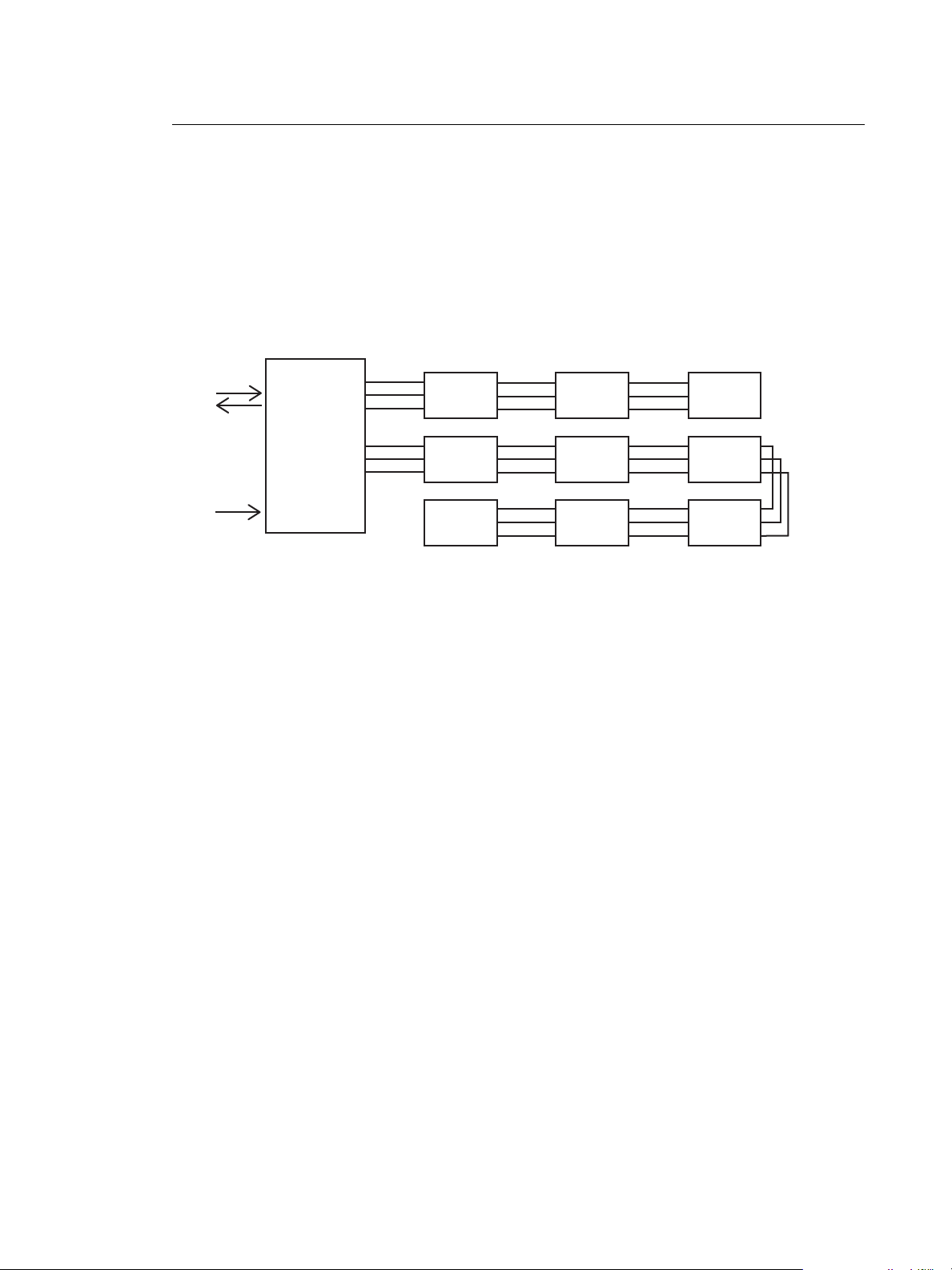
System Overview
BluesSystem is comprised of BlueDome or BlueBeam fixtures and a One-Zone or Six-Zone LV
Power Supply.
The fixtures mount directly to a junction box (either flush or surface mounted are acceptable,
but not provided) and provide focused light for corridor, stairway, lobby, and backstage
applications.
One zone power supplies are available in Switched Control or DMX512 for wall mount
installation. Six zone power supplies are available for wall mount or rack mount installation.
Models are available with DMX512, Switched Control, or 0-10 VDC Control.
Control
Power
Supply
Mains Power
PWR
O/P 1
GND
CTRL
PWR
GND
O/P 2
CTRL
Do not exceed the total load of 10 units (BlueBeam and/or BlueDome) per power zone
BlueBeam BlueBeam
BlueBeam BlueBeam
PWR
BlueBeam
GND
CTRL
BlueDome
BlueDome
BlueDome
BlueBeam
This chapter introduces you to each product and provides specification details for each
BluesSystem product.
3 BluesSystem Installation Manual
Page 7
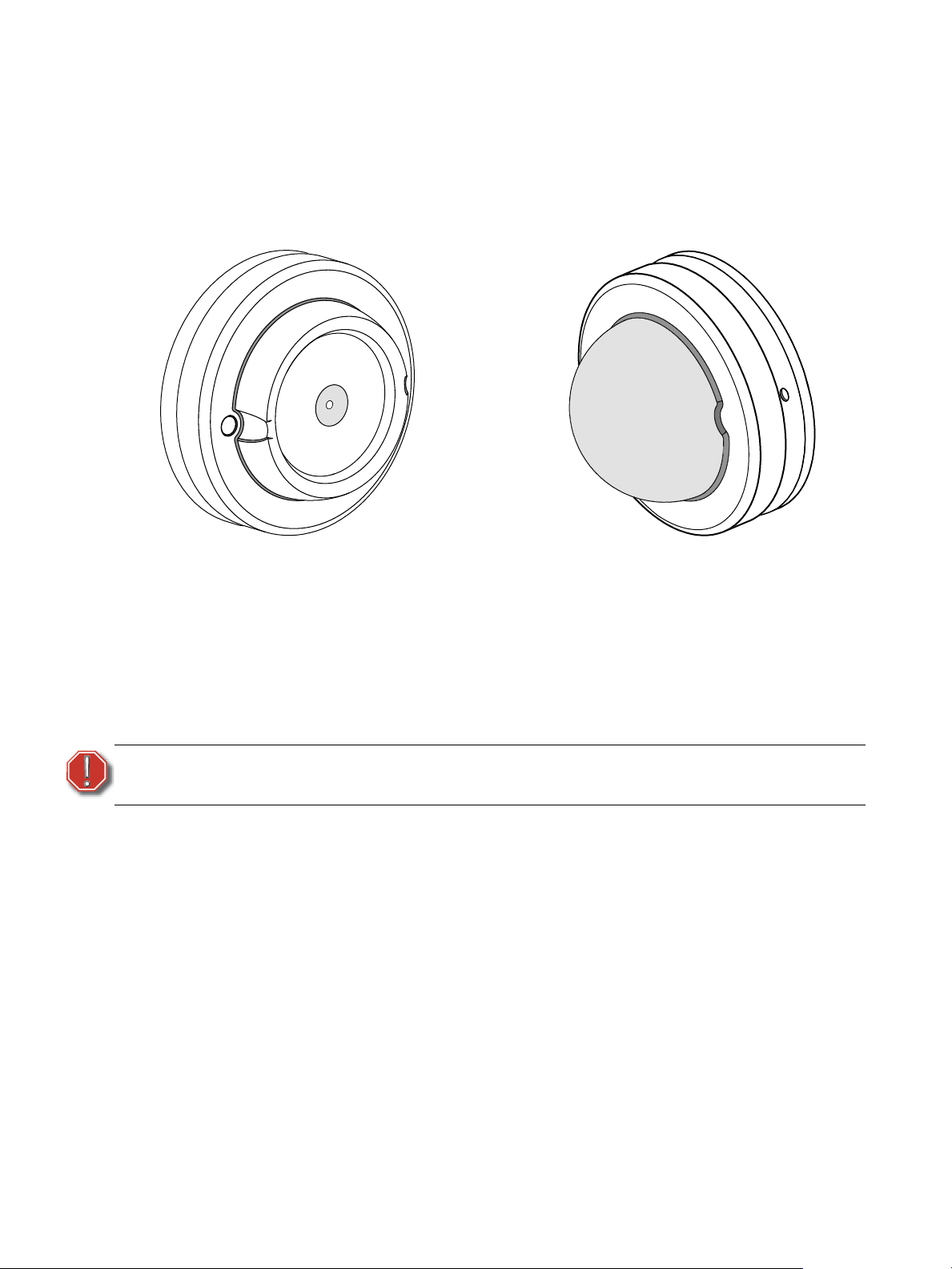
Fixtures
BlueBeam Fixture
BlueDome Fixture
Overview
Both the BlueBeam and BlueDome low-voltage LED lighting fixtures provide dimmable
running lights for tight spaces, such as catwalks, stairways, backstage areas and hallways,
that require discrete, safe illumination during live productions.
BlueBeam and BlueDome LED lighting fixtures mount directly to a standard metal or plastic
conduit junction box (either flush mounted or surface mount is acceptable). A compatible
junction box cover plate is available from ETC in either square, round, or octagonal. Contact
ETC Customer Service for ordering information.
The fixtures must be powered by a BluesSystem Low-Voltage 1 Zone or 6 Zone Power Supply.
For more information about power supplies, reference Power Supplies on page 6.
WARNING:
The BlueBeam and BlueDome LED lighting fixtures cannot be installed
in the storage area of a clothes closet.
Low-Voltage LED Fixture Electrical Specification
• Minimum operating voltage 11 VDC
• Maximum operating voltage 36 VDC
• Nominal input voltage 24 VDC
• Nominal input power 3 watts
• Operating current 125mA @ 24 VDC
• Standby current 6-8mA
• Control line impedance 100
KΩ
System Overview 4
Page 8
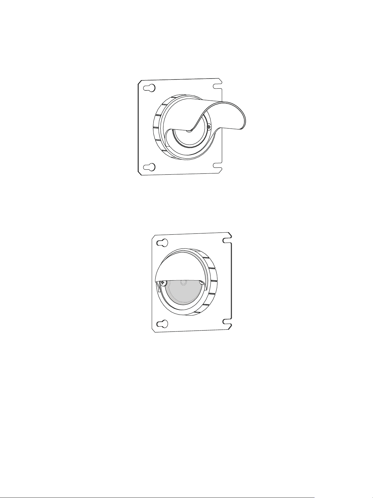
Accessories
Cowl Accessory
Eyelid Accessory
The BlueBeam low-voltage LED lighting fixture provides directional blue light and is available
in 2.5, 5, 10, 20, and 50 degree variants. The beam can be masked by using a cowl accessory.
The cowl can be rotated to mask off a selected side of the fixture beam.
The BlueDome low-voltage LED lighting fixture provides omnidirectional blue light at low
levels and is available in frosted or opaque variants. Masking can be achieved using the eyelid
accessory. The eyelid is used to mask off half of the BlueDome light output. The eyelid can be
rotated to mask off the desired portion of the light.
Both the cowl and eyelid accessories mount around the lens of the fixture using a simple push
and twist motion to lock them in place.
5 BluesSystem Installation Manual
Page 9
Power Supplies
Overview
The BluesSystem Power Supply provides power for the BlueDome and BlueBeam low-voltage
LED lights. Power supplies are available in a One-Zone and Six-Zone variants.
The One-Zone LV Power Supply provides power for up to 10 BlueBeam and BlueDome
running lights and is wall mounted. The wall mounted One-Zone LV Power Supply is available
in two models either DMX512 or Switched Control, depending on control requirements.
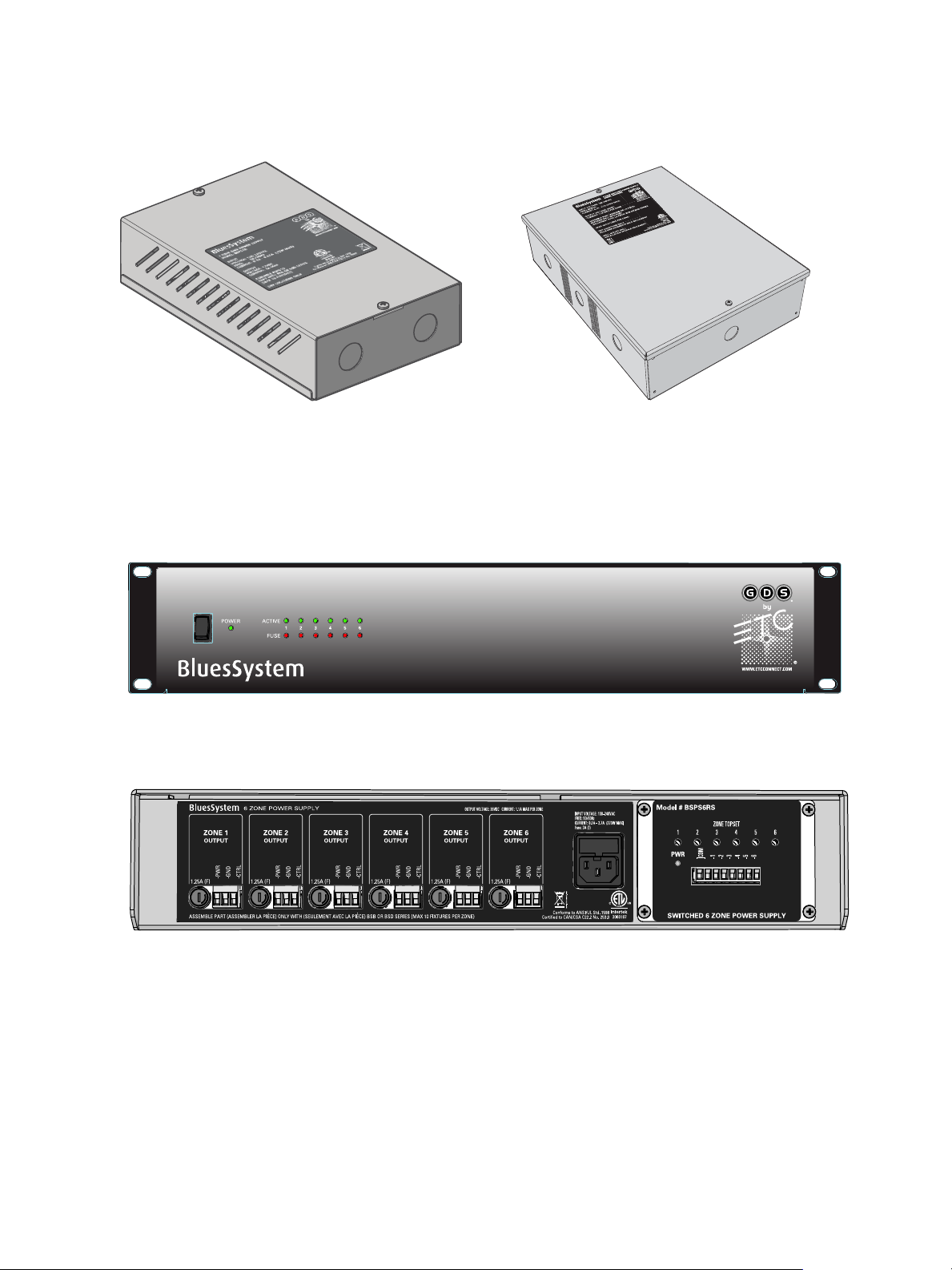
The Six-Zone LV Power Supply provides power for up to 10 BlueBeam and BlueDome running
lights per zone. Six-Zone power supplies are available in both rack mount and wall mount
variants, and offer three control options, DMX512, Switched Control, or 0-10 VDC Control.
System Overview 6
Page 10

Power Supply Electrical Specification
One-Zone LV Power Supply
• Input voltage/frequency - 100-240 VAC / 50-60 Hz
• Maximum input current - 0.65A
• Nominal output voltage - 24 VDC
• Maximum output current - 1.6A
Six-Zone LV Power Supply
• Input voltage/frequency - 100-240 VAC / 50-60 Hz
• Maximum input current - 2.7A
• Nominal output voltage - 36 VDC
• Maximum output current - 1.25A per zone
Maximum load
• One-Zone power supplies - 10 BlueBeam/BlueDome LED fixtures
• Six-Zone power supplies - 60 BlueBeam/BlueDome LED fixtures
• Control output impedance - 10 ohm
Note:
All outputs are protected from overload and short circuits by a user replaceable fuse.
Reference Fuse Replacement on page 24 for more information.
7 BluesSystem Installation Manual
Page 11

System Installation
BlueBeam Fixture
with Octagonal
Mounting Bracket
BlueDome Fixture
with Round
Mounting Bracket
This chapter details the installation and wire termination for each BluesSystem product.
Note:
WARNING:
WARNING:
Read this chapter in full before beginning your system installation.
A system without an accessible power disconnect device cannot be
serviced or operated safely. Follow all local codes and restrictions.
The BlueBeam and BlueDome LED lighting fixtures cannot be installed
in the storage area of a clothes closet.
Fixture Installation
BlueBeam and BlueDome LED lighting fixtures mount directly to a standard metal or plastic
conduit junction box (either flush mounted or surface mount is acceptable). They must be
powered by a low-voltage power supply, such as a BluesSystem One-Zone or Six-Zone Power
Supply. For more information about power supplies, reference Power Supplies on page 13.
WARNING:
• Do not connect to a mains supply. The fixture requires 11-36 VDC only.
• Do not overtighten mounting screws.
• Always use the supplied gasket.
• Do not allow moisture into rear terminal area.
ETC recommends that you install all wiring in grounded metal conduit. When calculating
cable sizes, each fixture consumes 0.13A at 24 VDC or 0.8A at 36V.
Note:
System Installation 8
All low voltage cables must run in separate conduit from higher voltage (power)
wires. Follow all local codes and restrictions.
Page 12

Supplies
The following supplies are included:
• (1) Junction box cover plate (available in round, square, or octagonal)
• (2) M4 screws for mounting the fixture to the junction box
• (1) Sealing gasket
• Wiring pigtail for power, ground, and control
The following supplies are not included (provided by others):
• Conduit and conduit fittings
• Junction box
Fixture Installation
WARNING:
RISK OF DEATH BY ELECTRIC SHOCK! Failure to disconnect all power
to the system before installation, maintenance, cleaning or any other
system modification, could result in serious injury or death.
De-energize the main feed to BluesSystem and follow appropriate
Lockout/ Tagout procedures as described in NFPA Standard 70E. It is
important to note that electrical equipment such as relay panels, can
present an arc flash safety hazard if improperly serviced. This is due
to available large short circuit currents on the feeders of the
equipment. Any work on energized equipment must comply with
OSHA Electrical Safe Working Practices.
Step 1: Install conduit between the BluesSystem power supply and the fixture installation
location, following your installation wiring plan. It is acceptable to continue the wiring
run up to 10 fixtures per zone on a power supply.
Step 2: Run wiring to the fixture, leaving approximately 8" (203mm) of wiring in the box for
future servicing as needed.
Step 3: Align the mounting plate.
Step 4: Align the provided gasket to the back side of the fixture.
Step 5: Pull wiring through the mounting plate and gasket.
9 BluesSystem Installation Manual
Page 13

Terminate Wiring
op
t
i
o
n
a
l
C
T
R
L
wi
re
pr
e-s
t
r
ipped
PWR wire
from power suppl
y
to the next f
ix
ture
Wire terminations are made to the terminals located on the back side of the fixture.
Dry Locaons Only
Note:
It is acceptable to continue the wiring run for up to 10 fixtures per zone on a power
supply.
Step 1: Locate the provided fixture termination kit.
Step 2: Connect ground.
a: Locate the pre-stripped black wire with spade terminal.
b: Loosen but do not remove the GND terminal screw on the back of the fixture.
c: Insert the spade terminal under the screw and tighten the screw firmly to secure.
d: Locate a 3 position WAGO inside the termination kit and open all terminal levers.
e: Insert the pre-stripped end of the pigtail into a terminal and close the lever.
f: Strip the ground wire from the power supply to .35-.39” (9-10mm), then insert it
into a terminal and close the lever.
g: If continuing to another fixture in the run, strip the wire .35-.39” (9-10mm) and
insert it into the third terminal and close the lever.
Step 3: Connect power.
a: Locate the pre-stripped red wire inside of the termination kit.
b: Loosen but do not remove the PWR terminal screw on the back of the fixture.
c: Insert the spade terminal under the screw and tighten the screw firmly to secure.
d: Locate a 5 position WAGO inside the termination kit and open all terminal levers.
e: Insert the pre-stripped end of the pigtail into a terminal and close the lever.
f: Strip the power wire from the power supply .35-.39” (9-10mm), then insert it into
a terminal and close the lever.
g: If continuing to another fixture in the run, strip the wire .35-.39” (9-10mm) and
insert it into the third terminal and close the lever.
System Installation 10
Page 14

Step 4: Connect control.
pre-
s
tri
pp
e
d
C
T
RL wire
f
r
o
m
power
s
u
p
p
ly
t
o
th
e
next
fixture
a: Locate the pre-stripped violet wire inside of the termination kit.
b: Loosen but do not remove the CTRL terminal screw on the back of the fixture.
c: Insert the spade terminal under the screw and tighten the screw firmly to secure.
d: Locate a 3 position WAGO inside the termination kit and open all terminal levers.
e: Insert the pre-stripped end of the pigtail into a terminal and close the lever.
f: Strip the control wire from the power supply .35-.39” (9-10mm), then insert it into
a terminal and close the lever.
g: If continuing to another fixture in the run, strip the wire .35-.39” (9-10mm) and
insert it into the third terminal and close the lever.
Step 5: Push all terminated wiring through to the junction box.
Step 6: Install the BlueBeam/BlueDome LED fixture to the installed junction box using the
provided hardware.
Maximum Cable Length Charts
One-Zone LV Power Supply at 24 VDC
AWG Max run in ft Max run with double ground
12 396 792
2.5mm
2
14 249 498
16 157 313
18 99 197
307 614
Six-Zone LV Power Supply at 36 VDC
AWG Max run in ft Max run with double ground
12 594 1188
2.5mm
2
14 374 747
16 235 470
18 148 296
460 920
11 BluesSystem Installation Manual
Page 15

Accessory Installation
BluesSystem provides the cowl and the eyelid accessory options for masking unwanted light
on the BlueBeam and the BlueDome low-voltage LED fixtures. Both accessories come with a
provided plastic accessory ring that allows the cowl or eyelid to snap onto the fixture.
Step 1: To install cowl and eyelid accessories, remove screws from the fixture.
Step 2: Align the holes on the fixture with the holes on the provided plastic accessory ring and
slide the ring down for an easy, secure fit.
Step 3: Reinstall the original screws back into the fixture.
Step 4: Snap the eyelid or cowl accessory over the plastic accessory ring.
System Installation 12
Page 16

Power Supplies
WARNING:
A system without an accessible power disconnect device cannot be
serviced or operated safely. Follow all local codes and restrictions.
BluesSystem Power Supplies are available in a One-Zone and a Six-Zone variant and provide
low voltage 24 or 36 VDC power to connected BlueBeam and BlueDome lighting fixtures.
Model Description Notes
BS-PS1-W-S Switched Power Supply Supports a maximum of 10 fixtures.
BS-PS1-W-D DMX Power Supply Supports a maximum of 10 fixtures.
BS-PS6-W
BS-PS6-R
6 Zone Power Supply,
Wall Mount
6 Zone Power Supply,
Rack Mount
Each zone supports a maximum of ten fixtures.
The 6 Zone Power Supply supports up to 60 fixtures
maximum.
Control input terminations are made inside of the power supply for the One-Zone and SixZone wall mounted versions and are continued to the lighting fixtures.
Supplies
The following supplies are required, but not provided, for installation.
• Conduit and conduit fittings.
• Phillips head screw driver.
• Four each mounting bolts or screws and wall anchors as needed. Mounting hardware must hold
at least 2.6 lbs for the one zone power supply and 8.5lbs for the six zone wall-mounted power
supply.
Wiring Requirements
Power
• Terminals accept 12 to 22 AWG
• max 0.5 Nm screw tightening torque
• wire strip length 7 to 7.5 mm
Control
Control
Type
DMX Belden 9729 (or approved equal)
Switched 12 to 30 AWG
0-10V 12 to 30 AWG
Wire Specification Notes
A 120 ohm resistor is required (not
provided) to terminate the last DMX
device in a control run.
13 BluesSystem Installation Manual
Page 17

Wall Mount Installation
Four mounting holes are provided on the rear panel of the power supply and provide for easy
mounting options.The power supply can be mounted to a wall or other smooth, supported,
vertical surface.
Step 1: Each non-vented edge of the power supply offers conduit knock outs. Knock out the
required holes based on your installation wire plan.
Step 2: Using a Phillips head screw driver, remove the two screws that secure the cover to the
power supply tray. Set screws aside for later re-installation. The cover is grounded by a
tether to the power supply enclosure.
Step 3: Align the power supply in its desired installation location and mark, then pre-drill the
four mounting holes.
Step 4: Install wall anchors (as needed) and the mounting hardware. Leave approximately 3/4”
(19mm) of the mounting hardware exposed to mount the power supply.
Step 5: Install the power supply to the mounting hardware and tighten the hardware for a
secure fit.
Rack Mounting
The BluesSystem 6 zone power supply can be ordered with rack mounted brackets for
installation into a standard 19" equipment rack.
Terminate Power Supply Wiring
WARNING:
RISK OF DEATH BY ELECTRIC SHOCK! Failure to disconnect all power
to the system before installation, maintenance, cleaning or any other
system modification, could result in serious injury or death.
De-energize the main feed to BluesSystem and follow appropriate
Lockout/Tagout procedures as described in NFPA Standard 70E. It is
important to note that electrical equipment such as relay panels, can
present an arc flash safety hazard if improperly serviced. This is due
to available large short circuit currents on the feeders of the
equipment. Any work on energized equipment must comply with
OSHA Electrical Safe Working Practices.
Mains Input Power for Wall Mounted Units
Step 1: Make sure power is off at the main breaker.
Step 2: Loosen the three screw terminals for ground, neutral, and line connections.
Step 3: Strip each wire 5/16” (7.9mm).
Step 4: Terminate the incoming ground wire (typically green/yellow) into the GROUND terminal
and tighten the screw firmly onto the wire.
Step 5: Terminate the neutral wire (typically white) into the NEUTRAL (N) terminal and tighten
the screw firmly onto the wire.
Step 6: Terminate the line (hot) wire (typically black) into the HOT (L) terminal and tighten the
screw firmly onto the wire.
System Installation 14
Page 18

Low Voltage Outputs
OUTPUT 1 OUTPUT 2
PW
R
PW
R
G
N
D
G
N
D
CTRL
CTRL
Power supply outputs (also known as Zones) can control a maximum of 10 BlueBeam or
BlueDome fixtures installed in a single wire run.
Cable Specification
Output
Term i na l s
Power
Ground
Control
30-12 AWG (.2-4mm2 solid or
.2-2.5mm2 stranded)
Wire Torq ue Notes
Supports up to 10 fixtures per
output. For the one zone power
0.5 NM
supply, the 10 fixtures can be
split between both outputs, or
utilize only one.
To connect the installed fixture(s) to the power supply Output terminals:
Step 1: Loosen the three “Output” screw terminals.
Step 2: Strip each wire to .27" (6.9mm) and label them according to the system installation
wiring plan:
• GND typically uses black
• PWR typically uses red
• CTRL when used is typically violet
Step 3: Terminate ground.
a: Terminate into the Output GND terminal.
b: Tighten the screw firmly onto the wire.
Step 4: Terminate the power wire (typically red) into the PWR terminal and tighten the screw
firmly onto the wire.
Step 5: Terminate the control wire (typically violet) into the CTRL terminal and tighten the screw
firmly onto the wire. When control is not required from the power supply, do not
terminate.
Step 6: Reference Termi n a t e W iring on page 10 for instructions to terminate wiring at the
fixture.
.
15 BluesSystem Installation Manual
Page 19

Connect Control
Power Supplies are available in DMX, 0-10 VDC control, or Switched control models.
DMX Cable Preparation
Step 1: Cut cable (if necessary) so that an
8” (20.3cm) tail extends from the edge
of the box.
Step 2: Strip 7” (17.8cm) of the outer jacket
off.
Step 3: Label the cable with the data type and
run designation. (DMX1, DMX2, etc.)
Step 4: Strip the foil shielding from each wire
set back to within 1/4” (6.3mm) of the
outer jacket.
Step 5: Untwist the shield wire from each pair
and apply a piece of 1/16” (1.5mm)
clear heat shrink to each shield wire.
Step 6: Twist each shield wire back onto its data
pair, then apply a 1.5” (38mm) piece of
3/16” (4.8mm) heat shrink all the way
down each 3-wire set. Make sure to
capture the foil shielding at the base.
Step 7: Apply the 2” (51mm) of the 3/
8” (9.5mm) heat shrink centered on the
end of the cable jacket and the bases of
all the wires in the cable.
Step 8: Cap the ends of the unused pair of wires
with a 1” (25.4mm) of 3/16” (4.8mm)
heat shrink centered over the end of the
wires.
Step 9: Strip 3/16” (4.8mm) of insulation off all
of the wires to be used.
3
D1
7
6
13
8
12
11
5
Note:
Step 10: Maintain the wire pair twist going as close to the connector as possible and terminate
Step 11: Bend back the unused set of wires.
Step 12: Secure the unused set of wires to the cable with a wire tie.
Step 13: Secure the terminated wire set(s) together with a wire tie 2” (51mm) from the
System Installation 16
In the case of two wires landing at the same terminal, strip both wires to 3/4”
(19mm), twist them together tightly and then trim them to 3/16” (4.8mm).
the wires as required.
connector.
Page 20

Terminate DMX In
Label is mounted on inside
cover of the 6 zone wallmounted power supply
Step 1: Insert the Ground (Common) wire into the Ground terminal on the DMX In connector
and tighten the screw firmly onto the wire.
Step 2: Insert the Data - wire into the Data - terminal on the DMX In connector and tighten the
screw firmly onto the wire.
Step 3: Insert the Data + wire into the Data + terminal on the DMX In connector and tighten the
screw firmly onto the wire.
DMX IN DMX THRU
Note:
Use a 120 ohm resistor (not provided) to terminate the last DMX device in a control
run.
Terminate DMX Thru
Step 1: Insert the Common wire into the Common terminal on
the DMX Thru connector and tighten the screw firmly
onto the wire.
Step 2: Insert the Data - wire into the Data - terminal on the
DMX Thru connector and tighten the screw firmly onto
the wire.
Step 3: Insert the Data + wire into the Data + terminal on the
DMX Thru connector and tighten the screw firmly onto the wire.
n
ee
Scr
n
+
-
+
a
ee
ata
ata
at
ata
Scr
D
D
D
D
17 BluesSystem Installation Manual
Page 21

Terminate Remote Switch Wiring
Ch.1
Ch.2
Ch.3
Ch.4
Ch.5
Ch.6
Ch.1
Ch.2
Ch.3
Ch.4
Ch.5
Ch.6
COM
Ch.1
Ch.2
Ch.3
Ch.4
Ch.5
Ch.6
Ch.1
Ch.2
Ch.3
Ch.4
Ch.5
Ch.6
COM
REMOTE
SWITCH
12
Note:
Switched connection requires a dry contact such as a switch or relay. Wires with
voltage present should not be landed here.
One-Zone LV Power Supply
Step 1: Insert the wire from one side of the dry contact into terminal 1 and tighten the screw
firmly onto the wire.
Step 2: Insert the wire from the other side of the dry contact into terminal 2 and tighten the
screw firmly onto the wire.
Six-Zone LV Power Supply
Step 1: Remove the connector from the unit.
Step 2: Insert the wire from one side of the dry contact into the removable connector at Ch.1
and tighten the screw firmly onto the wire.
Step 3: Insert the wire from the other side of the dry contact into the removable connector at
COM and tighten the screw firmly onto the wire.
Step 4: Repeat Steps 1-2 for all of the dry contacts.
Step 5: Install the connector into the unit.
System Installation 18
Page 22

Terminate 0-10 VDC Wiring
CAUTION:
For Sink Control
Note:
Control wires are polarity dependent. Crossing the + and – wires while
combining drivers will result in improper performance.
Sink control refers to control voltage being provided by the BluesSystem Power
Supply to the 0-10VDC controller to set the light output.
Step 1: Insert the wire from one side of the 0-10 VDC controller into the +10V terminal on the
BluesSystem power supply and tighten the screw firmly onto the wire.
Step 2: Insert the wire from the other side of the 0-10 VDC controller into the CH.1 terminal on
the BlueSystem power supply and tighten the screw firmly onto the wire.
Step 3: Repeat Steps 1 and 2 for all 0-10 VDC connections
Step 4: Set all corresponding dip switches to Sink.
For Source Control
Note:
Step 1: Insert the wire from one side of the 0-10 VDC controller into the COM terminal on the
Step 2: Insert the wire from the other side of the 0-10 VDC controller into the CH.1 terminal on
Step 3: Repeat Steps 1 and 2 for all 0-10 VDC connections
Step 4: Set all corresponding dip switches to Source.
Source control refers to control voltage being sent from the 0-10 VDC controller to
the BluesSystem Power Supply to set the light output.
BluesSystem power supply and tighten the screw firmly onto the wire.
the BluesSystem power supply and tighten the screw firmly onto the wire.
19 BluesSystem Installation Manual
Page 23

Dimming Module
BlueBeam BlueBeamBlueBeam
Mains Power
PWR
GND
PWR
GND
CTRL
PWR
GND
CTRL
Power
Supply
O/P 1
Switch
BS-DM1
Dimming
Module
BS-DM1
Dimming
Module
BS-DM1
Dimming
Module
CTRL
CTRL
CTRL
PWR
PWR
PWR PWR
GND
GND
GND
GND
CTRL
The BS-DM1 Dimmer Module is designed to allow intensity control of the BlueDome or
BlueBeam light Fittings. The Dimmer Module can be fitted anywhere in series with the
BlueDome or BlueBeam fixtures, simply connect the Dimming Module as you would connect
another Beam or Dome to the system.
Connection Examples
The schematic below shows the use of 3 BS-DM1 modules on a single power supply. This
allows individual control of each fitting.
This schematic below shows that by connecting a BS-DM1 and removing the CTRL line from
the power supply, the second set of fittings can be dimmed using the BS-DM1. These will not
be affected by the switch on the BS-PS1.
Switch
Power
Supply
Mains Power
System Installation 20
O/P 1
O/P 2
PWR
GND
CTRL
PWR
GND
PWR
BlueBeam BlueBeam
BlueBeam BlueBeam
BS-DM1
Dimming
Module
GND
CTRL
PWR
GND
CTRL
PWR
GND
CTRL
BlueDome
BlueDome
BlueDome
BlueBeam
Page 24

System Power Up and Configuration
100
10 1
DMX START ADDRESS
This chapter provides details for system power up and configuration.
Note:
WARNING:
Read this chapter in full before powering up the system.
A system without an accessible power disconnect device cannot be
serviced or operated safely. Follow all local codes and restrictions.
Configure DMX
Set the DMX Start Address
Set the DMX start address using the rotary encoders on the power supply board labeled DMX
Start Address.
The valid range is between 001 and 512 for the 1 zone power supply and between 001 and
506 for the 6 zone power supply.
DMX Loss Behavior
The DMX Power Supply has three options that can be set to change the behavior of the
output upon loss of DMX. These can be set and stored in the unit at any time during
installation or commissioning.
Step 1: To set any of the DMX Loss Behavior options, ensure the power is switched to Off and
that a DMX source is connected to the unit.
Step 2: Using the encoder wheels, set the address to any of the functions available in the table
below.
Address Function
901 Hold last look (default)
911 Channel to full on DMX loss
921 Channel fades down to 0% on DMX loss
Step 3: Switch the power on. The DMX power supply will store the new DMX Loss Behavior
operating mode in memory.
Step 4: Turn the power off and set the DMX start address for power supply operation. See Set
the DMX Start Address.
21 BluesSystem Installation Manual
Page 25

Set Minimum Level
The DMX Power Supply has the ability to set the minimum output level, which stops the DMX
signal from switching the outputs completely off.
Step 1: To set the minimum output level of the DMX Power Supply, ensure the power is
switched to Off and you have a DMX source connected to the unit.
Step 2: Set the address to 931. This will put the card into Minimum Level Capture mode.
Step 3: Set your DMX source to output 0% on DMX channel 1.
Step 4: Switch the power on. While the DMX Power Supply is in this mode, it will respond to
DMX channel 1 and output this level to the fixtures.
a: Slowly increase the DMX control level until you see the desired level, then turn the
power supply off for five seconds and then turn it on again. It will now capture the
level on DMX channel 1 and store this as the new minimum level.
Step 5: Turn the power off and set the power supply to the required DMX address.
Step 6: If a minimum level of 0% is required, set the DMX source to output 0% on channel 1
and repeat the procedure above.
System Power Up
Power Up the Power Supply
Apply power to the power supply from the main breaker. Depending on the power supply
type, the connected fixtures will respond accordingly:
• DMX power supply will turn loads on if the DMX control level is greater than 0.
• Switched power supply will turn loads on if the switch is closed.
System Power Up and Configuration 22
Page 26

Configure Switched Output Level
TOPSET
VR1
Set Output Level
A rotary potentiometer is provided on Switched power supplies to set the intensity level for
connected BlueBeam and BlueDome fixtures when the unit is switched to On.
WARNING:
Note:
Step 1: To set the output level, power the BlueBeam and BlueDome fixtures and switch the
Step 2: Use a precision screwdriver to change the rotary potentiometer (labeled TopSet) until the
RISK OF ELECTRIC SHOCK! Mains voltage is present inside the power
supply during this procedure. It is important to note that electrical
equipment can present an arc flash safety hazard if improperly
serviced. Any work on energized equipment must comply with OSHA
Electrical Safe Working Practices.
To effectively use this feature, you will need to have line of sight between power
supply and the connected fixtures.
fixtures to On.
desired intensity level on the fixtures is reached.
23 BluesSystem Installation Manual
Page 27

Fuse Replacement
WARNING:
RISK OF DEATH BY ELECTRIC SHOCK! Failure to disconnect all power
to the system before installation, maintenance, cleaning or any other
system modification, could result in serious injury or death.
Replace Input Power Fuse
The input power circuit is protected from overload and short circuits by a user replaceable
fuse.
• Replace the One-Zone LV Power Supply input fuse with a 5 x 20mm 1.25A, 250V time delay fuse.
• Replace the Six-Zone LV Power Supply input fuse with a 5 x 20mm 3A, 250V time delay fuse.
Replace Outputs Fuse
All outputs are protected from
overload and short circuits by a user
replaceable fuse.
• Replace the One-Zone LV Power
Supply output fuse with a 1.6A,
250V fuse.
• Replace the Six-Zone LV Power Supply
output fuse with a 1.25A, 250V fuse.
System Power Up and Configuration 24
Page 28

Corporate Headquarters Middleton, WI, USA Tel +608 831 4116 Service: (Americas)
London, UK Tel +44 (0)20 8896 1000 Service: (UK)
Rome, IT Tel +39 (06) 32 111 683 Service: (UK)
Holzkirchen, DE Tel +49 (80 24) 47 00-0 Service: (DE)
Hong Kong Tel +852 2799 1220 Service: (Asia)
Web:
www.etcconnect.com
7492M2100
Rev C Released 2016-03 Product information and specifications subject to change.
Copyright © 2016 ETC. All Rights Reserved.
service@etceurope.com
service@etceurope.com
techserv-hoki@etcconnect.com
service@etcasia.com
service@etcconnect.com
 Loading...