

Page 1

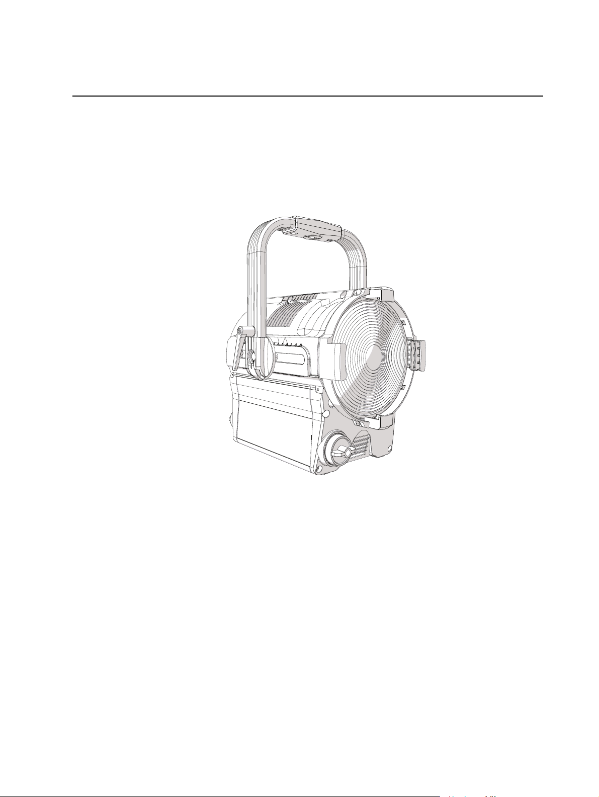
fos/4 Fresnel
User Manual
Version 1.1.1
Part Number: 7470M1200-1.1.1 Rev: A
Released: 2020-10
Page 2

To view a list of ETCtrademarks and patents, go to etcconnect.com/ip. All other trademarks, both marked
and not marked, are the property of their respective owners.
ETC intends this document, whether printed or electronic, to be provided in its entirety.
Page 3

Table of Contents
Introduction
Help from ETC Technical Services 2
Safety 3
Overview
Fixture 5
User Interface 6
Set Up and Focus the Fixture
Mount the Fixture 7
Add Accessories 7
Connect Power and Data 8
Focus the Fixture 8
Use Fixture in DMX Mode
1
5
7
9
Set DMXAddress 10
Set DMXMode 10
Set DMX Loss Behavior 12
Use Fixture in Stand-aloneMode
Studio Mode 14
Color Mode 15
Preset Mode 16
Effects Mode 17
Set Up Wireless Control
Set Up Multiverse Wireless Communication 18
Configure Fixtures Wirelessly Using the Set LightApp 18
Table of Cont ents i
13
18
Page 4

Control and Customize the Display
Lock the Display 19
Adjust the Display Settings 19
19
Troubleshooting and Maintenance
Troubleshooting Checklist 20
Test the Emitters 21
View Diagnostic Data 21
View Battery Level 22
Export Fixture Data for Troubleshooting 22
Restore Default Settings 23
Update Firmware 23
Backup and Restore the Fixture Configuration 24
Clean the Lens 24
Specifications and Reference
Environment 25
Dimensions and Weight 25
20
25
Electrical 25
RDM Parameters 26
Fixture Compliance 26
Wireless Radio Compliance 26
Licensed Software 27
ii fo s/4 F r esnel User Manual
Page 5
Introduction
•
•
The fos/4 Fresnel is a shapable wash light with top quality, highly tunable output. The fos/4
Fresne l is available in two array types:
Lustr X8: The next generation of the Lustr color syste m incorporates deep red into the
already amazing x7 mix to create an even more rich, vibra nt X8 color palette.
Da ylight HDR: Years of research resulted in an LED mix that yields the highest quality
tunable white light, optimize d for studio use.
Int roduction 1
Page 6

Help from ETC Technical Services
•
•
•
If you are having difficultie s and your proble m is not addresse d by this docume nt, try the ETC
support website at support.etcconnect.com or the main ETC website at etcconnect.com. If none
of these re sources are sufficient, contact ETC Technical Services directly at one of the offices
identified below. Emergency service is available from all ETC offices outside of normal busine ss
hours.
When calling for help, take these steps first:
Prepare a detailed description of the problem
Go ne ar the equipment for troubleshooting
Find your notification number if you have called in previously
Americas United Kingdom
ETC, Inc. ETC Ltd
Techn ical Services Department Techn ical Services Department
30 31 Pleas ant View Road 26 -28 Victoria Ind ustrial Estate
Mi ddleton, WI 5356 2 Victoria Road,
80 0-7 75-4382 (USA, toll-free) Lond on W3 6UU Engl an d
+1-608 831-41 16 +44 (0)20 8896 100 0
servi ce@etccon nect.com techs ervltd @etcconn ect.co m
Asia Germany
ETCAs ia ETC GmbH
Techn ical Services Department Techn ical Services Department
Ro om 1801, 18/F Oh mstrass e 3
Tower 1, Phas e 1 Enterprise Square 83 607 Holzkirchen, Germany
9 Sheun g Yuet Road +4 9 (80 24) 47 00-0
Kowlo on B ay, Kowl oon, Hon g Kong techs erv-germany@etcconn ect.com
+852 2799 1220
techs erv-asia@etcconn ect.com
France
ETC France
Zone Urbaparc Bâtiment E
6 Boul evard de la Libération
Saint-Deni s, 932 00
+33 1 4243 3535
techs ervltd @etcconn ect.co m
2 fo s/4 F r esnel User Manual
Page 7
Safety
•
•
•
•
•
•
•
•
•
•
•
•
•
•
•
•
IMPORTANT SAFEGUARDS
When using ele ctrical equipment, basic sa fety precautions should always be followed including
the following:
READ AND FOLLOW ALL SAFETY INSTRUCTIONS
Do not use outdoors.
Do not let power supply cords touch hot surfaces.
Do not mount nea r gas or electric heaters.
Equipment should be mounted in loca tions and at
heights where it will not readily be subjected to
tampering by unauthorized personnel.
SAVE THESE INSTRUCTIONS
Note:
only by a qualified technician. Contact ETC Customer Support for assistance .
WARNING: Note the following sa fety wa rnings before use:
The light source in this luminaire is not user-replaceable, and must be replace d
Use the fixture in dry loca tions onl y, where humidity does not exceed
90 pe rce nt (non- condensing).
Connect the fixture to a non-dimmable power source i n order to avoid
damage to the fixture 's internal power supply and other electrical
compone nts. Using a dimmable powe r source can dama ge the fix ture
and will void the warra nty.
Di sconnect the fixture from powe r and DMX and allow it to cool before
insta lling accessories or performing any cleaning and maintena nce .
Only use mounting hardwa re that is rate d for the tota l weight of the
fixture and accessories.
In addition to primary suspension, atta ch a sa fety cable ( or othe r
approved safe ty device ) to the fixture. Safe ty ca bles must be ra ted to
support ten times the fixture weight. Consult loca l standards to ensure
tha t sa fety cables mee t all requirements. See
page 7
.
Che ck that the acce ssory holder is locked and that any a ccessory sa fety
ca ble s are connected before mounting the fi xture.
Do not mount the fixture on or near a flammable surface.
Do not ope rate the fixture without the lens installe d.
Do not use this fixture with a da mage d power lead. If the powe r lead
(cord set) is damaged, it must be re place d.
Do not use this fixture if the le ns is deepl y scratched or cra cked. You
must replace the lens when it is damaged.
The use of accessory equipment not
recommended by the manufacturer
may cause a n unsafe condition.
Do not use this equipment for other
than intended use.
Mount the Fixture on
Int roduction 3
Page 8

AVERTISSEMENT : Prendre connaissa nce des av e rtisse ments de sé curité
•
•
•
•
•
•
•
•
suivants avant toute utilisation :
Dé bra nchez le projecteur de son alimentation et du DMX et laissez-le
refroidir ava nt d’installer des accessoires ou d’effe ctue r un nettoya ge
ou un entretien.
N’ utilise z que de la quincaillerie de montage a dapté e au poids total
des proje cte urs et des accessoires.
En plus de la suspension principale , fixez une cha îne de sé curité (ou
tout autre dispositif de sécurité homologué) au proje cte ur. L e s chaînes
de sécurité doivent être en mesure de supporter dix fois le poids du
proje cte ur. Consultez les normes loca le s pour vous assure r que les
câ ble s de sécurité respe cte nt toutes les exigences.
Vé rifie z que le porte-accessoires est verrouillé et que les élingues de
tous les accessoires sont bie n attachées ava nt de monter le projecteur.
Ne pas insta ller le projecteur sur ou à côté d’une surface inflammable.
N’ utilise z pas le projecteur sans que la lentille soit insta llée.
Ne pas utiliser ce projecteur avec un cordon d’alimentation
endommagé . Si le cordon d’alimentation (câ ble) e st abîmé, il doit être
remplacé .
N’ utilise z pas ce projecteur si la lentille prése nte des rayures ou des
fissures profondes. Il faut remplace r la lentille si elle est abîmée.
4 fo s/4 F r esnel User Manual
Page 9
Overview
A
D
G
F
E
I
J
K
H
A
B
D
C
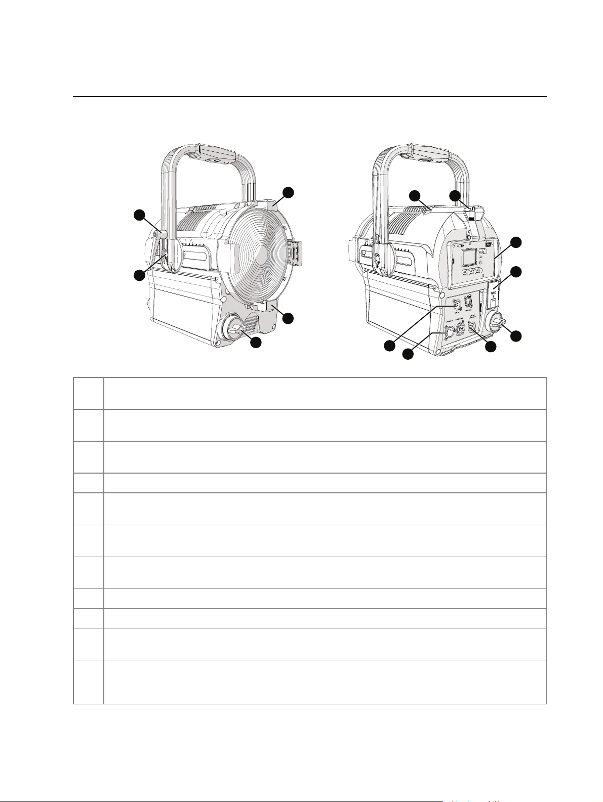
Fixture
Accessory holde r:
A
and then lock the holder. S ee
Yok e tilt-lock:
B
Insert accessories into the two available slots from either side of the holder,
Add Accessories on page7
.
Tilt the fixture as needed, and then turn the tilt-lock clockwise to lock the
position. If necessary, press the center button on the tilt-lock to adjust the tilt-lock position.
Adjusta ble yoke:
C
neede d to balance the fixture . Tighten the bolts to secure. See
Zoom knob:
D
NFC(Near Fie ld Communica tion) tag: Use the
E
with or without power applied to the fixture . See
User inte rface:
F
Loosen the bolts, and then shift the adjustable yoke forwa rd or backwa rd as
Add Accessories on page7
Rotate the zoom knob on either side of the fixture to adjust from spot to flood.
Se t Light
Se t Up Wireless Control on page18
app to wirelessly configure the fixture,
.
View the fixture status, set the DMXaddress and mode, or set sta nd-alone
.
options.
Antenna : For use whe n controlling the fixture using wireless DMX. See
G
on page18
Safety cable atta chment point:
H
DM X In a nd DMX Thru connectors:
I
Powe r In a nd Powe r Thru connectors:
J
power thru.
Batte ry connector: Three-pin XLRconne ctor for battery power.
K
power only when AC power is not available. Maximum fixture output may be reduced when
.
Se e
Mount the Fixture on page 7
Five-pin XLRconnectors for DMX/RDM in and thru.
powerCO N®TRUE1 TOP conne ctors for power in and
Conne ct the fixture to battery
Se t Up Wireless Control
.
powered by battery.
Ov erview 5
Page 10
User Interface
Effects
Effect Flicker
Rate 200
Min 0%
Max Int 100%
DMX
B
A
E
F
G
C
D
•
•
•
•
•
•
•
•
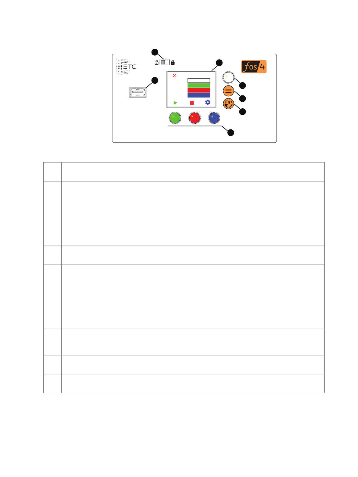
Display:
A
display (E) and the Intensity encoder to the right of the display(B).
The colors of options on the display correspond to the colors of the encoders below the
B Intensity e ncoder
:
When in DMX mode, press the Intensity encode r to enter Focus mode when focusing the
fixture.
When configuring the fixture in one of the stand-alone modes, press the Intensity encoder to
toggle between the current intensity and 0, or turn the Intensity encoder to modify the white
fields on the display. See
Use Fixture in Stand-aloneMode on page13
.
When navigating from the Main Menu scre en, turn the Intensity encoder to scroll through
menu options, and then press the Intensity encoder to select a menu option.
Me nu button:
C
Press to view the Main Menu screen and configure the fixture. Press the button
again to return to the previous screen when you are setting configura tion options.
Function button: Press repeatedly to toggle through the following modes:
D
Studio: Use one of three studio (white light) prese ts, or customize the presets.
Color: Use one of 12 color presets, or customize the prese ts.
Preset: Use one of 12 presets ( color pre set + fade time), or customize the presets.
Effects: Use one of 12 effects, or customize the effects.
DMX: View and set DMX parameters for the fixture .
Se e
Use Fixture in Stand-aloneMode on page13
Encoders(Red, Gre e n, Blue):
E
The colors of encode rs correspond to options on the display.
and
Use Fixture in DMX Mode on page9
Press to activate the options at the bottom of the display, or turn to modify the values on the
display.
US B port:
F
saving error logs via a flash drive.
Use for updating firmware, saving and loading fixture configuration se ttings, or
Se e
Troubleshooting and Maintenance on pa ge20
.
.
UI lock :
G
6 fo s/4 F r esnel User Manual
Display on page19
Se t this switch to lock the UI. This preve nts inadverte nt changes to the UI.
.
Se e
Lock the
Page 11

Set Up and Focus the Fixture
•
•
•
•
•
•
B
A
D
C
C
WARNING: Note the following sa fety wa rnings before use:
Only use mounting hardwa re that is rate d for the tota l weight of the
fixture and accessories.
In addition to primary suspension, atta ch a sa fety cable ( or othe r
approved safe ty device ) to the fixture. Safe ty ca bles must be ra ted to
support ten times the fixture weight. Consult loca l standards to ensure
tha t sa fety cables mee t all requirements. See
Che ck that the acce ssory holder is locked and that any a ccessory sa fety
ca ble s are connected before mounting the fi xture.
AVERTISSEMENT : Prendre connaissa nce des av e rtisse ments de sé curité
suivants avant toute utilisation :
N’ utilise z que de la quincaillerie de montage a dapté e au poids total
des proje cte urs et des accessoires.
En plus de la suspension principale , fixez une cha îne de sé curité (ou
tout autre dispositif de sécurité homologué) au proje cte ur. L e s chaînes
de sécurité doivent être en mesure de supporter dix fois le poids du
proje cte ur. Consultez les normes loca le s pour vous assure r que les
câ ble s de sécurité respe cte nt toutes les exigences.
Vé rifie z que le porte-accessoires est verrouillé et que les élingues de
tous les accessoires sont bie n attachées ava nt de monter le projecteur.
Mount the Fixture be low
.
Mount the Fixture
You ca n mount the fixture using a clamp, baby-pin (16mm)
receiver, or spigot on the yoke(A), or you can set the fixture on the
floor or another fla t surface. When suspending the fixture, make
sure to secure the fixture with an appropria te safety cable at the
safety cable attachment point (B).
If nece ssary, move the adjustable yoke (D in image below) to
balance the fixture. Use a 13 mm socket wrench to loosen the bolt
and shift the yoke position, a nd then tighten the bolt to secure the
yoke.
Add Accessories
You ca n use up to two standard accessories (one scrim
and one additional a ccessory, such as a barn door) in the
accessory holder.
1. Unlock the acce ssory holder on either side by
pressing the spring-release a nd rotating the
accessory holder lock (C).
2. Slide an accessory into one of the accessory slots.
Add a second accessory in the other slot, if needed.
3. Lock the accessory holder by rotating the accessory
holde r lock back into place.
4. If necessary, move the adjustable yoke (D) to
balance the fixture when using heavier accessorie s.
Set Up and Focus the Fixt ure 7
Page 12

Connect Power and Data
•
•
•
•
•
•
•
1. Attach five-pin XLR cable to the
DMX In connector (if using
external control).
2. Plug the XLR cable (if using) into
the DMX source or data daisychain.
3. Use the DMX T hru connectors to
conne ct up to 32 device loads on
the DMX daisy chain.
4. Are you using AC power or
battery power?
AC power: Continue to step5.
Battery power:Continue to
step6.
5. Use the Power Thru connectors
to connect other fixtures using
the following recomme nde d
guide lines, and the n continue to ste p 6:
Power Thru: Link up to 6 additional fixtures ( 12A max) via Power Thru connector
when using an R20 Rela y Module (consult breaker-trip curves when using othe r
equipment).
6. Supply power to the fixture in one of these ways:
Attach the power cable to the Power In connector, and the n plug the power cable into
AC power (100–240VAC, 50/60 Hz) on a non-dimmable circuit.
Attach the thre e-pin XLR cable to the Battery connector, and then plug the cable into
the ba ttery (24–36VDC). Cable must be rated for 10A or greater.
CAUTION:
Do not connect the fixture to the battery when AC power is
present. Maximum fixture output may be reduced when the fixture is
connected to battery power.
Focus the Fixture
1. Apply power to the fixture, and wait until the fixture has booted up(the ETC splash screen
displays during boot up).
2. Press any encoder to "wake" the display.
3. What screen is currently displayed?
DM X:Press the Intensity encoder to turn on the LED array. The display shows a
timeout countdown to indicate how long the LED array will remain on at 100%
intensity. You can turn the Intensity encoder to reset the time out countdown to
5minutes.
All othe r screens (S tudio, Prese t, e tc. ) : Press the Intensity encoder to turn on the
LEDarray, and turn the Intensity encoder to adjust the intensity.
4. Adjust the fixture to the desired position.
5. Rotate the zoom knob on eithe r side of the fixture to adjust from spot to flood.
6. Press the Intensity encode r to turn off the LEDarray.
8 fo s/4 F r esnel User Manual
Page 13

Use Fixture in DMX Mode
DMX
Address
Mode
DMX Loss
1/3 Red
DMX
Address
Mode
DMX Loss
1/3 Red
001
3 Ch RGB
HLL
001
3 Ch RGB
HLL 2 Min
Press any encoder to wake the display... ...and then turn an encoder to modify the value in
the matching field. Press an encoder again to save
the value and return to the view-only screen.
•
•
•
After you connect power and data to the fixture and provide DMX, press the Function button ( )
repeatedly to toggle to the DMX screen, where you can set the DMX address, DMXmode, a nd
DMXloss behavior. (You can also set these values using RDM.)
The DMX screen displays the current DMX values. Press any of the encoders to "wake" the
display and edit the values. The colors of the encoders correspond to options on the display.
Turn an encoder to modify the corresponding value, and then press the encode r to save the new
value.
After you wake the display, you can press the Intensity encoder to enter Focus mode. See
the Fixture on the previous page
Note:
If the colors on the display or on the encoders are difficult to discern, you can
.
navigate based on position rather than color:
Top value = Left encoder
Middle value = Center encoder
Bottom value = Right encoder
Focus
Use Fixt ure in DMX Mode 9
Page 14

Set DMXAddress
•
•
•
•
•
In the DMX screen, turn the green encode r to set the DMX address. The default addre ss is 001.
Set DMXMode
In the DMX screen, turn the blue e ncoder to set the DMX mode.
Direct: Direct control of emitters.
Expanded: Combines RGBcontrol with Studio control. The Mix control channel in
Expanded mode move s control from full RGB mode to full Studio mode.
Studio: CCT (Correlated Color Te mperature) control, Tint control (from -10 to 10 green),
and Tuning control ranging from Brightest to Spectral. This is the default mode for
Daylight HDRfixtures.
3 Ch RGB: S tandard RGB control. In RGB mode, the Curve is always se t to Incandescent
and the Fan is always set to Auto. This is the de fault mode for Lustr X8 fixtures.
1 Channel: Intensity control for prese t 1. (See
mode, the Curve is always set to Incandesce nt and the Fan is always set to Auto.
DMXModes
Preset Mode on page 16
.) In 1 Cha nne l
RDMPersonality ID
Direct
(Day lightHDR)
1 1 2 3 4 5
Direct
(Lust r X8)
Expanded Studio 3 Ch RGB 1 Channel
DMXChannel
1 Int ensity Int ensity Int ensity Intensit y Red Int ensity
2 Deep Red Deep Red CCT
3 Red Red Tint
4 Mint Amber Tuning
5 Cyan Lime Mix
*
*
*
*
6 Blue G reen Red Curve
7 Indigo Cyan Gr een Fan
8 Strobe
9 Cur ve
10 Fan
11 Cur ve
12 Fan
* See
DMX Control Channels below
*
*
*
Blue Blue
Indigo Str obe
*
Strobe
*
*
Cur ve
*
Fan
fo r the DMX values that set these parameters.
*
*
DMX Control Channels
Paramet er DMX V alue Description Comments
CCT 0 3200K
1–165 1900 –60 00K CCTvalu es increase by 2 5 for each DMX v alue
166–254 6050–10,450K CCTvalues incr ease by 50 f or each DMX v alue
255 5600K
(1=1900K, 2 =1925K, etc.).
(166=6050K, 167 =6100K, etc.).
*
CCT
*
Tint
Tuning
Strobe
*
Gr een
Blue
*
*
*
10 fo s/4 F r esnel User Manual
Page 15

Paramet er DMX V alue Description Comments
Cur ve 0–9 Incandescent
10–19 Linear
20–29 Incandescent Red Shift In Direct Mode, the fixt ure uses In candescent inst ead of
30–39 Linear Red Shif t In Dir ect Mode, the f ixtu re uses Linear inst ead of Linear
40–255 Reser v ed All m odes use Inc andesc ent in the range of DMXvalues
Fan 0–9 Auto
10–19 Off Wh en the fixtu re gets t oo hot, the f ixture r educes t he
20 Slow Minimum fan speed
21–248 Linear Increase in Speed
249 Fast Maximum fan speed (100% )
250–255 Aut o
Mix 0 Full St udio
1–254 Linear int er polat ion fr om
255 Full RGB
Strobe 0 No Strobe Shutt er open
1–40 Dark Strobe Range is 1–40Hz.
41–80 Bright Strobe Range is 1–40Hz.
81–120 Pulse Strobe Strobe includes a f ade up and f ade down on each pulse.
121–160 Random Str obe Strobe pulses at r andom int ervals.
161–200 Flic ker Eff ect Str obe p ulses at random interv als and at random
201–240 No Strobe Shutt er open
241–254 LEDs O ff Shutt er clo sed
255 No Strobe Shutt er open
Tint 0 Neut r al
1–127 Linear bet ween +1 0 and 0 Tint shif t s towar d green (+10) as t he DMX value
128 Neut r al
129–255 Linear between 0 and - 10 Tint shif t s towar d magenta (- 10) as the DMX value
Tuning
(Color
calc ulation
met ho d)
0–49 Brig ht est Calculation uses a combinatio n of LEDs to produce t he
50–99 Hy brid Calculat ion is halfway bet ween t he bright est and t he
100–149 Spectral Calculat ion u ses a combinat ion of L EDs to pr oduce the
150–255 Reser v ed This range is r eser ved for f uture developm ent , but
Studio to RGB
Incandescent Red Shift.
Red Shift.
fo r Reser ved.
int ensity instead of turn ing on the fan.
int ensity levels.
decreases to 1.
increases to 255.
br ightest v ersion o f t he selec t ed chromaticit y.
best spect r al m atch o f t he selec t ed chr omaticit y .
best spect r al m atch o f t he selec t ed chr omaticit y . The
Spectral op tion r esults in higher color r end ering, but
lower int ensity levels.
currently outputs t he Br ight est color calculation
met ho d.
Use Fixt ure in DMX Mode 11
Page 16

Set DMX Loss Behavior
•
•
•
•
In the DMX screen, turn the red encoder to set the DMX loss behavior. Options are:
Instant: Immediately return to last look used in stand-alone mode. If no stand-alone look
was selected, the fixture goes dark.
HLL 2min:Hold last look for two minutes or until you mak e local changes. If you make no
changes during the two minutes, the fixture fades out over two seconds.
HLL:Hold la st look until you make local changes. This is the default se tting.
Preset 12: Two-second fade from last look to Preset 12.
12 fo s/4 F r esnel User Manual
Page 17

Use Fixture in Stand-aloneMode
•
•
•
•
•
•
•
-
-
-
•
-
-
-
After you connect power to the fixture, press the Function button ( ) repeatedly to toggle
through the following modes:
Studio: Use one of three studio (white light) prese ts, or customize the presets.
Color: Use one of 12 color presets, or customize the presets.
Preset: Use one of 12 presets (color prese t + fade time), or customize the pre sets.
Effects: Use one of 12 effects, or customize the effects.
DMX: View and set DMX parameters for the fixture.
The colors of options on the display correspond to the colors of the encoders below the display
and the Intensity encoder to the right of the display. Turn an encode r to modify the
corresponding value on the display, or press an encoder to activate the corresponding option at
the bottom of the display. Press the Intensity encoder to toggle between the current intensity
and 0%.
If the fixture is connected to other fos/4 Fresnel fixtures that are in the sa me stand-alone mode,
the connected fixtures will play the same preset or effect.
If the fixture is receiving DMX, the DMXdata overrides any stand-alone mode selections. When
the fixture is no longer receiving DMX, then the stand-alone selections take effect the next time
you interact with the user inferface .
Note:
If the colors on the display or on the encoders are difficult to discern, you can
navigate based on position rather than color:
Intensity = Intensity encoder
From top to bottom (in main section of display):
Top value = Left encoder
Middle value = Center encoder
Bottom value = Right e ncoder
From left to right (at bottom of display):
Left value = Left encode r
Center value = Center encoder
Right value = Right encoder
Use Fix t ur e in Stand-aloneMode 13
Page 18

Studio Mode
Studio
3200K 4500K 5600K
CCT 3200 K
Tint 0.0 Green
Tune Brightest
Int 100%
Studio
3200K 4500K 5600K
CCT 3125 K
Tint 0.0 Green
Tune Brightest
Int 100%
Press an encoder to play that
studio preset...
...or turn an encoder to modify the
value in the matching field.
Turn to adjust intensity, or press to
toggle between current intensity and 0.
DMX
DMX
•
•
•
•
•
•
•
1. Press the Function button ( ) until the display shows the Studio screen.
2. Press the color encoder that ma tches the studio preset you want to use.
Blue: 3200K
Green: 4500K
Red: 5600K
More Opti ons
Turn off the preset: Pre ss the Intensity encoder to toggle the intensity value from the
current value to 0. Press the Intensity e ncoder again to toggle back to the previous
intensity value.
Modify the preset:Turn the encoders to change the corresponding values. For example,
turn the Intensity encoder to change the intensity va lue, or turn the blue encoder to
change the color tempera ture value.
Revert to the original prese t:Press the encoder that corresponds to the preset again to
restore the original values.
Save the modified preset:Press and hold the encoder that corresponds to the preset that
you want to re-record. The display shows a three-second countdown before re -re cording
the preset.
Note:
DMX mode is set to Studio. See DMX Control Channels on page10.
The CCT, Tint, and Tune values match the values that are availa ble when the
14 fo s/4 F r esnel User Manual
Page 19

Color Mode
Color
P1 P2
20
29
H: S: I: 97%
Page 1
Color
P3 P4
20
29
H: S: I: 97%
Page 2
Press and hold an encoder to
record the color to that preset.
Turn the green or blue encoder to
modify the value in the matching field.
Turn the red encoder to move
to another page of presets.
Turn to adjust intensity, or press to
toggle between current intensity and 0.
DMX
DMX
•
•
•
1. Press the Function button ( ) until the display shows the Color screen.
2. Turn the encoders to change the corresponding values. For example, turn the Intensity
encoder to cha nge the intensity value, or turn the gree n encoder to change the hue value.
The crossha irs on the display indicate the approximate color.
You ca n use a preset as a starting point for a color by pressing the color encoder that
matches the preset. Turn the red encoder to move to another page of presets.
More Opti ons
Number Pr eset
1 3200K
2 4500K
3 5600K
4 Yellow
5 Dark St raw
6 Red
Number Preset
7 Medium Pink
8 Magent a
9 Medium Blue
10 Pr imary Blue
11 Blue Gr een
12 Green
Turn off the color: Press the Intensity encoder to toggle the intensity value from the
current value to 0. Press the Intensity e ncoder again to toggle back to the previous
intensity value.
Revert to the original color of a preset: Press the encoder that corresponds to the preset
again to restore the origina l values.
Save the color to a preset:Press and hold the encoder that corresponds to the preset that
you want to re-record. The display shows a three-second countdown before re -re cording
the preset. Changes that you mak e to prese ts in the Color screen also affect pre sets in the
Effects screen and the Preset screen.
Use Fix t ur e in Stand-aloneMode 15
Page 20

Preset Mode
Edit Preset Color 4
100%
215
39H: S: I:
100%
Preset
Preset 4
Fade 3 seconds
Int 100%
Yellow
Press to
play/pause
the preset.
Turn an encoder to modify the
value in the matching field.
Press to
stop the
preset.
Press to modify the
preset color, or hold
to capture DMX.
Press to return
to the Preset
screen.
The background approximates
the preset color.
Press to
save the
new color.
DMX
•
•
•
•
•
•
1. Press the Function button ( ) until the display shows the Preset screen.
2. Turn the green encoder to select a prese t, and then press the encoder to pla y the preset.
Number Pr eset
1 3200K
2 4500K
3 5600K
4 Yellow
5 Dark St raw
6 Red
Number Preset
7 Medium Pink
8 Magent a
9 Medium Blue
10 Pr imary Blue
11 Blue Gr een
12 Green
More Opti ons
Pause the preset fade: Press the green encoder to toggle between pla y and pause.
Stop the preset: Press the red encoder.
Modify the preset:Turn the Intensity encoder to change the intensity, or turn the red
encoder to cha nge the fade value .
Ca pture the current DMX look: Pre ss and hold the blue e ncoder (for the Sna pshot icon ).
The display shows a 3-second countdown before re-recording the preset. Capture is
limited to thre e DMX modes: 3 Ch RGB, Studio, and Expanded.
Modify the preset color:Press the blue e ncoder (for the Edit icon ). In the Edit Preset
Color scree n, turn the encoders to change the corresponding values. The crosshairs on the
display indicate the approximate color. Press the green encoder (for the Save icon ) to
save the new color to the preset.
Push the prese t to connected fixtures:Press the Menu button ( ), and then use the
Intensity encoder to naviga te through the menu: Local Settings>Push Presets. Whe n the
screen prompts you to confirm, press the green encoder (for the O K icon ) to continue .
Note:
Changes tha t you make to pre sets in the Preset screen also affect prese ts in
the Color screen and the Effects screen.
16 fo s/4 F r esnel User Manual
Page 21

Effects Mode
Effects
Effect TV Set
Rate 250
Min 0%
Max Int 100%
Settings
Style Custom
Step 1
Preset 1
Max Int 100%
Turn to select effect,
and then press to
play/pause the effect.
Turn to modify
the value in the
matching field.
Press to
stop the
effect.
Press to
modify the
effect.
Press to return
to the Effects
screen.
Turn an encoder to modify the
value in the matching field.
DMX
DMX
•
•
•
•
1. Press the Function button ( ) until the display shows the Effects screen.
2. Turn the green encoder to select an effect, and then press the encoder to play the effect.
Effec t Description
Flic ker Fire or candle
Siren Police or emergency v ehicle lights
Light ning L ightning strikes
Beacon Rhy thmic flashing
TV Set Flic ker ing t elev ision screen
Projector Flic ker ing f ilm projector
Effec t Descrip tion
Camera Paparazz i f lashbulbs
Elect r ical Occ asional inc reases in inten sit y
Party Rhythmic pulsing with bumps thr ough c olors
Fir eworks Bur st s in random colors t hat fade
Explosion Burst s in a select ed color t hat fade
Sequence Series of presets
More Opti ons
Pause the effect: Pre ss the green encoder again. The green encoder toggles between play
and pause. Whe n you press the gree n encoder to play the effect again, the fixture
resumes the effect from where you paused it.
Stop the effe ct:Press the red encoder. When you press the green encoder to play the
effect again, the fixture plays the effect from the be ginning.
Modify the effect:Turn the encoders to change the corresponding value s. To modify the
effect further, press the blue e ncoder (for the Settings icon ) to modify the settings for
the effect.
Push the effect to connecte d fixture s:Press the Menu button ( ), and then use the
Intensity encoder to naviga te through the menu: Local Settings>Push Effects. W hen the
screen prompts you to confirm, press the green encoder (for the O K icon ) to continue .
Use Fix t ur e in Stand-aloneMode 17
Page 22

Set Up Wireless Control
Set Up Multiverse Wireless Communication
You ca n use a City Theatrical Multiverse®transmitting device to wirelessly configure and control
the fixture. For information on using Multive rse products, see the documentation provided with
the products.
Note:
wireless system, download the Wireless Fixture Setup Information Guide at
etcconnect.com.
To use Multiverse wireless communication, configure the Multiverse settings on the fixture.
1. Press the Menu button ( ), turn the Intensity encoder to naviga te to Multiverse Settings,
and then press the Intensity encode r to select it.
2. Turn the Intensity encoder to set the Universe value.
3. Turn the green encoder to enter the SHoW ID value. T his va lue must ma tch the S HoW ID
value on the Multiverse transmitting device .
4. Turn the blue encoder to enter the SHoW Key value. This value must match the SHoW Key
value on the Multiverse transmitting device .
5. Turn the red encoder to se t the Powe r value. This va lue sets the power level of the
wireless transmitter on the fixture. Set the value to the minimum level required for
successful communication between tra nsmitters a nd fixtures. Excess power output can
cause reflections and can degrade performance.
6. Press the green encoder for the Save button ( ) to save your settings, or press the red
encoder for the Cancel button ( ) to discard your cha nges.
For additiona l guidance and troubleshooting resources when setting up your
Configure Fixtures Wirelessly Using the Set LightApp
Download the Set Light app to a smartphone with NFC functionality, use the app to set fixture
parameters, and then tap the smartphone to the NFC tag on the fixture to configure it
wirelessly—even when the fixture is not powered on. Or, after you configure the Multive rse
settings on the fixture, use the Set Light app to configure one fixture or multiple fixtures
wirelessly from a smartphone or ta blet. (You must be within Bluetooth range of the Multiverse
transmitter or gateway in order to use the app in this mode.) Visit etcconnect.com/Apps for
more information about the S et Light app.
18 fo s/4 F r esnel User Manual
Page 23

Control and Customize the Display
Effects
Effect Flicker
Rate 200
Min 0%
Max Int 100%
DMX
UI Lock
•
•
•
•
•
Lock the Display
Se t this switch to lock the UI and prevent
any change s to the fixture setup. The
display indicates when the UI is locked.
Adjust the Display Settings
1. Press the Menu button ( ), turn
the Intensity encoder to navigate to
Local Settings, and then press the
Intensity encoder to select it.
2. In the Local Settings screen, turn
the Intensity encoder to se lect the
display parameter that you want to modify, and then press the Intensity encoder to modify
it.
3. Turn the Intensity encoder to modify the value of the parame ter, and then press the
Intensity encoder to save the value.
4. Press the Menu button ( ) or press the red encoder until you return to the Main Menu
screen when you are done.
Paramet er Description
Backlight Set the display backlight from 10–100% .
Timeout Set t he t ime t hat the display will remain illu min ated after the last time you pr ess an
encoder or button. O ptions ar e:
Never (d isplay is always illuminated)
30 sec onds
1 minut e (def ault)
5 minut es
15 minutes
Contro l and Customize the Display 19
Page 24

Troubleshooting and Maintenance
•
•
•
•
•
•
•
•
•
•
•
•
•
•
•
•
•
•
•
•
•
•
Troubleshooting Checklist
If you cannot find the resources that you need in this document, contact ETC Technical Service s
(see
Help from ETC Technical Services on page2
What I'm Seeing What Might Be Wrong What To Tr y
Color on the f ix tur e does
not mat c h ano ther fixt ure,
or c olor on the fixt ure
does not mat ch expected
color outp ut
Error message "Array
Comm" or "Array Failure"
displays on screen
Error message "Color Data
Fail"displays on screen
Error message "LED High
Temp" or "Power
Budgeting" displays on
screen
Error message "Low
Bat tery" displays on
screen
Error message
"Mult iv erse Failu re"
displays on screen
Fix tur e is not
responding to wireless
cont rol
Fix tur e is r esp onding
int ermit t ent ly to
wireless cont r ol
Error message "No
Bundle" displays on scr een
Error message "USB Error "
displays on screen
Fan is loud DMXvalue for fan o per at ion is set too high. Verify that t he DMX value is appr opr iate f or the fan
Fix tur e is f lickering Fixture is receiving bad DMX . Chec k the About Contr ol sc reen to verif y t hat t he
Fix tur e is stuck on t he last
look sent via DMX
Color is out-of-gamut (er ror message
displays).
Temperatu re sensor is failing.
Fix tur e cannot communicate wit h the
LEDarray.
Fix tur e cannot load its c olor informat ion. Contact ETC Technical Services.
Fan is set to a lev el t hat is too low f or the
current LED int ensity.
Fan has failed.
Temperatu re sensor is failing.
Fix tur e is power ed by a b attery , and th e
bat tery level is low.
Fix tur e is still connected to wired DMX
cont rol (v ia DMX In connector). Wired
DMX data takes pr ecedence ov er wireless
DMXdata.
Ot her wir eless sy st ems ar e int er fering wit h
th e Multiver se wir eless communication.
Fix tur e ant ennas or Mult iverse produ ct
ant enn as are not o rient ed optimally.
Multiverse t ransmitter is not locat ed
optimally.
Fix tur e does not have a firmwar e bundle
stor ed inter nally. Th is may indicat e that a
fir mware update failed.
Fix tur e cannot r ead the USB f lash d rive. Remov e and t hen r e- insert the USB f lash d rive. If the
The fixt ure may not be r eceiving DMX. (If yo u
have not changed the DMX L oss behav ior,
th e default set ting is HL L, which causes the
fix t ur e to hold t he last look unt il you make
local c hanges.)
).
Sending an out -of -gamut co lor to a f ixture c an
result in dif f erenc es in color output. Check t he
About Color scr een t o see if t he color is out-o fgamut . See
page
If the temperature sensor is failing, cont act
ETCTechnical Ser v ices f or assistance.
Contact ETCTech nic al Servic es.
Verif y whether the fan is r unning. Check t he
About Sensors screen to v iew the current f an
level. See
page
If the temperature sensor is failing, cont act
ETCTechnical Ser v ices f or assistance.
Connec t t he f ixture t o a fr esh b attery . Follow t he
inst r uc t ions prov ided with t he batt er y t o r echar ge
th e low-level batt er y (pr ov iding AC power to t he
fix t ur e while the bat t er y is connected d oes not
recharg e t he batter y).
See t he
etcconnect.com f or gu idan ce on setting up wireless
communicat ion.
Disconnect t he DMX in c able.
Change the radio sett ings to dif ferent channels.
Minimize ov erlap with ot her Wi- Fi sour c es.
Move t he antennas on th e f ix tur es, Multiver se
pr oduc ts, or both.
Move t he Mult iv erse tr ansmitt er .
Update t he f irmwar e again (see
page23
Services.
error message continues t o display , try a differ ent
USBflash dr iv e.
channel. See
DMX controller is sending good DMX. See
Diagn ostic Dat a on t he f acing page
looks good, t hen c ontact ETC Technical Servic es.
Chec k the DMX In connector and cable.
Chec k that t he DMX source is send ing data.
View Diagno st ic Data on t he f acing
.
View Diagno st ic Data on t he f acing
.
Wireless Fixt ure Set up Infor mation Guide
Update F irmwar e on
). If t he er r or per sists, cont act ETC Tec hnical
DMX Contr ol Channels on page10
. If the DMX dat a
.
View
at
20 fo s/4 F r esnel User Manual
Page 25

Test the Emitters
•
•
•
•
•
•
•
•
As part of troubleshooting any issues with a fixture, you can test the emitters, either a s a group
or individually by color.
1. Press the Menu button ( ), and then use the Intensity encoder to navigate through the
menu: Diagnostics>Test.
2. In the T est screen, use the blue encoder to select the emitte rs to test, and the green
encoder to set the level for the emitters:
Press the blue encoder to select all emitter colors, or turn the encoder to select an
individual emitter color. ( De = Deep red, Re = Re d, etc.)
Press the green encoder to toggle between off and full (FL) for the selecte d emitters,
or turn the encoder to set a specific level (0%–100%).
3. If necessary, use the Intensity encoder to set the intensity level for the emitter test.
4. Press the Menu button ( ) or press the red encoder until you return to the Main Menu
screen when you are done.
Note:
If you don't press the Menu button ( ) or pre ss the red encoder to return to
the Main Menu screen when you are done, the Test screen will time out based on the
Timeout setting (see Adjust the Display Settings on page19). However, if you set the
Timeout setting to Never and do not exit the Test screen, the fixture will rema in in test
mode (overriding any other instructions to the fixture) until you return to the Test screen
and exit it.
View Diagnostic Data
As part of troubleshooting any issues with a fixture, ETC Technical Services may a sk that you
view diagnostic data on the fixture.
1. Press the Menu button ( ), turn the Intensity encoder to naviga te to Diagnostics, and
then pre ss the Intensity encoder to se lect it.
2. In the Diagnostics screen, turn the Intensity encoder to select the diagnostics category,
and then press the Intensity encode r to view the data for that category. Use the Intensity
encoder in a given screen to naviga te through the values in that screen.
Category Desc ript ion
About Fix t ur e Fixt ure data:
Version numbers
Serial number
RDM ID
RDMLab el
About Control Infor matio n on t he cur rent DMX o r Multiver se cont r ol data. Includes network statistic s to
About Sensors
Test Use t his opt ion to t est the emit t er s. See
About Color The targ et c olo r sent t o t he fixture, th e ac t ual (c urr ent) c olo r gener at ed by the fix t ur e,
Events Log of the last 50 changes t o the fixt ure set t ing s, ident ified by th e sourc e of t he change
aid in diagnosing DMX issues or co nnectiv ity issues.
Usage data for fixt ure power, fan, and bat tery.
Temperatu res f or t he fixt ure components and fan usage; can aid in diagnosing issues
with c olor m ismatches between fixt ures or over use of fan.
Test t he Emitters abov e
and whether t he color sent t o t he fixture is out-o f-gamut.
(for example, via DMX , RDM, or t he UI). The most r ec ent change is f ir st in the list. You can
expor t t he ev ent log t o a USBflash drive to aid in tro ubleshooting. See
EventLog on page23
.
.
Expor t Fix tur e
3. Press the Menu button ( ) or press the red encoder until you return to the Main Menu
screen when you are done.
Troubleshooting and Maintenance 21
Page 26

View Battery Level
•
•
•
•
•
1. Press the Menu button ( ), turn the Intensity encoder to naviga te to Diagnostics, and
then pre ss the Intensity encoder to se lect it.
2. In the Diagnostics screen, turn the Intensity encoder to select About Sensors, and then
press the Intensity encoder to view the sensor data. The Battery field displays the current
battery level.
3. Press the Menu button ( ) or press the red encoder until you return to the Main Menu
screen when you are done.
Set a Low Battery Warning
CAUTION:
Do not connect the fixture to the battery when AC power is
present. Maximum fixture output may be reduced when the fixture is
connected to battery power.
When the fixture is using batte ry power and the battery power is low, the fixture can display an
error and send a notification to RDMcontrollers. You can customize the voltage level for the low
battery warning.
1. Press the Menu button ( ), turn the Intensity encoder to naviga te to Loca l Settings, a nd
then pre ss the Intensity encoder to se lect it.
2. In the Local Settings screen, turn the Intensity encoder to se lect Battery Alarm, and then
press the Intensity encoder to modify it.
3. Turn the Intensity encoder to set the voltage level for the low battery warning, a nd then
press the Intensity encoder to save the value.
4. Press the Menu button ( ) or press the red encoder until you return to the Main Menu
screen when you are done.
Export Fixture Data for Troubleshooting
As part of troubleshooting any issues with a fixture, ETC Technical Services may a sk that you
export fixture data to a USBflash drive and then send the data for further analysis.
Export Fixture Data
The fixture routinely sa ves data. You ca n export the data to a USBflash drive to aid in
troubleshooting any issues with the fixture.
1. Insert the USB flash drive in the USBport on the re ar of the fixture (see
page6
2. Press the Menu button ( ), and then use the Intensity encoder to navigate through the
menu: Local S ettings>USB>Save Data.
3. The display shows the file name to be saved (for example, f4data00.xml). Press the green
encoder (for the Save icon ) to save the file to the USB flash drive .
The display returns to the USBscreen when the process is complete . The saved data
include s the following parameters:
4. Remove the USB flash drive from the USBport.
22 fo s/4 F r esnel User Manual
).
Power consumption
Te mperatures ( PSU, Control, and LE D)
Control mode
DMX parameters
Run time in hours
User Interface on
Page 27

Export Fixture EventLog
The fixture routinely sa ves the last 50 cha nge s to the fixture settings in an event log. The log
identifies the way in which the settings were changed (for example, whether the settings were
changed using the UI or via RDM). You can export the e vent log to a USBflash drive to aid in
troubleshooting any issues with the fixture.
1. Insert the USB flash drive in the USBport on the re ar of the fixture (see
page6
2. Press the Menu button ( ), and then use the Intensity encoder to navigate through the
menu: Local S ettings>USB>Save Events.
3. The display shows the file name to be saved (for example, f4log00.xml). Press the green
encoder (for the Save icon ) to save the file to the USB flash drive .
When the display returns to the USB screen, the process is comple te, and the data is saved
to a file on the USB flash drive.
4. Remove the USB flash drive from the USBport.
).
User Interface on
Restore Default Settings
1. Press the Menu button ( ), and then use the Intensity encoder to navigate through the
menu: Local S ettings>Restore Defaults.
2.
When the screen prompts you to confirm, press the green encoder (for the O K icon ) to
continue. T he scre en shows a confirmation messa ge afte r default settings have been
restored. After the defa ult settings have been restored, DaylightHDR fixtures will be in
stand-alone Studio mode, and the DMXmode for LustrX8 fixtures will be 3 Ch RGB.
Update Firmware
When fixtures a re connected to data, you can upda te firmware directly using UpdaterAtor. For
information on UpdaterAtor, see the
download from etcconne ct.com.
You ca n also update firmware using a USBflash drive . After you upda te a single fixture using a
USBfla sh drive, you can upda te all fixture s tha t are connected via wired DMX from that fixture .
UpdaterAtor Software QuickGuide
, which you can
Update a Single Fixture Using a USBFlash Drive
1. Visit etcconnect. com or use UpdaterAtor to ge t the updated firmware file for the fixture,
and then save the firmware file to a USBflash drive . For information on UpdaterAtor, see
the
UpdaterAtor Software QuickGuide
2. Insert the USB flash drive in the USBport on the re ar of the fixture (see
page6
3. Press the Menu button ( ), and then use the Intensity encoder to navigate through the
menu: Local S ettings>USB>Update Firmware.
4. Use the Intensity encode r to navigate to the firmware update file, and then press the
Intensity encoder to begin the firmware update. The firmware update includes seve ral
steps:
Troubleshooting and Maintenance 23
).
a. Copying the files to the fixture: A progress meter displays a s the files a re copied to
the fixture.
b. Verifying the files: The ETClogo displays on the top half of the screen as the fixture
verifies the file s. You can safe ly remove the USB drive at this time.
c. Updating the fixture: The fixture installs the updated firmwa re files.
, which you can download from etcconnect.com.
User Interface on
Page 28

Update All Connected Fixtures
1. After you update the firmware on a fixture, verify that the fixture is not receiving
DMX/RDM before you proceed.
2. Press the Menu button ( ) on the fixture, and then use the Intensity encoder to navigate
through the menu: Local S ettings>Push Firmware.
3.
When the screen prompts you to confirm, press the green encoder (for the O K icon ) to
continue. T he updated firmwa re is copied to all connected fixtures, and the scre ens on
conne cted fixtures display a progress message ("Firmware RXx%").
Backup and Restore the Fixture Configuration
You ca n sa ve the fixture settings to a USB flash drive and then apply those settings to another
fixture. You can also use the saved settings as a backup, and then apply the settings to the same
fixture to restore it to a pre vious state.
Back Up Fixture Settings
1. Insert the USB flash drive in the USBport on the re ar of the fixture (see
page6
2. Press the Menu button ( ), and then use the Intensity encoder to navigate through the
menu: Local S ettings>USB>Save All Settings.
3. The display shows the file name to be saved (for example, f4cfg00.xml). Press the green
encoder (for the Save icon ) to save the file to the USB flash drive .
The display returns to the USBscreen when the process is complete .
4. Remove the USB flash drive from the USBport.
).
User Interface on
Apply (or Restore) Fixture Settings
1. Insert the USB flash drive that contains the fixture settings file (f4cfgxx.xml)in the
USBport on the rear of the fixture (see
2. Press the Menu button ( ), and then use the Intensity encoder to navigate through the
menu: Local S ettings>USB>Apply All Settings.
3. When the screen prompts you to select the fixture settings file , use the Intensity e ncoder
to na viga te to the correct file and sele ct it.
The display returns to the USBscreen when the process is complete .
4. Remove the USB flash drive from the USBport.
User Interface on page 6
).
Push Fixture Settings to All Connected Fixtures
1. Press the Menu button ( ), and then use the Intensity encoder to navigate through the
menu: Local S ettings>Push Settings.
2.
When the screen prompts you to confirm, press the green encoder (for the O K icon ) to
continue. T he settings are copie d to all connecte d fixture s, and the screens on connected
fixtures display a confirma tion message ("Config Received").
Clean the Lens
Clean the lens using a clean, micro-fiber cloth. You can use isopropyl alcohol on the cloth, but
do not spray the cleaning solution dire ctly onto the lens or into the interior of the fixture.
24 fo s/4 F r esnel User Manual
Page 29

Specifications and Reference
•
•
•
•
•
•
•
•
For full product specifications, see the fos/4 Fresnel datasheet at etcconnect.com.
Environment
The fos/4 Fresnel operates in ambient temperatures of 0°C–40°C (32°F–104°F) and is rated IP20
(for use in dry locations only).
Fixture temperature information:
Maximum recommended ambie nt operating te mperature: Ta=40°C (104°F)
Maximum anticipated external surface temperature: Tmax=55°C (131°F)
External tempe rature after 5 minutes of full-brightness operation a t 25°C (77°F) ambient:
31°C (88°F)
External Temperature (steady state achieve d) at 25°C (77°F): 41°C (106°F)
Dimensions and Weight
Mode l Aperture Size Array Type Weight
fos4FL7 7in (17.8cm) Lustr X8 11.1 kg (24.5 lb)
fos4FD7 7in (17.8cm) Daylight HDR 11.1 kg (24.5 lb)
Electrical
Opera tes between 100VAC and 240VAC at a fre quency of 50/60Hz.
Requires powe r from a non-dimmable source.
When not connecte d to ACpower, the fixture can be powered by an external batte ry with
a range of 24–36VDC.
Link up to 6 additional fixtures ( 12A max) via Power Thru connector when using an R20
Relay Module (consult breaker-trip curve s when using other equipment).
Fixture Maximum Power Consumption Inrush(120V) Inrush (240V)
FL7 a nd FD7 270W 46.6 A 110.2A
Typical Power Consumption 100V 120V 230V
FL7
FD7
Idle Power/Current 7.5W 0.10A 8.8W 0.11A 8W 0.09 A
Direct at Full/Current 179.4W 1.83A 177.7W 1.51A 172.9W 0.79A
Idle Power/Current 7.5W 0.10A 7.7W 0.11A 7.6W 0.09A
Direct at Full/Current 218.3W 2.23A 219.8W 1.87A 219.9W 0.99A
Specificat ions and Ref erenc e 25
Page 30

RDM Parameters
•
•
•
•
Paramet er Fixture V alue Descrip tion
Manufac tur er ID All 0x6574 Elect ronic Theatr e Controls
Model ID f os4F L7 0x460 ETC f os/4 Medium Fresnel Lust r
fo s4FD7 0x461 ETC f os/4 Medium Fresnel Day light
DMX Per sonalit y All 0x 00 E0
DMXStar t Addr ess All 0x00F 0 Range = 1–512
1 = Dir ec t
2 = Expanded
3 = St udio
4 = RGB
5 = 1-c hannel
Fixture Compliance
cETLus Listed
Conforms to UL 1573
Certified to CAN/CSA C22.2 No. 166
Conforms to EN60598-1 and EN60598-2-17
Wireless Radio Compliance
Conta ins: FCC ID VU65995, IC ID 7480A-5995
FCC Statement
This device complies with part 15 of the FCC Rules. Operation is subject to the following two
conditions:
1. This device may not cause ha rmful interference and
2. This device must accept any interference re ceived, including any interference that may
cause undesired operation.
IC Statement
This device complies with Industry Canada’ s license-exempt RSSs. Operation is subject to the
following two conditions:
1. This device may not cause interference; and
2. This device must accept any interference, including interference that may cause undesired
operation of the device.
Le présent appareil est conforme aux CNR d'Industrie Canada applicables aux a ppa reils radio
exempts de licence. L'exploitation est autorisée aux de ux conditions suivantes :
1. l'appare il ne doit pas produire de brouilla ge, et
2. l'utilisate ur de l'appareil doit accepter tout brouillage radioélectrique subi, même si le
brouillage est susceptible d'en compromettre le fonctionnement.
26 fo s/4 F r esnel User Manual
Page 31

EU Declaration of Conformity
•
•
•
This product complies with the Essential requirements of the R&TTE Directive of the European
Union (1999/5/E C).
This product conforms to the following standards:
ET SI EN 300 328 V1.8.1 (2012-06)
ET SI EN301-489-1 V1.9.2 (2011-09)
ET SI EN 301-489-17 V2. 2.1 (2012-09)
Licensed Software
This product uses licensed software provided by third parties. Please visit
etcconnect.com/lice nses for licensing information.
Specificat ions and Ref erenc e 27
Page 32

Co r por ate Head q uar ter s M idd leto n, WI , USA +1 608 831 4116 L ond o n, U K + 44 (0)20 8896 1000
Ho l z ki r ch en , DE +49 (80 24) 47 00-0 R o me, IT + 39 (06) 32 111 683 H ong Kon g + 852 2799 1220 Par is, FR + 33 1 4243 3535
Web etcco nnect. co m S u p por t supp or t .etccon nect.com Con t act et cco nnect. co m/con tactETC
© 2020 El ect r oni c Theatr e Con tro ls, Inc. Tr ad emar k and p at ent i nf o: et cco nnect. co m/ip
Pro duct inf ormat i on and specif icatio ns sub ject t o chan ge. ETC in t ends thi s d ocument to be p ro v id ed in i ts enti r ety.
7470M1200-1. 1. 1 R ev A R el eas ed 2020-10
 Loading...