

Page 1

Table of Contents i
expression
Lighting control system
Version 2.0
User manual
4030M1006 • Revised 3/99
Copyright Electronic Theatre Controls 1991, 1999
Page 2

ii Expression 2.0
Limited warranty
Electronic Theatre Controls (ETC)
warrants to the original owner or retail
customer that for a period of one year
from date of delivery of a portable
system or energization of a permanently installed system (up to a
maximum of 18 months from delivery)
its products will be free from defects in
materials and workmanship under
normal use and service. Warranty is
limited to 90 days for rental equipment.
Warranty does not cover any product or
part of a product subject to accident,
negligence, alteration, abuse or misuse
or any accessories or parts not supplied
by ETC. Warranty does not cover
“consumable” parts such as fuses,
lamps, color media or components
warranted directly to the owner by the
original manufacturer. ETC’s warranty
does not extend to items not manufactured by us. Freight terms on warranty
repairs are FOB ETC factory or designated repair facility. Collect shipments
or freight allowances will not be
accepted.
ETC’s sole responsibility under this
warranty shall be to repair or replace
at ETC’s option such parts as shall be
determined to be defective on ETC’s
inspection. ETC will not assume any
responsibility for any labor expended or
materials used to repair any equipment
without ETC’s prior written authorization. ETC shall not be responsible for
any incidental, general or consequential
damages, damages to property,
damages for loss of use, time, profits or
income, or any other damages.
The owner’s obligations during the
warranty period under this warranty are
to notify ETC at ETC’s address within
one week of any suspected defect, and
to return the goods prepaid to ETC at
their factory or authorized service
center.
THIS WARRANTY IS CONTINGENT ON
THE CUSTOMER’S FULL AND TIMELY
COMPLIANCE WITH THE TERMS OF
PAYMENT SET FORTH IN THE
“TERMS AND CONDITIONS”. THIS
WARRANTY IS EXPRESSLY IN LIEU
OF ANY AND ALL OTHER WARRANTIES EXPRESSED OR IMPLIED
INCLUDING THE WARRANTIES OF
MERCHANTABILITY AND FITNESS
FOR A PARTICULAR PURPOSE AND
OF OTHER OBLIGATIONS AND
LIABILITIES ON OUR PART. THE
OWNER ACKNOWLEDGES THAT NO
OTHER REPRESENTATIONS WERE
MADE TO HIM OR RELIED UPON HIM
WITH RESPECT TO THE QUALITY AND
FUNCTION OF THE GOODS SOLD.
This written warranty is intended as a
complete and exclusive statement of
the terms thereof. Prior dealings or
trade usage shall not be relevant to
modify, explain or vary this warranty.
Acceptance of, or acquiescing in, a
course of performance under this
warranty shall not modify the meaning
of this agreement even though either
party has knowledge of the performance and a chance to object.
Page 3

table of contents
Chapter 1
Introduction
Expression
Using this manual................................................................................1 - 3
Text conventions ................................................................................. 1 - 5
Pile-on convention ............................................................................... 1 - 5
Getting help.........................................................................................1 - 6
Customer service ................................................................................1 - 6
Chapter 2
Installation
␣ ................................................................................................... 2 - 1
Expression
Installing your console and monitor ....................................................2 - 3
Installing two monitors .................................................................2 - 4
Monitor connectors and pinouts ................................................... 2 - 5
Entering system configuration ............................................................ 2 - 6
Installing dimmers ............................................................................... 2 - 8
Digital outputs DMX512, ETC/LMI, D192 dimmers.....................2 - 8
Analog wire-per-dimmer output (optional) ....................................2 - 8
Analog wire-per-dimmer input (optional).......................................2 - 9
AMX192 analog multiplex (optional) .............................................2 - 9
Installing printer.................................................................................2 - 10
Parallel printers ...........................................................................2 - 11
Serial printers .............................................................................. 2 - 12
Installing Designer’s Worksheet ....................................................... 2 - 13
Installing Remote Focus Unit ............................................................2 - 16
Installing Redundant Tracking Backup ..............................................2 - 17
Installing the alphanumeric keyboard ................................................ 2 - 18
Installing Infrared Remote Focus Unit...............................................2 - 19
Installing Remote Submasters and Macros ...................................... 2 - 20
␣ ...............................................................................................1 - 1
features ............................................................................1 - 2
back panel.........................................................................2 - 2
Monochrome monitors (RS-170) ............................................ 2 - 5
Color RGB monitors ............................................................... 2 - 5
Page 4

ii Expression 2.0
Chapter 3
Entering softpatch and system settings
Entering softpatch ............................................................................... 3 - 2
Entering one-to-one softpatch ......................................................3 - 3
Creating custom softpatch ........................................................... 3 - 4
Using channel zero .................................................................3 - 4
Entering numbers of channels and dimmers ......................... 3 - 5
Patching dimmers to channels ...............................................3 - 6
Additional patching features .........................................................3 - 8
Proportional patching .............................................................3 - 8
Dimmer profiles .....................................................................3 - 9
Resetting factory dimmer profiles
and all dimmers to default setting........................................ 3 - 10
Capturing channels in softpatch ...........................................3 - 10
Unpatching individual dimmers ............................................3 - 11
Softpatching to a Strand CD80 dimmer rack ........................ 3 - 12
Entering system settings .................................................................. 3 - 13
Setting default full level........................................................ 3 - 14
Setting default up and down fade times ..............................3 - 14
Setting default fader clear times ..........................................3 - 15
Enable/disable bump switches ............................................. 3 - 15
Enable/disable Flexichannel ................................................. 3 - 16
␣ ............. 3 - 1
Chapter 4
Learning the basics
Lesson 1: Display, channel and record modes....................................4 - 2
Display modes ..............................................................................4 - 2
Stage, Blind and Fader screens.............................................. 4 - 4
Channel modes ............................................................................. 4 - 6
Captured channels .................................................................4 - 6
Selected channels ..................................................................4 - 6
Recorded channels.................................................................4 - 7
Moving channels ....................................................................4 - 7
Tracked channels ...................................................................4 - 7
Record functions...........................................................................4 - 8
␣ .......................................................................... 4 - 1
Page 5

Table of Contents iii
Lesson 2: Working with cues..............................................................4 - 9
Creating cues .............................................................................. 4 - 10
Cue 1: Creating a cue in Stage ............................................ 4 - 11
Cue 2: Creating a cue in Blind .............................................4 - 13
Cue 3: Modifying up and down fade times .........................4 - 15
Cue 4: Linking cues ............................................................. 4 - 17
Cue 5: Creating a cue using Solo ........................................ 4 - 19
Inserting cues .............................................................................4 - 21
Deleting cues .............................................................................. 4 - 22
Viewing cues .............................................................................. 4 - 23
Copying cues .............................................................................4 - 24
Lesson 3: Playing back cues ............................................................. 4 - 25
Selecting cues ............................................................................ 4 - 26
Timed faders and LED displays .................................................. 4 - 26
Playing cues back ....................................................................... 4 - 27
Go to a different cue ................................................................... 4 - 28
Controlling fades manually..........................................................4 - 29
Level override.......................................................................4 - 30
Proportional rate override ..................................................... 4 - 30
Selecting fader operating mode ...........................................4 - 31
Manual control of linked cues .............................................. 4 - 31
Modifying cues on stage ............................................................ 4 - 32
Update cue ................................................................................. 4 - 33
Back key ..................................................................................... 4 - 34
Clearing fader pairs .....................................................................4 - 35
Lesson 4: Working with submasters ................................................4 - 36
Submaster pages ........................................................................ 4 - 38
Creating pile-on submasters .......................................................4 - 39
Recording submaster on a different page .................................. 4 - 40
Adding fade times to submasters...............................................4 - 41
Controlling submaster fades manually........................................4 - 42
Modifying pile-on submasters .................................................... 4 - 42
Creating inhibitive submasters ................................................... 4 - 43
Recording inhibitive submasters on a different page ................. 4 - 45
Modifying inhibitive submasters ................................................. 4 - 45
Using Update to modify submasters ..........................................4 - 46
Copying submasters ...................................................................4 - 46
Deleting submasters...................................................................4 - 47
Submaster sheet ........................................................................ 4 - 48
Page 6

iv Expression 2.0
Lesson 5: Saving your show on disk ................................................. 4 - 49
Naming shows ............................................................................ 4 - 49
Formatting disks .........................................................................4 - 50
Recording a show on disk...........................................................4 - 51
Verifying a show on disk ............................................................. 4 - 52
Chapter 5
Learning advanced techniques
Lesson 1: Working with multipart cues ..............................................5 - 3
Wait times in multipart cues ......................................................... 5 - 3
Creating a multipart cue................................................................5 - 4
Converting a standard cue to a multipart cue ...............................5 - 6
Editing a multipart cue ..................................................................5 - 7
Lesson 2: Track record function .......................................................... 5 - 9
Using record to create tracks......................................................5 - 10
Recording modified cues ............................................................5 - 11
Inserting cues .............................................................................5 - 13
Blackout cues and tracking .........................................................5 - 15
Lesson 3: Track Sheet.......................................................................5 - 17
Track Sheet screen .....................................................................5 - 17
Track sheet description...............................................................5 - 18
Working with Track Sheet .......................................................... 5 - 19
Lesson 4: Using Group......................................................................5 - 21
Creating groups .......................................................................... 5 - 22
Displaying groups on stage.........................................................5 - 22
Modifying groups ........................................................................ 5 - 23
Modifying groups in Blind .................................................... 5 - 23
Modifying groups in Stage ................................................... 5 - 24
Modifying groups using Update ...........................................5 - 24
Deleting groups .......................................................................... 5 - 25
Copying groups ........................................................................... 5 - 26
Using groups to modify cues or submasters in Blind .................5 - 27
Using Group Sheet to display groups .........................................5 - 28
␣ ......................................... 5 - 1
Page 7

Table of Contents v
Lesson 5 : Working with effects .......................................................5 - 29
Creating an effect .......................................................................5 - 30
Inserting and deleting steps ....................................................... 5 - 34
Editing steps ...............................................................................5 - 34
Effects shortcuts ........................................................................ 5 - 35
Lesson 6: Working with subroutines ................................................5 - 36
Styles ..........................................................................................5 - 36
Creating subroutines...................................................................5 - 37
Deleting a step............................................................................5 - 40
Inserting a step ...........................................................................5 - 40
Lesson 7: Working with autoloads .................................................... 5 - 43
Recording autoloads from Stage ................................................ 5 - 44
Recording, previewing and modifying
autoloads from Blind ................................................................... 5 - 45
Playing back autoloads................................................................5 - 46
Lesson 8: Working with macros .......................................................5 - 47
Creating or modifying a macro....................................................5 - 48
Using submasters in macros ......................................................5 - 50
Running a macro ......................................................................... 5 - 50
Putting a macro on hold .............................................................. 5 - 50
Cancelling a macro......................................................................5 - 51
Deleting a macro.........................................................................5 - 51
Sample macros ...........................................................................5 - 52
Chapter 6
Using print and disk options
Print options ........................................................................................6 - 2
Cues..............................................................................................6 - 3
Cue sheet ..................................................................................... 6 - 4
Designer’s Worksheet ..................................................................6 - 5
Groups ..........................................................................................6 - 6
Group Sheet..................................................................................6 - 7
Macros .......................................................................................... 6 - 8
Real time programs ...................................................................... 6 - 9
Softpatch ....................................................................................6 - 10
Stage display...............................................................................6 - 11
Submasters.................................................................................6 - 12
Submaster Sheet ........................................................................6 - 13
Track Sheet ................................................................................. 6 - 14
␣ ..............................................6 - 1
Page 8

vi Expression 2.0
Disk management .............................................................................6 - 15
Storing disks ...............................................................................6 - 16
Formatting disks .........................................................................6 - 16
Recording a show on disk...........................................................6 - 17
Reading a show from disk ..........................................................6 - 18
Verify show on disk .................................................................... 6 - 19
Erase show from disk .................................................................6 - 20
Chapter 7
Accessories
Alphanumeric keyboard.......................................................................7 - 2
Naming cues, submasters and groups .........................................7 - 3
Naming shows .............................................................................. 7 - 4
Designer’s Worksheet ........................................................................7 - 5
Using the digitizer .........................................................................7 - 6
Programming regions ................................................................... 7 - 7
Deleting regions............................................................................7 - 9
Infrared Remote Focus Unit (IRFU) ................................................... 7 - 10
Remote Focus Unit (RFU) ................................................................. 7 - 12
MIDI .................................................................................................. 7 - 14
Interfacing with MIDI .................................................................. 7 - 15
Message formats........................................................................7 - 16
Message definitions ................................................................... 7 - 17
Real Time Clock ................................................................................7 - 18
Creating or editing real time programs .......................................7 - 18
Setting Real Time Clock..............................................................7 - 20
Serial Button Protocol .......................................................................7 - 21
Redundant Tracking Backup..............................................................7 - 22
Remote Submasters and Remote Macros........................................7 - 24
Chapter 8
Reference
␣ ......................................................................................................8 - 1
And ...................................................................................................... 8 - 2
At.........................................................................................................8 - 3
Autoload ..............................................................................................8 - 4
Back ....................................................................................................8 - 5
Black out .............................................................................................8 - 6
Blind .................................................................................................... 8 - 7
Bump switches ................................................................................... 8 - 8
Captured channels ...........................................................................8 - 10
␣ ................................................................................................7 - 1
Page 9

Table of Contents vii
Chan ..................................................................................................8 - 11
Clear ..................................................................................................8 - 13
Clear fader ......................................................................................... 8 - 15
Clear show from memory ................................................................. 8 - 16
Cue .................................................................................................... 8 - 17
Delay time .........................................................................................8 - 20
Diagnostic system clear ....................................................................8 - 21
Dim....................................................................................................8 - 22
Dimmer profiles ................................................................................8 - 23
Effects keys ......................................................................................8 - 26
Enter..................................................................................................8 - 27
Except ............................................................................................... 8 - 28
Expand ..............................................................................................8 - 31
Fader display ..................................................................................... 8 - 32
Fader wheel ......................................................................................8 - 33
Flash .................................................................................................. 8 - 34
Flexichannel ......................................................................................8 - 35
Full.....................................................................................................8 - 36
Go......................................................................................................8 - 37
Grand Master .................................................................................... 8 - 38
Group ................................................................................................8 - 39
Group Sheet ......................................................................................8 - 41
Help ................................................................................................... 8 - 42
Hold ................................................................................................... 8 - 43
Infinite wait times .............................................................................8 - 44
Inhibitive submasters ........................................................................8 - 45
Link....................................................................................................8 - 46
Macros .............................................................................................. 8 - 48
Minus (-) ............................................................................................ 8 - 49
Page .................................................................................................. 8 - 50
Patch ................................................................................................. 8 - 52
Plus (+) ..............................................................................................8 - 53
Potentiometers (Pots) ....................................................................... 8 - 54
Power ................................................................................................ 8 - 55
Rec ....................................................................................................8 - 56
Record ............................................................................................... 8 - 57
Rel .....................................................................................................8 - 58
Setup ................................................................................................. 8 - 59
Solo ................................................................................................... 8 - 60
Stage .................................................................................................8 - 62
Step/Part ...........................................................................................8 - 63
Sub ....................................................................................................8 - 64
Submaster Sheet ..............................................................................8 - 65
System Settings Menu .....................................................................8 - 66
Page 10

viii Expression 2.0
System setting options ..................................................................... 8 - 67
Thru ...................................................................................................8 - 68
Time .................................................................................................. 8 - 69
Timed fader pairs ..............................................................................8 - 70
Track..................................................................................................8 - 72
Track Sheet ....................................................................................... 8 - 73
Type ..................................................................................................8 - 74
Update...............................................................................................8 - 75
Appendix A
DIP switch settings
␣ ␣ ........................................................................ A - 1
Appendix B
Error messages
␣ ␣ ␣ ................................................................................... B - 1
Appendix C
Specifications
Index
␣ ...................................................................................................................... I - 1
␣ ␣ ␣ ...................................................................................... C - 1
Appendix D
Keyboard illustration
␣ ␣ ................................................................... D - 1
Page 11

Chapter 1 Introduction 1 - 1
chapter 1
introduction
Welcome to ETC’s
hopes you are as pleased with its performance as your audiences are
with yours. This chapter includes information to orient you to the
console and the manual. It includes the following sections:
•
Expression
• Using this manual
• Text conventions
• Pile-on convention
• Getting help
• Customer support
Expression.
features
ETC is excited about
Expression
and
Page 12

1 - 2 Expression 2.0
Expression features
Expression
• 24 manual faders that control programmed submasters.
• Two pages of submaster memories, each of which can hold up to 24
recorded submasters.
• 250 control channels.
• Proportional control channel softpatch that accommodates up to
512 dimmers (or 1,024 if you have the optional second DMX512
connector).
• 400 cue capacity per show.
• Disk drive used to store shows on 3.5-inch disks.
• Two independent, timed fader pairs used to play back recorded
cues.
• Multipart cues, macros, subroutines, and effects to help automate
complex tasks and key sequences.
• Support for optional features: Designer’s Worksheet, Remote Focus
Unit, MIDI, Real Time Clock, Serial Button Protocol, Redundant
Tracking Mode, Infrared Remote Focus Unit, and Remote Submasters and Macros.
includes the following features:
Optional expanded memory allows these additional features:
• Alphanumeric keyboard capability.
• Flexichannel display option.
• Group sheet.
• Submaster sheet.
• Expanded macro capacity.
Page 13

Chapter 1 Introduction 1 - 3
Using this manual
This manual provides instructions for
accessories. The following chapters are included:
Chapter 1 Expression
Introduction
Chapter 2
Installation
Chapter 3
Entering
conventions, getting help, and customer
support.
Instructions for installing
and optional accessories.
Instructions for entering system settings that
you are likely to change before using
softpatch and Expression
system settings
Chapter 4
Learning the basics
Chapter 5
beginning a new show.
Tutorial on working with cues and submasters,
includes an overview of display, channel and
control modes.
Tutorial on working with more advanced
Learning advanced Expression
techniques
Chapter 6
track record function, Track Sheet, groups,
autoloads, effects, subroutines, and macros.
Instructions on using printer and disk options.
Expression’s
capabilities, console and manual
for the first time or before
features including: multipart cues,
Using print and disk
options
features and optional
Expression
, monitor
Chapter 7
Accessories
Chapter 8
Reference
Appendix A
DIP switch settings
Instructions on using
accessories.
Description of console keys and menu
options listed in alphabetical order.
List of
Expression
Expression's
DIP switch settings.
optional
Page 14

1 - 4 Expression 2.0
Appendix B
Error messages
Appendix C
Specifications
Appendix D
Keyboard illustration.
List of
Expression
error messages and an
explanation of each.
Technical specifications for
console.
Pull-out illustration of
Expression
Expression
keyboard.
Page 15

Chapter 1 Introduction 1 - 5
Text conventions
In this manual, console keys are indicated by square brackets, such as
[Enter]. System messages are printed in boldface, such as Select
channel. References to other sections of the manual are printed in italic,
such as
Chapter 1, Introduction.
Pile-on convention
Expression
to determine levels for channels that are acted on by several outputs
Expression
sets that channel to the highest of these
For example, assume a channel is included in a submaster. If a channel
is also included in a cue that has played back and is in a fader,
sion
sets the channel at the greater of the two settings.
The two exceptions to
captured by the keyboard or wheel and inhibitive submasters
Captured channel settings override submaster and fader pair outputs
When you release captured channels, they return to their pile-on level
The other exception to pile-on convention, inhibitive submasters, limit
output levels from other submasters and timed fader pairs. Inhibitive
submasters do not affect captured channel levels.
uses a pile-on convention rather than last-action convention
.
reads all output levels it receives for a specific channel and
.
Expres-
Expression’s
pile-on convention are channels
.
.
.
Page 16

1 - 6 Expression 2.0
Getting help
Help screens are available for all
screens:
1. Press [Help].
2. Press any key on the console
the key you pressed. Help screens are not available for menu
options.
Customer service
If you have problems with your console, please follow these steps:
1. Refer to the manual for instructions
2. If you do not find the answer in the manual, call your local dealer or
ETC for customer service. Please have the following information
available before you call:
• Console model and serial number (located on back panel)
• Software version (displayed on boot screen)
• Options installed
• Dimmer installation type
Expression
. Expression
.
keys. To display help
displays a description of
To reach Electronic Theatre Controls' customer service department, call
608/831-4116 Monday through Friday, from 9:00 AM to 5:00 PM Central
Standard Time. For emergency service after hours and weekends, call
608/831-4773. Your call will be answered electronically and automatically
forwarded to a service representative who will contact you as soon as
possible.
Address all correspondence about
Electronic Theatre Controls
Customer Service Department
3030 Laura Lane
Middleton, WI 53562
Expression
to:
Page 17

Chapter 2 Installation 2 - 1
chapter 2
installation
This chapter includes set up instructions that you need to install
sion
and any optional accessories
system settings
that you will probably update before you begin a new show.
This chapter includes the following installation procedures:
• Installing your
• Entering system configuration
• Installing dimmers
• Installing printer
• Installing Designer’s Worksheet
• Installing Remote Focus Unit (RFU)
• Installing MIDI
• Installing Redundant Tracking Backup
• Installing Infrared Remote Focus Unit (IRFU)
• Installing Remote Submasters and Macros
• Installing alphanumeric keyboard
An illustration of
page. Operating instruction for optional accessories are included in
Chapter 7, Accessories
includes instructions for entering the software settings
Expression
Expression’s
.
. Chapter 3, Entering softpatch and
console and monitor
back panel is included on the next
Expres-
Page 18

2 - 2 Expression 2.0
Expression back panel
MIDI
input
output
Alpha
keyboard
Printers
parallel
serial
AMX192
outputs
1-192
193-384
RFU/
DWS
DIP
switches
DMX512
outputs
1-512
513-1024
Monitors
color
monochrome
Fuse
5A 3AG
AC
input
output
Analog
dimmer
outputs
97-128
97-128
1-32
1-32
129-160
129-160
33-64
33-64
161-192
161-192
65-96
65-96
Analog
channel
inputs
Page 19

Chapter 2 Installation 2 - 3
Installing your console and monitor
This section includes installation instructions for
tor and pinout specifications for the monitor. Follow these steps to
install your
1. Place console on a hard, stable, flat surface with at least 6 inches of
space behind it for ventilation and cable clearance. Console should
be at least 6 feet away from dimmers and high-current AC lines.
Caution: Do not leave the console in a road case tray or on a soft
surface. This will inhibit proper ventilation.
2. Verify that your dimmer connector pinout is correct. Pinouts for
several dimmer types are listed on pages 2 - 8 through 2 - 9. If your
dimmer type is not listed, contact your dealer or ETC.
Caution: Your dimmer control common must be compatible with
console control common; they must either be the same level, or the
dimmer control common must float. Verify compatibility with your
dealer if you are not sure.
3. Insert the key into the power switch, and turn it to the Off position.
4. Insert the female end of the power cord in the connector labeled
Power in on the console's back panel.
Expression
:
Expression
and connec-
5. Insert the male end of the console power cord in a grounded 120
VAC outlet. For 220 VAC operation, consult ETC.
6. Insert the female end of the monitor power cord in the monitor
connector, and the male end of the monitor power cord in the
console connector labeled Power out
.
Page 20

2 - 4 Expression 2.0
7. Insert the video cable in the monitor. Connect the other end of cable
in the appropriate console connector listed below.
Digital RGB color monitors DB-9 connector
Digital grayscale monitors DB-9 connector
Composite monochrome monitors BNC connector
8. Turn console and monitor power switches to their On positions.
Expression
enabled on your console.
performs a series of self-tests and displays the options
Installing two monitors
You may want to install two monitors at the same time, one next to the
console and one at a remote location. Install one monitor using the color
video connector, and the other using the monochrome video connector
The color monitor should be located next to the console because the
length of the color cable is limited to about 10 feet. The monochrome
cable (RG59U) can be as long as 150 feet. Therefore, use the monochrome monitor at the remote location
When you install both a monochrome and a color monitor, select monochrome monitor from the System Settings Menu as described on page
2 - 6.
.
.
Page 21

Chapter 2 Installation 2 - 5
Monitor connectors and pinouts
Monochrome monitors (RS-170)
Console connector
BNC female
Pinout
Center Video
Shield Common
Color RGB monitors
Console connector
DB-9 male
Pinout
1 Common (AC ground)
2 Common
3 Red
4 Green
5 Blue
6 Intensity
7nc
8 Horizontal sync
9 Vertical sync
Page 22

2 - 6 Expression 2.0
Entering system configuration
When you install your
options to set: monitor selection and boot option selection
Expression
diagnostic system clear, or the memory is corrupted.
retains these settings until you change them, you perform a
Monitor selection
To configure your system for the type of monitor you have, follow these
steps:
1. Press [Set Up] to display the Set Up Menu.
2. Select 6, System Settings, and press [Enter].
3. Select 11, Color/monochrome monitor, and press [Enter]
4. Select either 0 for a monochrome or grayscale monitor, or 1 for a
color monitor.
5. Press [Enter].
Note: Some monitors may not be compatible with the console or may
need special adjustment. If the picture breaks up, rolls or is not fully
shown, check with your dealer for compatibility.
Expression
, you have two system configuration
.
.
Page 23

Chapter 2 Installation 2 - 7
Boot option selection
Two system boot options are available, fast and full boot. The full boot
performs a series of hardware tests. If the tests find any hardware
problems,
option skips the hardware test and therefore boots faster
Expression
displays a message indicating so. The fast boot
.
Both boot options test the memory that holds show information
sion
displays a message during either boot option if it detects that the
memory has been corrupted.
You will probably want to run the console with the fast boot option for
convenience. However, you should select the full boot option periodically to run the console’s hardware tests.
The boot option you select will perform tests the next time you turn
console on. To select a boot option, follow these steps:
1. Press [Set Up] to display the Set Up Menu.
2. Select 6, System Settings, and press [Enter].
3. Select 12, Full/fast boot test, and press [Enter].
4. Enter 0 for full boot test or 1 for fast boot test. Then press [Enter].
. Expres-
Page 24

2 - 8 Expression 2.0
Installing dimmers
To install dimmers, determine which of the following connectors are
appropriate. Then insert dimmer cables in appropriate connectors
Dimmer connectors are illustrated on page 2 - 2.
Caution: Your dimmer control common must be compatible with
console control common; they must either be the same level, or the
dimmer control common must float.
Digital outputs DMX512, ETC/LMI, D192 dimmers
Connector
XLR 5-pin female
512 digital multiplex dimmers
Pinout
1 Common
2 Data (-) (DMX512, ETC/LMI, D192)
3 Data (+) (DM 512, ETC/LMI, D192)
4 Clock (+) (ETC/LMI only)
5 Clock (-) (ETC/LMI only)
.
Caution: If you do not use the ETC/LMI protocol, do not connect wires
to pins four and five.
Analog wire-per-dimmer output (optional)
Connector
Centronics D36 female
3 connectors per 96 output card
6 connectors maximum, 192 dimmers
Pinout
Connector one Pins 1-32 = dimmers 1-32
Connector two Pins 1-32 = dimmers 33-64
Connector three Pins 1-32 = dimmers 65-96
Connector four Pins 1-32 = dimmers 97-128
Connector five Pins 1-32 = dimmers 129-160
Connector six Pins 1-32 = dimmers 161-192
All connectors Pins 33-36 = common (Earth ground)
Page 25

Chapter 2 Installation 2 - 9
Analog wire-per-dimmer input (optional)
Connector
Centronics D36 male
3 connectors per 96 input card
6 connectors maximum, 192 dimmers
Pinout
Connector one Pins 1-32 = dimmers 1-32
Connector two Pins 1-32 = dimmers 33-64
Connector three Pins 1-32 = dimmers 65-96
Connector four Pins 1-32 = dimmers 97-128
Connector five Pins 1-32 = dimmers 129-160
Connector six Pins 1-32 = dimmers 161-192
All connectors Pins 33-36 = common (Earth ground)
AMX192 analog multiplex (optional)
Connector
XLR 4-pin male
192 dimmer outputs per connector
384 outputs maximum, 2 connectors
Pinout
1 Common (Earth ground)
2 Clock (+)
3 Analog data
4 Clock (-)
Note: You can configure console for Strand CD80 Dimmer I and Dimmer
II cabling convention. Contact an authorized dealer or ETC.
Page 26

2 - 10 Expression 2.0
Installing printer
Expression
are described in
connector specifications are on the next page. Follow these steps to
install printer:
1. Parallel printers: Insert parallel printer cable into connector labeled
Parallel on the back panel of the console.
Serial printers: Insert serial printer cable into connector labeled
Serial on the back panel of the console. Set printer protocol at 1200
baud, 8 data bits, 2 stop bits, no parity.
2. Insert opposite end of printer cable into printer.
3. With the console on, press [Set Up]
4. Select 6, System Settings, and press [Enter].
5. Select 10, Serial/Parallel Printer, and press [Enter]
6. Enter 0 to select serial printer or 1 to select parallel printer, and
press [Enter].
7. Turn printer power switch on, and verify that printer is on line.
supports both serial and parallel printers. Printer functions
Chapter 6, Using print and disk options.
.
Pinout and
.
Page 27

Chapter 2 Installation 2 - 11
Printer connectors and pinouts
Parallel printer and Centronics interface adaptor
Console connector Printer connector
DB25F Centronics D36
Pinout _______Signal ______ Pinout
1 ____________ STRB ________ 1
2 ____________ D0 ___________ 2
3 ____________ D1 ___________ 3
4 ____________ D2 ___________ 4
5 ____________ D3 ___________ 5
6 ____________ D4 ___________ 6
7 ____________ D5 ___________ 7
8 ____________ D6 ___________ 8
9 ____________ D7 ___________ 9
10 ___________ ACK__________ 10
11, 12, 13 ____ not used ______ 11,12,18
14 to 25 nc 13 to 17, 19 to 36
Page 28

2 - 12 Expression 2.0
Serial printers
Console connector Printer connector
DB9F DB25M
Pinout Signal Pinout
2 ____________ Data in _______2 (from printer)
3 ____________ Data out ______ 3 (to printer)
5 ____________ ground _______7
8 ____________ CTS* _________20
Console connector pins 1, 4, 6, 7, and 9 are not used.
Printer connector pins 1, 4 through 6, 8 through 19, and 21 are not used.
* Clear to send (CTS) signal allows printer to interrupt the flow of data when printer’s
buffer is filled. Console only transmits data to printer when this line is held low (-12 VDC).
Page 29

Chapter 2 Installation 2 - 13
Installing Designer’s Worksheet
Designer’s Worksheet is one of the remote units available for use with
Expression.
more information. Designer’s Worksheet operation instructions begin on
page 7 - 5.
Follow these steps to install your Designer’s Worksheet:
1. Insert the 6-pin XLR connector of the Designer's Worksheet cable
assembly into
2. Insert the plug end of the pointing device (pen or stylus) in the
worksheet connector labeled Pen/Cursor
3. Attach the pen holder to the upper left or right hand corner of the
worksheet by removing the protective paper from the base and
pressing the adhesive to the tablet.
4. Place one printed template sheet under the clear plastic flap on the
digitizer.
Refer to Kurta digitizer tablet documentation if you need
Expression
’s connector labeled DWS/RFU.
.
5. Set the voltage selection switch to match your electrical outlet. In
the US, set the voltage switch to 110
6. Insert the power cord into the back of the worksheet and into a
grounded 120V AC outlet
Note: Additional pads of Designer’s Worksheet templates are available
from your dealer or ETC.
.
.
Page 30

2 - 14 Expression 2.0
7. Set the three sets of DIP switches on the worksheet as indicated in
the chart below.
Switch A
12345678
Off Off On On On On On Off
Switch B
12345678
Off On Off On Off Off On On
Switch C
12345678
On On Off Off Off Off On Off
8. Turn the worksheet power on by pressing the on/off switch. The
LED labeled Indicator is lit when power is on. If LED blinks four
times after you turn the power on, the interface cable is not connected correctly.
9.
Expression
properly installed and turned on
displays the message DWS ON when the worksheet is
.
10. Press [Set Up], and select 6, System Settings
11. Select 17, Designer’s Worksheet Options
.
. Expression
displays
Designer’s Worksheet Options Menu, illustrated on the next page.
Page 31

Chapter 2 Installation 2 - 15
12. Select one of the displayed options. Options three through six are
available only if your console has an expanded memory board.
Expanded memory increases the number of available macros and
regions from 125 to 640.
Page 32

2 - 16 Expression 2.0
Installing Remote Focus Unit
The Remote Focus Unit (RFU) allows you to set channels levels, check
dimmers or run cues from remote locations.
To install Remote Focus Unit, follow these steps:
1. Verify that RFU power switch is turned Off.
2. Insert the RFU cable into the connector on the back of the console
labeled, RFU/DWS.
3. Turn RFU power switch to On
RFU On, when RFU is properly installed and turned on.
RFU connector and pinout
Console connector
XLR 6-pin female
Pinout
1 Data (+) (to RFU)
2 Data (-)
3 Data (+) (from RFU)
4 Data (-)
5 Common (AC ground)
6 +12 VDC (fused, 2 A)
. Expression
displays the message,
Page 33

Chapter 2 Installation 2 - 17
Installing Redundant Tracking Backup
1. Configure both consoles for parallel printers:
a) Press [Set Up].
b) Select 6, System settings and press [Enter].
c) Select 10, Serial/parallel printer, and press [Enter].
d) Select 1, Parallel, and press [Enter].
2. Reset DIP switches on both consoles according to the chart below:
Both consoles B4 On
Master console B5 Off
Slave (backup) console B5 On
Note: Expression reads DIP switch settings when you turn it on.
You must turn power off and back on for console to recognize new
settings.
3. Connect consoles with an RS-232 cable (Belden 9503 or equivalent)
that is not longer than 50 feet. Use console connectors labeled
Serial.
Cable pinout
DB9F ___________ DB9F
2 ______________ 3
3 ______________ 2
5 ______________ 5
Pins 1, 6, 7, and 9 are not connected.
Pins 4 and 8 are tied together at each end but are not connected through
cable.
Page 34

2 - 18 Expression 2.0
Installing the alphanumeric keyboard
The alphanumeric keyboard is available only when an expanded memory
card is installed. You can use the keyboard to assign alphanumeric
names to cues, submasters, groups, and shows.
You can use a standard PC XT/AT compatible, manually switchable,
alphanumeric keyboard with the expanded memory option. The keyboard can be used only in its XT-compatible mode. ETC recommends the
Datacomp Electronics model DFK121A08 and Unitek K-155 keyboards.
Although you may be able to use keyboards from other manufacturers,
ETC does not guarantee the results.
Follow these steps to install the alphanumeric keyboard:
1. Be sure the selector switch is set to the
2. Insert the keyboard cable into the connector labeled Keyboard on
the
Expression
Note: Console must be off when keyboard is plugged in.
back panel.
Keyboard connector and pinout
Console connector
DIN 5-pin female
Keyboard pinout
1 Clock
2 Data
3 Reset
4 Ground
5 +5V DC
XT
position.
Page 35

Chapter 2 Installation 2 - 19
Installing Infrared Remote Focus Unit
The Infrared Remote Focus Unit (IRFU) allows you to set channel levels,
check dimmers, or run cues from remote locations in your studio or
theatre. The IRFU consists of two components; a receiver and a transmitter. The receiver is connected to the console with a standard multiconductor cable. The transmitter is a hand-held, wireless unit that sends
infrared control signals to the receiving unit. To enable the IRFU in
Expression,
To install the infrared remote control unit, follow these steps:
1. Verify that the receiver unit is properly connected to the console and
that battery in transmitter is good. (See infrared remote documentation for correct connection procedure.)
2. Press [Set Up}.
3. Select 6, System settings, and press [Enter].
4. Select 15, Enable/disable infrared control, and press [Enter].
ETC must modify the console at the factory.
5. Enter 0 to enable infrared controller, and press [Enter].
6. Press any key on the transmitter unit to turn power on. (Transmitter
power automatically shuts off three minutes after last key press.)
Infrared Remote Focus Unit pinout
Console connector
DIN 5-pin female
Pinout
1 Ground
2 PPM data
3 +12V
4 WSI data
5 Charge current
Page 36

2 - 20 Expression 2.0
Installing Remote Submasters
and Macros
Remote Submasters and Remote Macros are custom-installed ETC
products. To enable Remote Submasters and Macros, ETC must modify
the console at the factory.
Follow these steps to begin remote operation:
1. Verify that all control cables are properly connected. Check connections at rear of main control console, wall plug connections and
connections at all remote panels.
2. Press [Set Up].
3. Select 6, System settings, and press [Enter].
4. Select 13, Enable/disable remote submasters, and press [Enter].
5. Enter 0 to enable or 1 to disable, and press [Enter].
Page 37

Chapter 3 Entering softpatch and system settings 3 - 1
chapter 3
entering softpatch and
system settings
Before you begin creating cues for a show you should first create your
softpatch. The softpatch assigns individual dimmers to control channel
numbers. You can use a default one-to-one softpatch setup, or you can
assign groups of dimmers to channels. The softpatch screen lets you
proportionally patch dimmers to channels.
System settings also allow you to indicate default up and down fade
times, default fader clear times, enable and disable bump switches, and
the level that the [Full] key enters for selected channels.
This chapter includes the following system setting instructions:
• Entering softpatch
• Setting default full level
• Setting default up and down fade times
• Setting default fader clear times
• Enabling and disabling bump switches
Page 38

3 - 2 Expression 2.0
Entering softpatch
Expression
optional second DMX512 connector) in 250 channels. Softpatch gives
you complete flexibility in assigning dimmers to control channels in any
order
Softpatch also allows you to proportionately assign levels to individual
dimmers to balance a wash or ensure that a specific lamp cannot be
brought above a specific level. For instructions see page 3 - 8.
In addition, you can select from 10 dimmer profiles for each individual
dimmer. Dimmer profiles allow you to select a nonlinear output curve for
dimmers. For instructions on selecting dimmer profiles see page 3 - 9.
You will find instructions on the following pages for one-to-one softpatch, customized softpatch and additional softpatch features.
If you are patching dimmers in a Strand CD80 dimmer rack, see page
3 - 12 for special instructions.
accommodates up to 512 dimmers (or 1,024 if you have the
.
Page 39

Chapter 3 Entering softpatch and system settings 3 - 3
Entering one-to-one softpatch
If you have the same number of dimmers and channels, you may want
to use a one-to-one softpatch. A one-to-one patch assigns dimmer one
to channel one, dimmer two to channel two, and so on. If you have more
dimmers than channels, the default setting assigns the first extra
dimmer to channel one, the second extra dimmer to channel two, and so
on.
To use
1. Press [Set Up].
2. Select 6, System Settings, and press [Enter].
3. Select 4, Customize Channels, and press [Enter]
4. Enter the total number of required channels, up to 250, and press
5. Select 7, Customize Dimmers, and press [Enter]
6. Enter the total number of required dimmers, up to 512*, and press
7. Select 8, Default softpatch, and press [Enter]
8. Press [Rec] to assign the default softpatch settings. Or, press [Clear]
9. See instructions in this chapter titled
Expression’s
default softpatch setting follow these steps:
.
[Enter].
.
[Enter]
.
.
to cancel the operation.
Proportional patching
instructions on inhibiting individual dimmer levels within a channel.
for
Note: For instructions on performing a dimmer check from the patch
screen (without returning to Stage mode), see the section titled
ing channels in softpatch
later in this chapter.
Captur-
*Or 1,024 dimmers if you have the optional second DMX512 connector.
Page 40

3 - 4 Expression 2.0
Creating custom softpatch
The following sections include information about creating a custom
softpatch.
• Using channel zero
• Entering numbers of channels and dimmers
• Patching dimmers to channels
Hint: If you use the same softpatch for several shows, create the
softpatch, and record it on a disk before you record any cues. Label the
disk
Standard patch.
patch
show into the console, then begin writing cues to avoid reentering
the patch.
Using channel zero
Channel zero works as a holding area for unused dimmers. Channels
assigned to channel zero are listed at the end of channel list under
“—”.
These dimmers are not assigned to any channel, but remain on the
softpatch screen.
When you start your next show, read the
Standard
To assign dimmers to channel zero, enter dimmer numbers, press
[Chan], then [0] [Enter].
Hint: You may choose to begin softpatching by assigning all dimmers to
channel zero. Then select dimmers or dimmer groups from channel zero
and reassign them to other channels. This lets you start with a clean
softpatch screen. You can then display all unused dimmers by selecting
channel 0.
Page 41

Chapter 3 Entering softpatch and system settings 3 - 5
Entering numbers of channels and dimmers
You may want to enter the number of available channels and dimmers
before you begin custom patching. To do so, follow these steps:
1. Press [Set Up].
2. Select 6, System Settings, and press [Enter].
3. Select 4, Customize Channels, and press [Enter]
4. Enter the total number of required channels, up to 250, and press
[Enter].
5. Select 7, Customize Dimmers, and press [Enter]
6. Enter the total number of required dimmers, up to 512*, and press
[Enter]
.
*Or 1,024 dimmers if you have the optional second DMX512 connector.
.
.
Page 42
3 - 6 Expression 2.0
Patching dimmers to channels
Each dimmer can only be patched to one channel at a time. Follow the
steps below to create a custom softpatch.
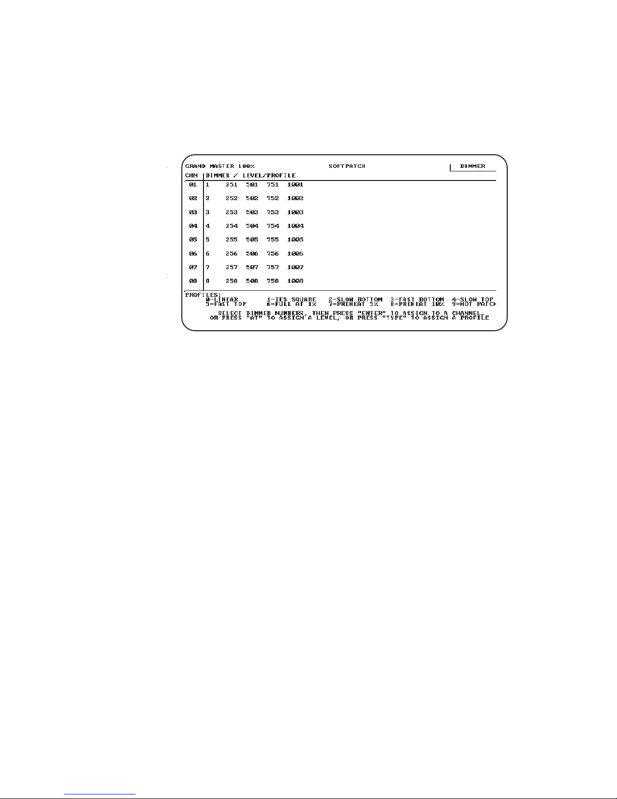
1. Press [Patch]
. Expression
displays the following screen.
2. Select dimmers to assign to a single channel
To select a single dimmer:
a) Enter the dimmer number.
b) Press [Enter].
.
To select a range of consecutive dimmers:
a) Enter beginning dimmer number.
b) Press [Thru].
c) Enter the ending dimmer number.
d) Press [Enter].
To select a discontinuous set of dimmers:
a) Enter dimmer number.
b) Press [And].
c) Enter additional dimmer numbers, pressing [And] between each.
d) Press [Enter] after you have selected all desired channels.
Page 43

Chapter 3 Entering softpatch and system settings 3 - 7
Shortcut: Combine [And] and [Thru] commands to select any combination of dimmers. For example, press [1] [Thru] [5] [And] [1][0]
[Thru] [2][0] to select one through five and 10 through 20.
3. Enter the channel number to which you want to assign selected
dimmers; then press [Enter].
4. To patch remaining dimmers, repeat steps two and three.
5. See instructions in this chapter titled
instructions on inhibiting individual dimmers.
Proportional patching
for
Page 44

3 - 8 Expression 2.0
Additional patching features
The following patching features are described below:
• Proportional patching
• Dimmer profiles
• Capturing channels in softpatch
• Unpatching individual dimmers
• Softpatching to Strand CD80 dimmer rack
Proportional patching
Expression
the softpatch screen. You may want to inhibit an individual dimmer to
balance the wash in a channel or to limit a particular lamp. Dimmers
default to a full level setting unless you inhibit them.
To inhibit individual dimmers levels, follow these steps:
1. If Softpatch screen is not displayed, press [Patch].
2. Press [Dim] to indicate that next number entered will be a dimmer.
3. Enter desired dimmer number, or select a group of dimmers by
using [And] and [Thru] in conjunction with dimmer numbers.
4. Press [At], and enter desired intensity level for dimmer
As long as dimmers are selected (highlighted on monochrome
monitor or displayed in yellow on a color monitor) you can adjust
their levels with [+] and [-].
Dimmer intensity levels set in softpatch function at full level on all other
screens. For example, if you enter a level of 60 for a dimmer on the
softpatch screen, when you set that channel to full in a cue or submaster, the dimmer will output at 60 percent.
lets you proportionally inhibit individual dimmer levels from
.
Page 45

Chapter 3 Entering softpatch and system settings 3 - 9
Dimmer profiles
Dimmer profiles allow you to select a specific output curve for a dimmer
over the range of a fade. This can compensate for nonlinear light outputs
from certain types of fixtures or incorporate a preferred response in a
fade. If you do not select a dimmer profile, the console defaults to a
linear output
To select a dimmer profile for a specific dimmer, follow these steps:
1. Press [Patch].
2. Press [Dim], and enter dimmer number or a range of dimmer
numbers using [And] and [Thru].
3. Press [Type].
4. Enter profile number. Profile numbers are listed on menu at the
bottom of the softpatch screen. Each is also described below. For
illustrations of dimmer profiles, see page 8 - 24.
0 - Linear
1 - IES square
2 - Slow bottom
3 - Fast bottom
4 - Slow top
5 - Fast top
6 - Full at 1%*
7 - Preheat 5%
8 - Preheat 10%
9 - Hot patch
.
†¶
†¶
‡¶
* Dimmer intensity jumps from 0% to 100% at 1%
output.
† Dimmer at 5% or 10% whenever console power is on.
Dimmer intensity increases when output exceeds 5% or
10%.
‡ Dimmer at full whenever console power is on.
¶ Affected by [Black Out] but not by Grand Master.
Page 46

3 - 10 Expression 2.0
Resetting factory dimmer profiles
and all dimmers to default setting
The Default Dimmer Profiles option on the System Settings Menu
allows you to reset all dimmers to the default (linear) profile and the
dimmer profiles to the original factory settings.
1. Press [Set Up].
2. Select 6, System Settings, and press [Enter].
3. Select 9, Default dimmer profiles, and press [Enter].
Capturing channels in softpatch
Expression
Stage mode so you can bring channels up on stage to view the proportional settings of dimmers assigned to a channel while you set them. To
select channels from the softpatch screen, follow these steps:
1. Press [Patch].
2. Press [Chan].
3. Enter channel number, or select a range of channels.
4. Press [Full] to set channel level at 100 percent, or press [At] and
enter a level setting.
5. Press [Rel] to release channel(s).
lets you select and capture channels without returning to
Page 47

Chapter 3 Entering softpatch and system settings 3 - 11
Unpatching individual dimmers
[Dim] lets you select a single dimmer and bring it up independent of
other dimmers softpatched to the same channel. This is called
unpatching a dimmer. If a channel has more than one dimmer
softpatched to it, you may want to unpatch a single dimmer to check
individual fixtures, to turn on a work light, or to focus a single dimmer
from the channel. You must be in Stage mode to unpatch a dimmer.
To unpatch a dimmer, follow these steps:
1. Determine which dimmer you want to unpatch. You may want to
display the softpatch screen to display the current dimmer to
channel patching. To display the softpatch screen, press [Patch]
.
2. Press [Stage]
3. Press [Dim]
4. Enter the dimmer number you want to unpatch. Unpatching does
not affect the level that other dimmers in the channel are set at. If
you want all other dimmers in the channel off, set the channel at
zero.
5. To set the unpatched dimmer at full intensity, press [Enter]. Or, to
set the unpatched dimmer at less than full, press [At], and enter a
two-digit level; then press [Enter].
6. Press [Dim] [Clear] to restore dimmer to patch. You can perform
most other console tasks with dimmer unpatched, then restore the
patch at any time. Entering the softpatch screen also restores patch.
.
.
Note: When you unpatch a dimmer and set it to full intensity, the output
is 100 percent of the potential output, not 100 percent of the level at
which it is softpatched.
Hint: To perform a dimmer check from Stage, press [Dim] [1] [Enter].
Then use [+] and [-] to step through remaining dimmers for dimmer
check.
Page 48

3 - 12 Expression 2.0
Softpatching to a Strand CD80 dimmer rack
Strand CD80 dimmer racks have 48 dimmer slots. Each dimmer slot
holds either two 2.4 kw dimmers or one 6 kw or 12 kw dimmer. The
console requires that you include all 96 possible dimmer numbers per
rack in the softpatch
Refer to the charts below to determine dimmer numbers for each slot
on each rack. When patching 6 kw or 12 kw dimmers, enter the slot’s
odd dimmer number under the desired channel number. Enter the slot’s
even dimmer number under channel 0
For example, to patch a 6 kw dimmer into the last dimmer slot on the
first rack, enter dimmer 95 in the desired channel number and dimmer
96 in channel 0.
.
.
1234567891011
12
1314151617181920212223
24
2526272829303132333435
36
3738394041424344454647
48
4950515253545556575859
60
6162636465666768697071
72
7374757677787980818283
84
8586878889909192939495
96
979899
100
109
111
110
112
121
123
122
124
133
135
134
136
145
147
146
148
157
159
158
160
169
171
170
172
181
183
182
184
101
102
113
114
125
126
137
138
149
150
161
162
173
174
185
186
103
104
115
116
127
128
139
140
151
152
163
164
175
176
187
188
105
106
117
118
129
130
141
142
153
154
165
166
177
178
189
190
107
108
119
120
131
132
143
144
155
156
167
168
179
180
191
192
Page 49

Chapter 3 Entering softpatch and system settings 3 - 13
Entering system settings
These system settings are discussed on the following pages:
• Default full level
• Default up and down fade times
• Default fader clear time
• Enable/disable bumpswitches
To display the System Settings Menu, follow these steps:
1. Press [Set Up].
2. Select 6, System Settings, and press [Enter]. The system setting
menu is illustrated below.
Page 50

3 - 14 Expression 2.0
Setting default full level
The default full setting is the level
channels when you press [Full]. [Full] is set originally at 100 percent, and
is reset to 100 percent after a diagnostic system clear.
When you set the default full level below 100 percent, you can still set
channels above the [Full] level setting by using [At], [+], [-], or the fader
wheel. To set [Full] at a level other than 100 percent, follow these steps:
1. Press [Set Up]
2. Select 6, System Settings, and press [Enter].
3. Select 1, Default Full Level, and press [Enter].
4. Either enter a two-digit intensity level, or press [Full] to set level at
100 percent.
.
Expression
enters for selected
Note: When you set dimmer levels on the softpatch screen, [Full] enters
100 percent regardless of the default full level setting.
Setting default up and down fade times
Expression
you specifically change them. A diagnostic system clear resets the
defaults to five seconds. To customize default fade times, follow these
steps:
automatically enters default up and down fade times unless
1. Press [Set Up].
2. Select 6, System Settings, and press [Enter].
3. Select 2, Default Up/Down Times, and press [Enter].
4. Enter upfade time in minutes and seconds or as a fraction of a
second in decimal format, then press [enter]. Fade times can be
from .1 second to 99:59 minutes
5. Enter downfade time in minutes and seconds or as a fraction of a
second in decimal format, then press [Enter]. Fade times can be any
length of time from .1 second to 99:59 minutes
.
.
Page 51

Chapter 3 Entering softpatch and system settings 3 - 15
Setting default fader clear times
The default fader clear time is the length of time required for a fader pair
[Clear] to fade out channels from the faders. A diagnostic system clear
resets [Clear] fade time to zero; channels black out immediately when
clear time is zero.
To change the fader clear time, follow these steps:
1. Press [Set Up].
2. Select 6, System Settings, and press [Enter].
3. Select 3, Default Fader Clear Time, and press [Enter].
4. Enter fader clear time in minutes and seconds or as a fraction of a
second in decimal format. Fade times can be any length of time
from .1 second to 99:59 minutes
5. Press [Enter].
.
Enable/disable bump switches
Bump switches are momentary switches that flash submasters to their
full recorded levels or initiate a timed submaster. You may disable bump
switches to eliminate the possibility of accidentally bringing up unwanted channels
When bump switches are disabled, submaster slide pots function
normally. To enable or disable bump switches, follow these steps:
1. Press [Set Up].
2. Select 6, System Settings, and press [Enter].
3. Select 14, Enable/disable bump switches, and press [Enter].
4. Select 0 to enable or 1 to disable bump switches.
5. Press [Enter].
.
Page 52

3 - 16 Expression 2.0
Enable/disable Flexichannel
Flexichannel is an optional display mode that displays only selected
channels and channels that are recorded in a cue, submaster, group, or
effect.
To enable or disable Flexichannel, follow these steps:
1. Press [Set Up].
2. Select 6, System Settings, and press [Enter].
3. Select 18, Enable/disable Flexichannel, and press [Enter].
4. Select 0 to enable or 1 to disable bump switches.
5. Press [Enter].
Page 53

Chapter 4 Learning the basics 4 - 1
chapter 4
learning the basics
This chapter includes lessons on working with
features: cues and submasters. When you complete the lessons, you
will have a short sample show to run. Each lesson is described briefly
below.
• Lesson 1 describes display and channel modes and record functions.
• Lesson 2 includes instructions for creating several cues using
several different methods.
• Lesson 3 includes instructions for playing back cues and
submasters.
• Lesson 4 includes instructions for creating submasters using several
different methods.
• Lesson 5 includes instructions for saving your work on disk.
If these lessons seem too elementary for you, but you want some
guidance on advanced features, read
techniques.
keystrokes and menu options, see
For an alphabetical listing and explanation of all features,
Chapter 5, Learning advanced
Chapter 8, Reference.
Expression’s
basic
Page 54

4 - 2 Expression 2.0
Lesson 1
Display, channel and
record modes
This lesson describes display and channel modes and record functions
available in
for cues, submasters, groups and fader pairs. Channel modes indicate
how channels respond when they are in different situations.
Expression's
functions
Display modes
You can work in any of four different modes to create and modify cues,
groups and submasters: Stage, Blind, Fader, or Track Sheet. The first
three modes have very similar screens; the Stage screen is illustrated
and described on the next page. The Track Sheet screen is illustrated
and described on page 5 - 17.
Expression.
record functions create cues differently. See
on page 4 - 8 for more information.
Display modes show channel and level settings
Record
Stage
Stage mode controls live channels. This mode allows you to adjust
lighting levels and save a look as a cue, group or submaster when you
are satisfied with the look on stage.
Blind
Blind mode allows you to work on cues, groups or submasters without
affecting the stage lights. Blind mode is useful when you know ahead of
time what channels and levels you want for most of your cues and
submasters. Blind also lets you jump ahead of the stage action and
make changes to recorded cues, groups or submasters without affecting
live stage lighting.
Fader
Fader mode lets you make live adjustments to channels that are in one
fader pair while another cue is currently running in the other. For example, if you have a cyclorama cue in one fader and a stage cue in the
other, Fader mode lets you modify the stage cue live and record
changes without capturing the cyclorama cue. Fader mode is not included in this tutorial, but it is described in
Chapter 8, Reference
.
Page 55

Chapter 4 Learning the basics 4 - 3
Track Sheet
Track Sheet displays a specific channel’s level settings in all recorded
cues. This display is useful when you need to add or modify a single
channel in several cues. Track is a blind mode; it does not give you live
control of channels. Track Sheet mode is included in
ing advanced techniques.
You can modify existing cues, but you cannot
Chapter 5, Learn-
create cues in Track Sheet.
Flexichannel
Flexichannel is a feature of
Expression’s
expanded memory option. It is
available only when expanded memory is installed.
When the Flexichannel mode is enabled,
Expression’s
monitor displays
only selected channels, and channels that are part of a recorded cue,
submaster, group, or effect; other channels do not appear on the
display screen. This simplifies console operation by eliminating unused
channels from the display screen. Once you have selected a
channel,the only way to remove it from the display is to repeat the
procedure for enabling Flexichannel. See
Chapter 8, Reference,
page
8 - 35 for information on enabling and using Flexichannel.
Page 56

4 - 4 Expression 2.0
Stage, Blind and Fader screens
Stage, Blind and Fader screens look very similar. The Stage mode screen
is illustrated below to familiarize you with the screen format
.
❶
Grand master setting
The grand master setting displays the master intensity level. With it you
can proportionally inhibit the level of all channels. The grand master
overrides all other settings.
❷
Mode label
This field displays the current mode, either Stage, Blind or Fader.
❸
Keypad prompt window
This window indicates how the console will interpret the next number
you enter from the keypad. For example, if you press [Chan], the keypad
prompt window displays the message Channel, indicating that the
console will read the next number you enter as a channel number.
❹
Channel display
The channel display lists available channels and their current levels. If
you have a color monitor,
Expression
color codes level displays to
Page 57

Chapter 4 Learning the basics 4 - 5
provide additional information about channels. For example, in Blind
mode tracked channels are green. See the section
page 4 - 6 for further description.
Note: In Flexichannel display mode, only selected channels and channels
that are part of a recorded cue, submaster, group, or effect are displayed; other channels do not appear on the display screen. Channels
are displayed in vertical columns rather than in horizontal rows. The
Flexichannel display is a feature of Expression’s expanded memory
option. See Chapter 8, Reference, Flexichannel for more information.
❺
Cue/submaster description line
The cue/submaster description line displays information about the
currently selected cue, group or submaster. The summary includes cue,
group or submaster number, up and down fade times, wait and delay
times, fade or submaster type, and link information, if applicable.
❻
Fader windows
Fader windows display fade time information for cues loaded in fader
pairs. The window displays the cue number, a running clock of the fade,
and the percentage of the fade time that has run
❼
Cue sheet
The cue sheet lists up to nine stored cues. Each cue listing includes
fade, wait and delay times, and cue name and link information.
Channel modes
.
on
❽
Operator prompt line
The operator prompt line displays messages to guide you through
Expression
displays the message, Select channel numbers. If you are having
problems, look here for information or help.
➒
Page display
The page display indicates which submaster page is currently loaded. If
any submasters from the previously loaded page are still active, the
message Page 2 loading is displayed. The message changes to Page 2
loaded when all submasters are loaded from the new page.
❿
Submaster window
The submaster window displays the current level settings for submasters. On a color monitor, pile-on submasters are displayed in green, and
inhibitive submasters are displayed in red
operations. For example, when you press [Chan], this line
.
Page 58

4 - 6 Expression 2.0
Channel modes
Channels may be in any of the following modes. Each mode responds
differently to your commands.
Captured channels
Captured channels are channels that you have selected and are live on
stage. They remain live until you press [Rel] to release them. Captured
channels override all other channel settings. For example, if a channel is in a fader at 100 percent and you capture it and set it to 50 percent,
Expression
channel.
You can capture channels while in either Stage or Fader mode, but not
Blind or Track Sheet modes since they are not live
captured channels in red and yellow on a color monitor. Red channels
are captured; yellow channels are captured
reads the 50 percent setting from the captured
. Expression
and
selected (see below).
displays
Selected channels
Selected channels are channels that you have immediate keyboard
control over. You can modify selected channels with [Full], [At], [+], [-], or
the fader wheel. Selected channels are highlighted on a monochrome
monitor and are displayed in yellow on a color monitor. You can select
channels in all display modes
Selected, captured
keyboard control. Channels can be
modes. You can select channels in Blind, but they won’t be captured
since Blind mode is not live.
.
channels are live channels that are under immediate
selected and captured
only in live
Page 59

Chapter 4 Learning the basics 4 - 7
Recorded channels
Recorded channels are channel levels that have been recorded in a cue,
group or submaster. In live modes (Stage and Fader), recorded levels
appear on the screen only when they are in a fader pair or in an active
submaster. On a color monitor in Stage mode, recorded levels are
displayed in blue. Recorded channels may be either moving or tracked in
Blind mode (see below).
Moving channels
Moving channels are channel levels that change from one cue to the
next. In Blind mode on a color monitor, moving channels are displayed in
blue. On a monochrome monitor, they are not displayed differently than
tracked channels.
Tracked channels
A tracked channel is a channel whose level is unchanged from the
preceding cue. On a color monitor, tracked channels are displayed in
green in Blind mode and on Track Sheet. Tracked channels are not
distinguished in Stage mode.
Page 60

4 - 8 Expression 2.0
Record functions
Expression
channels as they appear on the screen (what you see is what you get) in
the cue, group or submaster you specify. When you use Record to
record a cue, levels are recorded in only the cue you specify.
Track is a record function that works only for cues. It allows you to build
a new cue from the previous cue’s channel settings. Tracked channels
are channels whose levels do not change from one cue to the next. A
track
Track also allows you to add tracked channels through existing cues. For
example, if you have created all cues for a scene, and then decide to add
a new channel or group of channels to all cues, Track lets you do so with
one short record command. To do the same thing with Record would
require you to add the channels to each cue individually.
We use the standard Record function for all cues in this chapter. Instructions for using the Track function are included in
has two record functions Record and Track. Record saves all
often runs through several cues for the length of a scene or an act.
Chapter 5, Learning
advanced techniques.
Page 61

Chapter 4 Learning the basics 4 - 9
Lesson 2
Working with cues
Now that you have an orientation to the channel display screens, you’re
ready to create cues. If you are not sitting at the console but want to
refer to the keyboard, see
Appendix D
for an illustration.
When working with
recorded, and can replay in a timed fader pair. After you select channels
and set their intensity levels, you can store the look as a cue. You can
save up to 400 cues per show in
shows. If your performance runs over 400 cues, you can read a second
show from disk during a break, or between cues. See
information about recording shows on disk
This lesson includes instructions and examples for creating cues using
several different methods. When you have completed the lesson, you
will have five cues recorded. You will also know how to modify and
delete cues.
Naming cues with expanded memory
If you have installed the expanded memory option, you can use a
standard PC XT compatible, alphanumeric keyboard to assign alphanumeric names to cues, groups and submasters. The alphanumeric keyboard is an optional feature available with
memory option and is available only when expanded memory is installed. See page 7 - 3 for more information on using the alphanumeric
keyboard to name cues.
Expression
, a
cue
is a look you have created and
Expression.
Each disk can hold two
.
Expression’s
Lesson 5
expanded
for more
Page 62

4 - 10 Expression 2.0
Creating cues
Five cues are included in the following instructions. The first few are
simple; the rest use more complicated features. This lesson includes the
following sections:
• Cue 1, Creating a cue in Stage
• Cue 2, Creating a cue in Blind
• Cue 3, Modifying up and down fade times
• Cue 4, Linking cues
• Cue 5, Creating a cue using Solo
• Deleting cues
• Viewing cues
There are several methods you can use to create any one look with
Expression.
what information is already stored in the console.
If you have several cues already stored, you may want to use the look
from one cue and add to it to create another. In another circumstance,
you may want to enter all channel levels from scratch.
Deciding how to create a look depends on your situation and
If you are in the middle of a tech rehearsal you will probably want to use
Stage mode so you can see your adjustments live. If you have a good
idea of how you want cues to look, you may want to record the show in
Blind ahead of time.
The following instructions include general instructions with numbered
steps. Then there are specific keystroke sequences to create sample
cues.
There are several ways you can go about creating any one look. The
following instructions give examples of how you
cue. Experiment and add as much as you want to each
We assume that when you start this tutorial there are no cues stored in
the console. To erase the current show from the console, follow this key
sequence: [Set Up] [6] [Enter] [1][6] [Enter] [Enter].
could
generate each
.
Before you clear the
console, make sure that the show currently in the console memory is
saved on disk. When you clear the console, all show information is
erased.
Page 63

Chapter 4 Learning the basics 4 - 11
Cue 1: Creating a cue in Stage
Follow these steps to create a cue in Stage mode:
1. Press [Stage]
you are in Stage, you have live control of channels
automatically prompts you to enter a channel number.
2. Enter channel number(s) with numeric keypad.
3. Set intensity level by pressing [At] and entering a two-digit level,
moving the fader wheel, or pressing [+] and [-].
4. Press [Rec] to indicate that you want to record the cue.
5. Enter cue number with numeric keypad.
6. Press [Enter] to record cue
prompt.
7. Press [Rel] to release captured channels.
. Expression
displays the Stage mode screen. Once
. Expression
. Expression
returns to the Enter channel
Page 64

4 - 12 Expression 2.0
Cue 1 keystrokes:
Key Action
[Stage] Displays Stage mode.
[1] Selects channel 1.
[At] Indicates next number entered will be an intensity
level.
[7][5] Enters intensity level of 75 percent.
[Rec] Indicates that you want to record cue.
[1] Enters cue number.
[Enter] Records cue.
[Rel] Releases captured channels.
Page 65

Chapter 4 Learning the basics 4 - 13
Cue 2: Creating a cue in Blind
Follow these steps to create a cue in Blind mode, for a range of channels, using [Full]
used in cue 1 to indicate that they will downfade in cue 2.
. Expression
automatically enters 00 for channels you
1. Press [Blind]
have live control of channels in Blind
prompts you to enter cue number.
2. Enter cue number you want to record or display.
3. Press [Chan] to indicate that the next number entered will be a
channel number.
4. Enter channel number to mark start of a range of channels.
5. Press [Thru] to indicate you are entering a range of channels.
6. Enter channel number to mark end of range. Selected channels are
highlighted or displayed in yellow.
7. Press [Full] to set channels at full intensity level.
8. Press [Rec] to indicate that you want to record the cue
9. Press [Enter].
. Expression
displays Blind mode screen. You do not
. Expression
automatically
.
Note: When using [Full], you do not have to press [At] first.
Page 66

4 - 14 Expression 2.0
Cue 2 keystrokes:
Key Action
[Blind] Displays Blind mode screen.
[2] Selects cue 2.
[Chan] Indicates that the next number entered will be a
channel.
[1] Selects channel 1.
[Thru] Indicates you are going to enter a range.
Note: If you are entering a range of channels in Flexichannel mode, you
must press [Thru] [Thru] to indicate a range.
[1][5] Marks end of range. Channels 1 through 15 are
selected.
[Full] Enters full intensity level for selected channels.
[Rec] Indicates you want to record the cue.
[Enter] Records cue.
Page 67

Chapter 4 Learning the basics 4 - 15
Cue 3: Modifying up and down fade times
You may also want to modify cue up and down fade times. When you
create a cue,
times. However, you can easily change fade times using [Time]. See
page 3 - 15 for instructions on changing default fade times.
1. Press [Blind] if the Blind mode screen is not already displayed.
2. Add channels using numeric keypad and [And] or [Thru]; then enter
intensity levels.
3. Press [Rec] to indicate that you want to record the cue.
4. Enter cue number, and press [Enter].
Expression
assumes you want to use the default fade
5. Press [Time]
6. Enter upfade time between .1 and 99:59. You can enter time either
in minutes and seconds or a fraction of a second in decimal format
For example, all of the following are acceptable: .2, 00:12, 5.5, 5:30.
7. Press [Enter]
8. Enter downfade time, if different from upfade time. Enter a time
between .1 and 99:59. If you do not enter a time,
assumes you want the same downfade time as upfade time
9. Press [Enter]
10. Enter wait time. Wait time is the length of time after
upfade before the downfade starts. If you do not enter a wait time,
Expression
Note: If you modify fade times
.
.
.
assumes you want a wait time of zero.
after
you record the cue, you do not
Expression
beginning
.
the
have to rerecord the cue. Fade and wait times are automatically
added to cue information.
11. Press [Enter].
.
Page 68

4 - 16 Expression 2.0
Cue 3 keystrokes:
If you did not press [Rel] after you saved the last cue, channels 1
through 15 should still be selected on the Blind mode screen.
Key Action
[Chan] Indicates next number entered will be a channel.
[2][6] Marks beginning of range.
[Thru] Indicates that you are entering a range.
Note: If you are entering a range of channels in Flexichannel mode, you
must press [Thru] [Thru] to indicate a range.
[5][0] Marks end of range.
[Full] Enters full intensity for selected channels.
[Rec] Indicates you want to record cue.
[3] Enters cue number.
[Enter] Records cue.
[Time] Indicates that you want to change fade times.
[1][0] Enters ten second upfade time.
[Enter] Enters upfade time and prompts you for downfade time.
[Enter] Enters same fade time as for upfade.
[.5] Enters half-second wait time
[Enter] Records time settings.
.
Page 69

Chapter 4 Learning the basics 4 - 17
Cue 4: Linking cues
Expression
cally. You can link a string of cues, or you can create a loop to produce a
chase. You can also link cues to macros. For more information on linking
cues to macros, see page 8 - 46 in
1. Create and record a cue using techniques described for cues 1
through 3.
2. Press [Link].
3. Enter cue number to which you want to link current cue. You can
enter either a cue number that exists already or one you are going to
create. Press [Enter].
On the cue description line, the number of the linked cue and LK
appears. This information is also added to the cue sheet.
4. Enter delay time in minutes and seconds or as a fraction of a second
in decimal form. Delay times may be between .1 second and 99:59.
The delay time is the length of time between the start of the first
cue and the start of the cue it is linked to. For example, if the delay
time for the link is 10 seconds, the second cue upfade starts 10
seconds after the first cue’s upfade begins.
lets you link cues to create a sequence that runs automati-
Chapter 8, Reference
.
Expression
time of the first cue. That way, the cues run back to back. The total
running time of a cue is the longer of either the upfade time or sum
of the wait and downfade times
To change the delay time for a cue that is already linked, press [Link]
twice, enter delay time, and press [Enter].
enters a default delay time that equals the total running
.
Note: If you are entering link information for existing cues, you do
not have to rerecord the cue.
Page 70

4 - 18 Expression 2.0
Cue 4 keystrokes:
Key Action
[Blind] Displays Blind mode screen.
[Chan] Indicates that you are going to enter channel numbers.
[5][1] Selects channel 51.
[Thru] Indicates that you want to enter a range of channels.
Note: If you are entering a range of channels in Flexichannel mode, you
must press [Thru] [Thru] to indicate a range.
[7][5] Marks end of range of channels at 75.
[Full] Sets captured channels at full intensity.
[Rec] Indicates you want to record the cue.
[4] Enters cue number.
[Enter] Records cue.
[Link] Indicates that you are going to link another cue to cue 4.
[5] Selects cue 5 to link cue 4. Note that in this example we
have not created the link-to cue yet.
[Enter] Enters cue link information.
[1][0] Sets delay time to 10 seconds.
[Enter] Enters delay time.
Page 71

Chapter 4 Learning the basics 4 - 19
Cue 5: Creating a cue using Solo
Often you will create cues by adding to, subtracting from and modifying
previously recorded cues. [Solo] lets you select a subset of displayed
channels and delete all others
1. Press [Chan] to indicate that the next number entered will be a
channel number.
2. Enter channel number to mark the beginning of the subset to select.
3. Press [And] or [Thru] to indicate you are selecting a range of channels.
4. Enter another channel number with numeric keypad to mark the end
of the range.
.
5. Press [Solo]
6. Move the fader wheel, press [At], [+] and [-], or use [At] and numeric
keypad to set desired level.
7. Press [Rec] to indicate that you want to record the cue.
8. Enter cue number with numeric keypad.
9. Press [Enter] to record cue.
. Expression
deletes all unselected channels.
Page 72

4 - 20 Expression 2.0
Cue 5 keystrokes:
Assuming you are still in Blind and have cue 4 displayed, follow these
steps to create a cue using [Solo]:
Key Action
[Chan] Indicates that the next number entered will be a channel
number.
[6][0] Marks the beginning of the subset.
Note: If you are entering a range of channels in Flexichannel mode, you
must press [Thru] [Thru] to indicate a range.
[Thru] Indicates you are selecting a range of consecutive
channels.
[6][5] Marks the end of the range.
[Solo] Deletes all unselected channels (all channels except 60
through 65).
Fader wheel Sets desired level.
or [At], [+] and
[-], [At] and
numeric keypad
[Rec] Indicates that you want to record the cue
[5] Enters cue number.
[Enter] Records cue.
.
Page 73

Chapter 4 Learning the basics 4 - 21
Inserting cues
You may want to insert a cue between recorded cues. For example, you
may want to modify cue 1 slightly and insert it between cues 1 and 2
You can number cues with a one-digit decimal. Therefore, you can insert
up to nine cues between one and two (1.1, 1.2, etc.). To modify and
insert a cue, follow these steps:
.
1. Press [Blind]
number.
2. Enter cue number you want to modify.
3. Make modifications.
4. Press [Rec].
5. Enter cue number with a decimal to insert it between cues. If you do
not enter a new cue number, you will overwrite the existing cue.
6. Press [Enter].
. Expression
Insert cue keystrokes:
Key Action
[Blind] Displays Blind mode screen.
[1] Displays cue 1.
[Chan] [1][0] Modifies cue.
[Thru] [1][5],
fader wheel
automatically prompts you for a cue
[Rec] Indicates you want to record cue.
[1] [.] [1] Enters cue number 1.1.
[Enter] Records and inserts cue 1.1 between cues 1 and 2.
Page 74

4 - 22 Expression 2.0
Deleting cues
Follow these steps to delete a cue from a show.
1. Press [Blind]. You cannot delete cues from live modes.
2. Enter cue number you want to delete.
3. Press [Clear].
4. To delete just the current cue, press [Rec].
To delete the current cue and any channels that track from that cue,
press [Track]
5. Press [Enter].
.
For more information on tracking, see
techniques
.
Deleting cue keystrokes:
Key Action
[Blind] Displays Blind mode.
[Cue] Indicates next number entered will be a cue.
[1] Displays cue 1 on Blind mode screen.
[Clear] Indicates you want to delete cue.
[Rec] Indicates that you want to delete just this cue, not the
tracks.
[Enter] Deletes cue 1.
Chapter 5, Learning advanced
Page 75

Chapter 4 Learning the basics 4 - 23
Viewing cues
Once you have created a few cues, you may want to look at them. You
can view stored cues in two ways, live in Stage mode, or just on the
screen in Blind mode.
To view cues live, you must select the cue and play it back in a fader,
see
Lesson 3: Playing back cues
To view a cue just on the screen, select Blind mode and enter the cue
number you want. To view a different cue, press [Cue] and the new cue
number that you want to see
In Blind mode you can also use [+] and [-] to move through recorded
cues, and cue parts, one at a time. Press [Cue]; thereafter [+] displays
the next cue or part, and [-] displays the previous cue or part.
for instructions.
.
Page 76

4 - 24 Expression 2.0
Copying cues
Once you have created a cue, you may copy it and give it a new number.
This can be helpful if you want to create a cue based on one you have
already recorded. You can copy cues in Stage or Blind modes.
Follow these steps to copy a cue:
1. Press [Blind] or [Stage]. You can copy a cue in either mode.
2. If you are working in Blind mode, press [Cue], then enter the number of the cue you want to copy. Or, if you are working in Stage
mode, press [Cue], enter the number of the cue you want to copy,
then press [Go].
3. In either Stage or Blind, once the cue is displayed, press [Rec] [Cue],
the number of the new cue, and [Enter]. The new cue will be
recorded; the original cue will not be affected.
Copying cue keystrokes:
Key Action
[Blind] or [Stage] Selects operating mode.
[Cue] [1] or Displays selected cue.
[Cue] [1][Go]
[Rec] [Cue] [2] Copies Cue 1 and Cue 2.
Page 77

Chapter 4 Learning the basics 4 - 25
Lesson 3
Playing back cues
Now that you have some cues, you’re probably anxious to play them
back
. Expression
corded cues. The left fader in each pair (faders A and C) controls
upfades. The right fader in each pair (B and D) controls downfades.
You can playback cues one at a time through a single fader pair, or you
can playback a different cue in each fader pair at the same time.
You can also play a cue in one pair, leave it there, and then play another
cue in the second fader pair. This is one way to put two looks on stage
at the same time.
For example, you may want to play a 10 minute sunset cyc cue in one
fader pair while you play several cues during the same period downstage
in the other fader pair.
This lesson includes the following sections:
has two sets of timed fader pairs that playback re-
• Selecting cues
• Timed fader pair and LED displays
• Playing back cues
• Go to a different cue
• Controlling fades manually
• Back key
Page 78

4 - 26 Expression 2.0
Selecting cues
There are three ways a cue can be selected to playback on stage:
1) when a cue is playing,
2) you select a cue manually; or 3)
linked cues. You must be in Stage mode to select cues to playback.
Expression
automatically selects the next cue;
Expression
automatically selects
When one cue is playing,
consecutive cue to play next. To play the next cue, press either [Go] key
If you are working in Stage mode, you see the cue running on the
monitor. You can also run cues from Blind by pressing [Go].
To select a cue out of sequence, press [Cue], and enter the cue number
Then press either [Go] to start playing the cue.
Linked cues begin playing automatically. When you play a string of linked
cues, or a chase loop, you only need to start the first cue.
Expression
Timed faders and LED displays
Each fader has a strip of LEDs next to it. When running a timed
crossfade cue, the lit LEDs indicate how much of the cue has run. This is
displayed as a percentage. For example, when the LED’s are at 5, 50
percent of the cue has run.
In default operation,
In level override faders control the percentage of completion of the fade,
and can be used to take manual control of fades. Alternatively, you may
choose to use the faders in proportional rate override. In this mode the
faders control the rate of the fade, with the A and C faders controlling
the upfade rate and the B and D faders controlling the downfade rate.
Expression’s
assumes that you want the next
.
.
faders function in level override mode.
For information on taking manual control of fades, see the section titled
Controlling fades manually
later in this lesson.
Page 79

Chapter 4 Learning the basics 4 - 27
Playing cues back
To playback the cues you created in Lesson 2, follow these steps:
1. Press [Stage] to display Stage mode.
2. Press [Cue] to indicate that you want to select a cue.
3. Enter the cue number you want to playback. To playback cues you
recorded from Lesson 2, press [1][.][1].
4. Press either [Go] key. Cue 1.1 begins
want to play cue 2 next.
5. Press [Go] to start cue 2.
If you press [Go] before a cue finishes playing, the previous cue stops,
and the new cue begins from the levels at which the previous cue was
interrupted.
. Expression
assumes that you
Page 80

4 - 28 Expression 2.0
Go to a different cue
To playback a cue other than the selected (highlighted) cue on the cue
sheet, follow these steps:
1. Press [Cue].
2. Enter the cue number you want to play next.
3. Press [Go].
Hint: If you want to force a cue to its recorded levels immediately,
without waiting for the recorded fade times, when fade starts, pull
faders down to meet lit LEDs, then push them to 10 (100 percent).
Page 81

Chapter 4 Learning the basics 4 - 29
Controlling fades manually
Expression
playbacks with the AB and CD fader pairs: level override and proportional
rate override.
In both fader modes, setting faders at 10 before pressing [Go] plays
cues back as recorded; setting faders at 0 before you press [Go] gives
you manual control of fade from the beginning of cue. In level override
mode, if you start a cue and want to take manual control, slide faders
down to meet the lit LEDs
proportional rate override mode, you must move the faders below 5 to
take manual control.
provides two fader modes to take manual control of cue
. Expression
gives you control of the fades. In
Hint: If you start a cue, and the performers skip ahead to the next cue,
you have two options for speeding up to the next cue. If you do not
need the current cue to reach its full intensity level settings, press [Go]
to interrupt the current cue and begin the next one. However, if you
need the current cue to reach its full level settings, push the slides down
to the lit LEDs and then back up to 10 immediately. Then press [Go] to
start the next cue.
Page 82

4 - 30 Expression 2.0
Level override
Level override is
you can use the faders to take manual control of fade levels. When you
take manual control, the movement of the faders controls the completion of the fade.
When you move the faders to a point lower than 10 in level override
mode, the cue runs until it reaches the fader level setting. You can set
the level before you start the cue running, or move the faders once the
fade starts. The fade stops when it reaches the level at which the faders
are set, and you then have manual control of fade rates. For example, if
you set faders at 8, the cue will play back to 80 percent of its recorded
levels.
Expression’s
Proportional rate override
If you prefer, you can select proportional rate override from the System
Settings Menu. In proportional rate override, the position of the faders
determines the
the upfade rate; the right fader controls downfade rate.
The fader setting determines the percentage of the recorded rate at
which the cue plays back. To take manual control of the fade rate, move
the faders to a point below 5, then move the faders to the desired
position. The percentage is determined by the level at which the faders
are set. Setting a fader at 0 stops the fade; setting it at 5 sets the fade
rate at 100 percent of the recorded rate. If you set a fader at 10, the fade
is instantaneous. You can set the level before you start the cue running,
or move the faders once the fade starts.
rate
at which a fade progresses. The left fader controls
default operating mode. In level override,
Page 83

Chapter 4 Learning the basics 4 - 31
Selecting fader operating mode
Follow these steps to select the desired fader mode:
1. Press [Setup].
2. Select 6, System Settings Menu, and press [Enter].
3. Select 6, Level/Proportional Rate Override, and press [Enter].
4. Press [0] to select level override mode, or press [1] to select proportional rate override mode.
Manual control of linked cues
When you play back linked cues, the left fader in each fader pair controls
intensity levels; the right fader controls the playback rate. When you
begin a linked cue sequence with the right fader at 10,
it back at the recorded rate. The LED strip on the right fader indicates
that playback is at recorded rate by holding at 5. To take manual control
of the playback rate, move the fader down to 5, then move it up or down
to adjust rate. Moving the fader control to 10 makes playback instantaneous; moving it to 0 stops playback.
Expression
plays
If right fader is set at anything other than 10 when you start the
autoload, the linked cues or effects playback at the rate set on the fader.
Page 84

4 - 32 Expression 2.0
Modifying cues on stage
To modify and record a cue on stage, follow these steps:
1. Press [Stage].
2. Press [Cue], and enter cue number.
3. Press [Go] to playback cue.
4. Push faders down and back up to avoid fade times.
5. Modify cue.
6. Press [Rec].
7. To rerecord as same cue, press [Enter].
To record as a new cue, enter new cue number, and press [Enter].
8. Release captured channels.
Note: If you rerecord as same cue, modifications are reflected in fader.
If you record the cue with a new number, modifications are not reflected
in the fader; you may want to run cue through fader before you release
channels if you don’t want to lose the look from stage.
Page 85

Chapter 4 Learning the basics 4 - 33
Update cue
The preceding steps allow you to record the entire on stage look into the
modified cue. To add only
cue feature.
1. Press [Stage].
2. Press [Cue], and enter cue number.
3. Press [Go] to playback cue.
4. Push faders down and back up to avoid fade times.
5. Add channels and set levels, or modify levels of existing channels.
6. Press [Update] [Cue] [Enter] to update the existing cue, or [Update]
[Cue] a new cue number, and [Enter] to record the updated cue as a
new cue.
7. To rerecord as same cue, press [Enter].
selected
channels to the cue, use the Update
To record as a new cue, enter new cue number, and press [Enter].
8. Release captured channels.
Page 86

4 - 34 Expression 2.0
Back key
The back key replays the most recently played cue, regardless of the
order in which the cues were recorded in the cue sheet. It then plays
subsequent cues in reverse numerical order. For example, if you play
cues one, two, three, twenty-two, and sixteen, then press [Back], cue
sixteen will fade into cue twenty-two. If you press [Back] again, cue
twenty-one will play, not cue three.
Cues are played back using the fade and wait times recorded with the
cue.
Back allows you to play back cues loaded in either fader pair. If you are
using only one fader pair, you need only press [Back] to replay the
previous cue. If you have cues loaded into both fader pairs, you must
press [Back] then the [Go] button below the desired fader pair. If you
play cues one, two and three in the AB fader pair and cues six, seven
and eight in the CD fader pair, pressing [Back] then the AB [Go] plays
back cue two; pressing [Back] then the CD [Go] plays back cue seven.
Note: Each time you press [Back], Expression resets the cue sheet. The
cue replayed with Back becomes the first cue in the cue sheet. If you
then press [Go] without first pressing [Back], the next numerical cue
plays.
Page 87

Chapter 4 Learning the basics 4 - 35
Clearing fader pairs
Each timed fader pair is equipped with a blue [Clear] key. To clear a cue
from the fader pair, press the appropriate [Clear] key. Faders will clear
immediately unless you have reset the default fader clear time. For
instructions on changing fader clear time, see page 3 - 15.
Page 88

4 - 36 Expression 2.0
Lesson 4
Working with submasters
Expression
submaster is a set of channels recorded at levels to create a look. The
submaster pot gives you manual control for the recorded look. You
cannot play submasters back through autofader pairs. Submasters allow
you to save looks that you use often. You can use submasters as
building blocks when you create cues or other submasters. For example,
you might create a different submaster for each cyclorama wash;
another submaster might include practicals. Or, you might choose to
create a series of submasters for each area of your set
Each submaster consists of a slide control and a bump switch. The slide
control allows you to bring the submaster look up manually
The bump switch allows you to flash the submaster to its full recorded
level or to begin its programmed fade time, if any.
When a slide pot is set at 0, the submaster is at zero percent of its
recorded level. To increase submaster level, push pot up. When pot is
set at 10, submaster is at 100 percent of recorded level
Expression
outputs (timed playback faders and other submasters) include the same
channel, the highest output level overrides all others. However, captured
channels and inhibitive submasters override pile-on submaster levels.
Any specific channel may be included in as many pile-on submasters as
you choose.
is equipped with 24 submaster potentiometers, or
.
.
.
submasters are pile-on submasters. That is, if several
pots.
A
Half of
inhibitive
the channels recorded in it
inhibitive submasters.
Expression’s
submasters. Inhibitive submasters limit the intensity level for
submasters can be recorded as either pile-on or
.
See page 4 - 43 for more information on
Page 89

Chapter 4 Learning the basics 4 - 37
Naming submasters with expanded memory
If you have installed the expanded memory option, you can use a
standard PC XT compatible, alphanumeric keyboard to assign names to
submasters. See page 7 - 3 for more information on using the alphanumeric keyboard to name submasters.
This lesson includes the following sections:
• Submaster pages
• Creating pile-on submasters
• Recording submasters on a different page
• Adding fade times to submasters
• Controlling submaster fades manually
• Modifying pile-on submasters
• Creating inhibitive submasters
• Recording inhibitive submasters on a different page
• Modifying inhibitive submasters
• Using Update to modify submasters
• Copying submasters
• Deleting submasters
• Submaster sheet
After creating cues in Lesson 2, you should be well acquainted with
several methods for creating looks on stage. In this lesson, we won’t
trouble you with reading instructions on selecting channels and setting
levels since you already know how to do that. Instead, we’ll concentrate
on how creating submasters is different from creating cues.
Page 90

4 - 38 Expression 2.0
Submaster pages
Expression
of recorded submasters, one in each pot. This doubles the number of
recorded submasters available.
Expression
the Page Display window to indicate which page is currently active. To
switch pages, press [Page]; enter the page number you want, and press
[Enter].
The message indicates the new page number and displays the message
Loading instead of Loaded
When you load a new page, any submasters set at a level above zero
remain on stage until you pull them down to zero. This prevents the
stage from going black when you switch pages. Submasters remaining
from the previous page are indicated by flashing bump switch LEDs
Submasters on the new page are not loaded into pots until you pull them
down to zero. The message Loading remains on the screen until all
submasters on the new page are loaded
has two
displays the message Page 1 Loaded (or Page 2 Loaded) in
pages
of submasters. Each page can hold a full set
.
.
.
Note: When you read a new show into the console from a disk, the
console loads the same page number that was loaded from the previous
show.
If any submasters are on stage when you read a new show into the
console, they will remain on stage until you pull pots down to zero.
Submaster LEDs flash to indicate that the associated submaster levels
are not from the currently loaded page.
Page 91

Chapter 4 Learning the basics 4 - 39
Creating pile-on submasters
Creating a submaster is as easy as creating a cue. You can create
submasters in Stage or Blind mode. To create a submaster, follow these
steps:
1. Select channel and level settings as you did for cues. See
Creating cues
from other submasters or cues by bringing up a recorded look, then
modifying as you desire.
2. Press [Rec], and press the bump switch where you want to record
the submaster.
Or, press [Rec] [Sub], then enter a submaster number, and press
[Enter].
3. Press [Rel] to release captured channels.
4. Push the submaster pot up. The channels you recorded come up at
the proportionate levels you recorded.
if you need a review. You can use channel settings
Lesson 2,
Page 92

4 - 40 Expression 2.0
Recording submaster on a different page
You may record a submaster to a page other than the one currently
loaded or loading. For example, if you have page one loaded, you can
create a look on stage and record it to page two if you wish. To do so,
follow these steps:
1. Create a look on the screen.
2. Press [Rec].
3. Press [Page].
4. Enter the page number on which you want to record submaster.
5. Press the bump switch of the submaster in which you want to
record the look.
Page 93

Chapter 4 Learning the basics 4 - 41
Adding fade times to submasters
Bump switches let you add upfade, downfade and wait times to submasters. When you record fade times for a submaster, you can play the
recorded fade with the bump switch or retain manual control with the
sliding fader.
You can add fade times to a submaster from any mode. To add fade
times to an existing submaster, follow these steps:
1. Press [Sub] to indicate that you are selecting a submaster.
2. Enter the submaster number to which you want to add fade times.
3. Press [Time]
4. Enter upfade time in minutes and seconds or as a fraction of a
second as a decimal, and press [Enter]. Upfade time cannot exceed
two minutes.
5. Enter wait time, and press [Enter]. Wait time is the length of time
the submaster holds a look before starting to downfade
To enter an infinite wait time, press [-]. If you record a submaster
with an infinite wait time, the submaster will not fade out until you
press the bump switch again.
If you do not enter a wait time, upfade runs as long as you press the
bump switch; the downfade begins when you release it. Therefore,
when you haven’t recorded a wait time, and if you don’t hold the
bump switch for the duration of the fade time, channels do not
reach their full recorded levels
Also, if you press the bump switch and hold it beyond the length of
the upfade time, the downfade does not begin until you let the
switch up.
Note: The
upfade, versus a cue wait time that begins at the
.
.
wait
time for a submaster begins at the
.
end
of the
start
of the upfade.
6. Enter downfade time in minutes, seconds or as a fraction of a
second as a decimal. Downfade cannot exceed two minutes.
7. Press the bump switch to start submaster upfade. The submaster
runs as described above.
Page 94

4 - 42 Expression 2.0
Controlling submaster fades manually
When a timed submaster pot is set at zero and you press the bump
switch, recorded fade times playback as you recorded them. However,
you can take manual control over fades, much as you can for cue fades.
You can increase the upfade rate by pushing the pot ahead of the
programmed fade rate. You can force the downfade to start early by
pressing the bump switch, but you cannot change the fade time.
Once a timed submaster is running, pressing the bump switch changes
the direction of the fade. For example, if half of the upfade is complete,
pressing the bump switch starts the downfade from 50 percent. If a
downfade is running, pressing the bump switch begins an upfade again
from the current level.
Hint: You cannot cancel a timed submaster once it’s started. However,
you can force the channel levels to zero with the following key sequence. Press [Group] [Sub] and the number of the running submaster.
Then press [Inhib Sub] and any available inhibitive submaster bump
switch. This puts all channels included in the running submaster in an
inhibitive submaster. Pull inhibitive submaster level to zero.
Modifying pile-on submasters
To modify a recorded pile-on submaster, follow these steps:
1. Press [Blind] to display Blind mode.
2. Press [Sub] and the number of the submaster you want to modify.
3. To add or change channels:
Select channel numbers and set desired levels.
To change all channels proportionately:
Press [Group], [Sub] and enter the submaster number you are
modifying. This selects all channels at current levels. Move the fader
wheel to proportionately modify levels.
To delete channels:
Select channels and press [Clear] to set them to 00
4. Press [Rec] [Enter].
.
Page 95

Chapter 4 Learning the basics 4 - 43
Creating inhibitive submasters
Inhibitive submasters allow you to limit the intensity level for a group of
channels. When an inhibitive submaster pot is on 10 (100 percent), the
channels are not inhibited. As you pull the pot down, the channels’ levels
are limited to the percentage to which you set the submaster
For example, assume you select channels 1 through 15 for an inhibitive
submaster. As long as the submaster is set at 10 (100 percent), channels 1 through 15 are not affected. When you pull the submaster down
to 5 (50 percent), channels 1 through 15 are limited to 50 percent of any
other output settings.
Each channel can be included in only one inhibitive submaster. If you
assign a channel to an inhibitive submaster that is already included in
another,
submaster that you most recently recorded.
Expression
removes it from the first one, and adds it to the
.
Inhibitive submasters affect timed fader pairs and other submasters
Captured channels are not affected by inhibitive submasters, but cues
playing back through timed fader pairs are.
.
Remember, leave inhibitive submasters at 10 (100 percent) unless you
want to inhibit channels. Otherwise channels may be missing from your
cues. If you seem to be missing some channels, check your inhibitive
subs!
You can record submasters 13 through 24 either as pile-on or inhibitive.
A lit red LED in the bump switch indicates that an inhibitive submaster is
recorded
Follow these steps to create an inhibitive submaster:
1. Press either [Stage] or [Blind]
2. Press [Chan] to indicate that next number entered will be a channel.
3. Enter the channel numbers you want to include in the submaster
.
.
using the numeric keypad, [And] and [Thru]
.
Page 96

4 - 44 Expression 2.0
Expression
saves only selected channels when you record an
inhibitive submaster (on a color monitor, selected channels are
displayed in yellow). If unselected channels are also displayed, they
will not be included in the submaster
.
4. Press [Rec] [Sub] [-] to indicate that you want to save selected
channels in an inhibitive submaster
.
5. Press the bump switch of the submaster you want to record
Red LED in a bump switch indicates that you have recorded an
inhibitive submaster
.
.
Page 97

Chapter 4 Learning the basics 4 - 45
Recording inhibitive submasters on a different page
You may record an inhibitive submaster to a page other than the one
currently loaded or loading. For example, if you have page one loaded,
you can create an inhibitive submaster and record it to page two. To do
so, follow these steps:
1. Select the desired channels.
2. Press [Rec].
3. Press [Sub] [-].
4. Press [Page].
5. Enter the page number on which you want to record the inhibitive
submaster.
6. Press the bump switch of the submaster you want to record as an
inhibitive submaster.
Modifying inhibitive submasters
You can not use the [Update] key to modify inhibitive submasters. To
modify an inhibitive submaster, follow these steps:
1. Press [Blind].
2. Press [Sub], and enter the submaster number.
Note: If you press [Rec] [Enter], Expression deletes the submaster.
3. Select the channels you want to add or remove from the submaster.
4. Press [Rec] [Sub] [-] and the submaster bump switch to add the
selected channels. Or, press [Clear] [Rec] [Sub] [-] and the submaster bump switch to delete them.
Page 98

4 - 46 Expression 2.0
Using Update to modify submasters
In Stage mode, [Update] allows you to modify, or add channel levels to,
a recorded submaster without recording the entire stage look to the
submaster you are modifying
Follow these steps to update a submaster:
1. Press [Stage] to display Stage mode.
2. Select and set desired levels of the channels you want to
add to the submaster.
3. Press [Update] [ Sub], and enter the number or press the bump
button of the submaster you want to update.
.
Copying submasters
You may want to copy a submaster or use submasters as building blocks
for new submasters. To copy a look from one submaster to another in
Stage, follow these steps:
1. Press [Stage].
2. Set submaster pot(s) that you want to copy at desired level.
3. Make any additional adjustments you want, such as selecting
channels to add, playing back cues through fader pairs, bringing up
other submasters, or selecting groups.
4. Press [Rec].
5. Press [Page], and enter the page number onto which you want to
copy the submaster, if it is not the currently loaded page.
6. Enter new submaster number, and press [Enter]. Or, press the
submaster bump switch.
Page 99

Chapter 4 Learning the basics 4 - 47
Deleting submasters
You must be in Blind to delete individual submasters. To delete all
submasters and all other show information, you can use the Set Up
Menu option
To delete submasters, follow these steps:
Diagnostic system clear.
It is described on page 8 - 21.
1. Press [Blind] and then [Sub]
2. Enter submaster number you want to delete.
3. Press [Clear]
4. Press [Rec] to delete the submaster or [Clear] to cancel the action.
.
.
Page 100

4 - 48 Expression 2.0
Submaster sheet
Submaster sheet is a feature of
Expression’s
expanded memory option.
It is available only when expanded memory is installed.
Submaster sheet allows you to view submasters on the display screen.
All 24 submaster pots per page are represented on the submaster sheet.
Submasters with recorded levels are displayed in green; those with no
recorded levels are displayed in blue. Inhibitive submasters are displayed
in red. If a submaster is recorded with specified upfade and downfade
times, the times are displayed. Alphanumeric names are also displayed if
this option is installed.
The submaster sheet lists all 24 submasters. Page one and two are
displayed separately.
Follow these steps to display submaster sheet:
1. Press [Blind] [Sub] [Page] to display submaster sheet, page one.
2. Press [Page] to toggle between submaster page one and page two.
 Loading...