

Page 1
ETC Installation Guide
•
•
•
•
•
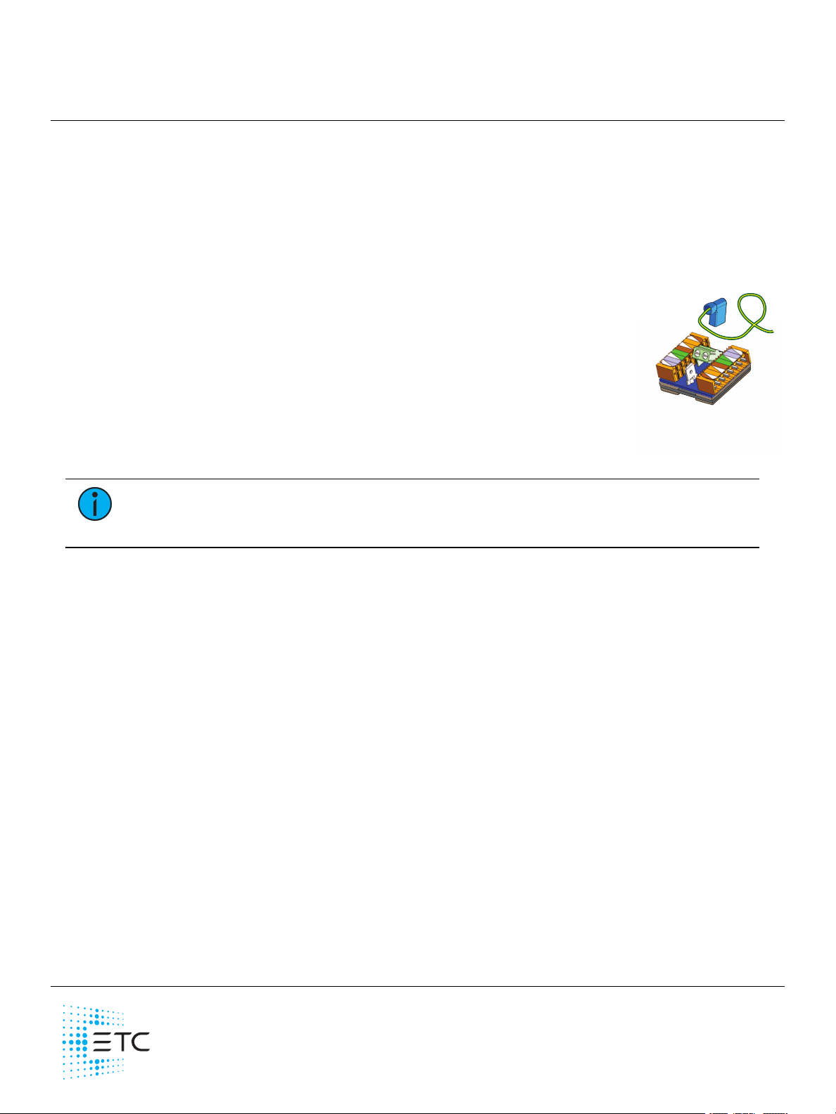
Echo EchoConnect Cat5 Termination Kit
Overview
The EchoConnect Cat5 station termination kit facilitates termination of Category 5 (or equivalent) c able
on the EchoConnec t c ommunication bus. ETC recommends using Belden 1583A (or approved equal)
wire. The total combined length of an EchoConnec t wire run using Cat5 may not exceed 305 m
(1,000ft). Contact ETC Professional Servic es for guidance when installing a topology -free system.
The included Cat5 term ination board includes a Cat5 input and optionally a Cat5 through c onnection, as
well as a two-position screw terminal for connection between the Cat5 term ination board and an Echo
control station.
This kit includes the following:
Cat5 stati o n termination board
On e ESD gro u nd wire pig tai l with a FASTON connector attached
2 each eigh t-p ositi on female IDC connectors (J3409-F)
3 each cable ties
Cat5 Cable Preparation for IDC Termi n ati on Setup Guide
Installation
1.
Refer to the provided
cable for termination to the Cat5 station termination board.
Cat5 Cable Preparation for IDC Termination Setup Guide
(410 0M2202)
to prepare the Cat5
Note:
The connector referenced in Step 4 of the Cat5 Cable Prepara tion for IDC
Te rmination Setup Guide is the eight-position connector (J3409-F) provided in this
termination k it.
2.
Connect the ESD ground wire pigtail.
a.
Strip 9-10 mm (3/8 in) of insulation from the end of the ground wire pigtail and the Echo
control station ground wire.
b.
Use one WAGO connector, provided in the Echo station installation kit, to connect the station
ESD ground pigtail and the Cat5 termination board ESD ground pigtail. Open two term inal
lev ers on the WAGO connector and insert each ground wire into a terminal.
c.
Close the levers onto the wires.
d.
Install the FASTON connec tor to the receptacle on the Cat5 termination board.
3.
Connect EchoConnect wiring.
a.
Strip 9-10 mm (3/8 in) of insulation from the end of the EchoConnect power pigtail (prov ided
with the station).
b.
Loosen the two-position screw terminals on the Cat5 termination board.
c.
Insert the white wire (typic al) into terminal 1 ( identified with a + symbol and an arrow on the
board) and the blac k wire into the rem aining terminal.
d.
Secure the screws firm ly onto each wire.
e.
Connect the other end of the EchoConnec t pigtail (two-position connec tor) to the two-pin
receptacle on the Echo station.
4.
Connect the Cat5 input c onnector (and optionally the output connec tor) to the Cat5 termination
board.
a.
Connect the IDC connector with prepared data input cable from the station bus to the
receptacle on the Cat5 termination board.
b.
Connect the IDC connector with prepared output cable to the remaining Cat5 receptacle on
the Cat5 term ination board.
5.
Remove the protective backing from the mounting tape and secure the termination board to the
inside of the station back box.
Corpora te Hea dquarters Middleton, WI, USA +1 608 83 1 41 16 London, UK +44 (0) 20 8 89 6 1000
Holzk irchen, DE +49 ( 80 2 4) 47 00-0 Rom e, IT +39 (06 ) 32 1 11 6 83 Hong Kong +85 2 27 99 1 220 P aris, FR +3 3 1 42 43 35 35
We b etc conne ct.c om Support support.etcc onnect.com Conta ct e tcc onnec t.com /contactET C
© 2 020 Electronic Theatre Controls, Inc . T rade mark and pa tent info:etcc onnect.com/ip
Product information and specifications subjec t to cha nge. ET Cintends this docume nt to be provided in its e ntirety.
71 86M21 5 0 Rev C Released 202 0- 01
 Loading...