

Page 1

This product is intended for professional use only.
Read this entire document before using this product.
Copyright © 2015 Electronic Theatre Controls, Inc.
All rights reserved. Product information and specifications subject to change.
Part Number: 7121M1200-1.0.0
Released: 2015-12
ColorSource ThruPower
User Manual
1.0
rev A
Page 2

ETC® is a registered trademark of Electronic Theatre Controls, Inc. in the United States and other
countries.
All other trademarks, both marked and not marked, are the property of their respective owners.
ETC intends this document, whether printed or electronic, to be provided in its entirety.
Page 3

Table of Contents i
Table of Contents
Introduction . . . . . . . . . . . . . . . . . . . . . . . . .1
Document conventions . . . . . . . . . . . . . . . . . . . . . . . . . . . . . . . . . . 1
Help from ETC Technical Services . . . . . . . . . . . . . . . . . . . . . . . . . . 2
Overview . . . . . . . . . . . . . . . . . . . . . . . . . . .3
12-circuit models . . . . . . . . . . . . . . . . . . . . . . . . . . . . . . . . . . . . 3
24-circuit models . . . . . . . . . . . . . . . . . . . . . . . . . . . . . . . . . . . . 4
Standard features . . . . . . . . . . . . . . . . . . . . . . . . . . . . . . . . . . . . . . 4
Product variants. . . . . . . . . . . . . . . . . . . . . . . . . . . . . . . . . . . . . . . . 5
Supply voltage and current . . . . . . . . . . . . . . . . . . . . . . . . . . . 5
Power supply and control . . . . . . . . . . . . . . . . . . . . . . . . . . . . 5
Option kits . . . . . . . . . . . . . . . . . . . . . . . . . . . . . . . . . . . . . . . . . . . . 6
Chapter 1 Menus and configuration . . . . . . . . . . . . . .7
User interface. . . . . . . . . . . . . . . . . . . . . . . . . . . . . . . . . . . . . . . . . . 7
LED indicators . . . . . . . . . . . . . . . . . . . . . . . . . . . . . . . . . . . . . . 7
Keypad. . . . . . . . . . . . . . . . . . . . . . . . . . . . . . . . . . . . . . . . . . . . 8
LCD. . . . . . . . . . . . . . . . . . . . . . . . . . . . . . . . . . . . . . . . . . . . . . . 8
Initial power up display . . . . . . . . . . . . . . . . . . . . . . . . . . . . . . 9
ThruPower configuration . . . . . . . . . . . . . . . . . . . . . . . . . . . . . 9
Menu structure . . . . . . . . . . . . . . . . . . . . .10
Home screen . . . . . . . . . . . . . . . . . . . . . . . . . . . . . . . . . . . . . . . . . 10
Settings menu . . . . . . . . . . . . . . . . . . . . . . . . . . . . . . . . . . . . . . . . 11
DMX. . . . . . . . . . . . . . . . . . . . . . . . . . . . . . . . . . . . . . . . . . . . . 11
Output Setup . . . . . . . . . . . . . . . . . . . . . . . . . . . . . . . . . . . . . 14
General Settings . . . . . . . . . . . . . . . . . . . . . . . . . . . . . . . . . . . 16
About. . . . . . . . . . . . . . . . . . . . . . . . . . . . . . . . . . . . . . . . . . . . 18
Test menu. . . . . . . . . . . . . . . . . . . . . . . . . . . . . . . . . . . . . . . . . . . . 18
Enter the Test menu . . . . . . . . . . . . . . . . . . . . . . . . . . . . . . . . 18
Set dimmer levels in the Test menu. . . . . . . . . . . . . . . . . . . . 18
Exit the test . . . . . . . . . . . . . . . . . . . . . . . . . . . . . . . . . . . . . . . 20
Appendix A Service and maintenance . . . . . . . . . . . . .21
Maintenance . . . . . . . . . . . . . . . . . . . . . . . . . . . . . . . . . . . . . . . . . 21
Vacuum the vents . . . . . . . . . . . . . . . . . . . . . . . . . . . . . . . . . . 21
Page 4

ii ColorSource ThruPower User Manual
Vacuum the interior . . . . . . . . . . . . . . . . . . . . . . . . . . . . . . . . 21
Replacement parts . . . . . . . . . . . . . . . . . . . . . . . . . . . . . . . . . 22
Troubleshooting . . . . . . . . . . . . . . . . . . . .23
Appendix B Menu flow chart . . . . . . . . . . . . . . . . . . . .25
Page 5
Introduction 1
Introduction
Welcome to the ColorSource ThruPower User Manual. ColorSource ThruPower is a passively
cooled wall mount cabinet designed for use in low noise environments. This product
continues ETC's tradition of providing the highest quality products for the entertainment and
architectural lighting market.
Document conventions
This document uses the following conventions to draw your attention to important
information.
ETC's user documents are designed for printed or electronic use. However, there are many
advantages to using the electronic (PDF) versions. In addition to the benefits of a PDF (such as
word search, bookmarks, and commenting tools) you can click on headings in the Table of
Contents and jump to the desired page. Throughout this document, any cross-references
(indicated in blue italics like this: Introduction on page 1) are links that may be clicked to jump
to the specific part of the manual.
All of ETC's documents are available for free download from our website:
www.etcconnect.com
.
Please email comments about this manual to: TechComm@etcconnect.com.
Note:
Notes are helpful hints and information that is supplemental to the main text.
CAUTION:
A Caution statement indicates situations where there may be undefined or
unwanted consequences of an action, potential for data loss or an equipment
problem.
WARNING:
A Warning statement indicates situations where damage may occur,
people may be harmed, or there are serious or dangerous
consequences of an action.
WARNING:
RISK OF ELECTRIC SHOCK! This warning statement indicates situations
where there is a risk of electric shock.
Page 6

2 ColorSource ThruPower User Manual
Help from ETC Technical Services
If you are having difficulties, your most convenient resources are the references given in this
document. To search more widely, try the ETC website at www.etcconnect.com
. If your
questions are not sufficiently addressed by these resources, contact ETC Technical Services
directly at one of the offices identified below. Emergency service is available from all ETC
offices outside of normal business hours.
When calling for help, please:
• Have a detailed description of the problem
• Be near the equipment, for troubleshooting
• Have the notification number if you have called in previously
Americas United Kingdom
Electronic Theatre Controls Inc. Electronic Theatre Controls Ltd.
Technical Services Department Technical Services Department
3031 Pleasant View Road 26-28 Victoria Industrial Estate
Middleton, WI 53562 Victoria Road,
800-775-4382 (USA, toll-free) London W3 6UU England
+1-608 831-4116 +44 (0)20 8896 1000
service@etcconnect.com service@etceurope.com
Asia Germany
Electronic Theatre Controls Asia, Ltd. Electronic Theatre Controls GmbH
Technical Services Department Technical Services Department
Room 1801, 18/F Ohmstrasse 3
Tower 1, Phase 1 Enterprise Square 83607 Holzkirchen, Germany
9 Sheung Yuet Road +49 (80 24) 47 00-0
Kowloon Bay, Kowloon, Hong Kong techserv-hoki@etcconnect.com
+852 2799 1220
service@etcasia.com
Page 7
Overview 3
Overview
The ColorSource ThruPower is designed to provide professional quality dimming, packaged
for venues that require affordable, professional quality wall mount dimming in low noise
environments. The cabinet may be installed with or without other system components
making it a cost-effective power solution.
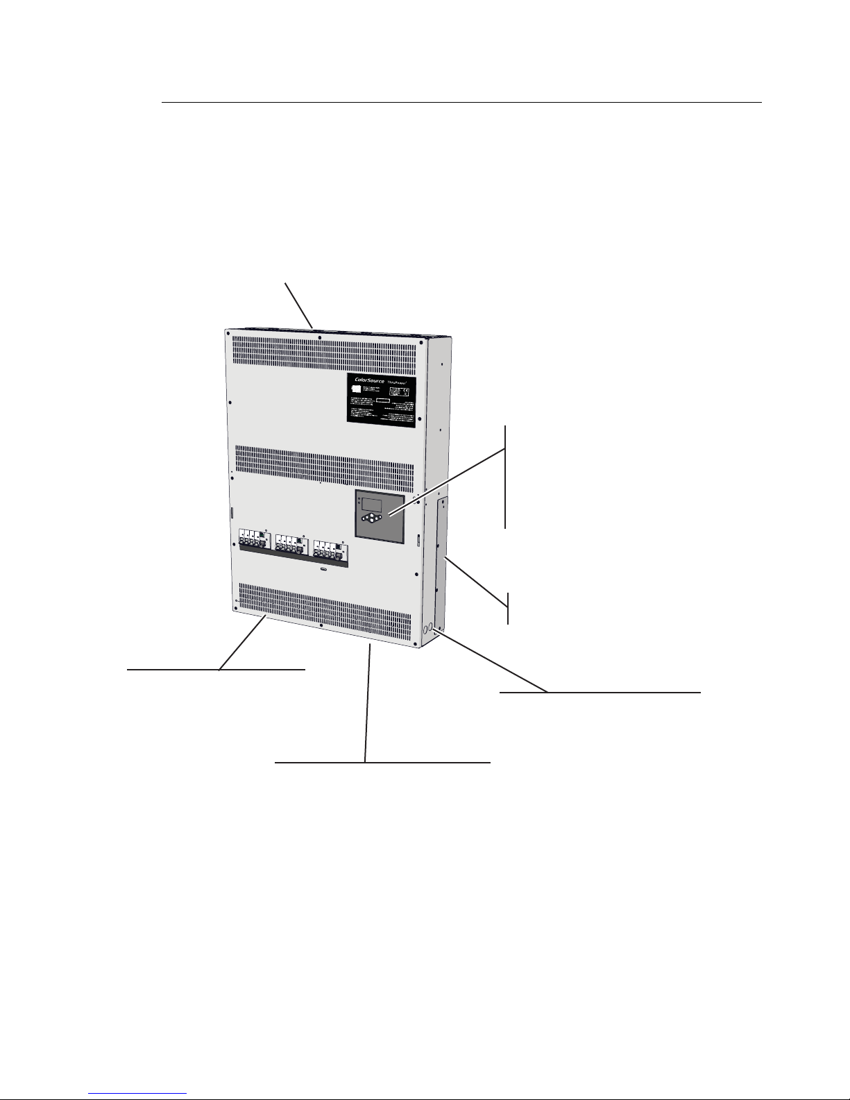
12-circuit models
Multi-language user interface display
including English, Spanish, German,
and French
User-selectable dimming curves,
including Mod Square Law, Linear,
Preheat, and Fluorescent
Removable cable entry
panels at top of enclosure
Removable cable entry
panels at sides of enclosure
Conduit knockouts low in the
left side accommodate conduit or
glands for low voltage control
wiring to the I/O compartment.
12 circuits of dimming/switching
DMX512 native device
Passive cooling for quiet operation in
low-noise environments
12 dual-pole or single-pole,
C-curve, DIN-rail mount circuit
breakers, one for each output
Emergency contact input
Removable conduit/cable gland
knockouts on bottom of enclosure.
Page 8
4 ColorSource ThruPower User Manual
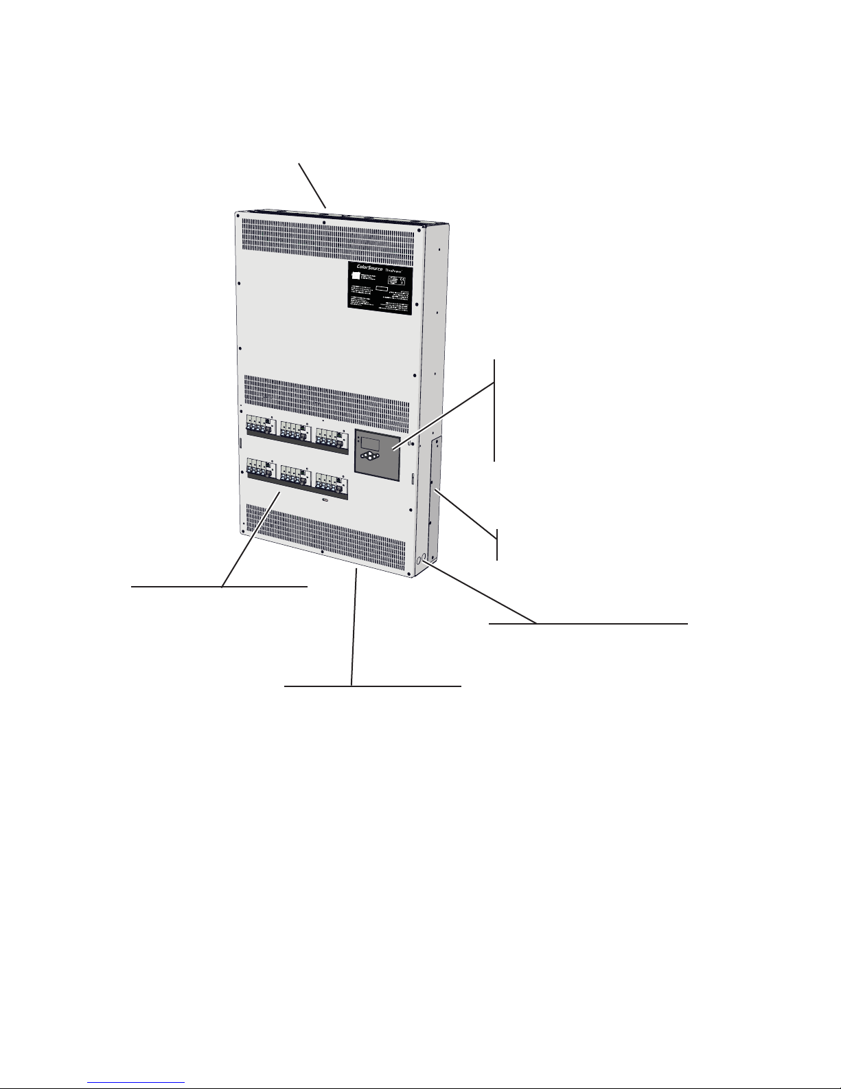
24-circuit models
Standard features
• DMX512 native device
• Passive cooling for quiet operation in low-noise environments
• Multi-language user interface display including English, Spanish, German, and French
• Removable cable entry panel at top of enclosure
• User-selectable dimming curves, including Mod Square Law, Linear, Preheat, and
Fluorescent
• Dual-pole or single-pole, C-curve, DIN-rail mount circuit breaker for each output
• Emergency contact input
Multi-language user interface display
including English, Spanish, German,
and French
User-selectable dimming curves,
including Mod Square Law, Linear,
Preheat, and Fluorescent
24 circuits of dimming/switching
DMX512 native device
Passive cooling for quiet operation in
low-noise environments
Removable cable entry
panels at top of enclosure
24 dual-pole or single-pole,
C-curve, DIN-rail mount circuit
breakers, one for each output
Emergency contact input
Removable cable entry
panels at sides of enclosure
Removable conduit/cable
gland knockouts on bottom
of enclosure.
Conduit knockouts low in the
left side accommodate conduit or
glands for low voltage control
wiring to the I/O compartment.
Page 9
Overview 5
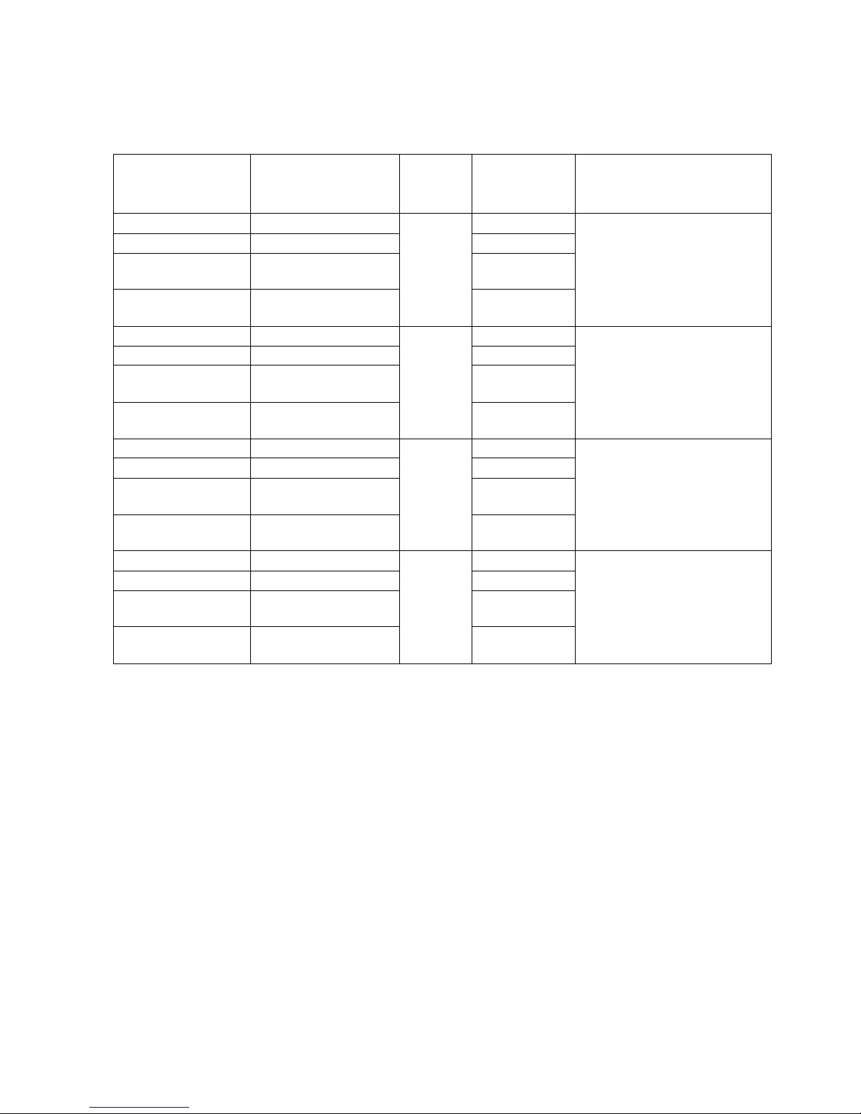
Product variants
The instructions in this manual apply specifically to the following ColorSource ThruPower
models:
Supply voltage and current
Supply Voltage: 200–265 VAC, 47-63 Hz, 3-Phase 4-wire plus protective earth.
Current per Circuit: 10 A maximum
Power supply and control
Power to the ColorSource ThruPower is supplied and protected by built-in breakers.
ColorSource models are available with 12 or 24 circuit breakers. See Product variants.
Model Part Number
Channel
Count
Breaker
Installed Weight
and
Dimensions
CSTP12 7121A1212
12
10 A SP
36 kgs with packaging
31 kgs without packaging
625 W x 819 H x 150 D mm
CSTP12-ND 7121A1212-ND 10 A ND
CSTP12-RCD 7121A1212-RCD
10 A with RCD
per 4
CSTP12-RCD+ND 7121A1212-RCD+ND
10 A ND with
RCD per 4
CSTP24 7121A1224
24
10 A SP
45 kgs with packaging
41 kgs without packaging
620 W x 1000 H x 150 D mm
CSTP24-ND 7121A1224-ND 10 A ND
CSTP24-RCD 7121A1224-RCD
10 A with RCD
per 4
CSTP24-RCD+ND 7121A1224-RCD+ND
10 A ND with
RCD per 4
CSTPro12 7121A1312
12 (Pro)
10 A SP
54 kgs with packaging
49 kgs without packaging
625 W x 819 H x 150 D mm
CSTPro12-ND 7121A1312-ND 10 A ND
CSTPro12-RCD 7121A1312-RCD
10 A with RCD
per 4
CSTPro12-RCD+ND 7121A1312-RCD+ND
10 A ND with
RCD per 4
CSTPro24 7121A1324
24 (Pro)
10 A SP
69 kgs with packaging
64 kgs without packaging
620 W x 1000 H x 150 D mm
CSTPro24-ND 7121A1324-ND 10 A ND
CSTPro24-RCD 7121A1324-RCD
10 A with RCD
per 4
CSTPro24-RCD+ND 7121A1324-RCD+ND
10 A ND with
RCD per 4
Page 10
6 ColorSource ThruPower User Manual
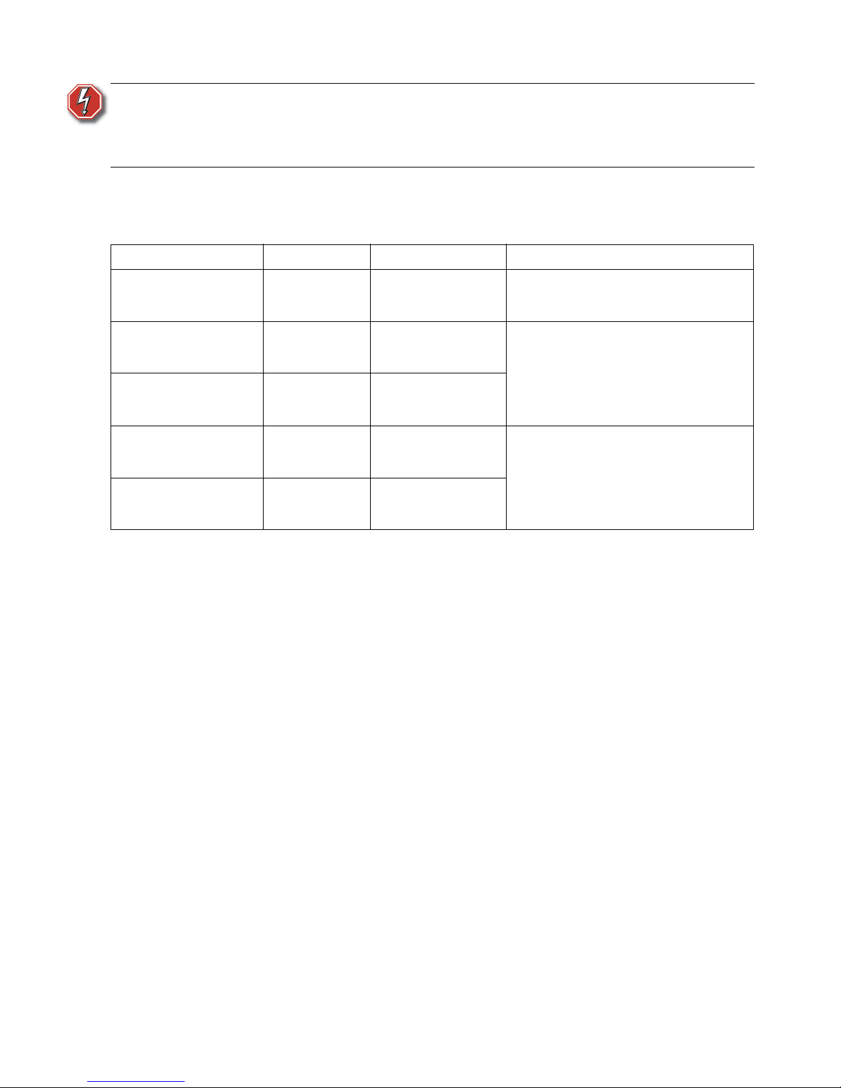
Option kits
The following option kits are available for the ColorSource ThruPower.
WARNING:
RISK OF DEATH BY ELECTRIC SHOCK! Failure to disconnect all power
to the cabinet before working inside could result in serious injury or
death. This equipment is intended to be serviced and installed by
suitably qualified personnel only.
Model Part Number Option Description
CSTP-DOOR 7121K1000 Locking Door Kit
A locking front cover that provides
controlled access to the circuit breakers
and the user interface. Field installable.
CSTP-KIT-ND-RCD-24 7121K1001
24 Channel Neutral
Disconnect Breaker
Installation Kit
Factory option only. Substitutes all
breakers in the dimmer pack for neutral
disconnect.
CSTP-KIT-ND-RCD-12 7121K1002
12 Channel Neutral
Disconnect Breaker
Installation Kit
CSTP-KIT-SP-RCD-24 7121K1003
24 Channel Single
Pole Breaker
Installation Kit
Factory or field-installable option.
Provides a 30 mA RCD for each set of 4
circuits in the dimmer pack.
CSTP-KIT-SP-RCD-12 7121K1004
12 Channel Single
Pole Breaker
Installation Kit
Page 11

Menus and configuration 7
Chapter 1
Menus and configuration
User interface
The ColorSource ThruPower user interface and menu structure provide you with an easy,
intuitive setup with built-in multiple language options.
LED indicators
Power
The power LED has four indication patterns:
• Blue LED: Indicates that the operation is normal and power is within normal parameters.
• Slow blink pattern: Indicates a problem with incoming power such as no or reduced
voltage.
• Rapid blink pattern (together with LCD backlight): The cabinet has been sent an Identify
command via RDM.
• Double blink pattern: The cabinet is in the process of upgrading firmware.
DMX
The DMX LED is a green LED with two indication patterns:
• Steady green illumination: Indicates that a DMX signal is present.
• Green LED in blinking pattern: Indicates that no DMX signal is present.
Power
DMX
Power LED
DMX LED
Keypad
LCD Screen
Page 12

8 ColorSource ThruPower User Manual
Keypad
The keypad allows you to easily navigate the menu system.
LCD
The LCD is a high-contrast, backlit display, 8 lines high and 20 characters wide.
When configuring the ColorSource ThruPower:
Navigate the menus using the [Increase] (+) or [Decrease] (–) buttons. If a complete row is
highlighted, the (+) or (–) button will move up or down through rows. If the right hand
section of a row is highlighted, using the (+) or (–) button will edit the selected value. In this
mode, press
the [Enter] () button to confirm the edit, or press the [Back] (<) button to discard
the edited value.
Adjusting the contrast of the LCD display
To adjust the contrast of the LCD display, press and hold the [Home] (<<) button while
pressing the
[Increase] (+) or [Decrease] (–) button.
LED or
Symbol
Description
Return to the home menu
Move backward one level in the menu
Accept a menu choice or store a value
Increase a value or scroll through the menu
Decrease a value or scroll through the menu
Activate the Test menu
DMX
Mode Start Address
DMX Start 1
DMX Loss Behaviour
Page 13

Menus and configuration 9
Initial power up display
The first time you apply power to the cabinet, you are asked to choose a language for the
operating system.
ThruPower configuration
Configure the ThruPower operational behaviours through the Mode menu. See “Mode” on
page 11.
Choose Language
English
Français
Deutsch
Espanol
Mode
Dimmer
Relay
TPAuto
Always On
Off
Page 14

10 ColorSource ThruPower User Manual
Menu structure
Home screen
Following initial start-up and the selection of a language, the Home screen becomes the
primary display when the ColorSource ThruPower is turned on. From anywhere in the menu
system, you can return to the Home screen at any time by pressing the
[Home] (<<) button.
The display also returns to the Home screen after 2 minutes of inactivity.
The Home screen displays the following:
Bargraph – Shows active dimmer levels. Shows 12 or 24 bars, depending on the
ColorSource model.
System Status – Shows one of three conditions:
• System OK – The system is operating normally
• Temperature High – System is in a high-temperature condition
• Emergency Active – Emergency Input is active
DMX Mode – Shows one of two conditions:
• DMX Start = [start address] – System is in Start Address mode
• DMX Patch – System is in Patched mode
Power Status – Shows the status of the incoming three power phases (L1, L2, and L3)
• OK – Output is detected OK
• ERR – The phase is missing or is outside of the acceptable voltage and frequency for
the cabinet
Software Version – The ColorSource ThruPower’s current software version
WARNING:
If an overtemperature condition is displayed, the internal heatsinks have
reached 100° Celsius. Ensure that the exterior of the product is properly
cooled:
• The ambient temperature surrounding the cabinet must not exceed 40°
Celsius.
• The cabinet must be provided adequate airflow.
• The vents must not be obstructed.
Once the overtemperature condition is corrected, the error should clear. If
the error persists, contact ETC Technical Services for assistance.
ColorSource ThruPower
System OK
DMX Start = 1
L1: OK L2: OK L3: OK
V1.0.0.0.0.13
Bargraph
System Status
DMX Mode
Software Version
Output Status
Page 15

Menu structure 11
Settings menu
You can open the Settings menu from the Home screen by pressing any button. Through the
Settings menu you can open any of three configuration menus or view system version
numbers.
DMX
Used to set DMX-related parameters.
Output Setup
Used to set output-related parameters.
General Settings
Used to configure standard features of the ColorSource ThruPower cabinet.
About
Displays the current software versions.
DMX
The DMX menu is used to set the DMX mode and related parameters, as well as the DMX loss
behavior.
Mode
The Mode menu allows you to switch between Start Address and Patch. To select the mode:
Step 1: Scroll to Mode and then press the [Enter] (
) button.
Step 2: Press the [Increase] (+) or [Decrease] (–) button to scroll between the two
menu options, "Start Address" or "Patch".
Step 3: Press the [Enter] (
) button to set the mode option.
Settings
DMX
Output Setup
General Settings
About
DMX
Mode Start Address
DMX Start 1
DMX Loss Behaviour
Page 16

12 ColorSource ThruPower User Manual
DMX Start
"DMX Start" and the start address are displayed if you selected the "Start Address" menu
option in the Mode menu. The start address range is 001–512, minus the cabinet output
count. Set the DMX start address as follows:
Step 1: Scroll to DMX Start and then press the [Enter] (
) button.
Step 2: Press the [Increase] (+) or [Decrease] (–) button to increment or decrement the
start address range.
Step 3: Press the [Enter] (
) button to set the start address.
Step 4: When finished, press the [Back] (<) button to return to the previous menu, or
press the [Home] (<<) button to return to the Home screen, where you can
confirm that "DMX Start" is displayed as the active DMX mode.
DMX Patch
"DMX Patch" is displayed if you selected the "Patch" menu option in the Mode menu. DMX
Patch allows you to patch different DMX addresses to selected dimmers. You use this menu
whenever setting the DMX start address is not sufficient. To change the DMX patch
parameters:
Step 1: Scroll to DMX Patch and then press the [Enter] (
) button.
Step 2: Scroll to Output and then press the [Enter] (
) button.
Step 3: Use the [Increase] (+) or [Decrease] (–) button to select a higher or lower
dimmer channel. Dimmers are numbered 1–12 or 1–24, depending on the
ColorSource ThruPower channel count. Initially, the DMX address is patched
consecutively with the dimmer channel. If the DMX address should differ from
the dimmer channel number, press the [Enter] (
) button.
Step 4: Press the [Increase] (+) or [Decrease] (–) button to scroll through the range of
dimmer channels.
Step 5: Press the [Enter] (
) button to set the dimmer channel number.
Step 6: Scroll to DMX Address and then press the [Enter] (
) button.
Step 7: Press the [Increase] (+) or [Decrease] (–) button to scroll through the range of
DMX addresses.
Step 8: Press the [Enter] (
) button to set the DMX address.
Step 9: Continue with steps 2 through 8 until all dimmers are patched to the required
DMX Address.
Step 10: When finished, press the [Back] (<) button to return to the previous menu, or
press the [Home] (<<) button to return to the Home screen, where you can
confirm that "DMX Patch" is displayed as the active DMX mode.
DMX Patch
Output: 1
DMX Address: 1
Page 17

Menu structure 13
DMX Loss Behavior
The DMX Loss Behaviour menu allows you to set the behavior of the dimmers when data
communication is lost.
Mode
In the "Mode" menu option, select the loss behavior as follows:
Step 1: Press the [Enter] (
) button.
Step 2: Use the [Increase] (+) or [Decrease] (–) button to highlight the desired loss
behavior:
• Hold Last Look – Holds the active dimmers at whatever levels they were
receiving when the data was lost. The dimmers remain on until either data
is restored or the cabinet is reset.
• Wait and Fade – Holds active dimmers for a span of time, at whatever levels
they were receiving when the data was lost, and then fades those dimmers
to zero in a defined fade time. You can define both the wait time and the
fade time, within a maximum of 59min:59sec.
Step 3: Press the [Enter] (
) button.
Wait
When "Wait and Fade" is selected, this menu option allows you to set the time span for
holding the dimmer levels before fading. To change the wait time:
Step 1: Press the [Enter] (
) button.
Step 2: Use the [Increase] (+) or [Decrease] (–) button to set the minutes value, and
then press the [Enter] (
) button. Repeat for the seconds value.
Step 3: Press the [Enter] (
) button.
Fade
When "Wait and Fade" is selected, this menu option allows you to set the time span over
which the dimmers fade to zero. To change the fade time:
Step 1: Press the [Enter] (
) button.
Step 2: Use the [Increase] (+) or [Decrease] (–) button to set the minutes value, and
then press the [Enter] (
) button. Repeat for the seconds value.
Step 3: Press the [Enter] (
) button.
When finished, press the
[Back] (<) button to return to the previous menu, or press the
[Home] (<<) button to return to the Home screen.
DMX Loss Behaviour
Mode: Hold Last Look
Wait: 0 min 3 sec
Fade: 0 min 3 sec
Page 18

14 ColorSource ThruPower User Manual
From Dimmer
The From Dimmer menu allows you to select the dimmers for which you will configure the
output. To select the dimmers:
Step 1: Scroll to From Dimmer and then press the [Enter] (
) button.
Step 2: Press the [Increase] (+) or [Decrease] (–) button to scroll through the dimmer
numbers, and then press the [Enter] (
) button to set the first dimmer in the
range.
Step 3: Repeat the preceding step to set the last dimmer in the range.
Dimmer
The output will dim according to the curve setting selected in the dimmer Curve menu (see
on page 14). The relay will not close at any level, including at full.
Relay
While the control level is below the threshold configured in the Threshold menu, the relay is
switched off. When the control level reaches the threshold, the relay is switched on. See
“Threshold” on page 16..
TPAuto
With ThruPower, dimming is operated between the DMX levels of 0 and 254, while latching
the relay at DMX level 255. TPAuto can be used to allow the configuration of dimming verses
relay mode, which can be stored as part of console show files for consoles that do not have
RDM functionality available.
Output Setup
From Dimmer: 1 to 1
Mode: Dimmer
Curve: Mod-Square
Emergency Yes
Threshold 1%
Output Setup
The Output Setup menu is used to set circuitrelated parameters.
Mode
Dimmer
Relay
TPAuto
Always On
Off
Mode
The Mode menu allows you to select and apply
the output mode to the selected circuits.
Curve
Mod-Square
Linear
Preheat
Fluorescent
Curve
The Curve menu allows you to select and apply one
of four curves.
Page 19

Menu structure 15
The ColorSource ThruPower is capable of dimming or switching multiple load types, including
incandescent, low voltage, and 2-wire fluorescent. You can choose from four output curves:
Output Voltage
10%
20%
30%
40%
50%
60%
70%
80%
90%
100%
Control Input
0% 100%
Output Voltage
10%
20%
30%
40%
50%
60%
70%
80%
90%
100%
Control Input
0% 100%
Output Voltage
10%
20%
30%
40%
50%
60%
70%
80%
90%
100%
Control Input
0% 100%
Output Voltage
10%
20%
30%
40%
50%
60%
70%
80%
90%
100%
Control Input
0% 100%
Mod-Square: The mod-square curve
provides a non-linear relationship between
control level and voltage. For most tungsten
lamps, this provides the best relationship
between brightness and level, and is the
default.
Linear: The linear curve
provides a linear relationship
between input control level
and output voltage
Fluorescent: The fluorescent curve
provides a linear curve which steps to 46%
level when the level is raised above zero –
this is helpful with dimmable fluorescents
and other non-tungsten loads. This initial
voltage is 47% of the incoming voltage.
Preheat: The preheat curve
provides a fixed preheat at 5% of
the incoming voltage (12V assuming
a 230V input). Preheat is used to
extend lamp life when lamps are
being turned on rapidly from cold.
Page 20

16 ColorSource ThruPower User Manual
Emergency
The Emergency menu option allows you to configure the ColorSource ThruPower’s
emergency contact input. When an active emergency contact is received, all non-emergency
dimmers in the cabinet are forced off, while all user-selected emergency dimmers are driven
to full.
When an emergency contact input is active, the LCD displays a message advising “Emergency
Active,” and the menu locks out all access to the system. After normal power is restored, the
cabinet resumes normal operation.
Activate the emergency contact input as follows:
Step 1: After selecting the dimmers, scroll to the Emergency menu option and then press
the [Enter] (
) button.
Step 2: Use the [Increase] (+) or [Decrease] (–) button to scroll between "Yes" or
"No", and then press the [Enter] (
) button.
Threshold
The Threshold menu option allows you to set the percentage level at which the relay switches
on, within a range of 1-99% when the circuit is in relay mode. The default value is 1%.
General Settings
The General Settings menu is used to configure standard features of your ColorSource
ThruPower dimmer pack.
BackLight
To configure the LCD backlight:
Step 1: From the General Settings menu navigate to Backlight.
Step 2: Press the [Enter] (
) button.
Step 3: Use the [Increase] (+) or [Decrease] (–) button to set the backlight mode:
• Auto – LCD dims when not in use for a period of time
• Off – Always off
• On – Always on
Step 4: Press the [Enter] (
) button.
General Settings
Backlight Auto
Language English
Restore Defaults
Page 21

Menu structure 17
Language
The Language menu allows you to select from multiple language options:
Step 1: Press the [Enter] (
) button.
Step 2: Use the [Increase] (+) or [Decrease] (–) button to highlight the language:
• English
• Français (French)
•Deutsch (German)
• Español (Spanish)
Step 3: Press the [Enter] (
) button.
Restore Defaults
Resets the following attributes to default status:
• Dimmer Curves – Set to Mod SQR Law
• DMX Start Address – Set to the start address 1–12 or 1–24, depending on ColorSource
model
• DMX Loss Behavior – Reset to Hold Last Look
Yes
With the "Yes" menu item highlighted, press the
[Enter] () button to restore the above
attributes to default status.
No
To avoid resetting the above attributes to default, highlight the "No" menu option and then
press the
[Enter] () button. Optionally, press the [Back] (<) button to return to the previous
menu.
Restore Defaults
Are you sure? This
will restore all
settings to factory
defaults.
Yes
No
Page 22

18 ColorSource ThruPower User Manual
About
Test menu
The Test menu is a tool for testing dimmers and loads. In the absence of a DMX control
source, the test menu may also be used to set dimmer levels to snapshot a preset.
Enter the Test menu
From any menu, press the [Test] button.
Set dimmer levels in the Test menu
For testing, you can set all dimmers to the same level, or set dimmers individually or in groups
to different levels.
To set all dimmers to the same level:
Step 1: In the "Dimmer" menu option, all dimmers are selected by default, either "1
thru 12" or "1 thru 24", depending on the ColorSource model.
Step 2: In the "Level" menu uption, "100%" is set by default. To change the level, press
the [Enter] (
) button and then the [Increase] (+) or [Decrease] (–) button.
When finished, press the [Enter] (
) button.
Step 3: In the "Set" menu option, press the [Enter] (
) button. This activates the
dimmers you chose, at the level you selected. This can be verified on the Home
screen, by pressing the [Home] (<<) button.
About
Version 1.0.0.0.0.13
DimEng 1.0.0.2
RDM ID 6874:ABCDE00F
Serial 4500000123
Triac Board 1 12
Triac Board 2 -
Version
Displays the current software version.
DimEng (Dimming Engine)
Displays the current Dimming Engine version.
RDM ID
Displays the ID of the current RDM device
connected
Serial
Displays the serial number
Triac Board 1 and 2
Displays the version number, or a dash if not found.
Test
Dimmer 1 thru 24
Level 100%
Set
Release All
Page 23

Menu structure 19
To set groups of dimmers to different levels:
Step 1: In the "Dimmer" menu option, all dimmers are selected by default, either "1
thru 12" or "1 thru 24", depending on the ColorSource model. To select a range
of dimmers, press the [Enter] (
) button and then press the [Increase] (+) or
[Decrease] (–) button to set the first dimmer. Press the [Enter] (
) button again
and then set the last dimmer in the range, using the [Increase] (+) or [Decrease]
(–) button. When finished, press the [Enter] (
) button
Step 2: In the "Level" menu uption, "100%" is set by default. To change the level, press
the [Enter] (
) button and then the [Increase] (+) or [Decrease] (–) button.
When finished, press the [Enter] (
) button.
Step 3: In the "Set" menu option, press the [Enter] (
) button.
Step 4: Repeat steps 1 through 3 to set the remaining groups of dimmers.
Step 5: This activates the groups dimmers you chose, at the levels you selected. This can
be verified on the Home screen, by pressing the [Home] (<<) button.
To set individual dimmers to different levels:
Step 1: In the "Dimmer" menu option, all dimmers are selected by default, either "1
thru 12" or "1 thru 24", depending on the ColorSource model. To select an
individual dimmer, set the first and last dimmers to the same number.
Step 2: Highlight the "Dimmer" menu option. Press the [Enter] (
) button and then the
[Increase] (+) or [Decrease] (–) button to select the dimmer. Press the [Enter]
(
) button again to set the end of range, and press the [Increase] (+) or
[Decrease] (–) button to select the same number. For example, setting both start
and end of range numbers to "1" selects dimmer #1, individually. When
finished, press the [Enter] (
) button
Step 3: In the "Level" menu uption, "100%" is set by default. To change the level, press
the [Enter] (
) button and then the [Increase] (+) or [Decrease] (–) button.
When finished, press the [Enter] (
) button.
Step 4: In the "Set" menu option, press the [Enter] (
) button.
ColorSource ThruPower
System OK
DMX Start = 1
L1: OK L2: OK L3: OK
V1.0.0.0.0.13
ColorSource ThruPower
System OK
DMX Start = 1
L1: OK L2: OK L3: OK
V1.0.0.0.0.13
Page 24

20 ColorSource ThruPower User Manual
Step 5: Repeat steps 1 through 4 to set the remaining dimmers.
Step 6: This activates the dimmers at the levels you selected. This can be verified on the
Home screen, by pressing the [Home] (<<) button.
Exit the test
To end the test:
Step 1: In the "Dimmer" menu option, press the [Enter] () button and then the
[Increase] (+) or [Decrease] (–) button to set the start of range to "1".
Step 2: Press the [Enter] (
) button and then the [Increase] (+) or [Decrease] (–)
button to set the end of range to the total number of dimmers, either "12" or
"24". When finished, press the [Enter] (
) button.
Step 3: Highlight the "Release All" menu option and then press the [Enter] (
) button.
Step 4: This turns off all the dimmers, ending the test. This can be verified on the Home
screen, by pressing the [Home] (<<) button.
ColorSource ThruPower
System OK
DMX Start = 1
L1: OK L2: OK L3: OK
V1.0.0.0.0.13
ColorSource ThruPower
System OK
DMX Start = 1
L1: OK L2: OK L3: OK
V1.0.0.0.0.13
Page 25

Service and maintenance 21
Appendix A
Service and maintenance
To contact ETC Service, refer to Help from ETC Technical Services on page 2.
Maintenance
Vacuum the vents
Vacuum the dust from the airflow vents regularly. The interval between cleanings is
dependent on the amount of dust and other contaminants present in the installation
environment. Never allow the vents to become completely blocked with dust.
Vacuum the interior
Step 1: Disconnect power from the ColorSource ThruPower.
Step 2: Remove the front cover of the cabinet and detach the ground wire.
Step 3: Vacuum dust from the interior of the cabinet. Use compressed air from a can to
blow dust from the circuit boards to avoid possible damage from electrostatic
discharge.
Step 4: Before applying power to the cabinet, ensure that the ground wire is reattached
to the front cover and then reinstall the front cover.
WARNING:
RISK OF DEATH BY ELECTRIC SHOCK! Failure to disconnect all
power to the cabinet before working inside could result in
serious injury or death. This equipment is intended to be
serviced and installed by suitably qualified personnel only.
Page 26

22 ColorSource ThruPower User Manual
Replacement parts
The following field-replaceable parts are used in the ColorSource ThruPower. Field
replacements are available from ETC or may be purchased at your local electrical supply
house.
For all other field issues, please contact ETC technical services for assistance.
Location Part ETC Part Number
Power Input Board, Location F1 Fuse, 2A 250V F 5x20mm F149
Triac Boards, Locations J1-J12 Alternistor, 40A 800V Q325-F
Control Board, Chip U10 DMX Transceiver 75LBC182 Z1458-F
Page 27

Troubleshooting 23
Troubleshooting
Isolate and correct faults in the ColorSource ThruPower, according to the following.
No Output to the Loads
• Ensure that correct power is supplied to the cabinet, and that the power cables are
properly connected.
• Check that the DMX LED shows steady green illumination, indicating that a stable DMX
signal is present. A blinking pattern indicates that no DMX signal is present. If the LED
is blinking, check the DMX connections according to the ColorSource ThruPower
Installation Manual.
• Check that the power LED shows steady blue illumination. A blinking pattern indicates
a problem with the incoming power supply. Check the supply with the assistance of a
suitably qualified electrician.
• Check that the cabinet is not in over-temperature mode. If the display shows overtemp,
cool the cabinet appropriately until outputs turn back on.
Outputs cannot be dimmed
• Ensure that the incoming power to the cabinet is on (verify that Power LED is not
blinking).
• Ensure that the outputs are configured for Dimmer mode (not Relay or TPAuto). For
more on configuring outputs, see ThruPower configuration on page 9
Outputs cannot be turned off
• Ensure that the bar graph on the home screen displays the expected levels for the
outputs.
• If the bar graph shows zero but the output is still on, you may have a failed triac. Consult
a qualified service person to have the triac replaced, or contact ETC technical services.
WARNING:
If an overtemperature condition is displayed, the internal heatsinks
have reached 100° C. Ensure that the exterior of the product is
properly cooled:
• The ambient temperature surrounding the cabinet must not
exceed 40° Celsius.
• The cabinet must be provided adequate airflow.
• The vents must not be obstructed.
Once the overtemperature condition is corrected, the error should
clear. If the error persists, contact ETC Technical Services for
assistance.
Page 28

24 ColorSource ThruPower User Manual
Page 29

Menu flow chart 25
Appendix B
Menu flow chart
First Time Power Up Display
Choose Language
English
Français
Deutsch
Español
ColorSource ThruPower
System OK
DMX Start = 1
L1: OK L2: OK L3: OK
V1.0.0.0.0.13
Home Screen
Bar Graph
Shows active dimmer levels, as
many as 12 or 24, depending
on the ColorSource model.
Output Status
OK = Detected OK
ERR = Not detected, or Off
Software Version
System Status
System is operating normally:
In Temp High condition:
When Emergency Input Is active:
Temperature High!
System OK
Emergency Active
DMX Mode
In Start Address mode:
In Patched mode:
DMX Start = xxx
DMX Patch
Test Menu
Test
Dimmer 1 thru 24
Level 100%
Set
Release All
Keypad
Buttons
Return to the home screen
Move backward one menu
level
Accept the menu choice or
store a value
Increase a value or scroll
upward through the menu
Decrease a value or scroll
downward through the menu
Activate the Test menu
Page 30

26 ColorSource ThruPower User Manual
DMX
Mode Start Address
DMX Start 1
DMX Loss Behaviour
DMX Loss Behaviour
Mode: Hold Last Look
Wait: 0 min 3 sec
Fade: 0 min 3 sec
DMX Loss Behaviour
Mode: Wait and Fade
Wait: 0 min 3 sec
Fade: 0 min 3 sec
OR
OR
ColorSource ThruPower
System OK
DMX Start = 1
L1: OK L2: OK L3: OK
V1.0.0.0.0.13
Settings
DMX
Output Setup
General Settings
About
DMX
Mode Start Address
DMX Start 1
DMX Loss Behaviour
DMX Patch
Output: 1
DMX Address: 1
DMX
Mode Patched
DMX Patch
DMX Loss Behaviour
A
Press any button
on keypad
Page 31

Menu flow chart 27
Output Setup
From Dimmer: 1 to 1
Mode: Dimmer
Curve: Mod-Square
Emergency Yes
Threshold 1%
Curve
Mod-Square
Linear
Preheat
Fluorescent
Mode
Dimmer
Relay
TPAuto
Always On
Off
General Settings
Backlight Auto
Language English
Blanking (us): 500
Restore Defaults
About
Version 1.0.0.0.0.13
DimEng 1.0.0.2
RDM ID 6874:ABCDE00F
Serial 4500000123
Triac Board 1 12
Triac Board 2 -
Restore Defaults
Are you sure? This
will restore all
settings to factory
defaults.
Yes
No
A
Page 32

Corporate Headquarters Middleton, WI, USA Tel +608 831 4116 Service: (Americas)
service@etcconnect.com
London, UK Tel +44 (0)20 8896 1000 Service: (UK)
service@etceurope.com
Rome, IT Tel +39 (06) 32 111 683 Service: (UK)
service@etceurope.com
Holzkirchen, DE Tel +49 (80 24) 47 00-0 Service: (DE)
techserv-hoki@etcconnect.com
Hong Kong Tel +852 2799 1220 Service: (Asia)
service@etcasia.com
Web:
www.etcconnect.com
Copyright © 2015 ETC. All Rights Reserved.
7121M1200-1.0.0
Rev A Released 2015-12 Product information and specifications subject to change.
 Loading...