

Page 1

ES920.1
FlexRay Module
User’s Guide
Page 2

Copyright
The data in this document may not be altered or amended without special notification from ETAS GmbH. ETAS GmbH undertakes no further obligation in relation to this document. The software described in it can only be used if the
customer is in possession of a general license agreement or single license. Using
and copying is only allowed in concurrence with the specifications stipulated in
the contract.
Under no circumstances may any part of this document be copied, reproduced,
transmitted, stored in a retrieval system or translated into another language
without the express written permission of ETAS GmbH.
© Copyright 2019 ETAS GmbH, Stuttgart
The names and designations used in this document are trademarks or brands
belonging to the respective owners.
ES920.1 - User’s Guide R07 EN - 02.2019
2
Page 3

ETAS Contents
Contents
1 About this Manual . . . . . . . . . . . . . . . . . . . . . . . . . . . . . . . . . . . . . . . . . . . . . . . . . 6
1.1 Identification of Safety Notices . . . . . . . . . . . . . . . . . . . . . . . . . . . . . . . . . . . 6
1.2 Presentation of Information . . . . . . . . . . . . . . . . . . . . . . . . . . . . . . . . . . . . . 6
1.3 Scope of Supply . . . . . . . . . . . . . . . . . . . . . . . . . . . . . . . . . . . . . . . . . . . . . . 7
1.4 Additional Information . . . . . . . . . . . . . . . . . . . . . . . . . . . . . . . . . . . . . . . . . 7
2 Basic Safety Notices . . . . . . . . . . . . . . . . . . . . . . . . . . . . . . . . . . . . . . . . . . . . . . . . 8
2.1 General Safety Information . . . . . . . . . . . . . . . . . . . . . . . . . . . . . . . . . . . . . . 8
2.2 Requirements for Users and Duties for Operators . . . . . . . . . . . . . . . . . . . . . 8
2.3 Intended Use . . . . . . . . . . . . . . . . . . . . . . . . . . . . . . . . . . . . . . . . . . . . . . . . 8
3 Hardware Description . . . . . . . . . . . . . . . . . . . . . . . . . . . . . . . . . . . . . . . . . . . . . . 14
3.1 Overview . . . . . . . . . . . . . . . . . . . . . . . . . . . . . . . . . . . . . . . . . . . . . . . . . . 14
3.1.1 FlexRay . . . . . . . . . . . . . . . . . . . . . . . . . . . . . . . . . . . . . . . . . . . . . 14
3.1.2 Definitions. . . . . . . . . . . . . . . . . . . . . . . . . . . . . . . . . . . . . . . . . . . 15
3.2 ES920.1 . . . . . . . . . . . . . . . . . . . . . . . . . . . . . . . . . . . . . . . . . . . . . . . . . . . 16
3.2.1 Features . . . . . . . . . . . . . . . . . . . . . . . . . . . . . . . . . . . . . . . . . . . . 16
3.2.2 View of the Module. . . . . . . . . . . . . . . . . . . . . . . . . . . . . . . . . . . . 18
3.2.3 Ports . . . . . . . . . . . . . . . . . . . . . . . . . . . . . . . . . . . . . . . . . . . . . . . 18
3.2.4 LEDs . . . . . . . . . . . . . . . . . . . . . . . . . . . . . . . . . . . . . . . . . . . . . . . 18
4 Functional Description. . . . . . . . . . . . . . . . . . . . . . . . . . . . . . . . . . . . . . . . . . . . . . 19
4.1 Block Diagram . . . . . . . . . . . . . . . . . . . . . . . . . . . . . . . . . . . . . . . . . . . . . . 19
4.2 Bus Termination Resistor . . . . . . . . . . . . . . . . . . . . . . . . . . . . . . . . . . . . . . . 19
4.3 “Wake Up” and “Sleep” Functions . . . . . . . . . . . . . . . . . . . . . . . . . . . . . . . 19
4.3.1 “Wake Up” Function. . . . . . . . . . . . . . . . . . . . . . . . . . . . . . . . . . . 20
4.3.2 “Sleep” Function. . . . . . . . . . . . . . . . . . . . . . . . . . . . . . . . . . . . . . 21
4.3.3 Configuration . . . . . . . . . . . . . . . . . . . . . . . . . . . . . . . . . . . . . . . . 21
4.4 Firmware . . . . . . . . . . . . . . . . . . . . . . . . . . . . . . . . . . . . . . . . . . . . . . . . . . 21
4.4.1 ES920.1 Firmware . . . . . . . . . . . . . . . . . . . . . . . . . . . . . . . . . . . . 21
ES920.1 - User’s Guide 3
Page 4

ETAS Contents
4.4.2 Firmware Update. . . . . . . . . . . . . . . . . . . . . . . . . . . . . . . . . . . . . . 21
5 Getting Started . . . . . . . . . . . . . . . . . . . . . . . . . . . . . . . . . . . . . . . . . . . . . . . . . . . 22
5.1 Assembly . . . . . . . . . . . . . . . . . . . . . . . . . . . . . . . . . . . . . . . . . . . . . . . . . . 22
5.1.1 Removing the Front Panel of the ES910 Extension Slot. . . . . . . . . . 22
5.1.2 Installing the ES920.1 in the ES910 Module. . . . . . . . . . . . . . . . . . 23
5.2 Disassembly . . . . . . . . . . . . . . . . . . . . . . . . . . . . . . . . . . . . . . . . . . . . . . . . 25
5.2.1 Removing the ES920.1 from the ES910 Module. . . . . . . . . . . . . . . 25
5.2.2 Attaching the Front Panel of the ES910 Extension Slot. . . . . . . . . . 26
5.3 Applications . . . . . . . . . . . . . . . . . . . . . . . . . . . . . . . . . . . . . . . . . . . . . . . . 27
5.3.1 Function Development for FlexRay ECUs . . . . . . . . . . . . . . . . . . . . 27
5.3.2 Gateway Function between CAN and FlexRay Buses . . . . . . . . . . . 27
5.4 Wiring . . . . . . . . . . . . . . . . . . . . . . . . . . . . . . . . . . . . . . . . . . . . . . . . . . . 28
5.5 Configuring the ES920.1 . . . . . . . . . . . . . . . . . . . . . . . . . . . . . . . . . . . . . . 29
5.5.1 Web Interface . . . . . . . . . . . . . . . . . . . . . . . . . . . . . . . . . . . . . . . . 29
5.5.2 Configuring the “Wake Up” Function of the ES920.1 Module. . . . 29
5.6 Troubleshooting . . . . . . . . . . . . . . . . . . . . . . . . . . . . . . . . . . . . . . . . . . . . . 30
6 Technical Data . . . . . . . . . . . . . . . . . . . . . . . . . . . . . . . . . . . . . . . . . . . . . . . . . . . 31
6.1 General Data . . . . . . . . . . . . . . . . . . . . . . . . . . . . . . . . . . . . . . . . . . . . . . . 31
6.1.1 Identifications on the Product . . . . . . . . . . . . . . . . . . . . . . . . . . . . 31
6.2 Fulfilled Standards and Norms . . . . . . . . . . . . . . . . . . . . . . . . . . . . . . . . . . . 31
6.3 RoHS Conformity . . . . . . . . . . . . . . . . . . . . . . . . . . . . . . . . . . . . . . . . . . . . 32
6.3.1 European Union . . . . . . . . . . . . . . . . . . . . . . . . . . . . . . . . . . . . . . 32
6.3.2 China . . . . . . . . . . . . . . . . . . . . . . . . . . . . . . . . . . . . . . . . . . . . . . 32
6.4 CE marking . . . . . . . . . . . . . . . . . . . . . . . . . . . . . . . . . . . . . . . . . . . . . . . . . 32
6.5 Product return and recycling . . . . . . . . . . . . . . . . . . . . . . . . . . . . . . . . . . . . 32
6.6 Use of Open Source Software . . . . . . . . . . . . . . . . . . . . . . . . . . . . . . . . . . . 33
6.7 System Requirements . . . . . . . . . . . . . . . . . . . . . . . . . . . . . . . . . . . . . . . . . 33
6.7.1 Hardware . . . . . . . . . . . . . . . . . . . . . . . . . . . . . . . . . . . . . . . . . . . 33
6.7.2 Software . . . . . . . . . . . . . . . . . . . . . . . . . . . . . . . . . . . . . . . . . . . . 33
6.7.3 ES920.1 Firmware . . . . . . . . . . . . . . . . . . . . . . . . . . . . . . . . . . . . 34
6.7.4 Environmental Conditions . . . . . . . . . . . . . . . . . . . . . . . . . . . . . . . 34
6.7.5 Mechanical Data . . . . . . . . . . . . . . . . . . . . . . . . . . . . . . . . . . . . . . 34
6.8 Electrical Data . . . . . . . . . . . . . . . . . . . . . . . . . . . . . . . . . . . . . . . . . . . . . . . 35
6.8.1 Power Supply . . . . . . . . . . . . . . . . . . . . . . . . . . . . . . . . . . . . . . . . 35
6.8.2 FlexRay Module . . . . . . . . . . . . . . . . . . . . . . . . . . . . . . . . . . . . . . . 35
6.9 Pin Assignment . . . . . . . . . . . . . . . . . . . . . . . . . . . . . . . . . . . . . . . . . . . . . . 36
7 Cables and Accessories . . . . . . . . . . . . . . . . . . . . . . . . . . . . . . . . . . . . . . . . . . . . . 37
7.1 FlexRay Interface Cable . . . . . . . . . . . . . . . . . . . . . . . . . . . . . . . . . . . . . . . . 37
7.2 FlexRay Interface Termination Resistor . . . . . . . . . . . . . . . . . . . . . . . . . . . . . 38
8 Ordering Information . . . . . . . . . . . . . . . . . . . . . . . . . . . . . . . . . . . . . . . . . . . . . . 39
8.1 ES920.1 . . . . . . . . . . . . . . . . . . . . . . . . . . . . . . . . . . . . . . . . . . . . . . . . . . . 39
8.2 Accessories . . . . . . . . . . . . . . . . . . . . . . . . . . . . . . . . . . . . . . . . . . . . . . . . . 39
8.2.1 FlexRay Interface Cable . . . . . . . . . . . . . . . . . . . . . . . . . . . . . . . . . 39
8.2.2 Termination Resistor . . . . . . . . . . . . . . . . . . . . . . . . . . . . . . . . . . . 39
8.2.3 Spare Screws. . . . . . . . . . . . . . . . . . . . . . . . . . . . . . . . . . . . . . . . . 39
ES920.1 - User’s Guide 4
Page 5

ETAS Contents
9 ETAS Contact Addresses . . . . . . . . . . . . . . . . . . . . . . . . . . . . . . . . . . . . . . . . . . . . 40
Figures . . . . . . . . . . . . . . . . . . . . . . . . . . . . . . . . . . . . . . . . . . . . . . . . . . . . . . . . . 41
Index . . . . . . . . . . . . . . . . . . . . . . . . . . . . . . . . . . . . . . . . . . . . . . . . . . . . . . . . . . 43
ES920.1 - User’s Guide 5
Page 6
ETAS About this Manual
1 About this Manual
This chapter contains information about the following topics:
• "Identification of Safety Notices" on page 6,
• "Presentation of Information" on page 6,
• "Scope of Supply" on page 7,
• "Additional Information" on page 7.
1.1 Identification of Safety Notices
The safety notices contained in this manual are identified with the danger symbol
shown below:
The safety notices shown below are used for this purpose. They provide notes to
extremely important information. Please read this information carefully.
DANGER!
indicates an immediate danger with a high risk of death or serious
injury, if not avoided.
WARNING!
indicates a possible danger with moderate risk of death or (serious)
injury, if not avoided.
CAUTION!
identifies a hazard with low risk that could result in minor or medium
physical injuries or property damages if not avoided.
1.2 Presentation of Information
All activities to be performed by the user are presented in a "Use Case" format.
That is, the goal to be accomplished is briefly defined in the heading, and the
respective steps required for reaching this goal are then presented in a list. The
presentation looks as follows:
Goal definition:
any advance information...
• Step 1
Any explanation for step 1...
• Step 2
Any explanation for step 2...
• Step 3
Any explanation for step 3...
ES920.1 - User’s Guide 6
Page 7

ETAS About this Manual
Any concluding comments...
Typographical conventions
The following typographical conventions are used:
Bold Labels of the device
Italic Particularly important text passages
Important notes for the user are presented as follows:
Note
Important note for the user.
1.3 Scope of Supply
Prior to the initial commissioning of the module, please check whether the module was delivered with all required components and cables (see chapter 8.1
on page 39).
Additional cables and adapters can be obtained separately from ETAS. A list of
available accessories and their order designation is located in chapter "Accessories" on page 39 of this manual or in the ETAS product catalog.
1.4 Additional Information
The configuration instructions for the module under INCA can be found in the
corresponding software documentation.
ES920.1 - User’s Guide 7
Page 8

ETAS Basic Safety Notices
2 Basic Safety Notices
This chapter contains information about the following topics:
• "General Safety Information" on page 8,
• "Requirements for Users and Duties for Operators" on page 8,
• "Intended Use" on page 8.
2.1 General Safety Information
Please observe the Product Safety Notices ("ETAS Safety Notice") and the following safety notices to avoid health issues or damage to the device.
Note
Carefully read the documentation (Product Safety Advice and this User's Guide)
that belongs to the product prior to the startup.
ETAS GmbH does not assume any liability for damages resulting from improper
handling, unintended use or non-observance of the safety precautions.
2.2 Requirements for Users and Duties for Operators
The product may be assembled, operated and maintained only if you have the
necessary qualification and experience for this product. Improper use or use by a
user without sufficient qualification can lead to damages or injuries to one's
health or damages to property.
The assembler of the system is responsible for the safety of any system incorperating the equipment.
General safety at work
The existing regulations for safety at work and accident prevention must be followed. All applicable regulations and statutes regarding operation must be
strictly followed when using this product.
2.3 Intended Use
The ES910.3-A has a simulation controller and the ECU interfaces CAN, LIN, ETK
and XETK and also one interface for Daisy Chain modules (ES4xx/ES63x/ES93x
modules).
If additional interfaces are required, the extension slot of the ES910.3-A can be
used with the ES920.1 FlexRay Module, the ES921.1 CAN Module or with the
ES922.1 CAN FD Module.
Application area of the product
This product was developed and approved for applications in the automotive
sector. The module is suitable for use in interiors, in the passenger cell or in the
trunk of vehicles. The module is not suitable for installation in the engine compartment and similar environments. For use in other application areas, please
contact your ETAS contact partner.
ES920.1 - User’s Guide 8
Page 9

ETAS Basic Safety Notices
Requirements for the technical state of the product
The product is designed in accordance with state-of-the-art technology and recognized safety rules. The product may be operated only in a technically flawless
condition and according to the intended purpose and with regard to safety and
dangers as stated in the respective product documentation. If the product is not
used according to its intended purpose, the protection of the product may be
impaired.
Requirements for operation
• Use the product only according to the specifications in the corresponding
User's Guide. With any deviating operation, the product safety is no longer ensured.
• Observe the requirements on the ambient conditions.
• Do not use the product in a wet or damp environment.
• Do not use the product in potentially explosive atmospheres.
Electrical safety and power supply
• Observe the regulations applicable at the operating location concerning
electrical safety as well as the laws and regulations concerning work
safety!
• Connect only current circuits with safety extra-low voltage in accordance
with EN 61140 (degree of protection III) to the connections of the module.
• Ensure that the connection and setting values are being followed (see the
information in the chapter "Technical data").
• Do not apply any voltages to the connections of the module that do not
correspond to the specifications of the respective connection.
Power supply
• The power supply for the product must be safely disconnected from the
supply voltage. For example, use a car battery or a suitable lab power supply.
• Use only lab power supplies with double protection to the supply network
(with double insulation/reinforced insulation (DI/ RI)).
• The lab power supply must be approved for an operating altitude of
5000 m and for an ambient temperature of up to 70 °C.
• In regular operation of the modules as well as very long standby operation, a discharge of the vehicle battery is possible.
Connection to the power supply
• The power cable must not be connected directly to the vehicle battery or
lab power supply, but via a fuse of up to 20 A.
• Ensure that the connections of the lab power supply, the power supply at
the module and the vehicle battery are easily accessible!
ES920.1 - User’s Guide 9
Page 10
ETAS Basic Safety Notices
• Route the power cable in such a way that it is protected against abrasion,
damages, deformation and kinking. Do not place any objects on the
power cable!
DANGER!
Dangerous electrical voltage!
Connect the power cable only with a suitable vehicle battery or with
a suitable lab power supply! The connection to power outlets is not
allowed!
To prevent an inadvertent insertion in power outlets, ETAS recommends to equip the power cables with safety banana plugs in areas
with power outlets.
Approved power supply cables
Power supply cables suitable for the ES910.3-A module can be delivered in two
designs:
• power supply cable CBP120 with standard banana plugs (current design)
and
• power supply cable CBP1205 with safety banana plugs (new design).
Note
Power supply cables with safety banana plug are suitable only for connection
to voltage sources with safety socket.
Note
Application, permissible voltages and all the other technical data of the power
supply cables are identical for both designs.
De-energizing the module
The module does not have an operating voltage switch. The module can be deenergized as follows:
• Disconnecting the cables from the measurement inputs
and
• Disconnecting the module from the power supply
– Disconnecting the module from the lab power supply
Separating device is the lab plug of the power cable or the plug of the
power cable at the connection of the module
or
– Disconnecting the module from the vehicle battery
Separating device is the lab plug of the power cable or the plug of the
power cable at the connection of the module
or
– Disconnecting the vehicle battery.
ES920.1 - User’s Guide 10
Page 11
ETAS Basic Safety Notices
Approved cables
• Use exclusively ETAS cables at the connections of the module!
• Adhere to the maximum permissible cable lengths!
• Do not use any damaged cables! Cables may be repaired only by ETAS!
• Never apply force to insert a plug into a socket. Ensure that there is no
contamination in and on the connection, that the plug fits the socket, and
that you correctly aligned the plugs with the connection.
Requirements for the location
• Position the module or the module stack on a smooth, level and solid
underground.
• The module or the module stack must always be securely fastened.
Fixing the modules on a carrier system
• When selecting the carrier system, observe the static and dynamic forces
that could be created by the module or the module stack on the carrier
system.
Requirements on the ventilation
• Keep the module away from heat sources and protect it against direct
exposure to the sun.
CAUTION!
Heat concentration in the module possible!
The electronics can be damaged due to overheating.
Do not cover ventilation slits when setting up, assembling or connecting the ES910.3-A module.
Adhere to the minimum distances at the sides and above.
• Do not stand the module on its long sides.
• Do not stand the module on its top side.
• Never place objects on top of the module.
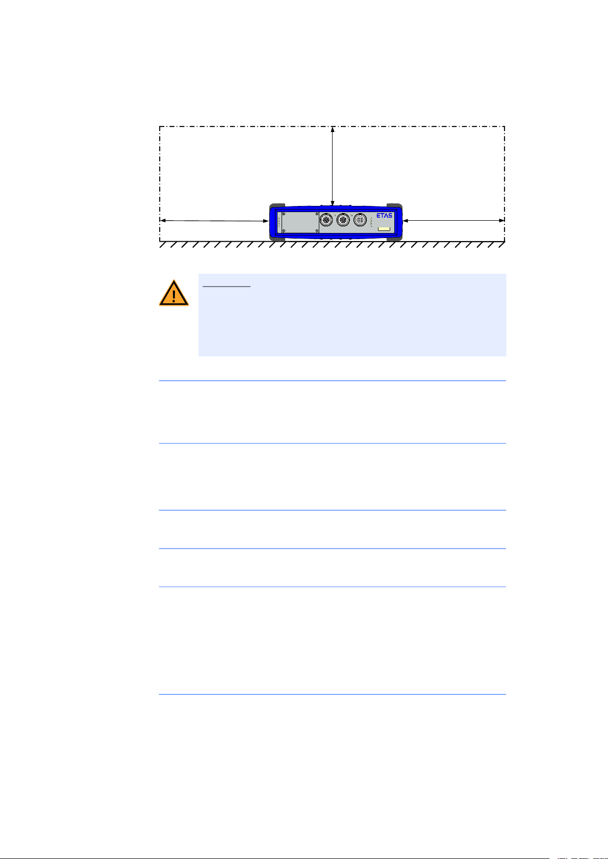
• The free space above and behind the module must be selected so that
sufficient air circulation is ensured. Adhere to the minimum distances of at
least 10 centimeters on the sides and above the module.
• Do not operate the module in completely enclosed containers.
CAUTION!
Heat concentration on the long sides of the module.
The electronics can be damaged due to overheating.
Do not cover ventilation slits when setting up, assembling or connecting with other modules. Adhere to the minimum distance at the sides.
ES920.1 - User’s Guide 11
Page 12
ETAS Basic Safety Notices
10 cm
10 cm
10 cm
CAN 1
LIN1
CAN 2
LIN 2
ETK
TT
ON
TX
ER
°C
1
2
R
H
ES910.3
A
CAUTION!
Heat concentration on the top of the module.
The electronics can be damaged due to overheating.
Do not stack several ES910.3-A modules on top of each other.
When stacking the ES910.3-A with other ETAS modules, it always has
to be on top.
Assembling (interconnecting) the modules
• Prior to assembling (interconnecting) or separating a module stack, the
modules must be disconnected from the supply voltage or they have to be
in the standby operating mode.
Transport
• Stack and connect the modules only at the location of the startup!
• Do not transport the modules at the cable of the module or any other
cables.
Maintenance
The product is maintenance-free.
Repair
If an ETAS hardware product should require a repair, return the product to ETAS.
Cleaning the module housing
• Use a dry or lightly moistened, soft, lint-free cloth for cleaning the module
housing.
• Do not user any sprays, solvents or abrasive cleaners which could damage
the housing.
• Ensure that no moisture enters the housing. Never spray cleaning agents
directly onto the module.
Ambient conditions
The housing and the connectors of the module as well as the plug connectors of
the cables meet the degree of protection IP30.
ES920.1 - User’s Guide 12
Page 13
ETAS Basic Safety Notices
Opening the module
CAUTION!
Damage to the module and loss of properties based on IP30!
Do not open or change the module housing!
Work on the module housing may only be performed by ETAS.
Potential equalization
CAUTION!
Potential equalization in the vehicle is possible via the shield of
the connecting cables of the modules!
Install the modules only at locations with the same electrical potential
or isolate the modules from the installation location.
Cabling
For detailed information about cabling, see the User's Guide of the module.
ES920.1 - User’s Guide 13
Page 14

ETAS Hardware Description
3 Hardware Description
This chapter provides an overview of FlexRay and the ES920.1 module and provides you with information on its properties, connectors and the LED.
3.1 Overview
3.1.1 FlexRay
The complexity of vehicle electronics is permanently on the increase due to the
increasing number, growing function scope and the networking of electronic
ECUs in vehicles. Error-free functioning of the systems is essential for safety
applications such as X-by-Wire (e.g. for the brake system or steering). This
requires, for example, reliable and real-time-capable data transfer between the
electrical and mechatronic components.
The new powerful FlexRay bus system fulfils these demands. It has a range of
innovative functional and safety features with which system safety in vehicles can
be improved. The FlexRay bus system enables data rates of up to 10 MBit/s in a
topology of point-to-point connections, active stars and mixed systems. Typical
of this topology are, for example, ideal bus terminations and thus minimized
reflections, defined electrical behavior, flexible expandability, error delimitation
on affected branches and optimized EMC behavior.
The importance of the standardized FlexRay bus system is permantenly on the
increase in development projects in the automotive industry. Due to redundant
data transfer, FlexRay can also be used in safety-critical applications and the
deterministic structure enables messages to be transferred reliably.
The signals to be monitored can be selected from the set of all signals available
in the connected cluster. To obtain the corresponding information, the FIBEX file
is imported to INTECRIO. INTECRIO then uses the FIBEX file to configure the
FlexRay hardware.
ES920.1 - User’s Guide 14
Page 15

ETAS Hardware Description
3.1.2 Definitions
FlexRay
FlexRay is a scalable and fault-tolerant communication system for deterministic data exchange at high transfer rates. Using the time multiplex
procedure enables the creation of distributed systems with a highly modular structure and high safety demands. The high bandwidth of 10 MBaud
on two channels plays its part in overcoming high network loads caused
by the increasing number of innovative electronic systems in modern vehicles.
The specifications of this communication system are issued by the FlexRay
Consortium, a committee which is supported by a large number of vehicle
manufacturers and suppliers worldwide.
FIBEX
FIBEX (Field Bus Exchange) is an XML scheme based exchange format
used to describe the entire communication network in the vehicle. FIBEX
is designed for various types of network (CAN, LIN, MOST, FlexRay) and
includes information on bus architecture, signals, properties of the network nodes etc.
INTECRIO uses FIBEX files to coordinate software tools and ECUs and the
communication scheme dictated by the FlexRay cluster, i.e. the FIBEX file
defines, amongst other things, the signals. It also contains data to configure the hardware interface. The FIBEX files have to be made available by
the vehicle manufacturer.
More information on the FIBEX standard can be obtained from
http://www.asam.net
.
ES920.1 - User’s Guide 15
Page 16

ETAS Hardware Description
3.2 ES920.1
3.2.1 Features
The ES920.1 FlexRay Module, when accommodated in the extension slot of the
ES910 Rapid Prototyping Module, enables rapid prototyping applications at FlexRay channels.
Note
The ES920.1 FlexRay Module can be operated in the extension slot of the
ES910.2 and the ES910.3-A.
Together with the ES910, the ES920.1 module is part of a highly efficient, compact development and experimental platform with high computing and simulation performance due to the use of a close-to-target, fast floating-point
processor. The AUTOSAR-compatible RTA-OSEK operating system of the ES910
guarantees simple transition from the finished function prototype to ECU software development.
The ES920.1, equipped with the Bosch E-RAY IP, provides a FlexRay node with
the channels A and B which can send and receive FlexRay frames. Interrupts can
be triggered at cycle, segment and slot level.
To optimize system performance, a preprocessor handles the FlexRay communication paths independently from the simulation controller of the ES910.
Together with the ES920.1, the ES910 is hardware optimized for rapid prototyping applications used to develop FlexRay ECUs.
The ES920.1 is configured entirely in INTECRIO.
Overview of the Major Features of the ES920.1:
• One FlexRay node with two FlexRay channels which can be used redundantly
– Channels galvanically isolated from each other, from the device
ground and from the supply voltage
– “Wake Up” via FlexRay
• Efficient connection of the ES920.1 FlexRay port to the ES910 simulation
controller
• Use of the BOSCH E-Ray IP Module as a FlexRay Communication Controller, compatible with the FlexRay Protocol Specification V2.1
• Support of future FlexRay versions with firmware update
• Configuration possibilities in the calibration software:
– Data rates of up to 10 MBit/s
– Max. 128 frames
– 8 kByte message RAM, for example
to save 128 frames with max. 48 byte payload or
to save 30 frames with max. 254 byte payload
– Slot counter filter, cycle counter filter and channel filter
– Network management support
ES920.1 - User’s Guide 16
Page 17

ETAS Hardware Description
• After integration into the ES910, the ES920.1 is a module suitable for use
in automotive applications which is perfect for use in the development
environment and in the vehicle on test drives.
– Not sensitive to extreme environmental conditions (temperature, EMC)
– High mechanical stability and durability
• Part of the ETAS Tool Suite
– Rapid prototyping of control functions with MATLAB®/Simulink®,
ASCET-MD as well as C by integrating into INTECRIO
– INTECRIO supports:
FIBEX import to configure the FlexRay node,
The simple allocation of the signals required for control and diagnostic
functions to the FlexRay frames,
Static and dynamic FlexRay segments and
Different interrupt levels, based on frame, segment or slot
– Supported by INCA/INCA-EIP, INTECRIO, ASCET-RP, HSP
For the complete technical data of the ES920.1, refer to the chapter "Technical
Data" on page 31.
ES920.1 - User’s Guide 17
Page 18
ETAS Hardware Description
FLX1 FLX2
ES920.1
T
3.2.2 View of the Module
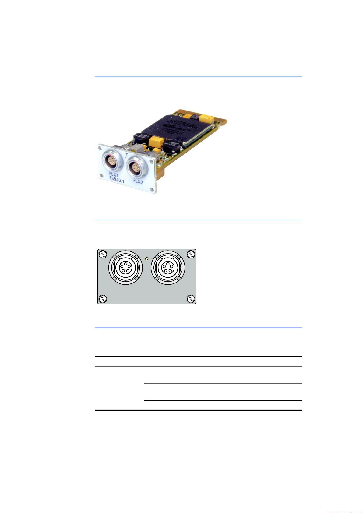
The following figure shows the ES920.1 FlexRay module with the position of the
ports and the LED.
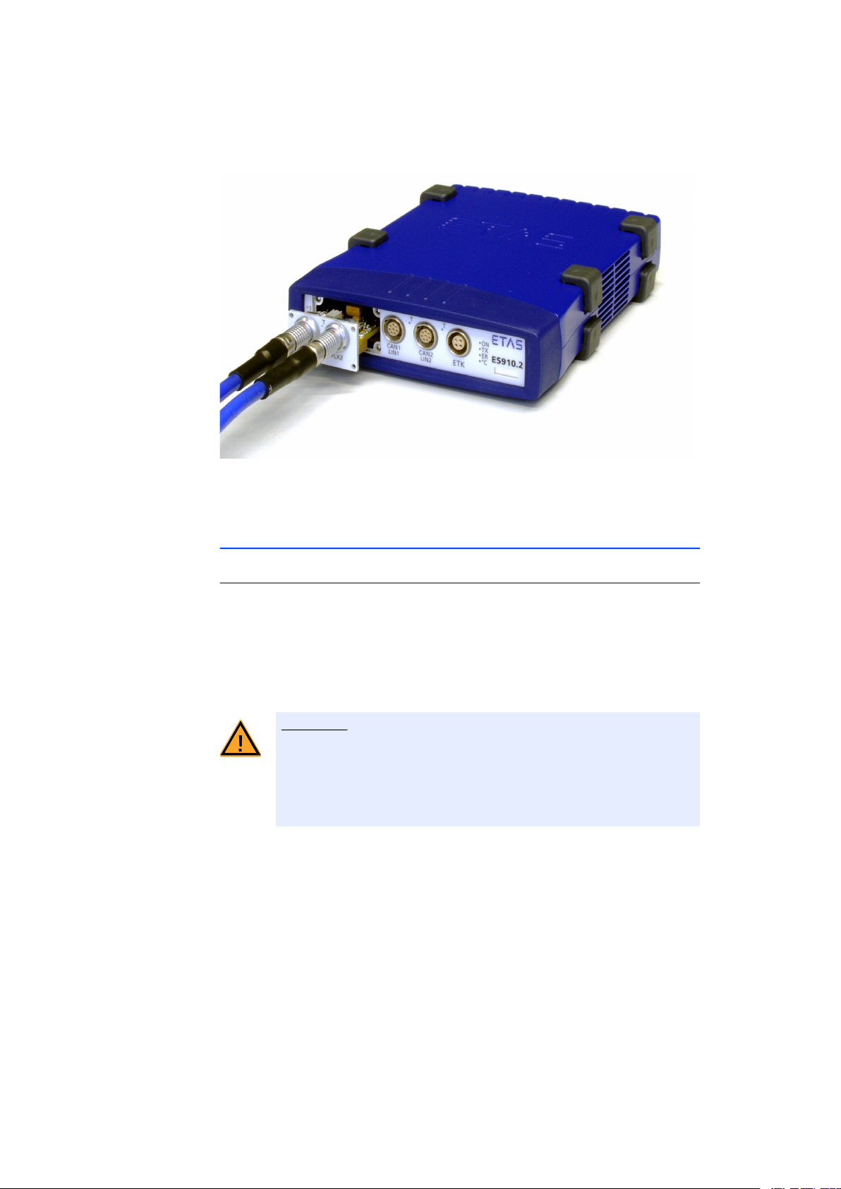
Fig. 3-1 ES920.1 Module
3.2.3 Ports
The FlexRay ports FLX1 for channel A and FLX2 for channel B are on the front of
the ES920.1.
Fig. 3-2 ES920.1Ports
3.2.4 LEDs
The ES920.1 has one LED, T, which displays the functional state of the FlexRay
node. When the ES910 is powered on, the following functional states are displayed:
LED Display Functional State
T Yellow FlexRay node active, synchronized, ready
to exchange data
Yellow, flashing FlexRay node active, waiting for synchro-
nization
Off FlexRay node inactive
ES920.1 - User’s Guide 18
Page 19
ETAS Functional Description
6 mm
FL X 1
FL X 2
Fl e x Ra y
Controller
Fl ex Ray
Tranceiver
4 Functional Description
This chapter describes the block diagram, bus termination, the “Wake Up” and
“Sleep” functions and also provides tips on the firmware update.
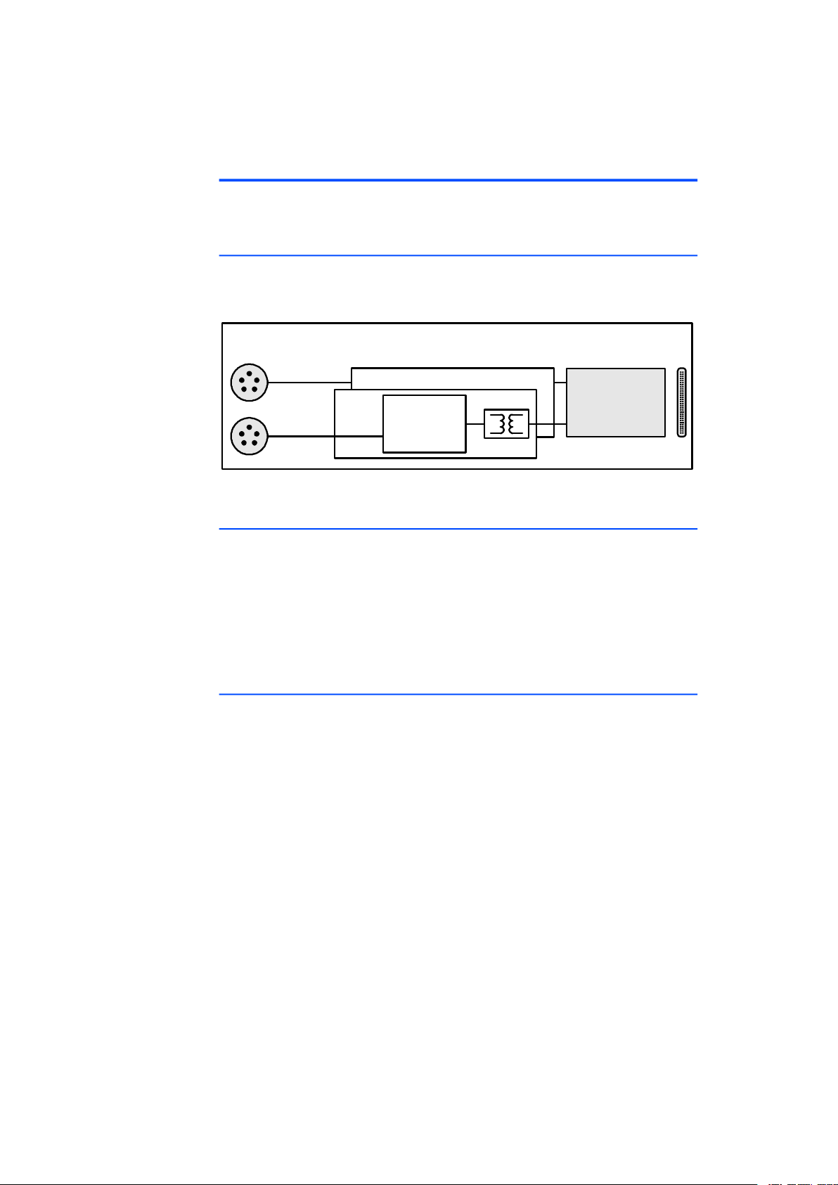
4.1 Block Diagram
The ES910 has a slot for extension modules (extension slot). This slot can, for
example, accommodate the ES920.1 FlexRay Module.
Fig. 4-1 Block Diagram of the ES920.1
4.2 Bus Termination Resistor
The FlexRay specification makes it possible to create different bus topologies,
such as a passive bus, passive star or active star.
Each of the topologies requires the relevant bus termination. The FlexRay termination designated by the ETAS FlexRay specification is 100 Ohm. To support the
creation of a rapid prototyping environment in FlexRay networks, ETAS provides
FlexRay cables with corresponding FlexRay terminations. The termination has to
be connected to the cable or to the connector.
4.3 “Wake Up” and “Sleep” Functions
The ES920.1 module supplements the “Wake Up” and “Sleep” functions of the
ES910 module with further control possibilities. The ES920.1 can control the toggling of the overall system ES910/ ES920.1 in the vehicle between on and
standby.
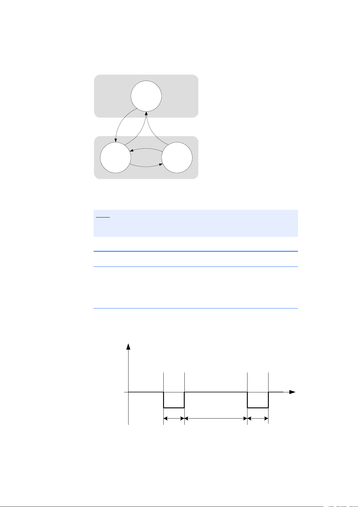
The overall system ES910/ ES920.1 can effectively be in three different states:
Off, Standby and On.
ES920.1 - User’s Guide 19
Page 20
ETAS Functional Description
ON
OFF
STANDBY
Sleep
Wake-Up
Power Connect Power Disconnect
Differential
Bus
Volt age
Idl e
t
1
t
0
t
0
DATA_0
DATA_1
DATA_0
DATA_0
DATA_1
Fig. 4-2 Operating Modes
For more detailed information on the operating modes refer to the ES910 manual.
Note
The ON/AUTO switch of the ES910 must be switched to AUTO for this function to be able to be used.
4.3.1 “Wake Up” Function
“Wake Up” Conditions
There are two different “Wake Up” conditions in the system:
• when FlexRay traffic is detected or
• when the FlexRay “Wake Up” pattern is detected.
Definition of the FlexRay “Wake Up” Pattern.
If the ES920.1 detects the “Wake Up” pattern defined in Fig. 4-3 on page 20 ,
the ES910/ ES920.1 system changes from “Standby” to “On”.
Fig. 4-3 Definition of the “Wake Up Pattern”
ES920.1 - User’s Guide 20
Page 21

ETAS Functional Description
Level Zeit Min Max
DATA_0 t
DATA_1 or Idle t
0
1
4 s 40 s
4 s 40 s
4.3.2 “Sleep” Function
The “Sleep” condition is fulfilled as soon as there is no further FlexRay traffic.
4.3.3 Configuration
The “Wake Up” and “Sleep” behavior of the ES920.1 are configured in the web
interface of the ES910 module (see section 5.5.2 on page 29).
4.4 Firmware
4.4.1 ES920.1 Firmware
Note
As delivered, the ES910 module contains no firmware to support the modules
mountable in the extension slot.
The required firmware will be loaded additionally when the extension module is
plugged in and the ES910 firmware is updated by the HSP service software. This
firmware update is esssential in following cases:
• after the first-time installation of an extension module and
• after every module type replacement in the extension slot (e.g. ES920
replaces the ES921).
If immediate successively different examplares of the same module type (e.g.
ES920) are used in the same ES910 module no additional firmware update is
necessary.
4.4.2 Firmware Update
The firmware of the ES920.1 can be updated by the user so that future versions
of the module can also be implemented. The firmware update is executed on the
connected PC using the HSP service software.
ES920.1 - User’s Guide 21
Page 22
ETAS Getting Started
5 Getting Started
The “Getting Started” chapter contains a description of how to install the
ES920.1 in and remove it from the ES910 module, the applications, wiring, configuration and notes on troubleshooting for the ES920.1.
5.1 Assembly
The extension slot on the front of the ES910 has a removable front panel. You
have to replace this front panel with the ES920.1 module if you want to use the
FlexRay channels.
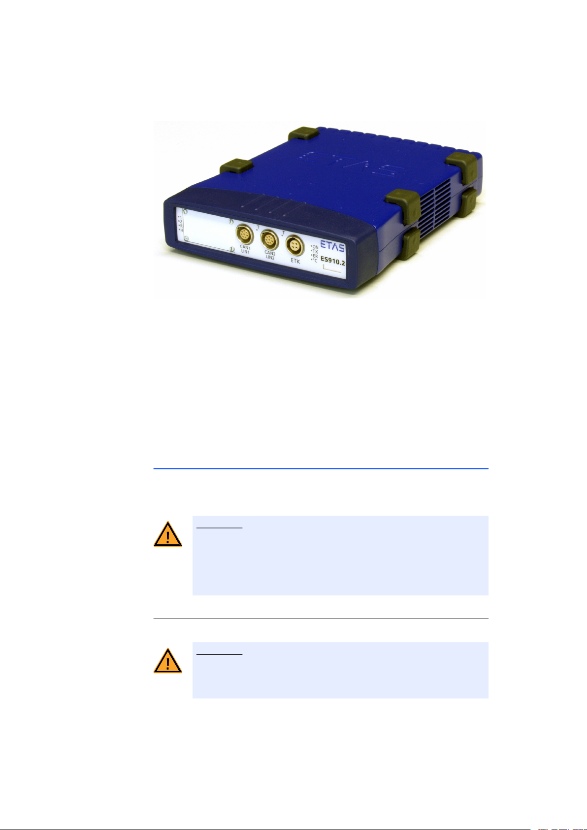
5.1.1 Removing the Front Panel of the ES910 Extension Slot
To install the ES920.1 in the ES910, you need a flat-bladed screwdriver (width of
edge 2 mm).
CAUTION!
Some components may be damaged or even destroyed by
static discharge!
Leave the module in its transport package until you want to install it.
The module should only be taken from its package and installed at a
working place that is protected against static discharge.
To remove the front panel of the ES910 extension slot:
• Switch off the power supply to the ES910 module.
• Make sure that all devices connected to the module
with cables are powered off.
• Place the ES910 on a solid surface.
CAUTION!
Damage to the ES910 possible!
The ES910 module must not be stood on its back when removing the
front panel.
The mounting screws of the extension slot must not fall into the module.
ES920.1 - User’s Guide 22
Page 23
ETAS Getting Started
• Unscrew and remove the four screws from the corners of the front panel of the extension slot.
• Keep the screws in a safe place. They are needed to
secure the ES920.1 module.
• Remove the front panel.
Four threads for the screws which will secure the
ES920.1 module become visible under the front
panel.
• Keep the front panel in a safe place. You need it if
you want to operate the ES910 without the
ES920.1.
5.1.2 Installing the ES920.1 in the ES910 Module
There are guide rails on the right and left in the extension slot of the ES910 for
accommodating the ES920.1. The mechanical connection of the modules simultaneously establishes all necessary electrical connections between the modules.
CAUTION!
Some components may be damaged or even destroyed by
static discharge!
Leave the module in its transport package until you want to install it.
The module should only be taken from its package and installed at a
working place that is protected against static discharge.
To install the ES920.1 into the ES910 module:
• Place the ES910 on a solid surface.
CAUTION!
Damage to the ES910 possible!
The ES910 module must not be stood on its back when the ES920.1
is installed in the ES910 module.
ES920.1 - User’s Guide 23
Page 24
ETAS Getting Started
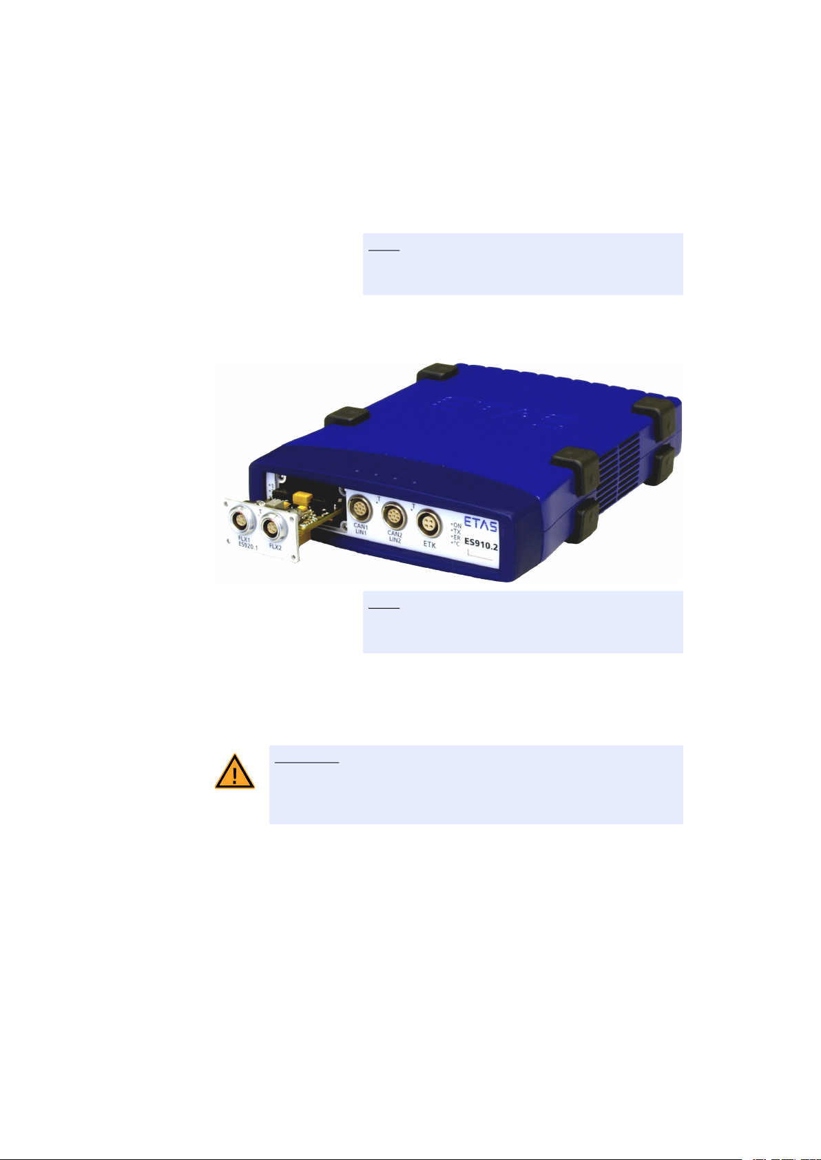
• Position the ES920.1 in front of the extension slot of
the ES910 module.
Align the back of the ES920.1 with the front of the
housing of the ES910.
Note
The labeling on the fronts of both modules must be
pointing in the same direction!
• Slide the module into the guide rails without getting it off-line.
Note
The contact spring in the extension slot of the ES910
must not be damaged when the ES920.1 is installed.
• Press on the front panel of the ES920.1 from the
front.
The connectors of the ES920.1 and the ES910 click
into place.
CAUTION!
Damage to the ES910 possible!
The mounting screws of the extension slot must not fall into the module.
• Screw the four screws with which the front panel
was attached into the front panel of the ES910
module.
• Screw the two modules together.
ES920.1 and ES910 are now mechanically connected. All necessary electrical connections
between the ES920.1 and ES910 were established
at the same time.
ES920.1 - User’s Guide 24
Page 25
ETAS Getting Started
5.2 Disassembly
5.2.1 Removing the ES920.1 from the ES910 Module
To remove the ES920.1 from the ES910, you need a flat-bladed screwdriver
(width of edge 2 mm). To make removing the device simpler, make sure you
have two CBF100-2 FlexRay cables readily available.
CAUTION!
Some components may be damaged or even destroyed by
static discharge!
Leave the module in its transport package until you want to install it.
The module should only be taken from its package and installed at a
working place that is protected against static discharge.
To remove the ES920.1 from the ES910 module:
• Switch off the power supply to the ES910 module.
• Make sure that all devices connected to the module
with cables are powered off.
• Place the ES910 on a solid surface.
CAUTION!
Damage to the ES910 possible!
The ES910 module must not be stood on its back when the ES920.1
is being removed.
The mounting screws of the extension slot must not fall into the module.
• Unscrew and remove the four screws from the corners of the front panel of the extension slot.
Keep the screws in a safe place. They are needed to
attach the front panel.
• Connect one FlexRay cable to each of the FlexRay
ports.
• Get hold of the cables as near as possible to the
module.
• Slide the ES920.1 module out of the ES910 without
getting it off-line.
ES920.1 - User’s Guide 25
Page 26
ETAS Getting Started
• Remove the two cables from the ES920.1.
• Store the ES920.1 in accordance with the ESD regulations.
5.2.2 Attaching the Front Panel of the ES910 Extension Slot
To attach the front panel of the ES910 extension slot:
• Position the front panel in front of the extension
slot of the ES910 module.
Align the back of the front panel with the front of
the housing of the ES910.
• Use the screws the ES920.1 was attached with to
screw on the front panel.
CAUTION!
Damage to the ES910 possible!
The ES910 module must not be stood on its back when the front
panel is being attached.
The mounting screws of the extension slot must not fall into the module.
• Tighten the four screws on the front panel of the
ES910 module.
The ES910 and the front panel are now mechanically connected.
ES920.1 - User’s Guide 26
Page 27
ETAS Getting Started
B
5.3 Applications
5.3.1 Function Development for FlexRay ECUs
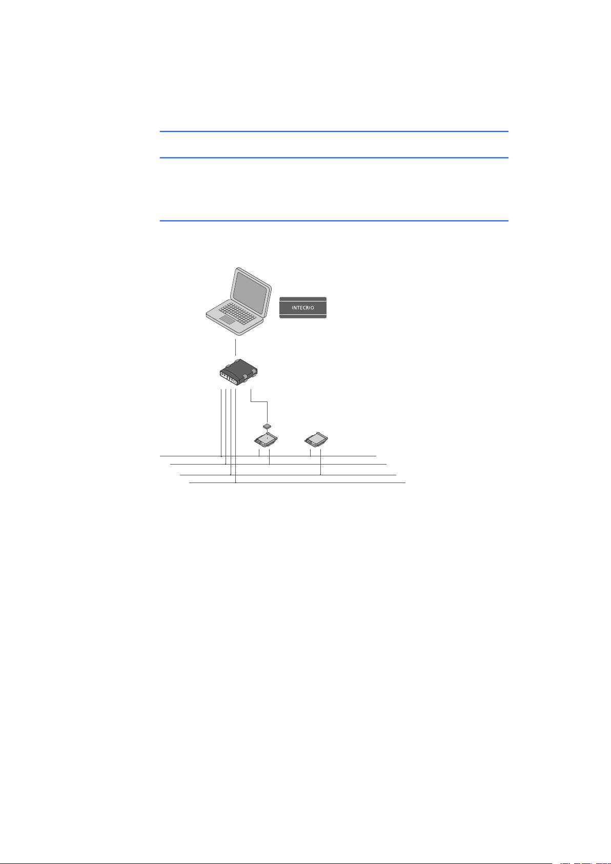
In conjunction with the ES920.1, the ES910 enables the creation of a highly efficient FlexRay node with two channels for sending and receiving FlexRay frames
(see Fig. 5-1 on page 27).
5.3.2 Gateway Function between CAN and FlexRay Buses
In conjunction with the ES920.1, the ES910 enables the creation of a gateway
between a highly efficient FlexRay node with two channels and one CAN bus.
Ethernet
ES910
ES920
ETK
ECU
ECU
FlexRay Channel A
FlexRay Channel
CAN A
CAN B
Fig. 5-1 Function Development for FlexRay ECUs with INTECRIO and the
ES910 Rapid Prototyping Module
ES920.1 - User’s Guide 27
Page 28
ETAS Getting Started
E
ES910.2
•1
•2
•R
CAN1
LIN1
CAN2
LIN2
ETK
•ON
•TX
•ER
•˚C
•
T
•
T
Power supply
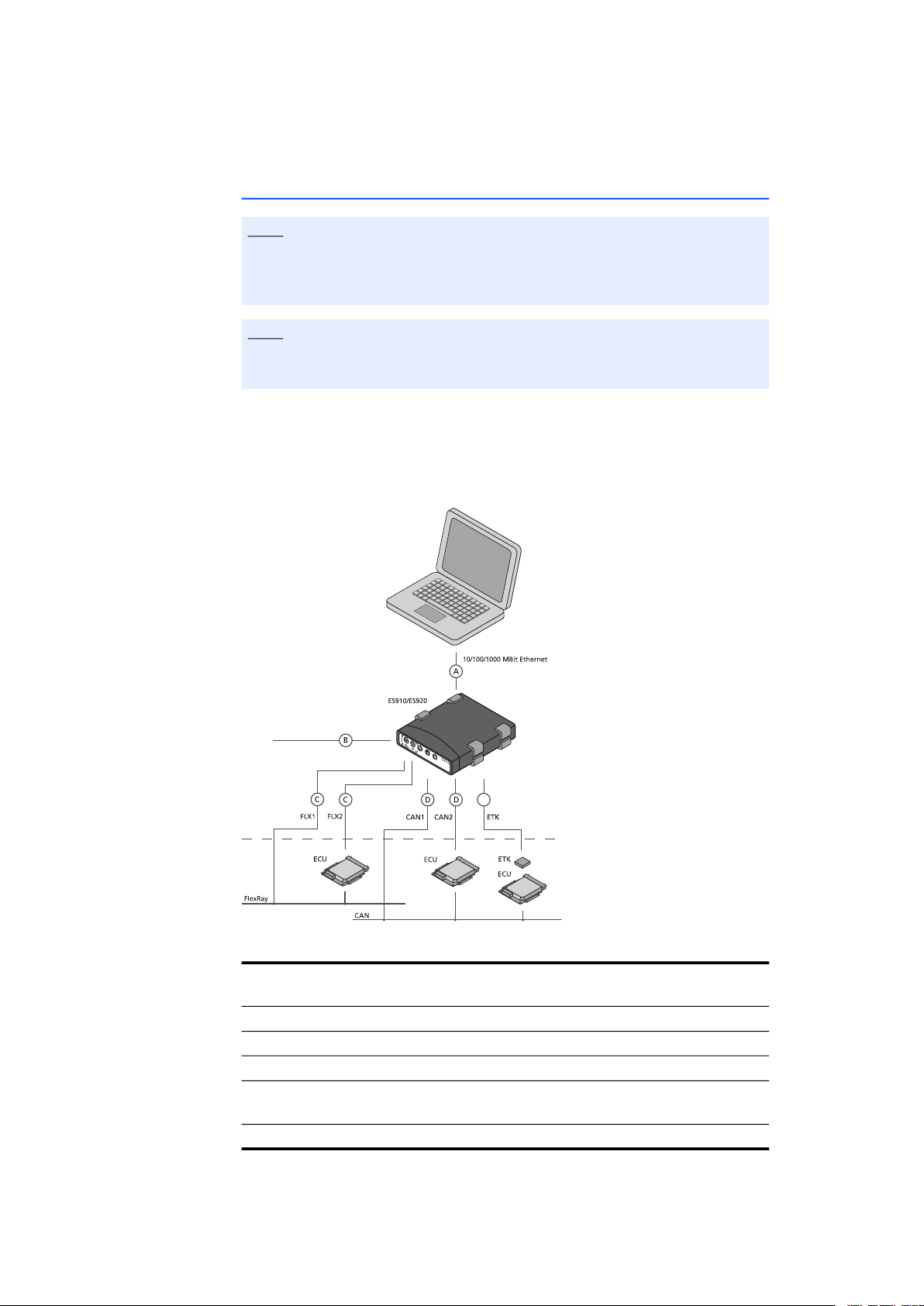
5.4 Wiring
Note
Make sure you carefully check the names of the cables used. Using the wrong
cables can keep your ES920.1 from functioning properly or damage the
ES920.1 and any devices connected to it.
Note
The ports of the ES920.1 must be wired in accordance with the FlexRay specification.
ETAS supplies special connecting cables which can be ordered separately if
required. An overview is contained in the chapter "Accessories" on page 39.
The CBF100-2 cable, a Y cable, is used to split the FlexRay bus. Termination resistors for this cable can be ordered separately.
Fig. 5-2 Wiring the ES920.1 and ES910 Modules
Cable in
Function Short Name
Fig. 5-2
A PC connecting cable CBE200
B Power supply cable CBP120, CBP1205
C FlexRay connecting cable CBF100
D CAN connecting cable K106, K107, K95, CBAC140, CBAC150,
E ETK connecting cable CBM150
CBCX130
ES920.1 - User’s Guide 28
Page 29

ETAS Getting Started
5.5 Configuring the ES920.1
The ES920.1 is configured on your PC in the application program; the “Wake
Up” function of the ES920.1 is configured in the web interface of the ES910
module.
5.5.1 Web Interface
The web interface of the ES910 consists of a home page, a page for customized
configuration of the ES920.1 for the “Wake Up” function and other pages.
5.5.2 Configuring the “Wake Up” Function of the ES920.1 Module
To launch the ES910 web interface:
• Connect the ES910 to the PC.
• Start the HSP program on the PC.
• Click Hardware Search.
• Highlight the ES910 to be configured in the
“Hardware” window.
• Right-click System Configuration.
The default web browser launches the web
interface for configuring the ES910 with the current
IP address of the module in the address field.
The home page of the ES910 web interface is
displayed.
To configure the “Wake Up” function:
• Click Config.
• Click Wake Up.
The page for configuring the “Wake Up” function
is displayed.
• Configure the interfaces of the ES920.1 for the
“Wake Up” function.
ES920.1 - User’s Guide 29
Page 30

ETAS Getting Started
5.6 Troubleshooting
Please observe the LEDs which provide information on the functions of the ports
and the ES920.1 (see the section "LEDs" on page 18) to be able to judge the
operational state of the ES920.1 as well as troubleshooting measures.
The following table lists one possible problem with a remedy.
Problem Diagnostic Questions Possible Solutions
The ES920.1 is not found
in HSP with “Search for
Hardware”.
If you have any further questions, please contact our Customer Support (see
chapter 9 on page 40).
Is the hardware connected to the PC with the
CBE100 cable?
Check that the connection is undamaged.
ES920.1 - User’s Guide 30
Page 31
ETAS Technical Data
6 Technical Data
This chapter describes general data, electrical data and the pin assignment of the
ES920.1.
6.1 General Data
6.1.1 Identifications on the Product
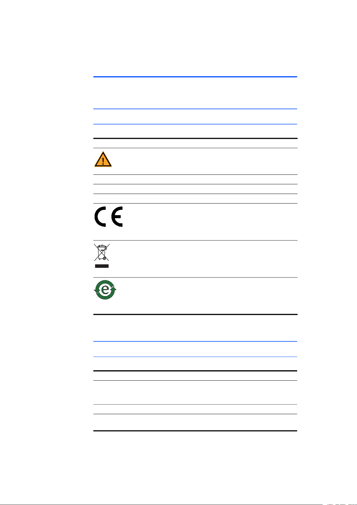
The following symbols are used for identifying the product:
Symbol Description
The User's Guide must be read prior to the startup of the
product!
SN: 1234567 Serial number (7-digit)
Vx.yz Hardware version of the product
F 00K 123 456 Order number of the product (see chapter 8.1 on page 39)
Marking for CE conformity, see chapter 6.4 on page 32
Marking for WEEE, see chapter 6.5 on page 32
Marking for China RoHS, see chapter 6.3.2 on page 32
6.2 Fulfilled Standards and Norms
CE Norms
The module adheres to the following standards and norms:
Norm Test
EN 61326 Electrical equipment for measurement,
EN 61000-6-2 Immunity (industrial environments)
EN 61000-6-4 Emission standard (industrial environ-
control and laboratory use - EMC
requirements
ments)
ES920.1 - User’s Guide 31
Page 32
ETAS Technical Data
The module is designed only for use in industrial environments in accordance
with EN 61000-6-4. When using the module outside of industrial environments
avoid possible radio disturbances by additional shielding measures!
WARNING!
This is a class A product. In a domestic environment this product may
cause radio interference in which case the user may be required to
take adequate measures.
6.3 RoHS Conformity
6.3.1 European Union
The EU Directive 2011/65/EU limits the use of certain dangerous materials for
electric and electronic devices (RoHS conformity).
ETAS confirms that the product meets this directive applicable in the European
Union.
6.3.2 China
ETAS confirms that the product meets the "China RoHS" (Management Methods for Controlling Pollution Caused by Electronic Information Products Regulation) guidelines applicable to the People's Republic of China with a China RoHS
label attached to the product or its packaging.
6.4 CE marking
With the CE mark attached to the product or its packaging, ETAS confirms that
the product corresponds to the product-specific, applicable European Directives.
The CE Declaration of Conformity for the product is available upon request.
6.5 Product return and recycling
The European Union (EU) has issued the guideline on waste electric and electronic equipment (Waste Electrical and Electronic Equipment - WEEE) in order to
ensure the institution of systems for collection, handling, and disposal of all electronic scrap.
This ensures that the devices are recycled in a resource-friendly way that does not
represent any risk to personal health and the environment.
Fig. 6-1 WEEE symbol
The WEEE symbol (see Fig. 6-1 on page 32) on the product or its packaging identifies that the product may not be disposed of together with the remaining trash.
The user is obligated to separate the waste equipment and to provide it to the
WEEE return system for reuse.
The WEEE Directive applies to all ETAS devices, but not to external cables or batteries.
ES920.1 - User’s Guide 32
Page 33

ETAS Technical Data
Additional information about the recycling program of ETAS GmbH is available
from the ETAS sales and service locations (see chapter 9 on page 40).
6.6 Use of Open Source Software
The product uses Open Source Software (OSS). This software is installed in the
product at the time of delivery and does not have to be installed or updated by
the user. Reference shall be made to the use of the software in order to fulfill
OSS licensing terms. Additional information is available in the document "OSS
Attributions List" at the ETAS website www.etas.com.
6.7 System Requirements
6.7.1 Hardware
To operate the modules, an ES910 Rapid Prototyping Module is necessary.
Note
Operating the ES920.1 is possible in the extension slot of the ES910.2 and the
ES910.3-A.
6.7.2 Software
ES920.1 mounted in the ES910.2
To configure the ES920.1 mounted in the ES910.2 and for control and data
acquisition, you need software in the following versions and higher:
Application Classifica-
FlexRay-IO RP V5.1.1 no V2.1 V6.1
FlexRay Monitoring MC V8.1.0 V6.2.1
XCP on FlexRay MC V8.1.0 V6.2.1
1)
: RP: Rapid Prototyping, MC: Measurement and Calibration
2)
: INCA V6.2.1 with Hotfix 13 and additionally INCA-ES9xx Add-On V6.2.2
and INCA-FlexRay Add-On V6.2.3 and higher
3)
: with HSP V8.1.0 and higher
tion
Support in
Application Software
HSP INCA INTECRIO ASCET-RP
1)
2)
no no
2)
no no
3)
ES920.1 - User’s Guide 33
Page 34

ETAS Technical Data
ES920.1 mounted in the ES910.3-A
To configure the ES920.1 mounted in the ES910.3-A and for control and data
acquisition, you need software in the following versions and higher:
Support in
Application Software
Application Classifica-
tion
FlexRay-IO RP V8.0.0 no V3.1.1 V6.1
FlexRay Monitoring MC V8.1.0 V6.2.1
XCP on FlexRay MC V8.1.0 V6.2.1
1)
: RP: Rapid Prototyping, MC: Measurement and Calibration
2)
: INCA V6.2.1 with Hotfix 13 and additionally INCA-ES9xx Add-On V6.2.2
HSP INCA INTECRIO ASCET-RP
1)
2)
no no
2)
no no
3)
and INCA-FlexRay Add-On V6.2.3 and higher
3)
: with HSP V8.1.0 and higher
6.7.3 ES920.1 Firmware
Note
As delivered, the ES910 module contains no firmware to support the modules
mountable in the extension slot.
The required firmware has to be loaded additionally (see chapter 4.4
on page 21).
6.7.4 Environmental Conditions
Temperature range (operation) Complies with ES910.3-A:
Temperature range (storage) -40 °C to +85 °C
Note
The module is suitable for use in interiors, in the passenger cell or in the trunk
of vehicles. The module is not suitable for installation in the engine compartment and similar environments.
6.7.5 Mechanical Data
Dimensions (H x W x D) 20 mm x 35 mm x 83 mm
Weight Approx. 50 g
-40 °C to +50 °C / -40 °F to +122 °F
-40 °F to +185 °F
ES920.1 - User’s Guide 34
Page 35

ETAS Technical Data
6.8 Electrical Data
This section contains the electrical data on the ES920.1.
6.8.1 Power Supply
Operating voltage Power supply via extension slot of the
ES910
Input voltage 3.3 V; 5 V
Power consumption (operation) 1.2 W (typ.), 1.8 W (max.)
Current consumption (standby) < 1.2 mA
6.8.2 FlexRay Module
Flexray Controller
Communication Controller Bosch E-Ray IP-Module (FPGA-based)
Number of nodes/channels 1 node with 2 channels
FlexRay Specification V2.1
FlexRay Conformance Test According to ISO 9646
Frames per communication cycle Send and/or receive max. 128 frames
Payload Max. 254 bytes
Hardware-based filtering Slot counter, cycle counter and channel
Physical Layer
Bus driver Philips TJA 1080 (per channel)
Galvanic Isolation
Galvanic isolation Both channels are galvanically isolated
from each other and from other parts
of the circuit
Miscellaneous
Functions Wake Up, Sleep
LED Status display of FlexRay bus
ES920.1 - User’s Guide 35
Page 36

ETAS Technical Data
1
2
5
3
4
6.9 Pin Assignment
Note
All ports are shown with a view of the ports of the ES920.1.
All shields are at case potential.
Fig. 6-2 FlexRay Ports (FLX1, FLX2)
Pin Signal Meaning
1 FlexRay GND Ground (FlexRay)
2 FlexRay Low
3 FlexRay Low Optional for termination resistor
4 FlexRay High
5 FlexRay High Optional for termination resistor
1)
1)
1)
Specifications of the FlexRay interface: www.flexray.com
ES920.1 - User’s Guide 36
Page 37
ETAS Cables and Accessories
CBF100.2-2 F 00K 104 180
FlexRay
0000
7 Cables and Accessories
Note
Only use ETAS cables at the ports of the ES920.1. The maximum admissible
cable lengths must be adhered to.
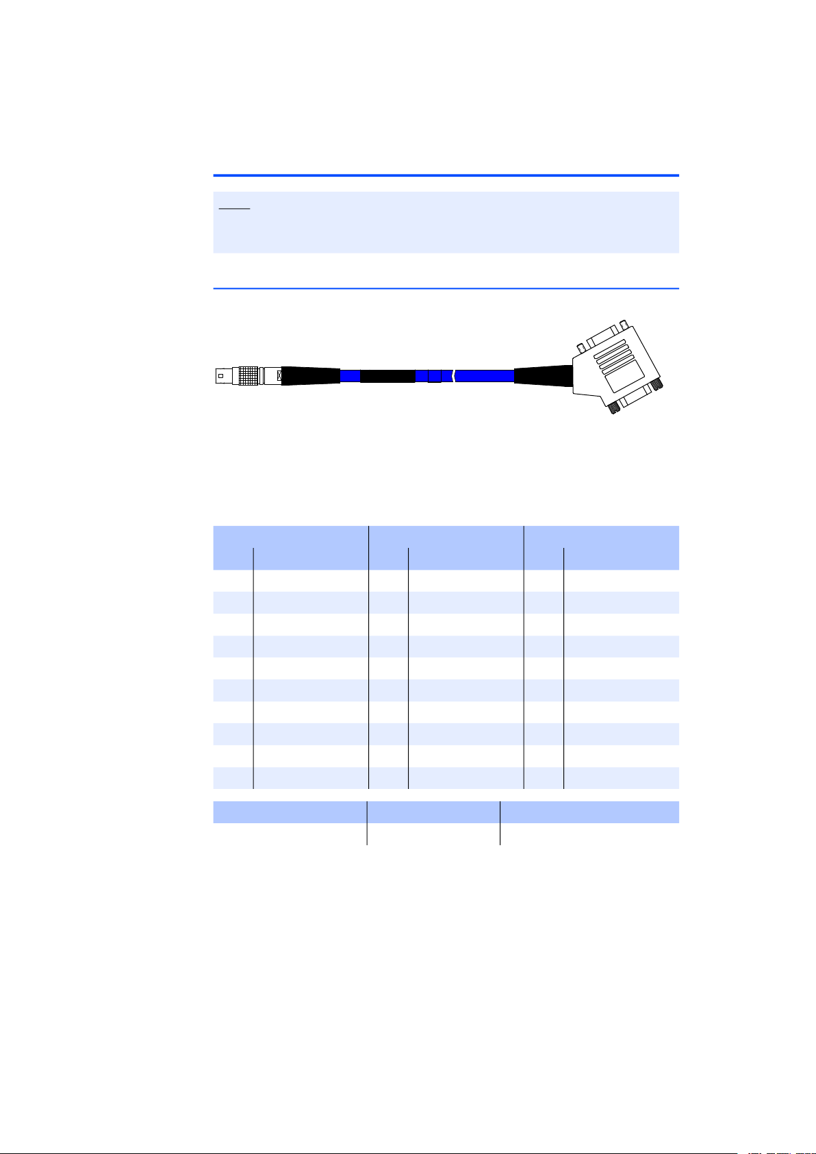
7.1 FlexRay Interface Cable
Side A Side B
Side C
Fig. 7-1 CBF100-2 Cable
Side A Side B Side C
Pin Signal Pin Signal Pin Signal
1 FlexRay GND 1 n.c. 1 n.c.
2 FlexRay Low 2 FlexRay Low 2 FlexRay Low
3 FlexRay Low 3 FlexRay GND 3 FlexRay GND
4 FlexRay High 4 n.c. 4 n.c.
5 FlexRay High 5 n.c. 5 n.c.
6 n.c. 6 n.c.
7 FlexRay High 7 FlexRay High
8 n.c. 8 n.c.
9 n.c. 9 n.c.
S1 Shield S1 Shield S1 Shield
Product Length Order Number
CBF100-2 2 m F 00K 104 180
ES920.1 - User’s Guide 37
Page 38
ETAS Cables and Accessories
5
4
3
2
1
6
7
8
9
5
4
3
2
1
9
8
7
6
100R0 / 1%
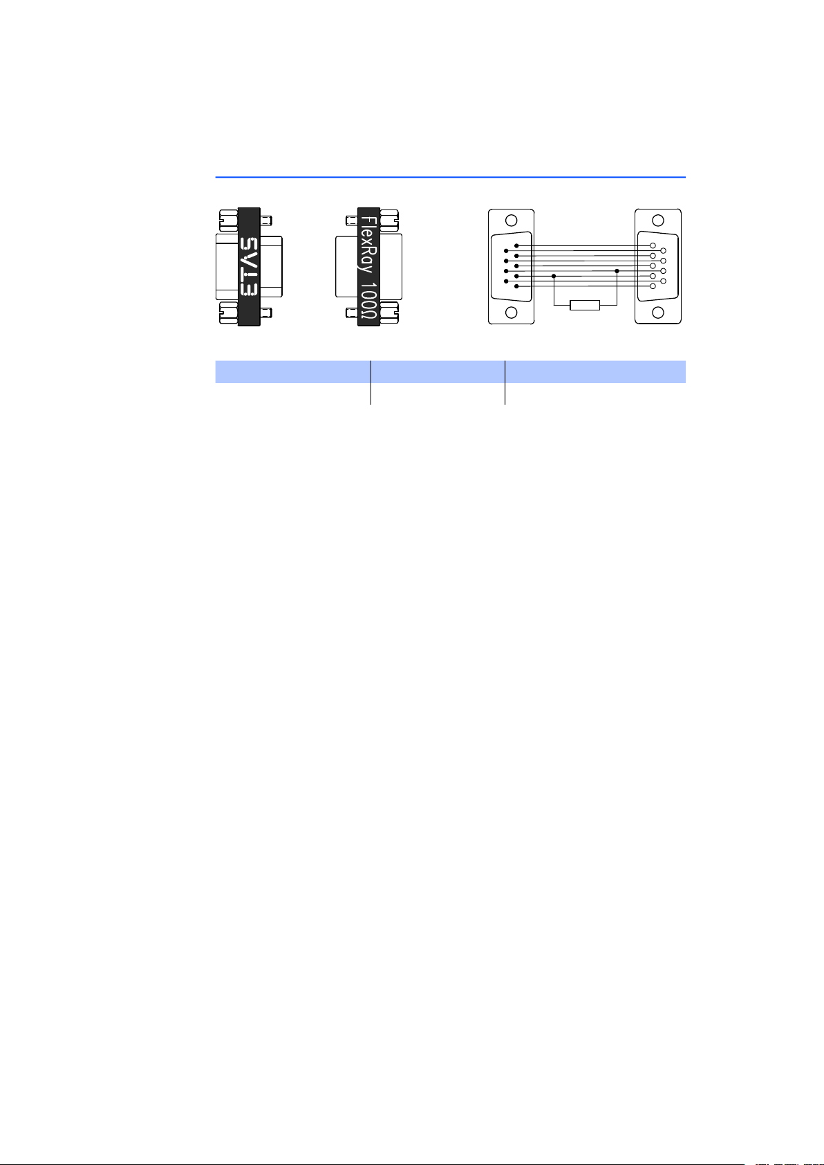
7.2 FlexRay Interface Termination Resistor
Fig. 7-2 CBFX131-0 Termination Resistor
Product Length Order Number
CBFX131.1-0 - F 00K 104 689
ES920.1 - User’s Guide 38
Page 39

ETAS Ordering Information
8 Ordering Information
8.1 ES920.1
Order Name Short Name Order Number
ES920.1 FlexRay Module (2-CH) ES920.1 F 00K 104 540
Package Contents
ES920.1 FlexRay Module (2-CH),
2 x cable CBF100-2,
2 x FlexRay termination resistor CBFX131-0,
ES900_Screws,
List "Content of this Package",
FlexRay Bosch IPCore Licence,
ES910 Safety Advice,
China-RoHS-leaflet_Compact_green_cn
8.2 Accessories
8.2.1 FlexRay Interface Cable
Order Name Short Name Order Number
FlexRay Interface Cable DSUB,
Lemo 0B FGB - 2xDSUB (5mc-9fc+9mc),
2 m
8.2.2 Termination Resistor
Order Name Short Name Order Number
FlexRay Termination Resistor 100 Ohm,
2xDSUB (9fc-9mc), 0 m
8.2.3 Spare Screws
Order Name Short Name Order Number
ES900 Spare Screws for Extension Slot ES900_Screws F 00K 105 362
CBF100-2 F 00K 104 180
CBFX131-0 F 00K 104 689
ES920.1 - User’s Guide 39
Page 40

ETAS ETAS Contact Addresses
9 ETAS Contact Addresses
ETAS HQ
ETAS GmbH
Borsigstraße 24 Phone: +49 711 3423-0
70469 Stuttgart Fax: +49 711 3423-2106
Germany WWW: www.etas.com
ETAS Subsidiaries and Technical Support
For details of your local sales office as well as your local technical support team
and product hotlines, take a look at the ETAS website:
ETAS subsidiaries WWW: www.etas.com/en/contact.php
ETAS technical support WWW: www.etas.com/en/hotlines.php
ES920.1 - User’s Guide 40
Page 41

ETAS Figures
Figures
Fig. 3-1 ES920.1 Module ......................................................................................... 18
Fig. 3-2 ES920.1Ports .............................................................................................. 18
Fig. 4-1 Block Diagram of the ES920.1 ....................................................................19
Fig. 4-2 Operating Modes........................................................................................ 20
Fig. 4-3 Definition of the “Wake Up Pattern” .......................................................... 20
Fig. 5-1 Function Development for FlexRay ECUs with INTECRIO and the ES910 Rapid
Prototyping Module.................................................................................... 27
Fig. 5-2 Wiring the ES920.1 and ES910 Modules .................................................... 28
Fig. 6-1 WEEE symbol.............................................................................................. 32
Fig. 6-2 FlexRay Ports (FLX1, FLX2)........................................................................... 36
Fig. 7-1 CBF100-2 Cable .........................................................................................37
Fig. 7-2 CBFX131-0 Termination Resistor................................................................. 38
ES920.1 - User’s Guide 41
Page 42

Figures ETAS
ES920.1 - User’s Guide42
Page 43

ETAS Index
Index
Symbols
“Sleep”
“Sleep” function
“Wake Up Pattern”
“Wake Up”
“Wake Up” conditions
“Wake Up” function
A
Accessories
Accident prevention
Ambient temperature
Applications
Attaching
Attaching the front panel
B
Block diagram
Bus termination resistor, CAN
C
Cables
CAN bus termination resistor
CBF100-2 cable
CBFX131-0 termination resistor
CE Declaration of Conformity
Configuration
19
21
20
19
20
20
39
8
34
27
26
26
19
37
FlexRay 37
19
37
21, 29
19
32
38
D
Data
electrical
mechanical
technical
Documentation
E
Electrical data
Electrical safety
ES920.1 Firmware
ETAS Contact Addresses
F
Features
Firmware
Firmware update
Flexray Controller
FlexRay interface termination resistor
FlexRay traffic 20
Function development
Functional description
G
Galvanic isolation
Gateway function
Getting started
35
34
31
8
35
9
21, 34
40
16
21
21
35
38
27
19
35
27
22
ES920.1 - User’s Guide 43
Page 44

Index ETAS
H
Hardware
system requirements
Hardware description
I
Identifying the product
Installing in the ES910
M
Mechanical data
N
Norms
31
O
Operation
Conventions
Use Case
Ordering
Ordering information
Overview
P
Physical layer
Ports
Power supply
Presentation of information
Product
Product return
39
14
18
Exclusion of liability
34
7
6
35
35
32
33
14
31
23
39
8
6
Software
system requirements
Standards
Standards and Norms
Supply voltage
System requirements
T
Technical data
Troubleshooting
U
Use, intended
V
View of the module
W
Waste Electrical and Electronic Equip-
Web interface
WEEE return system
Wiring
X
X-by-Wire
31
35
31
30
8
ment - WEEE
21
28
14
33
31
33
18
32
32
Q
Qualification, required
R
Recycling
Removal 25
Removing front panel
RoHS conformity
S
Safety at work
Safety notices
Safety precautions
Scope of supply
Simulation controller
32
China
32
European Union
8, 9
basic
8
Identification
6
7
32
8
8
22
8
ES920.1 - User’s Guide44
 Loading...