

Page 1

ES584.1
CAN FD and LIN Bus Interface USB Module
User’s Guide
Page 2

Copyright
The data in this document may not be altered or amended without special notification from ETAS GmbH. ETAS GmbH undertakes no further obligation in relation to this document. The software described in it can only be used if the
customer is in possession of a general license agreement or single license. Using
and copying is only allowed in concurrence with the specifications stipulated in
the contract.
Under no circumstances may any part of this document be copied, reproduced,
transmitted, stored in a retrieval system or translated into another language
without the express written permission of ETAS GmbH.
© Copyright 2017 ETAS GmbH, Stuttgart
The names and designations used in this document are trademarks or brands
belonging to the respective owners.
ES584.1 – User’s Guide R01 EN - 09.2017
2
Page 3

ETAS Contents
Contents
1 About this Manual . . . . . . . . . . . . . . . . . . . . . . . . . . . . . . . . . . . . . . . . . . . . . . . . . 7
1.1 Marking of Safety Notices . . . . . . . . . . . . . . . . . . . . . . . . . . . . . . . . . . . . . . . 7
1.2 Presentation of Information . . . . . . . . . . . . . . . . . . . . . . . . . . . . . . . . . . . . . 8
1.3 Scope of Supply . . . . . . . . . . . . . . . . . . . . . . . . . . . . . . . . . . . . . . . . . . . . . . 8
1.4 Additional Information . . . . . . . . . . . . . . . . . . . . . . . . . . . . . . . . . . . . . . . . . 8
2 Basic Safety Notices . . . . . . . . . . . . . . . . . . . . . . . . . . . . . . . . . . . . . . . . . . . . . . . . 9
2.1 General Safety Information . . . . . . . . . . . . . . . . . . . . . . . . . . . . . . . . . . . . . . 9
2.2 Requirements for Users and Duties for Operators . . . . . . . . . . . . . . . . . . . . . 9
2.3 Intended Use . . . . . . . . . . . . . . . . . . . . . . . . . . . . . . . . . . . . . . . . . . . . . . . . 9
3 Hardware Description . . . . . . . . . . . . . . . . . . . . . . . . . . . . . . . . . . . . . . . . . . . . . . 13
3.1 Overview . . . . . . . . . . . . . . . . . . . . . . . . . . . . . . . . . . . . . . . . . . . . . . . . . . 13
3.2 Application Areas . . . . . . . . . . . . . . . . . . . . . . . . . . . . . . . . . . . . . . . . . . . . 14
3.3 Properties . . . . . . . . . . . . . . . . . . . . . . . . . . . . . . . . . . . . . . . . . . . . . . . . . . 15
3.4 Function Groups . . . . . . . . . . . . . . . . . . . . . . . . . . . . . . . . . . . . . . . . . . . . . 16
3.5 CAN FD Interface . . . . . . . . . . . . . . . . . . . . . . . . . . . . . . . . . . . . . . . . . . . . 16
3.5.1 Operating Modes . . . . . . . . . . . . . . . . . . . . . . . . . . . . . . . . . . . . . 16
3.5.2 Time Stamp . . . . . . . . . . . . . . . . . . . . . . . . . . . . . . . . . . . . . . . . . . 16
3.5.3 Feature . . . . . . . . . . . . . . . . . . . . . . . . . . . . . . . . . . . . . . . . . . . . . 16
3.5.4 Bus Terminating Resistor . . . . . . . . . . . . . . . . . . . . . . . . . . . . . . . . 16
3.5.5 Minimum Requirements for the CAN Connection . . . . . . . . . . . . . 17
3.6 LIN Interface . . . . . . . . . . . . . . . . . . . . . . . . . . . . . . . . . . . . . . . . . . . . . . . . 18
3.6.1 Operating Modes . . . . . . . . . . . . . . . . . . . . . . . . . . . . . . . . . . . . . 18
3.6.2 Feature . . . . . . . . . . . . . . . . . . . . . . . . . . . . . . . . . . . . . . . . . . . . . 18
3.6.3 Voltage Supply on the LIN Bus . . . . . . . . . . . . . . . . . . . . . . . . . . . . 18
3.7 USB Port . . . . . . . . . . . . . . . . . . . . . . . . . . . . . . . . . . . . . . . . . . . . . . . . . . . 19
3.8 Power Supply . . . . . . . . . . . . . . . . . . . . . . . . . . . . . . . . . . . . . . . . . . . . . . . 19
3.9 Y-Cable . . . . . . . . . . . . . . . . . . . . . . . . . . . . . . . . . . . . . . . . . . . . . . . . . . . 19
ES584.1 – User’s Guide 3
Page 4

ETAS Contents
3.10 Operating State Display . . . . . . . . . . . . . . . . . . . . . . . . . . . . . . . . . . . . . . . 20
3.11 Multi-Client Support . . . . . . . . . . . . . . . . . . . . . . . . . . . . . . . . . . . . . . . . . . 21
3.12 Updating the Firmware . . . . . . . . . . . . . . . . . . . . . . . . . . . . . . . . . . . . . . . . 21
4 Commissioning . . . . . . . . . . . . . . . . . . . . . . . . . . . . . . . . . . . . . . . . . . . . . . . . . . . 23
4.1 ES584.1 USB Driver . . . . . . . . . . . . . . . . . . . . . . . . . . . . . . . . . . . . . . . . . . 23
4.2 Preparing to Install . . . . . . . . . . . . . . . . . . . . . . . . . . . . . . . . . . . . . . . . . . . 23
4.2.1 Checking the System Requirements. . . . . . . . . . . . . . . . . . . . . . . . 23
4.2.2 CD-ROM . . . . . . . . . . . . . . . . . . . . . . . . . . . . . . . . . . . . . . . . . . . . 23
4.2.3 Installation Procedure . . . . . . . . . . . . . . . . . . . . . . . . . . . . . . . . . . 24
4.3 Installing the USB Driver . . . . . . . . . . . . . . . . . . . . . . . . . . . . . . . . . . . . . . . 24
4.4 Verifying the Installation of the USB Driver . . . . . . . . . . . . . . . . . . . . . . . . . 27
4.5 Establishing the USB Connection . . . . . . . . . . . . . . . . . . . . . . . . . . . . . . . . 28
4.6 Updating the USB Driver . . . . . . . . . . . . . . . . . . . . . . . . . . . . . . . . . . . . . . . 28
4.7 Uninstalling the USB Driver . . . . . . . . . . . . . . . . . . . . . . . . . . . . . . . . . . . . . 29
4.8 J2534 Driver . . . . . . . . . . . . . . . . . . . . . . . . . . . . . . . . . . . . . . . . . . . . . . . . 30
5 Troubleshooting Problems. . . . . . . . . . . . . . . . . . . . . . . . . . . . . . . . . . . . . . . . . . . 31
5.1 Displays of the LEDs . . . . . . . . . . . . . . . . . . . . . . . . . . . . . . . . . . . . . . . . . . 31
5.2 Problems with the ES584.1 . . . . . . . . . . . . . . . . . . . . . . . . . . . . . . . . . . . . . 31
6 Technical Data . . . . . . . . . . . . . . . . . . . . . . . . . . . . . . . . . . . . . . . . . . . . . . . . . . . 33
6.1 General Data . . . . . . . . . . . . . . . . . . . . . . . . . . . . . . . . . . . . . . . . . . . . . . . 33
6.1.1 Labeling on the Product. . . . . . . . . . . . . . . . . . . . . . . . . . . . . . . . . 33
6.1.2 Standards . . . . . . . . . . . . . . . . . . . . . . . . . . . . . . . . . . . . . . . . . . . 34
6.1.3 Ambient Conditions . . . . . . . . . . . . . . . . . . . . . . . . . . . . . . . . . . . 34
6.1.4 Maintenance of the Product . . . . . . . . . . . . . . . . . . . . . . . . . . . . . 34
6.1.5 Cleaning the Product. . . . . . . . . . . . . . . . . . . . . . . . . . . . . . . . . . . 34
6.2 RoHS Conformity . . . . . . . . . . . . . . . . . . . . . . . . . . . . . . . . . . . . . . . . . . . . 35
6.2.1 European Union . . . . . . . . . . . . . . . . . . . . . . . . . . . . . . . . . . . . . . 35
6.2.2 China . . . . . . . . . . . . . . . . . . . . . . . . . . . . . . . . . . . . . . . . . . . . . . 35
6.3 CE Mark . . . . . . . . . . . . . . . . . . . . . . . . . . . . . . . . . . . . . . . . . . . . . . . . . . . 35
6.4 Returning and Recycling the Product . . . . . . . . . . . . . . . . . . . . . . . . . . . . . . 35
6.5 Open Source Software . . . . . . . . . . . . . . . . . . . . . . . . . . . . . . . . . . . . . . . . 35
6.6 Mechanical Data . . . . . . . . . . . . . . . . . . . . . . . . . . . . . . . . . . . . . . . . . . . . . 36
6.7 System Requirements . . . . . . . . . . . . . . . . . . . . . . . . . . . . . . . . . . . . . . . . . 37
6.7.1 Hardware . . . . . . . . . . . . . . . . . . . . . . . . . . . . . . . . . . . . . . . . . . . 37
6.7.2 Software . . . . . . . . . . . . . . . . . . . . . . . . . . . . . . . . . . . . . . . . . . . . 39
6.8 Electrical Data . . . . . . . . . . . . . . . . . . . . . . . . . . . . . . . . . . . . . . . . . . . . . . . 40
6.8.1 Voltage Supply . . . . . . . . . . . . . . . . . . . . . . . . . . . . . . . . . . . . . . . 40
6.8.2 CAN Interface . . . . . . . . . . . . . . . . . . . . . . . . . . . . . . . . . . . . . . . . 40
6.8.3 LIN Interface . . . . . . . . . . . . . . . . . . . . . . . . . . . . . . . . . . . . . . . . . 41
6.9 Terminal Assignment . . . . . . . . . . . . . . . . . . . . . . . . . . . . . . . . . . . . . . . . . 42
7 Cables and Accessories . . . . . . . . . . . . . . . . . . . . . . . . . . . . . . . . . . . . . . . . . . . . . 43
7.1 Cable CBCF100 . . . . . . . . . . . . . . . . . . . . . . . . . . . . . . . . . . . . . . . . . . . . . 43
7.2 CBAC180 Cable . . . . . . . . . . . . . . . . . . . . . . . . . . . . . . . . . . . . . . . . . . . . . 45
7.3 CBH500 Cable . . . . . . . . . . . . . . . . . . . . . . . . . . . . . . . . . . . . . . . . . . . . . . 46
7.4 CBCX130 Cable . . . . . . . . . . . . . . . . . . . . . . . . . . . . . . . . . . . . . . . . . . . . . 46
7.5 CBCX131.1-0 Adapter . . . . . . . . . . . . . . . . . . . . . . . . . . . . . . . . . . . . . . . . 47
ES584.1 – User’s Guide 4
Page 5

ETAS Contents
8 Order Information. . . . . . . . . . . . . . . . . . . . . . . . . . . . . . . . . . . . . . . . . . . . . . . . . 49
8.1 ES584.1 CAN FD and LIN Bus Interface USB Module . . . . . . . . . . . . . . . . . 49
8.2 Accessories . . . . . . . . . . . . . . . . . . . . . . . . . . . . . . . . . . . . . . . . . . . . . . . . . 49
9 ETAS Contact Addresses . . . . . . . . . . . . . . . . . . . . . . . . . . . . . . . . . . . . . . . . . . . . 51
Figures . . . . . . . . . . . . . . . . . . . . . . . . . . . . . . . . . . . . . . . . . . . . . . . . . . . . . . . . . 53
Index . . . . . . . . . . . . . . . . . . . . . . . . . . . . . . . . . . . . . . . . . . . . . . . . . . . . . . . . . . 55
ES584.1 – User’s Guide 5
Page 6

ETAS Contents
ES584.1 – User’s Guide 6
Page 7
ETAS About this Manual
DANGER!
WARNING!
CAUTION!
1 About this Manual
This chapter contains information about the following topics:
• "Marking of Safety Notices" on page 7,
• "Presentation of Information" on page 8,
• "Scope of Supply" on page 8,
• "Additional Information" on page 8.
1.1 Marking of Safety Notices
The safety notices contained in this manual are marked with the general danger
symbol shown below:
The safety notices shown below are used alongside this symbol. They point out
extremely important information. Please read this information carefully.
Indicates an immediate danger with a high risk of death or serious
physical injury if not avoided.
Indicates a possible danger with moderate risk of death or (serious)
physical injury if not avoided.
Indicates a hazard with low risk of minor or moderate physical injury
or damage to property if not avoided.
ES584.1 – User’s Guide 7
Page 8

ETAS About this Manual
Note
1.2 Presentation of Information
All activities to be performed by the user are presented in a"Use Case" format.
This means that the objective to be achieved is briefly defined in the heading,
and the relevant steps required for achieving this objective are then presented in
a list. The presentation looks as follows:
Definition of the objective:
Any advance information...
•Step 1
Any explanation of step 1...
•Step 2
Any explanation of step 2...
•Step 3
Any explanation of step 3...
Any concluding comments...
Typographical conventions
The following typographical conventions are used:
Bold Labels on the device
Italic Particularly important text passages
Important notes for the user are presented a
Important note for the user.
1.3 Scope of Supply
Prior to the initial commissioning of the module, please check whether the module was delivered with all required comp
on page 49).
Additional cables and adapter
available accessories and their order designation can be found in chapter "Accessories" on page 49 of this manual or in the ETAS product catalog.
1.4 Additional Information
The configuration instructions for the module under INCA can be found in the
corresponding software documentation.
s follows:
onents and cables (see chapter 8.1
s can be obtained separately from ETAS. A list of
ES584.1 – User’s Guide 8
Page 9

ETAS Basic Safety Notices
Note
2 Basic Safety Notices
This chapter contains information about the following topics:
• "General Safety In
• "Requirements for Users and Duties for Operators" on page 9,
• "Intended Use" on page 9.
formation" on page 9,
2.1 General Safety Information
Please observe the product safety information ("ETAS Safety Advice") and the
following safety instructions to avoid health hazards or damage to the device.
Read the documentation supplied with the product (Product Safety Advice and
this user manual) prior to starting up the product.
ETAS GmbH does not assume any liability for damage due to improper handling,
improper use or non-compliance with safety measures.
2.2 Requirements for Users and Duties for Operators
The product may be assembled, operated and maintained only if you have the
required qualification and experience for this product. Improper use or use by a
user without sufficient qualification can put life at risk or cause damage to health
or property.
The system integrator is respo
uct.
General safety at work
The existing regulations for safety at work and accident prevention must be followed. All applicable regulations and laws r
adhered to when using this product.
2.3 Intended Use
Application area of the product
This product was developed and approved for applications in the automotive
sector. The module is suitable for use in interiors, in the passenger compartment
or in the trunk of vehicles. The module is not suitable for installation in the
engine compartment and similar environments. For use in other application
areas, please contact your ETAS contact partner.
Requirements for the technical state of the product
The product is designed in accordance with state-of-the-art technology and recognized safety rules. The product may be opera
condition and according to the intended purpose and with regard to safety and
dangers as stated in the respective product documentation. If the product is not
used according to its intended purpose, the protection of the product may be
impaired.
nsible for the safety of systems that use the prod-
egarding operation must be strictly
ted only in a technically flawless
ES584.1 – User’s Guide 9
Page 10

ETAS Basic Safety Notices
Requirements for operation
• Use the product only according to the specifications in the corresponding
user manual. If the product is used in any other way, product safety is no
longer ensured.
• Note the requirements for the ambient conditions.
• Do not use the product in a wet or damp environment.
• Do not use the product in potentially explosive atmospheres.
Electrical safety and power supply
• Observe the regulations applicable at the operating location concerning
electrical safety, as well as the laws and regulations regarding safety at
work.
• Connect only current circuits with safety extra-low voltage in accordance
with EN 61140 (degree of protection III) to the connections of the module.
• Ensure that the connection and setting values are adhered to (see the
information in the chapter "Technical Data").
• Do not apply any voltages to the connections of the module that do not
correspond to the specifications of the respective connection.
Power supply
• The product is powered via the USB port of a PC or a drive recorder.
• The module does not require an external power supply.
• The module must be operated directly at the USB port of a PC, a drive
recorder or an active hub.
• The use of USB cables to extend the connection between module and PC
or drive recorder is not permitted.
• The module does not support USB 1.0 interfaces.
De-energizing the module
The module does not have an operating voltage switch. It can be de-energized
as follows:
• Unplug the cable from the module's signal inputs
and
– Unplug the USB connector from the PC
or
– Unplug the USB connector from the drive recorder module
or
– De-energize the drive recorder module.
ES584.1 – User’s Guide 10
Page 11

ETAS Basic Safety Notices
Approved cables
• Use exclusively ETAS cables at the module's connections.
• Adhere to the maximum permissible cable lengths.
• Do not use any damaged cables. Cables may be repaired only by ETAS.
• Never apply force to insert a plug into a socket. Ensure that there is no
contamination in and on the socket, that the plug fits the socket, and that
you correctly aligned the plugs with the socket.
Requirements for the installation location
• Position the module or the module stack on a smooth, level and solid surface.
Requirements for the ventilation
• Keep the module away from heat sources and protect it against direct
exposure to the sun.
Transport
• Do not transport the modules using the module cable or other cables.
Maintenance
The product is maintenance-free.
Repair
If an ETAS hardware product needs to be repaired, return the product to ETAS.
Cleaning the module housing
• Use a dry or slightly dampened, soft, lint-free cloth to clean the module
housing.
• Do not use any sprays, solvents or abrasive cleaners which could damage
the housing.
• Ensure that no moisture enters the housing. Never spray cleaning agents
directly onto the module.
ES584.1 – User’s Guide 11
Page 12
ETAS Basic Safety Notices
CAUTION!
CAUTION!
Opening the module
Damage to the module and loss of properties as per the protection class.
Do not open or change the module housing.
Work on the module housing may only be performed by ETAS.
Potential equalization
Potential equalization in the vehicle is possible via the shield of
the module connecting cables.
Install the modules only at locations with the same electrical potential
or isolate the modules from the installation location.
ES584.1 – User’s Guide 12
Page 13
ETAS Hardware Description
3 Hardware Description
This chapter contains information about the following topics:
• "Overview" on page 13
• "Application Areas" on page 14
• "Properties" on page 15
• "Function Groups" on page 16
• "CAN FD Interface" on page 16
• "LIN Interface" on page 18
• "USB Port" on page 19
• "Power Supply" on page 19
• "Operating State Display" on page 20
• "Multi-Client Support" on page 21
• "Updating the Firmware" on page 21.
3.1 Overview
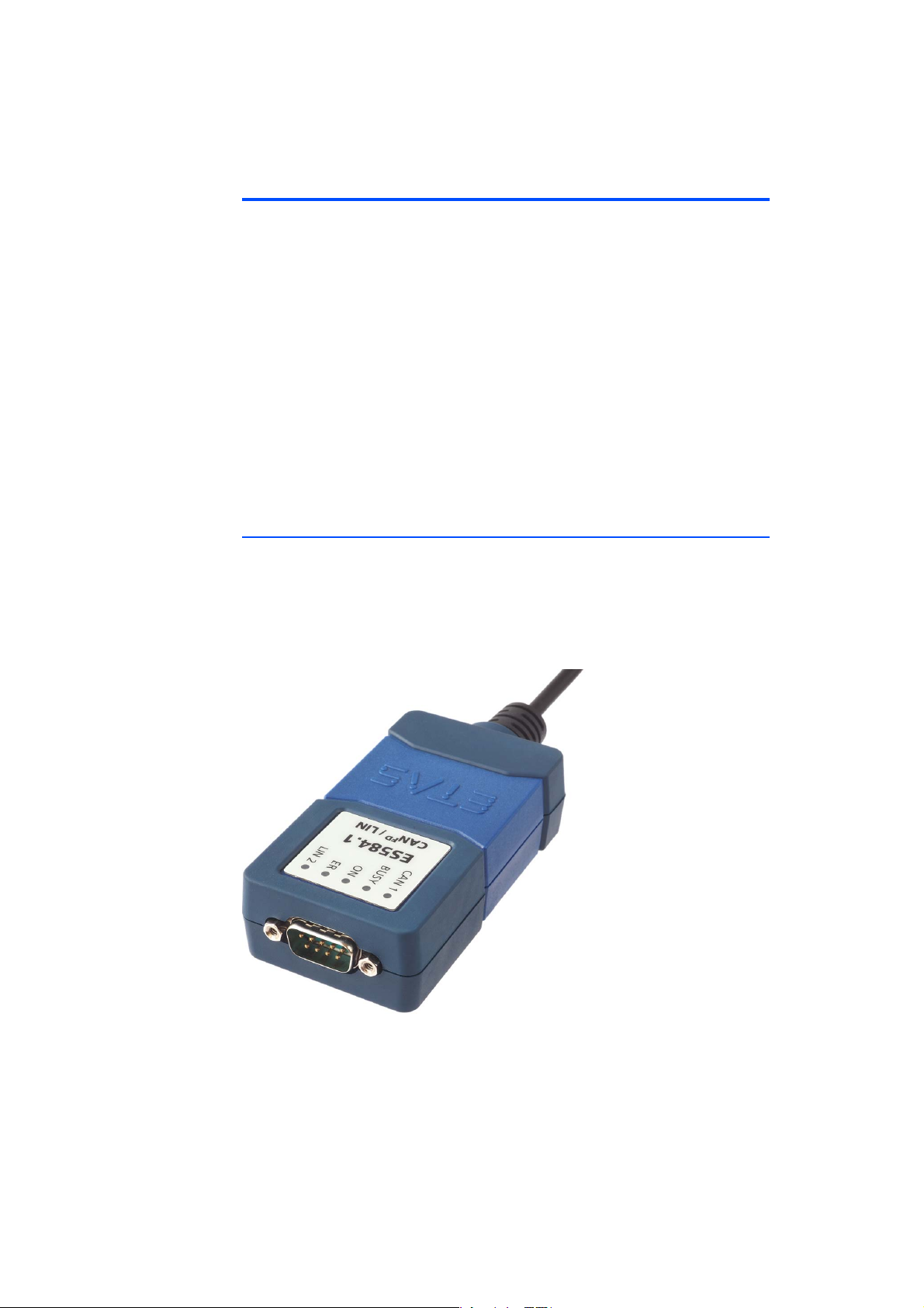
The ES584.1 CAN FD and LIN Bus Interface USB Module is part of the range of
compact ETAS bus interface modules.
It is equipped with a CAN/CAN FD interface and with a LIN interface for connection to vehicle buses or ECUs, as well as a USB po
drive recorder.
rt for connection to a PC or a
Fig. 3-1 ES584.1
The ES584.1 module supports CAN FD (CAN flexible date rate) and is suitable for
numerous applications, both in
environment.
ES584.1 – User’s Guide 13
the classic CAN environment and in the CAN FD
Page 14

ETAS Hardware Description
Together with the application software INCA and ODX-LINK from ETAS permits
the ES584.1 access to the CAN and LIN bus for measurement, calibration and
diagnostics.
The ES584.1 can be connected to a vehicle's CAN bus via the diagnostics service
interface.
When validating the vehicle diagnostics, the module can be used together with
ODX-LINK, the INCA add-on for ECU diagnostics, as an interface for OBD-onCAN, as well as to read and delete diagnostics error codes (DTCs). A separate
diagnostic service tool is not required in these cases.
The ES584.1 module offers an open SAE J2534-compliant pass-through interface for vehicle diagnostics and flash programming.
The module supports all protocols used by INCA, such as CCP, XCP, KWP-onCAN and UDS. The CCP and KWP-on-CAN (ISO 14230/ISO 15765) protocols are
only supported in classic CAN mode.
The costs for installation and configuration of the affordable module are minimal, and an external voltage supply is not required.
3.2 Application Areas
The ES584.1 can be used for the following tasks:
• Recording and capturing communication data
• Calibration of ECUs via the CAN FD bus interface
• ECU diagnostics via the CAN bus interface and J2534 pass-through interface
• Vehicle diagnostics and reprogramming via a J2534 pass-through interface using application software from third-party providers
• Flash programming of ECUs
• Connection of ETAS ES3xx modules, as well as modules from third-party
manufacturers, to the INCA PC via their CAN interface (e.g. Ipetronik or
csm modules)
• Integration of the module into the BUSMASTER open source software or
via EBI-IP into application software from third-party manufacturers
ES584.1 – User’s Guide 14
Page 15

ETAS Hardware Description
3.3 Properties
The most important properties of the ES584.1 CAN FD and LIN Bus Interface USB
Module at a glance:
• 1 CAN/CAN FD interface
– CAN operating modes
CAN high-speed
CAN FD
– CAN protocols
CAN V2.0a (standard 11-bit identifier)
CAN V2.0b (extended 29-bit identifier)
ISO-compliant CAN FD and non-ISO-compliant CAN FD
CAN channel isolated from the USB port
– Multi-client access to the same CAN channel
Max. two clients can access the device
Two clients per channel
• DSUB connector in accordance with "CAN in Automation" (CiA)
• One LIN interface
• Simple and direct connection to a USB port
• No external voltage supply necessary
• Synchronization of the measuring channels with INCA
• Fully integrated in the ETAS tool chain – supported by INCA/INCA-EIP,
INTECRIO, ASCET-RP, HSP
• Module compatible with vehicles, suitable for use in the development
environment and in the passenger compartment of motor vehicles
Complete specifications for the ES584.1 module can be found in chapter 6
on page 33.
ES584.1 – User’s Guide 15
Page 16
ETAS Hardware Description
bpRUQKN
CAN
LIN
CAN FD
Transceiver
Controller
LIN
Transceiver
LIN
Controller
Microcontroller
LED
USB Interface
Isolation
USB 2.0
CAN FD / CAN
3.4 Function Groups
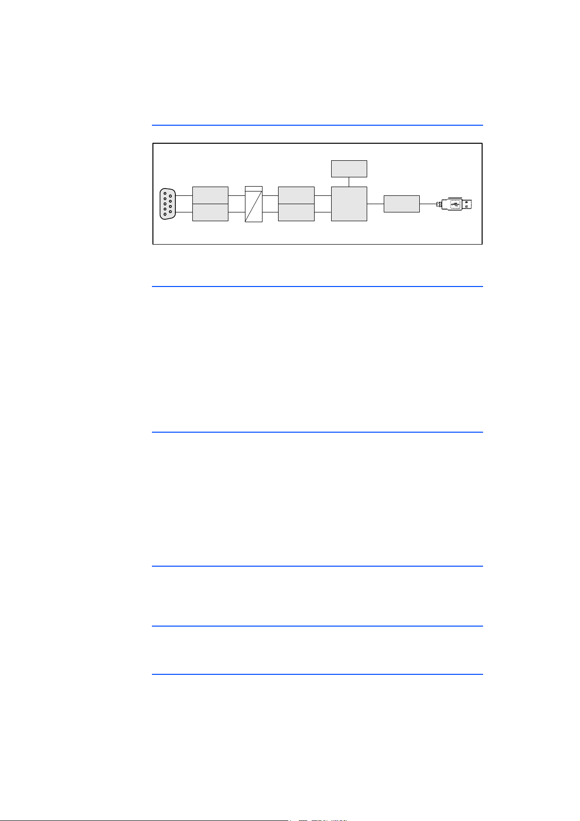
Fig. 3-2 ES584.1 block diagram
3.5 CAN FD Interface
CAN FD (CAN flexible data rate) is an improved, backward compatible CAN protocol. It differs from CAN mainly in the e
from 8 to 64 bytes, higher transmission rates of up to 8 Mbit/s and longer checksums, which increase the reliability of transmission. CAN
for a higher bandwidth for networks in the automotive industry. At the same
time, CAN FD nodes can easily be integrated into the existing CAN infrastructure.
The ES584.1 CAN FD and LIN Bus Interfac
CAN on its nine-pin DSUB socket. The CAN interface is an independent CAN
channel with its own CAN controller. It is isolated from the USB port of the
ES584.1.
xpansion of the useful data per message
FD covers the demand
e USB Module has a CAN interface
3.5.1 Operating Modes
The CAN interface can be operated in high-speed CAN operating mode or in
CAN FD operating mode (CAN flexible data rate). The ES584.1 module supports
both ISO-compliant and non-ISO-compliant CAN FD.
The CAN interface can be configured in th
ing operating modes:
• CAN
• ISO-compliant CAN FD
• Non-ISO-compliant CAN FD.
3.5.2 Time Stamp
The ES584.1 time stamps the CAN messages. The INCA application software synchronizes the measurement data recorded
from other ECUs and measuring modules with high precision.
3.5.3 Feature
The CAN applications supported by the ES584.1 are located in an overview in
chapter 6.7.2 on page 39.
3.5.4 Bus Terminating Resistor
The CAN interface requires the use of bus terminating resistors in both operating
modes.
e application software for the follow-
by the ES584.1 module with signals
ES584.1 – User’s Guide 16
Page 17

ETAS Hardware Description
Note
According to the CAN specification, one bus terminating resistor of 120 ohm is
required at each of the two open ends of the bus. It must be connected to the
cable or the plug.
ETAS offers cables and terminating resistors of 120 ohm to set up CAN networks.
Some CAN networks are already terminated (for
additional termination is required.
3.5.5 Minimum Requirements for the CAN Connection
At least the following connections are required in order to establish a connection
to the CAN network:
• Pin 2 CAN Low
• Pin 7 CAN High
• Pin 6 or Pin 3 GND (either one of the pins can be connected)
The ground connection (GND) must be identical to the ground connection of the
other CAN
nodes on the bus.
example in a vehicle), so no
ES584.1 – User’s Guide 17
Page 18
ETAS Hardware Description
LIN_GND
9
3
7
LINLIN _UBA TTDSUB-9
3.6 LIN Interface
The LIN interface is electrically isolated from the other interfaces of the module
and also protected against overload or misuse.
3.6.1 Operating Modes
The two clients of the LIN interface (see chapter "Multi-Client Support"
on page 21) can either be operated in the LIN master
LIN slave operating mode. The following configurations are possible:
• Client 1: LIN master or LIN slave and
• Client 2: LIN slave
The operating mode is selected in the
3.6.2 Feature
The LIN applications supported by the module are listed in an overview in chapter
6.7.2 on page 39.
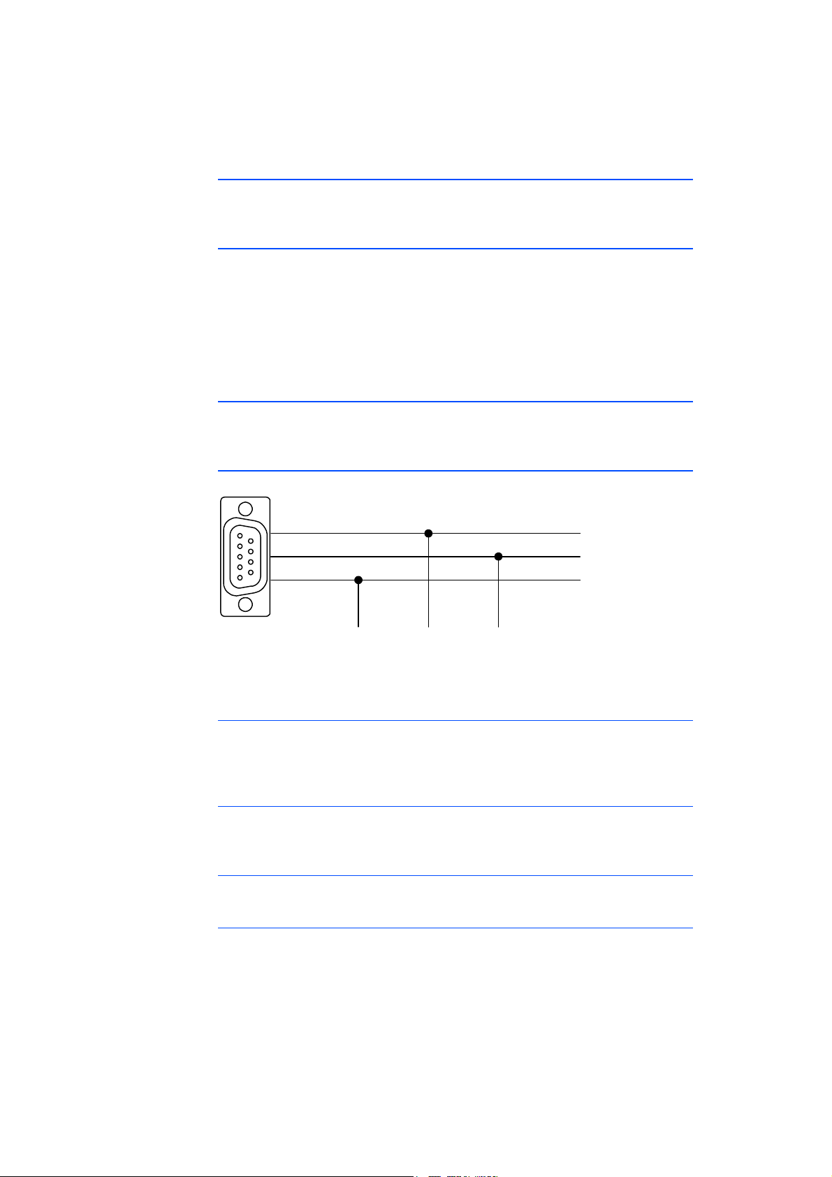
3.6.3 Voltage Supply on the LIN Bus
application software.
operating mode or in the
Fig. 3-3 Voltage supply on the LIN bus (pin assignment on the CBCF100
cable)
12 V LIN systems
In 12 V LIN systems, the LIN node of the ES584.1 module can either be supplied
externally by the LIN bus or internally by the module with the LIN reference volt-
BAT
.
age V
24 V LIN systems
In 24 V LIN systems, the LIN node of the ES584.1 module can only be supplied
externally by the LIN bus with the LIN reference voltage VBAT.
Supplying external LIN nodes
The module is not designed for the supply of external nodes on the LIN bus.
Selecting the voltage supply
An internal pull-up resistance can be switched to the LIN interface of the module
as master resistance. Switching of the master resistance of the LIN interface can
be configured in the application software.
ES584.1 – User’s Guide 18
Page 19

ETAS Hardware Description
Note
Recommendation
To maintain the reference level (and thereby identical switching thresholds) at
the individual nodes on the LIN bus, the LIN transceivers (physical layer) of all
nodes on the bus should be operated with the same voltage.
We therefore recommend
voltage that also powers the other bus participants (LIN VBAT, see Fig. 3-3
on page 18).
At the same time, this ensure compliance with sa
operating state of the LIN system (e.g. during vehicle cold starts).
If there is no access or no possibility of using the LIN V
and supply voltage, the LIN transceivers of the dedicated LIN node of the ES584.1
can be supplied by a switchable internal voltage source of the module.
This internal supply voltage is not
tor.
powering all nodes on the LIN bus with the external
fe switching thresholds in each
voltage as reference
BAT
routed outside via the CAN/LIN plug connec-
3.7 USB Port
The module is permanently connected using a cable with type A USB connector
for connection to the USB port of a PC or a drive recorder.
The module must be operated directly at the USB port of a PC, a drive recorder
or an active hub, whose USB interface meets the requirements stated in the
table in chapter
The use of USB cables to extend the connection between ES584.1 and the PC
or drive recorder is not permitted.
3.8 Power Supply
The ES584.1 module is powered via the USB 2.0 port of a PC or a drive recorder.
The module does not require an external power supply. Information on the
requirements for the PC's USB port can be found in chapter 6.7.1 on page 37.
3.9 Y-Cable
A Y-cable (CBCF100, see chapter 7.1 on page 43) allows the CAN and LIN interface of the ES584.1 module to access vehicle
6.7.1 on page 37.
buses or ECUs.
ES584.1 – User’s Guide 19
Page 20
ETAS Hardware Description
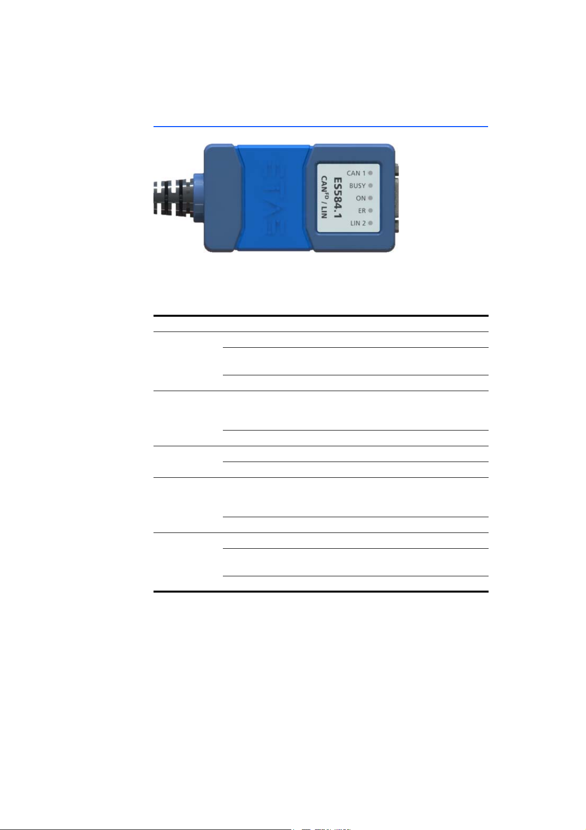
3.10 Operating State Display
Fig. 3-4 ES584.1 LEDs
The ES584.1 is equipped with five LEDs fo
state, as well as for displaying the function of the two CAN and LIN interfaces
(see Fig. 3-4 on page 20):
LED Display Description
CAN Flashing yellow Communication on the CAN interface
Off Communication on the CAN interface
rupted
Red Communication error on the CAN interface
BUSY Blue The module is currently in the boot phase or a
f
irmware update is being performed. Do not
disconnect the module from the PC!
Off Standard operation
ON Green The module is switched on
Off The module is switched off
ER Red The boot process was not successful or the
m
odule encountered a software error.
Restart the module.
Off No error
LIN Flashing yellow Communication on the LIN interface
Off Communication on the LIN interface inter-
rupted
Red Communication error on the LIN interface
r displaying the module's operating
inter-
ES584.1 – User’s Guide 20
Page 21

ETAS Hardware Description
Note
3.11 Multi-Client Support
The CAN channel and the LIN channel of the ES584.1 module can each support
two clients at the same time (application tools):
• On the CAN channel, simultaneous access is for example possible using an
application tool (e.g. IN
• On the LIN channel, simultaneous access is for example possible
application tool (e.g. INCA) and a bus analysis tool (e.g. BUSMASTER).
In total, each ES584.1 module connected to the PC can serve four (different)
clients
or application tools.
CA) and a bus analysis tool (e.g. BUSMASTER) and
using an
3.12 Updating the Firmware
The firmware of the ES584.1 can be updated by the user so that future versions
of the module can also be used. The firmware update is performed using the
ETAS service software "Hardware Service Pack" (HSP) from the connected PC.
During a firmware update, the USB connection to the PC must not be disconnected.
Other clients cannot access the module while it is being used by HSP.
ES584.1 – User’s Guide 21
Page 22

ETAS Hardware Description
ES584.1 – User’s Guide 22
Page 23

ETAS Commissioning
Note
4 Commissioning
This chapter contains information about the following topics:
• "ES584.1 USB Driver" on page 23
• "Preparing to Install" on page 23
• "Installing the USB Driver" on page 24
• "Verifying the Installation of the USB Driver" on page 27
• "Establishing the USB Connection" on page 28
• "Updating the USB Driver" on page 28
• "Uninstalling the USB Driver" on page 29
• "J2534 Driver" on page 30
• "Establishing the USB Connection" on page 28
4.1 ES584.1 USB Driver
A specific USB driver must be installed on the PC for operating the ES584.1
module.
The ES584.1 can be installed on plug & play-compatible operating systems (Windows 7, Windows 8 and Windows 10). Following installation of the driver, you
use/remove the ES584.1 module at any time.
can
4.2 Preparing to Install
4.2.1 Checking the System Requirements
Check whether your PC fulfills the system requirements (see chapter 6.7
on page 37). The installation of the USB driver on the
rights. If necessary, contact your system administrator.
4.2.2 CD-ROM
The supplied DVD includes:
• USB driver for the ES584.1 with installation wizard
• Hardware Service Pack (HSP) fo
• OSS attributions
• BUSMASTER open source software
• Documentation: ES584.1 user manual (this document)
The application for installing the USB driver is located on the DVD as an auto-
start.exe exe
Alternatively, you can install the driver
ware Service Pack" (HSP).
cutable file.
PC requires administrator
r updating the firmware
using the ETAS service software "Hard-
ES584.1 – User’s Guide 23
Page 24
ETAS Commissioning
CAUTION!
4.2.3 Installation Procedure
It is important to install the drivers first before connecting the
ES584.1 to the USB port on your computer.
Commissioning of the ES584.1 must be performed in the following sequence:
1. Installation of the USB drivers (ES584.1 not connected to the PC),
2. Establishing the USB connection,
3. Establishing the CAN connection.
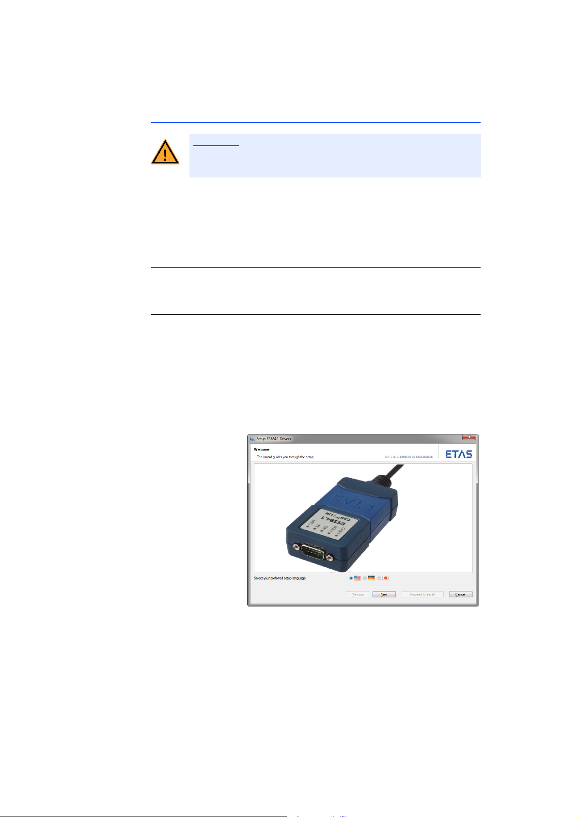
4.3 Installing the USB Driver
The procedure for installing the ES584.1 USB driver is identical, whether using
the DVD or a network drive.
Installing the USB driver for the ES584.1
• Insert the DVD into your PC.
• In the main window of the DVD, select the Drivers
op
tion.
The Dr
ivers window opens.
• Select Inst
The program for installing the
ES584.1 starts.
all ES584.1 – USB Drivers.
USB driver for the
• Select the desired language for the installation program.
• Click on Next and follow
installation program.
ES584.1 – User’s Guide 24
the instructions of the
Page 25
ETAS Commissioning
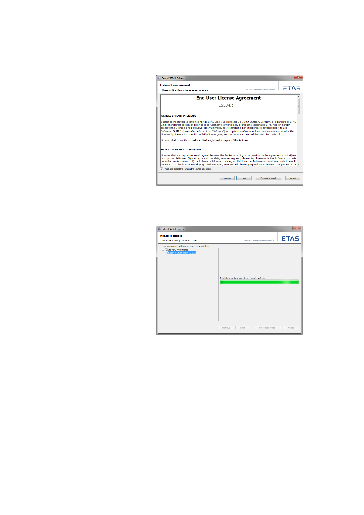
• Read and accept the end user license agreement.
• Click on Next.
The installation of the USB driver starts.
• Wait until the USB driver is installed.
ES584.1 – User’s Guide 25
Page 26
ETAS Commissioning
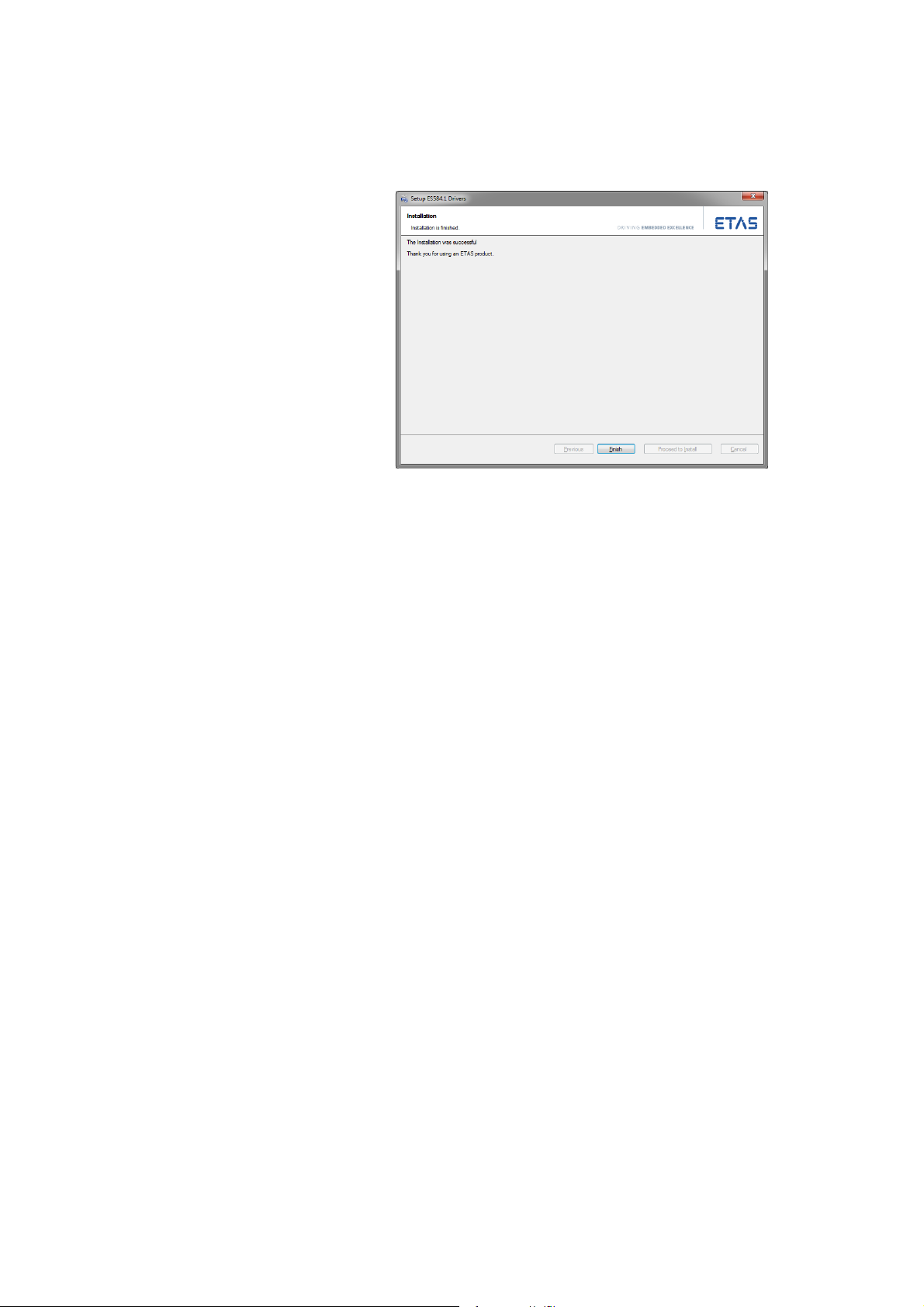
• Click on Exit.
The installation of the USB driver for the ES584.1 is
t
hen complete.
ES584.1 – User’s Guide 26
Page 27
ETAS Commissioning
4.4 Verifying the Installation of the USB Driver
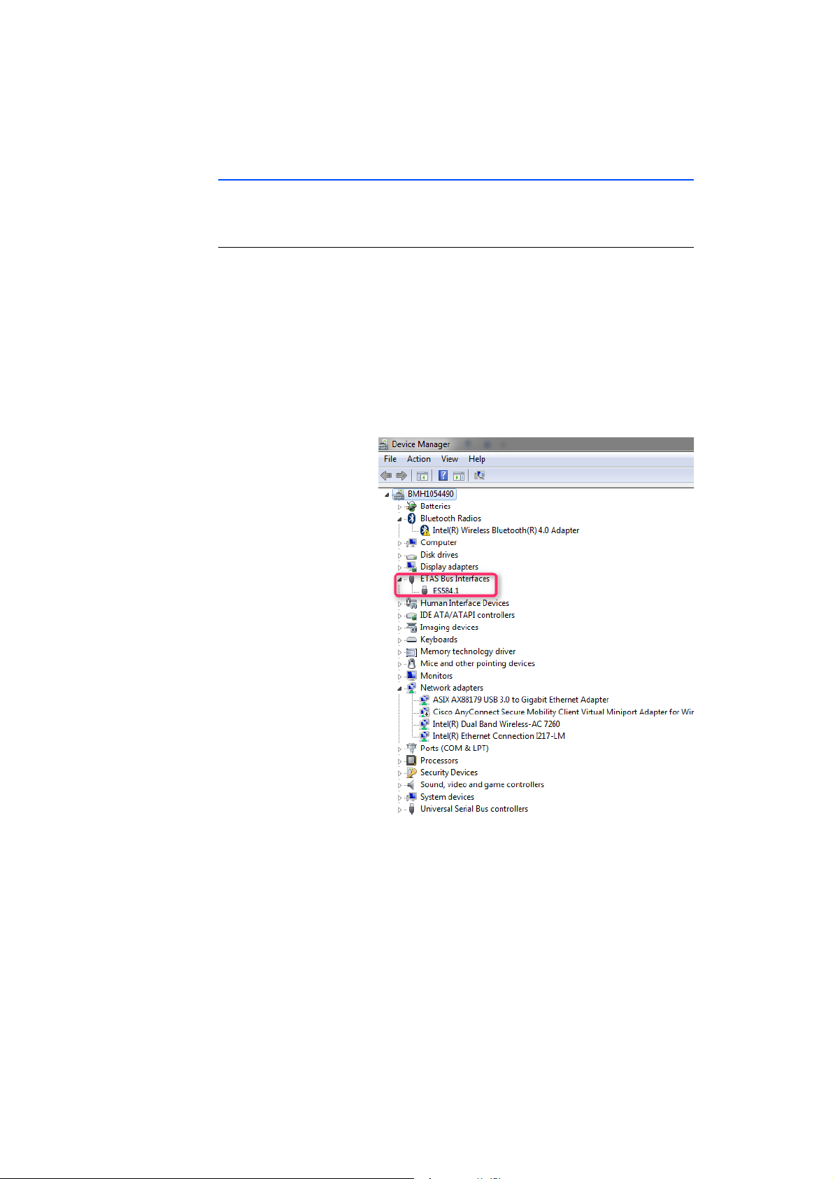
In the Windows Device Manager, you can check which hardware drivers are
installed and what their status is.
Verifying the installation of the USB driver:
• Connect the ES584.1 module to the USB port on
the PC or drive recorder.
• Select Sta
ager.
The D
• Select ETAS Bu
• Check whether the new entry ES5
for the ES584.1 module.
rt Control Panel Device Man-
evice Manager window opens.
s Interfaces.
84.1 is displayed
Fig. 4-1 Windows Device Manager
If the ES584.1 USB driver was not correctly installe
detects the module as connected, a symbol with an exclamation mark is shown
next to the device. Run the driver installation program again to resolve this issue.
ES584.1 – User’s Guide 27
d/uninstalled and Windows
Page 28
ETAS Commissioning
4.5 Establishing the USB Connection
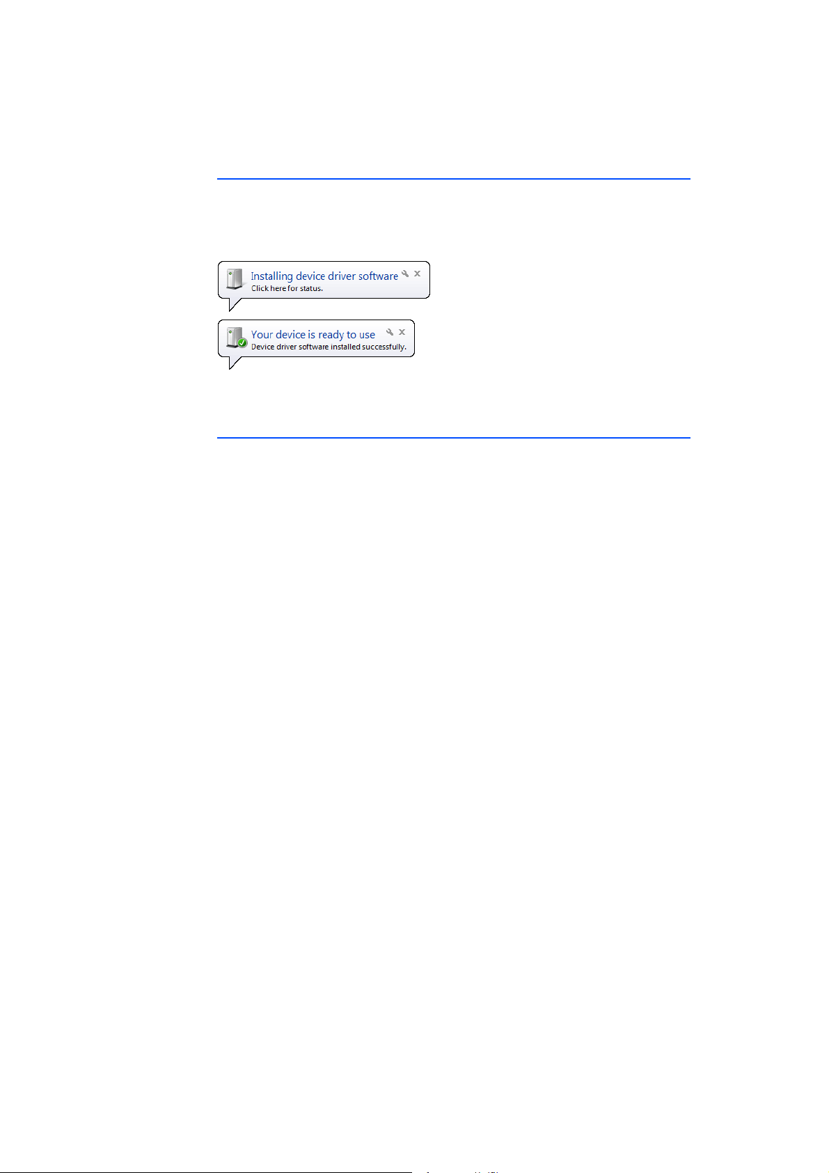
After successful driver installation, the ES584.1 can be connected to the PC. Windows should detect the device and install the accompanying driver. Windows
lays an information note in the start bar. In Fig. 4-2 on page 28, you can see
disp
an image of the information notes that appear.
Fig. 4-2 Windows information note
4.6 Updating the USB Driver
The ES584.1 update must be performed in the following sequence:
1. Ensure that the ES584.1 is disconnected from the PC.
2. Ensure that the client software applications are closed.
3. Uninstall the existing installation bef
gram.
ore launching the installation pro-
ES584.1 – User’s Guide 28
Page 29
ETAS Commissioning
4.7 Uninstalling the USB Driver
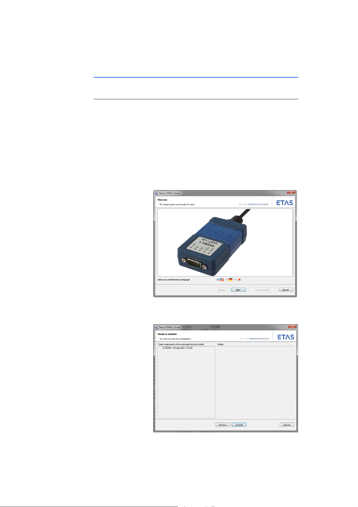
The USB driver for the ES584.1 can be uninstalled in the Windows Control Panel.
Uninstalling the USB driver for the ES584.1:
• Disconnect the ES584.1 module from the USB port
on the PC or drive recorder.
• Select Sta
Features.
The Prog
• Select the entry ES5
• Right-click and select Uninstall.
The program for uninstalling the
ES584.1 is launched.
rt Control Panel Programs and
rams and Features window appears.
84.1 Drivers.
USB driver for the
• Select the desired language for the uninstallation
program.
ES584.1 – User’s Guide 29
Page 30
ETAS Commissioning
Note
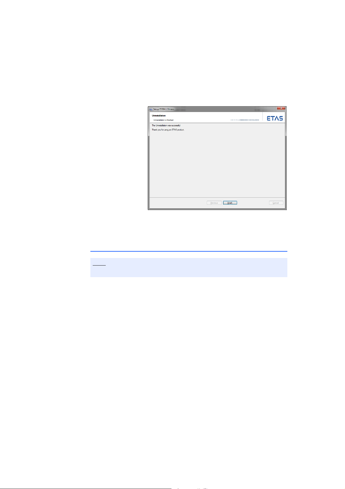
• Click on Uninstall and follow the instructions of
the uninstallation program.
The uninstallation of the USB driver starts.
• Wait until the USB driver is uninstalled.
4.8 J2534 Driver
Installation of a J2534 driver is not necessary for the ES584.1.
The packages required to support the J2534 interface are automatically installed
by the INCA application software.
• Click on Exit.
The uninstallation of the USB driver for the ES584.1
is then complete.
ES584.1 – User’s Guide 30
Page 31

ETAS Troubleshooting Problems
5 Troubleshooting Problems
This chapter provides information on what you can do when problems arise with
the ES584.1 and when general problems arise that are not specific to an individ
ual software or hardware product.
5.1 Displays of the LEDs
When assessing the operating state and rectifying faults on the ES584.1, note
the display of the LEDs which provide information about the function of the
interfaces and the ES584.1 (see chapter
3.10 on page 20).
5.2 Problems with the ES584.1
The following table lists several potential problems, as well as their corresponding solutions. If you have any further questions, please contact our technical service (see chapter 9 on page 51).
Problem Diagnostics questions Possible solution
The computer does not
install the drivers when
the module is con
nected for the first time.
The USB driver is not
being installed.
-
Has the USB driver already
been installed?
Is the USB port on the PC
defective?
Check whether the module appears in the Windows Device Manager. It
may already be installed or
was perhaps installed by
the operating system. You
can find further informa
tion on Device Manager
settings in chapter
on page 27.
Try using a different USB
port on the computer.
Restart the PC.
Ensure that you are
logged in with the neces
sary authorizations for
installing the driver
(administrator rights).
-
4.4
-
-
ES584.1 – User’s Guide 31
Page 32

ETAS Troubleshooting Problems
Problem Diagnostics questions Possible solution
The ES584.1 module is
not detected when exe
cuting the "Scan for
hardware" function.
The measurements are
not being started.
Did you install the
required version of INCA?
-
Did you install the
required version of INCA
ODX add-on?
Did you install the
required firmware on the
module?
Is the hardware connected
to the PC?
Does the INCA monitor
log ask you to perform an
update?
Does the module provide
no data?
Check whether the INCA
version installed on your
PC meets the require
ments in chapter 6.7.2
on page 39.
Check whether the INCA
ODX add-on version
installed on your PC meets
the requirements in chap
ter 6.7.2 on page 39.
Check with HSP whether
the required firmware is
installed on the module.
Check whether the
cabling is intact.
Update the firmware of
the module with HSP.
Check whether your measuring setup meets the
requirements.
Check whether the
cabling of the hardware to
the PC is correct and
intact.
Check whether the "ER"
LED is flashing: In certain
circumstances, the baud
rate may not be supported
by the module. You can
find information on the
supported baud rates in
chapter
6.8.2 on page 40.
-
-
ES584.1 – User’s Guide 32
Page 33
ETAS Technical Data
6 Technical Data
This chapter contains information about the following topics:
• "General Data" on page 33
• "RoHS Conformity" on page 35
• "CE Mark" on page 35
• "Returning and Recycling the Product" on page 35
• "Mechanical Data" on page 36
• "Open Source Software" on page 35
• "System Requirements" on page 37
• "Electrical Data" on page 40
• "Terminal Assignment" on page 42
6.1 General Data
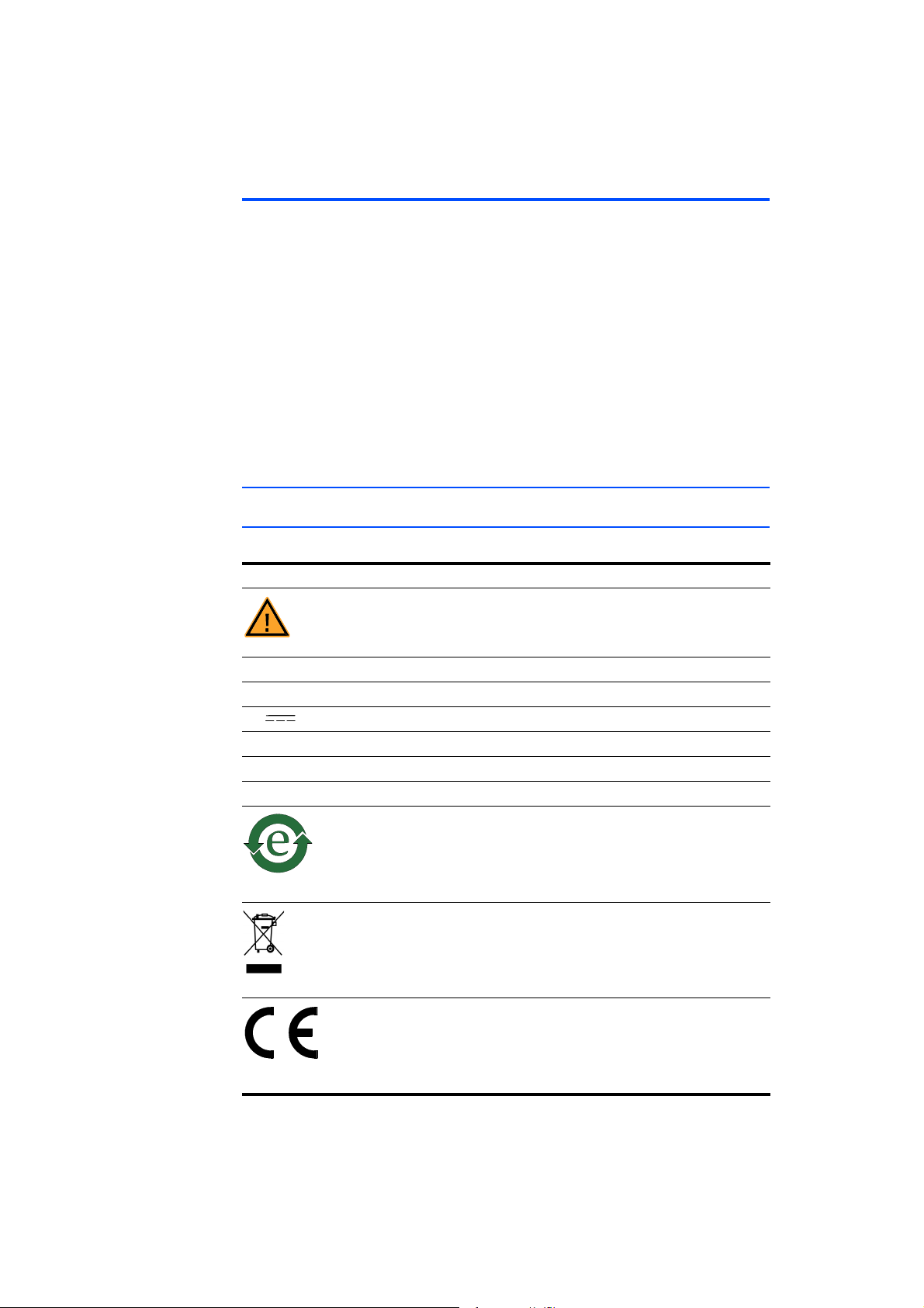
6.1.1 Labeling on the Product
The following symbols are used to label the product:
Symbol Description
Read the user manual before starting up the product.
SN: 1234567 Serial number (seven-digit)
F 00K 110 831 Order number of the product, see chapter 8 on page 49)
5 V
350 mA Current consumption, max.
ES584.1 Product designation
Operating voltage (DC)
Manufacturer's address
Marking for China RoHS, see chapter 6.2.2 on page 35
Marking for RoHS, see chapter 6.2.1 on page 35
Marking for CE conformity, see chapter 6.3 on page 35
ES584.1 – User’s Guide 33
Page 34

ETAS Technical Data
Note
6.1.2 Standards
The module complies with the following standards:
Standard Test
EN 61326-1 Electrical equipment for measurement,
EN 61010-1 Safety requirements for electrical
EN 60529 Degrees of protection provided by
EN 60068-2-32 Environmental testing
6.1.3 Ambient Conditions
Temperature range (during operation) -40 °C to +70 °C
Temperature range (in storage) -40 °C to +85 °C
Relative humidity (non-condensing) 15% to 95% (during operation)
Operating altitude Max. 5000 m / 16,400 ft
Degree of protection IP52
Degree of pollution 2
control
requirements
equ
and laboratory use
enclosures (IP
methods. Test Ed. Free fall
-40 °F to +158 °F
-40 °F to +185 °F
0% to 95% (in storage)
and laboratory use. EMC
ipment for measurement, control,
code)
– Part 2: Test
The module is suitable for use in interiors, in the passenger compartment or in
the trunk of vehicles. The module is not suitable for installation in the engine
compartment and similar environments.
6.1.4 Maintenance of the Product
Do not open or modify the module housing. Work on the module may only be
performed by qualified personnel. Return defective modules to ETAS for repair.
6.1.5 Cleaning the Product
We recommend cleaning the product with a dry cloth.
ES584.1 – User’s Guide 34
Page 35
ETAS Technical Data
6.2 RoHS Conformity
6.2.1 European Union
EU Directive 2002/95/EU restricts the use of certain hazardous substances in electrical and electronic equipment (RoHS conformity).
ETAS confirms that the product meets thi
Union.
6.2.2 China
With the China RoHS marking attached to the product or its packaging, ETAS
confirms that the product meets the guidelines of the "China RoHS" (Management Methods for Controlling Pollution Cause
ucts Regulation) applicable in the People's Republic of China.
s directive applicable in the European
d by Electronic Information Prod-
6.3 CE Mark
With the CE mark attached to the product or its packaging, ETAS confirms that
the product corresponds to the applicable product-specific European Directives.
The CE Declaration of Conformity for the product is available upon request.
6.4 Returning and Recycling the Product
The European Union (EU) released the Directive on waste electrical and electronic
equipment (WEEE) to ensure the setup of systems for collecting, treating and
recycling electronic waste in all countries of the EU.
This ensures that the devices
represent any risk to personal health and the environment.
Fig. 6-1 WEEE symbol
The WEEE symbol (see Fig. 6-1 on page 35) on the product or its packaging indicates that the product may not be disposed of together with residual trash.
The user is obligated to separately collect old devices and hand them over to the
W
EEE return system for recycling.
The WEEE Directive applies to all ETAS devices, but not to external cables or batteries.
Additional information about the recycling program of ETAS GmbH is available
from the
ETAS sales and service locations (see chapter 9 on page 51).
are recycled in a resource-friendly way that does not
6.5 Open Source Software
The product uses open source software (OSS). This software is installed in the
product at the time of delivery and does not have to be installed or updated by
the user. Reference must be made to the use of the software in order to fulfill
OSS licensing terms. Additional information is available in the document "OSS
AttributionsList" on the ETAS website
ES584.1 – User’s Guide 35
www.etas.com.
Page 36
ETAS Technical Data
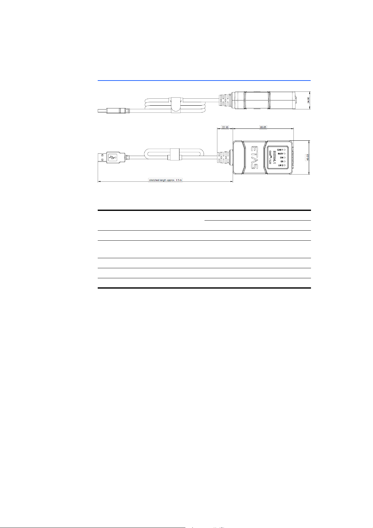
6.6 Mechanical Data
Fig. 6-2 Dimensions
Housing dimensions (H x W x D) 24 mm x 48 mm x 86.7 mm
0.8" x 1.6" x 2.52"
Length of the integrated USB cable 1.5 m / 4.9 ft
Weight Approx. 150 g / 5.291 oz. (with USB
cable)
Housing Nylon, rubberized
Connection on PC side USB connector, type A
Connection on bus side Nine-pin DSUB connector (DIN 41652)
ES584.1 – User’s Guide 36
Page 37
ETAS Technical Data
Note
Note
Note
6.7 System Requirements
6.7.1 Hardware
PC with USB port
PC IBM-compatible PC
USB port USB 2.0 full speed (480 Mbit/s)
Operating system Windows 7
Driver ES584.1 USB driver
Configuration Plug & play
Power supply
The product is powered via the USB port of a PC or a drive recorder. The module
does not require an external power supply.
The module must be operated directly at the USB port of a PC, a drive recorder
or an active hub, whose USB interface meets the requirements stated in the
table.
The use of USB cables to extend the connection between ES584.1 and the PC
or drive recorder is not permitted.
USB 2.0 high power (500 mA)
USB 3.0
USB socket type A
Windows 8
Windows 10
The module does not support USB 1.0 interfaces.
Prerequisite for successful initialization of the module
A specific USB driver must be installed on the PC for operating the ES584.1 (see
chapter
Windows user rights
Ensure that you have the necessary Windowsuser rights for installation of the
USB driver (administrator rights).
Additional requirements
The PC must also meet the minimum requirements of the application program
used (e.g. INCA). Please see the corresponding software documentation for
details of the minimum requirements for INCA.
ES584.1 – User’s Guide 37
4.3 on page 24).
Page 38

ETAS Technical Data
Note
Note
General information
The INCA application software supports up to four ES584.1 modules at the same
time.
Power manager
Almost all laptops and many desktop computers have a power management
function (power manager). Power managers deactivate the CPU for a certain
time. However, this compromises the accuracy of time management in your
application.
If you have strict time management requirements for your application (timecontrolled transfer of messages, time-controlled evaluations), you must deacti
vate this power manager.
The power management settings are adjusted:
• In the BIOS setup
• In the Windows Control Panel (e.g. object energy options).
-
This document does not provide detailed descriptions of how the power manager can be deactivated.
ES720.1 and ES820.1 drive recorders
The ES584.1 module can be operated on the USB port of ES720.1 and ES820.1
drive recorders.
ES584.1 – User’s Guide 38
Page 39
ETAS Technical Data
Note
6.7.2 Software
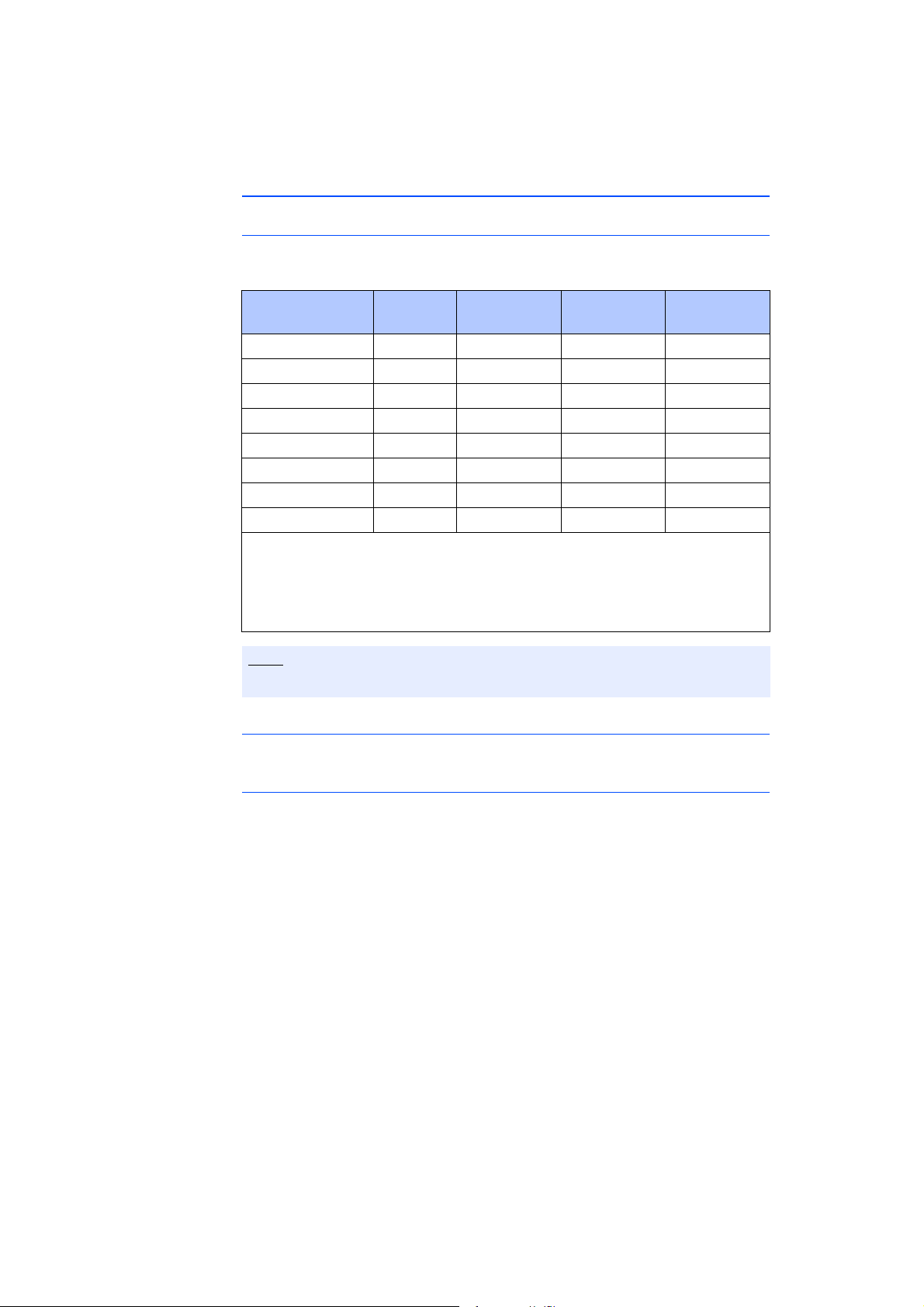
Supported applications and software requirements
For operation of the ES584.1 and for data capture, you require software in the
following versions or higher:
Application/protocol
CAN monitoring MC
CAN output MC
CCP MC
KWP on CAN MC
UDS MC
XCP on CAN MC
OBD-on-CAN MC, DS
LIN monitoring MC
Classification
1)
1)
1)
1)
1)
1)
1)
HSP INCA INCA
V11.6.0 V7.2.6 -
V11.6.0 V7.2.6 -
V11.6.0 V7.2.6 -
V11.6.0 V7.2.6 -
V11.6.0 V7.2.6 -
V11.6.0 V7.2.6 -
2)
V11.6.0 V7.2.6 ODX-LINK
V11.6.0 V7.2.6 LIN
add-on
4)
1)
: MC: Measurement and calibration
2)
: MC, DS: ECU diagnostics
3)
: INCA V7.2.6 and higher, also INCA add-on ODX-LINK V7.2.x and higher
4)
: INCA V7.2.6 and higher, also INCA add-on LIN V7.2.x and higher
It is not possible to operate the ES584.1 with older software versions.
Driver
ES584.1 USB driver
Supported software interfaces
3)
ETAS offers the "ECU and Bus Interfaces – Integration Package" (EBI-IP) software
development kit for integration of the ES584.1 module and the J2534 interface
into application software from third-party manufacturers.
The software development kit can be downloaded free-of-charge from the
dow
nload center on the ETAS website.
ES584.1 – User’s Guide 39
Page 40

ETAS Technical Data
6.8 Electrical Data
6.8.1 Voltage Supply
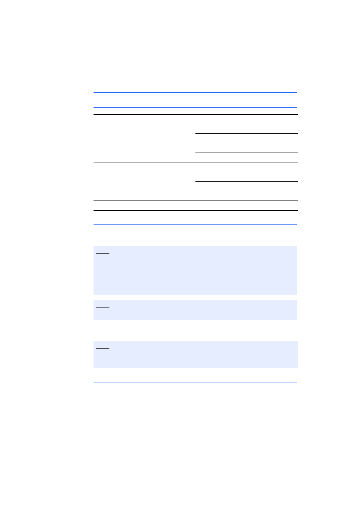
Operating voltage 4.75 V to 5.25 V DC
Supply via the USB port (see chapter
6.7.1 on page 37)
Current consumption, max. (during
oper
ation)
6.8.2 CAN Interface
CAN One interface,
Standard ISO 11898-1, ISO 15765-4,
Protocols CAN V2.0a (standard identifier),
Transmission speed High-speed CAN/CAN FD header:
CAN interface clients Max. 2
Controller ARM Cortex MCU
Transceiver (physical layer) TJA1044G
350 mA at 5.0 V DC
isolated from the USB port,
each channel can be configured separately
ISO 11898-2:2015
CAN V2.0b (extended identifier)
CAN FD
(ISO/CD 11898-1:2015; Bosch CAN FD
specification V1.0
Max. 1 MBaud for 20 m bus length
CAN FD (data): Max. 5 Mbit/s (operating temperature range)
CAN FD (data): Max. 8 Mbit/s (room
temperature
[non-ISO])
)
ES584.1 – User’s Guide 40
Page 41

ETAS Technical Data
6.8.3 LIN Interface
LIN One interface,
Standard ISO 17987 Part 1-7; LIN V2.2A,
Controller LIN core (FPGA)
Transceiver (physical layer) TLE7259
LIN reference voltage V
LIN V
(external) 12 V LIN systems:
BAT
Operating modes Master or slave,
LIN interface clients Max. 2
Clients and operating modes Client 1: Master or slave,
Clients and LIN standard Client 1:
Electrical isolation Interface separated from the other
1)
: Selection of internal LIN V
2)
: Support for master operating mode by INCA currently in preparation
isolated from the USB port
compatible with LIN V1.3, LIN V2.0 and
LIN V2.1
12 V LIN systems:
BAT
internal from the module or
V
BAT
external from the LIN bus,
can be selected in the application soft-
1)
ware
24 V LIN systems:
external from the LIN bus
V
BAT
8 V to 18 V
24 V LIN systems:
16 V to 36 V
can be selected in the application soft-
2)
ware
Client 2: Slave
ISO 17987 Part 1-7, LIN V2.2A,
LIN V1.3, LIN V2.0 or LIN V2.1
Client 2:
Compatible with the LIN standard used
by Client
interfa
by INCA currently in preparation
BAT
1
ces
ES584.1 – User’s Guide 41
Page 42
ETAS Technical Data
51
96
Note
6.9 Terminal Assignment
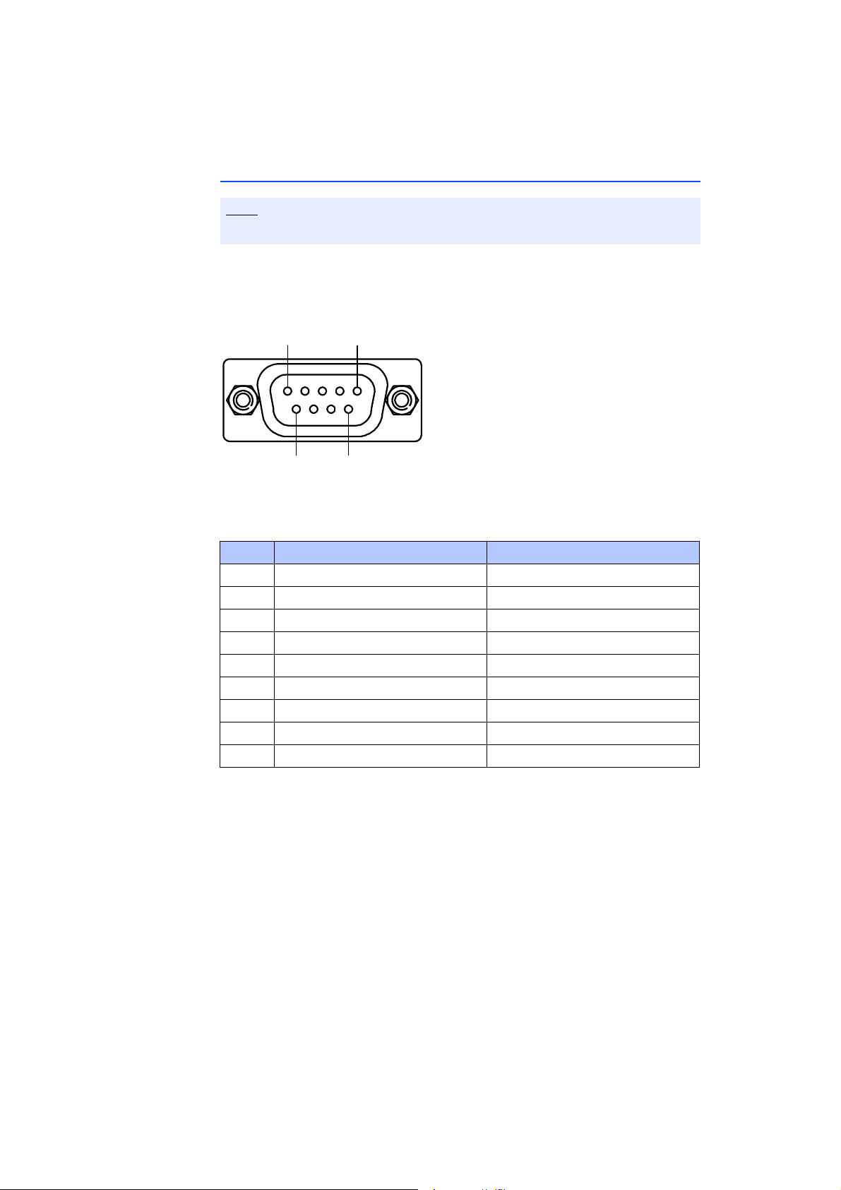
All connections are shown with view of the module interfaces.
The CAN bus is connected to the ES584.1 CAN FD and LIN Bus Interface USB
Module via the nine-pin DSUB connector (see Fig. 6-3).
Fig. 6-3 ES584.1 DSUB connector
Pin Signal Meaning
1 N.C. Not connected
2 CAN Low CAN Low
3 GND 1 Ground 1
4 N.C. Not connected
5 N.C. Not connected
6 GND 2 Ground 2
7 CAN High CAN High
8 LIN LIN
9 LIN V
A nine-pin DSUB connector is connected to the
BAT
UBAT for LIN
"CAN/LIN" socket.
ES584.1 – User’s Guide 42
Page 43
ETAS Cables and Accessories
51
96
51
96
1 2 3 4 5 6 7 8 9
1 2 3 7 9
3 2 5 7 9
Shell
6
6
Shell
Shell
PlugA
Plug1
Plug2
7 Cables and Accessories
7.1 Cable CBCF100
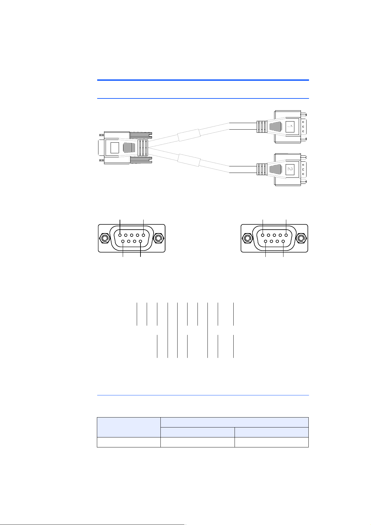
Fig. 7-1 CBCF100 cable
Fig. 7-2 CBCF100 cable: DSUB connection "1" and "2"
Fig. 7-3 CBCF100 cable wiring diagram
Assigning DSUB connectors "1" and "2" of the CBCF100 cable to the ES584.1
If a CBCF100 cable is used at the CAN/LIN interface of the ES584.1 module, the
interfaces are assigned to DSUB connectors "1" and "2" of the cable as follows:
ES584.1 CBCF100 cable in Fig. 7-1
Connection Connector "1" Connector "2"
CAN/LIN CAN LIN
ES584.1 – User’s Guide 43
Page 44
ETAS Cables and Accessories
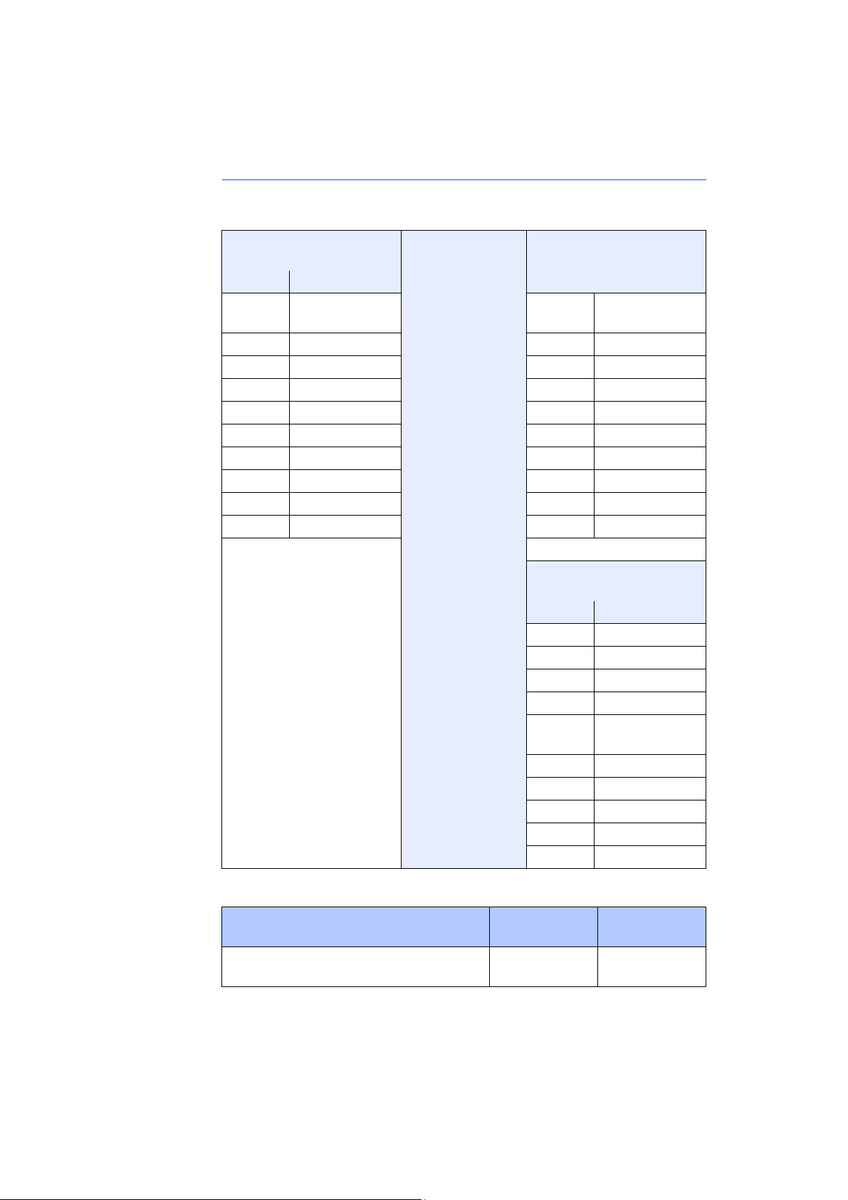
Pin assignment of the CBCF100 cable at the CAN/LIN interface of the ES584.1
The signals of the CAN/LIN interface of the ES584.1 module are assigned to
DSUB connectors "1" and "2" of the CBCF100 cable as follows:
DSUB socket
[ES584.1 connection]
DSUB connector "1"
[CAN]
Pin Signal Pin Signal
1
N.C. 1 DSUB socket,
pin 1
2
3
4
5
6
7
8
9 LIN V
CAN Low 2 CAN Low
GND 3 GND
N.C. 4 N.C.
N.C. 5 N.C.
GND 6 GND
CAN High 7 CAN High
LIN 8 N.C.
BAT
9 LIN V
Housing Shield Housing Shield
DSUB connector "2"
[LIN]
Pin Signal
1 N.C.
2 N.C.
3 GND
4 N.C.
5 DSUB socket,
pin 5
6 GND
7 LIN
8 N.C.
9 LIN V
Housing Shield
BAT
BAT
Order name Short name Order
number
CAN and FlexRay interface Y-cable, DSUB
– 2
x DSUB (9fc-9mc+9mc), 0m3
CBCF100.10m3
F 00K 107 939
ES584.1 – User’s Guide 44
Page 45
ETAS Cables and Accessories
7.2 CBAC180 Cable
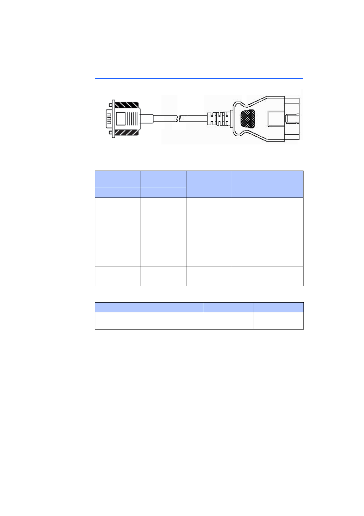
Fig. 7-4 CBAC180-2 cable
OBDII (J1962) adapter cable for the CAN interface
of the ES584.1
DSUB connection
OBD2 connection
Signal Note
Pin Pin
7 6 CAN High CAN High and CAN Low
in a
shielded twisted pair
2 14 CAN Low CAN High and CAN Low
in a
shielded twisted pair
8 3 LIN LIN and LIN GND in a
shielded twiste
d pair
4 11 LIN GND LIN and LIN GND in a
9 16 LIN V
BAT
shielded twiste
LIN UBAT
d pair
3 5 CAN GND CAN GND
Order designation Short name Order number
CAN interface cable, OBDII J1962 –
DSUB (1
6mc-9fc), 2 m
CBAC180.0-2 F-00K-107-300
ES584.1 – User’s Guide 45
Page 46

ETAS Cables and Accessories
CBH500-2
F00K106276
CAN/ L IN /F LX
0000
FM H 1
FMH 1
CBCX130.1-2
F00K 103 784
CAN
FM H1
Note
Note
7.3 CBH500 Cable
Fig. 7-5 CBH500 cable
The CBH500 cable only supports one CAN channel.
Order designation Short name Order number
CAN, LIN and FlexRay interface cable,
DSUB-DSUB (
9fc - 9mc + 9fc), 2 m
CBH500-2 F-00K-106-276
7.4 CBCX130 Cable
Fig. 7-6 CBCX130
The CBH500 cable only supports one CAN channel.
Order designation Short name Order number
CAN interface cable, DSUB – DSUB (9fc9m
c), 2 m
cable
CBCX130-2 F-00K-103-784
ES584.1 – User’s Guide 46
Page 47
ETAS Cables and Accessories
5
4
3
2
1
6
7
8
9
5
4
3
2
1
9
8
7
6
120 Ohm
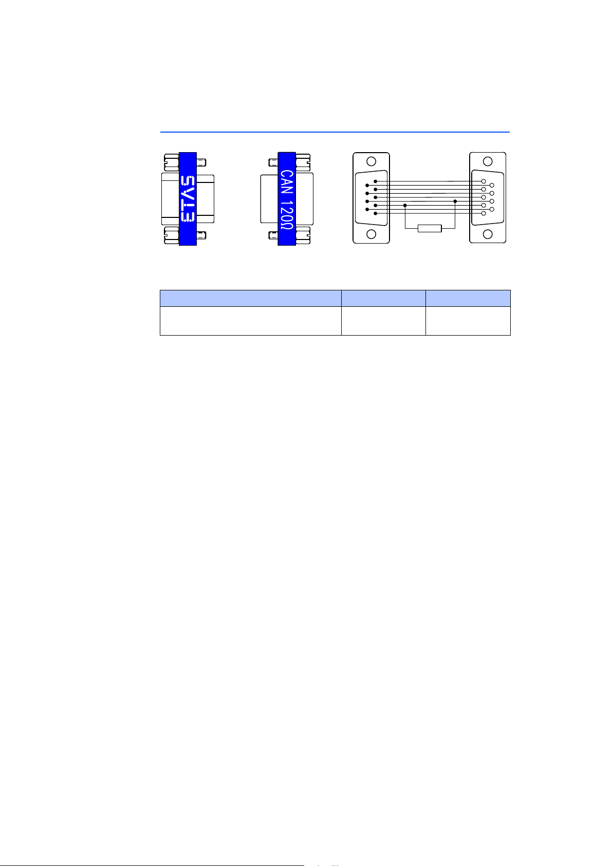
7.5 CBCX131.1-0 Adapter
Fig. 7-7 CBCX131.1-0 terminating resistor
CAN 120 ohm terminating resistor, 2xDSUB (9fc+9mc)
Order designation Short name Order number
CAN 120 ohm terminating resistor,
2xDSUB (9fc+9mc)
CBCX131-0 F-00K-103-786
ES584.1 – User’s Guide 47
Page 48

ETAS Cables and Accessories
ES584.1 – User’s Guide 48
Page 49
ETAS Order Information
8 Order Information
8.1 ES584.1 CAN FD and LIN Bus Interface USB Module
Order name Short name Order number
ES584.1 CAN FD and LIN
USB Module
Scope of supply
ES584.1 CAN FD and LIN
USB Module,
CBCF100.1 cable, ES584.1_DVD,
"Content of this Package" list,
ES58x_ETAS_Safety_Advice,
China-RoHS-leaflet_Compact_green_cn
Bus Interface
Bus Interface
ES584.1 F-00K-110-831
8.2 Accessories
Order name Short name Order number
CAN and FlexRay interface Y-cable,
DSUB – 2 x DSUB
CAN, LIN and FlexRay interface cable,
DSUB-DSUB (
CAN interface cable, OBDII J1962 –
DSUB (1
CAN interface cable, DSUB – DSUB (9fc9m
CAN 120 ohm terminating resistor,
2xDSUB (9fc+9mc)
6mc-9fc), 2 m
c), 2 m
(9fc-9mc+9mc), 0m3
9fc - 9mc + 9fc), 2 m
CBCF100.1-0m3 F-00K-107-939
CBH500-2 F-00K-106-276
CBAC180.0-2 F-00K-107-300
CBCX130-2 F-00K-103-784
CBCX131-0 F-00K-103-786
ES584.1 – User’s Guide 49
Page 50

ETAS Order Information
ES584.1 – User’s Guide 50
Page 51

ETAS ETAS Contact Addresses
9 ETAS Contact Addresses
ETAS HQ
ETAS GmbH
Borsigstraße 14 Phone: +49 711 3423-0
70469 Stuttgart Fax: +49 711 3423-2106
Germany WWW:
ETAS Subsidiaries and Technical Support
For details of your local sales office as well as your local technical support team
and product hotlines, take a look at the ETAS website:
www.etas.com
ETAS subsidiaries WWW:
ETAS technical support WWW: www.etas.com/en/hotlines.php
www.etas.com/en/contact.php
ES584.1 – User’s Guide 51
Page 52

ETAS ETAS Contact Addresses
ES584.1 – User’s Guide 52
Page 53

ETAS Figures
Figures
Fig. 3-1 ES584.1...................................................................................................... 13
Fig. 3-2 ES584.1 block diagram ............................................................................... 16
Fig. 3-3 Voltage supply on the LIN bus (pin assignment on the CBCF100 cable)....... 18
Fig. 3-4 ES584.1 LEDs.............................................................................................. 20
Fig. 4-1 Windows Device Manager .......................................................................... 27
Fig. 4-2 Windows information note ......................................................................... 28
Fig. 6-1 WEEE symbol.............................................................................................. 35
Fig. 6-2 Dimensions................................................................................................. 36
Fig. 6-3 ES584.1 DSUB connector............................................................................ 42
Fig. 7-1 CBCF100 cable ........................................................................................... 43
Fig. 7-2 CBCF100 cable: DSUB connection "1" and "2".......................................... 43
Fig. 7-3 CBCF100 cable wiring diagram................................................................... 43
Fig. 7-4 CBAC180-2 cable ....................................................................................... 45
Fig. 7-5 CBH500 cable ............................................................................................ 46
Fig. 7-6 CBCX130 cable .......................................................................................... 46
Fig. 7-7 CBCX131.1-0 terminating resistor .............................................................. 47
ES584.1 – User’s Guide 53
Page 54

Figures ETAS
ES584.1 – User’s Guide54
Page 55

ETAS Index
Index
A
Accident prevention 9
Administrator rights 31, 37
Application Areas 14
Applications
Software requirements 39
B
Bus terminating resistor, CAN 16
C
Cable
CBAC180 45
CBCF100 43
CBCX130 46
CBH500 46
CAN bus terminating resistor, 16
CAN FD Interface (CAN) 16
CAN Interface 40
CBCX131.1-0 Adapter 47
CD-ROM 23
Cleaning 34
Commissioning 23
ETAS Contact Addresses 51
F
Feature
CAN interface 16
H
Hardware Service Pack 21, 23
HSP 21, 23
I
INCA 14
Initialization 37
Installation Procedure 24
Interface
LIN 18
L
Labeling on the product 33
M
Maintenance 34
Multi-Client Support 21
D
Documentation 9
E
Electrical safety 10
ES584.1 J2534 Driver 30
ES584.1 – User’s Guide 55
O
ODX-LINK 14
Operating Mode
High-speed CAN 16
Operating mode
CAN FD 16
Page 56

Index ETAS
Operating Modes
CAN Interface 16
Operating state, display 20
Operation
Conventions 8
Use Case 8
Overview 13
P
Plug & play 23
Power manager 38
Presentation of Information 8
Product
Exclusion of liability 9
Product return 35
Properties 15
Q
Qualification, required 9
R
Recycling 35
S
Safety at work 9, 10
Safety notices
basic 9
Marking 7
Safety precautions 9
Scope of Supply 8
Software
Open Source 35
System requirements 39
Standards 34
System Requirements 37
WEEE return system 35
Y
Y-cable 18
T
Time Stamp 16
U
USB connection 28
USB Port 19
Use, intended 9
User rights 37
V
Voltage Supply 40
W
Waste electrical and electronic equip-
ment 35
WEEE 35
ES584.1 – User’s Guide56
 Loading...