

Page 1

ES5352.1 Signal Conditioning Board
User’s Guide
Page 2

Copyright
The data in this document may not be altered or amended without special notification from ETAS GmbH. ETAS GmbH undertakes no further obligation in relation to this document. The software described in it can only be used if the
customer is in possession of a general license agreement or single license. Using
and copying is only allowed in concurrence with the specifications stipulated in
the contract.
Under no circumstances may any part of this document be copied, reproduced,
transmitted, stored in a retrieval system or translated into another language
without the express written permission of ETAS GmbH.
© Copyright 2015-2018 ETAS GmbH, Stuttgart
The names and designations used in this document are trademarks or brands
belonging to the respective owners.
V1.0.0 R04 EN - 11.2018
2
Page 3

ETAS Contents
Contents
1 Introduction . . . . . . . . . . . . . . . . . . . . . . . . . . . . . . . . . . . . . . . . . . . . . . . . . . . . . . 5
1.1 Features . . . . . . . . . . . . . . . . . . . . . . . . . . . . . . . . . . . . . . . . . . . . . . . . . . . . 6
1.2 Basic Safety Instructions . . . . . . . . . . . . . . . . . . . . . . . . . . . . . . . . . . . . . . . . 8
1.2.1 Labeling of Safety Instructions . . . . . . . . . . . . . . . . . . . . . . . . . . . . . 8
1.2.2 General Safety Information . . . . . . . . . . . . . . . . . . . . . . . . . . . . . . . 8
1.2.3 Requirements for Users and Duties for Operators. . . . . . . . . . . . . . . 8
1.2.4 Intended Use . . . . . . . . . . . . . . . . . . . . . . . . . . . . . . . . . . . . . . . . . . 9
1.3 Identifications on the Product . . . . . . . . . . . . . . . . . . . . . . . . . . . . . . . . . . . 13
1.3.1 CE Marking . . . . . . . . . . . . . . . . . . . . . . . . . . . . . . . . . . . . . . . . . . 13
1.3.2 RoHS Conformity. . . . . . . . . . . . . . . . . . . . . . . . . . . . . . . . . . . . . . 13
1.3.3 KC Marking. . . . . . . . . . . . . . . . . . . . . . . . . . . . . . . . . . . . . . . . . . 14
1.4 Product Return and Recycling . . . . . . . . . . . . . . . . . . . . . . . . . . . . . . . . . . . 14
1.5 Declarable Substances . . . . . . . . . . . . . . . . . . . . . . . . . . . . . . . . . . . . . . . . 14
1.6 About this Manual . . . . . . . . . . . . . . . . . . . . . . . . . . . . . . . . . . . . . . . . . . . 14
1.6.1 Using this Manual . . . . . . . . . . . . . . . . . . . . . . . . . . . . . . . . . . . . . 15
2 Features and Functions . . . . . . . . . . . . . . . . . . . . . . . . . . . . . . . . . . . . . . . . . . . . . 17
2.1 Scope of Supply . . . . . . . . . . . . . . . . . . . . . . . . . . . . . . . . . . . . . . . . . . . . . 17
2.2 Power Supply . . . . . . . . . . . . . . . . . . . . . . . . . . . . . . . . . . . . . . . . . . . . . . . 17
2.3 Fuses . . . . . . . . . . . . . . . . . . . . . . . . . . . . . . . . . . . . . . . . . . . . . . . . . . . . . 18
2.4 Assembly . . . . . . . . . . . . . . . . . . . . . . . . . . . . . . . . . . . . . . . . . . . . . . . . . . 19
2.4.1 Assembling the DC/DC Converters . . . . . . . . . . . . . . . . . . . . . . . . 19
2.4.2 Assembling the Piggybacks . . . . . . . . . . . . . . . . . . . . . . . . . . . . . . 20
2.4.3 Assembling the ES5352.1 Signal Conditioning Board in the
ES5300.1-A Housing and in the ES5300.1-B Housing . . . . . . . . . . 20
2.4.4 Inserting the ES5352.1 Signal Conditioning Board into a Slot. . . . . 21
2.5 Configuration . . . . . . . . . . . . . . . . . . . . . . . . . . . . . . . . . . . . . . . . . . . . . . . 22
2.5.1 Configuring the Input Voltage of the DC/DC Converters . . . . . . . . 22
2.5.2 Configuring the I2C Addresses . . . . . . . . . . . . . . . . . . . . . . . . . . . 23
ES5352.1 Signal Conditioning Board - User’s Guide 3
Page 4

Contents ETAS
3 Pin Assignment and Connections . . . . . . . . . . . . . . . . . . . . . . . . . . . . . . . . . . . . . 25
3.1 Backplane Connector (CO200) . . . . . . . . . . . . . . . . . . . . . . . . . . . . . . . . . . 25
3.2 D-Sub62 (CO100) . . . . . . . . . . . . . . . . . . . . . . . . . . . . . . . . . . . . . . . . . . . . 27
3.3 Piggyback Connectors . . . . . . . . . . . . . . . . . . . . . . . . . . . . . . . . . . . . . . . . 28
3.3.1 "CO300" Connector (Piggyback 1) . . . . . . . . . . . . . . . . . . . . . . . . 28
3.3.2 "CO301" Connector (Piggyback 1) . . . . . . . . . . . . . . . . . . . . . . . . 29
3.3.3 "CO306" Connector (Piggyback 2) . . . . . . . . . . . . . . . . . . . . . . . . 30
3.3.4 "CO307" Connector (Piggyback 2) . . . . . . . . . . . . . . . . . . . . . . . . 31
3.4 Connectors on the Board . . . . . . . . . . . . . . . . . . . . . . . . . . . . . . . . . . . . . . 32
3.4.1 C0101. . . . . . . . . . . . . . . . . . . . . . . . . . . . . . . . . . . . . . . . . . . . . . 32
3.4.2 C0102. . . . . . . . . . . . . . . . . . . . . . . . . . . . . . . . . . . . . . . . . . . . . . 32
3.4.3 C0103. . . . . . . . . . . . . . . . . . . . . . . . . . . . . . . . . . . . . . . . . . . . . . 33
3.4.4 C0104. . . . . . . . . . . . . . . . . . . . . . . . . . . . . . . . . . . . . . . . . . . . . . 33
3.4.5 C0105. . . . . . . . . . . . . . . . . . . . . . . . . . . . . . . . . . . . . . . . . . . . . . 33
4 Technical Data and Norms . . . . . . . . . . . . . . . . . . . . . . . . . . . . . . . . . . . . . . . . . . 35
4.1 Technical Data . . . . . . . . . . . . . . . . . . . . . . . . . . . . . . . . . . . . . . . . . . . . . . 35
4.2 Fulfilled Standards and Norms . . . . . . . . . . . . . . . . . . . . . . . . . . . . . . . . . . . 36
5 Ordering Information . . . . . . . . . . . . . . . . . . . . . . . . . . . . . . . . . . . . . . . . . . . . . . 37
6 ETAS Contact Addresses . . . . . . . . . . . . . . . . . . . . . . . . . . . . . . . . . . . . . . . . . . . . 39
Index . . . . . . . . . . . . . . . . . . . . . . . . . . . . . . . . . . . . . . . . . . . . . . . . . . . . . . . . . . 41
ES5352.1 Signal Conditioning Board - User’s Guide4
Page 5

ETAS Introduction
CAUTION!
1 Introduction
This User’s Guide describes the ES5352.1 Signal Conditioning Board.
Some components of the ES5352.1 Signal Conditioning Board can be
damaged or destroyed by electrostatic discharges. Leave the plug-in
board in its transport packaging until it is installed.
Only remove, configure and install the ES5352.1 at a workplace that
is protected against electrostatic discharges.
This chapter contains information on the following topics:
• "Features" on page 6
• "Basic Safety Instructions" on page 8
• "Identifications on the Product" on page 13
• "CE Marking" on page 13
• "RoHS Conformity" on page 13
• "KC Marking" on page 14
• "Product Return and Recycling" on page 14
• "Declarable Substances" on page 14
• "About this Manual" on page 14
ES5352.1 Signal Conditioning Board - User’s Guide 5
Page 6
Introduction ETAS
Module 1
PB1_OUT1..15
PB1_IN1..9
PB2_OUT1..15
Module 2
PB2_IN1..9
DC/DC
DC/DC
DC/DC
DC/DC
SPI
DC/DC
DC/DC
DC/DC
DC/DC
I2C
Battery Nodes BN_B_0..5
1.1 Features
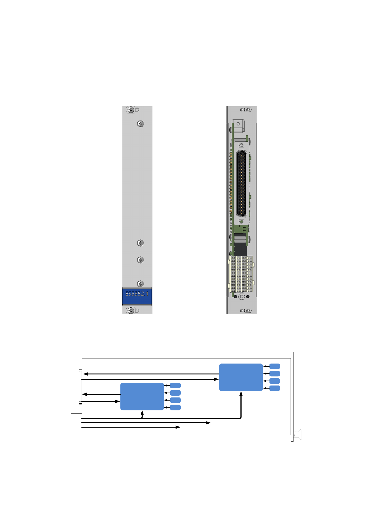
The ES5352.1 Signal Conditioning Board is used to accommodate two modules
for signal conditioning (example: PB1652LAMBDA.1-B Signal Conditioning for
Lambda Sensor Simulation).
Fig. 1-1 Front Panel and Plug-In Side of the ES5352.1 Signal Conditioning
Board
The function units of the ES5352.1 Signal Conditioning Board are shown in the
following block diagram:
Fig. 1-2 Block Diagram
ES5352.1 Signal Conditioning Board - User’s Guide6
Page 7
ETAS Introduction
CAUTION!
The 9 input and 15 output signals of each of the piggybacks are routed over the
62-pin D-Sub connector.
There is no protective circuitry for the inputs and outputs on the
ES5352.1 Signal Conditioning Board! If required, the customer must
provide this on the relevant piggyback.
To supply power to the piggybacks, up to four DC/DC converters can be installed
per module on the ES5352.1 Signal Conditioning Board. These are either supplied with +5 V or +12 V from the backplane.
There are fuses on the ES5352.1 to protect the backplane voltages.
ES5352.1 Signal Conditioning Board - User’s Guide 7
Page 8

Introduction ETAS
CAUTION!
WARNING!
DANGER!
Note
1.2 Basic Safety Instructions
Please adhere to the safety instructions in this manual to avoid injury to yourself
and others as well as damage to the device.
1.2.1 Labeling of Safety Instructions
The safety instructions contained in this manual are shown with the standard
danger symbol shown below:
The following safety instructions are used. They provide extremely important
information. Please read this information carefully.
indicates a low-risk danger which could result in minor or less serious
injury or damage if not avoided.
indicates a possible medium-risk danger which could lead to serious
or even fatal injuries if not avoided.
indicates a high-risk, immediate danger which could lead to serious
or even fatal injuries if not avoided.
1.2.2 General Safety Information
Please observe the Product Safety Notices ("ETAS Safety Notice") and the following safety notices to avoid health issues or damage to the device.
The User's Guide must be read prior to the startup of the product!
ETAS GmbH does not assume any liability for damages resulting from improper
handling, unintended use or non-observance of the safety precautions.
1.2.3 Requirements for Users and Duties for Operators
The product may be assembled, operated and maintained only if you have the
necessary qualifications and experience for this product. Improper use or use by
a user without sufficient qualification can put life at risk or cause damage to
health or property.
The system integrator is responsible for the safety of systems that use the
product!
General Safety at Work
Follow the existing regulations for work safety and accident prevention. All applicable regulations and laws regarding operation must be strictly adhered to when
using this product.
ES5352.1 Signal Conditioning Board - User’s Guide8
Page 9

ETAS Introduction
1.2.4 Intended Use
Application Area of the Product
The ES5352.1 Signal Conditioning Board is a plug-in board for the ES5300.1-A
Housing and the ES5300.1-B Housing for accommodating two modules for signal conditioning.
The ES5352.1 Signal Conditioning Board consists of:
• Two slots for signal conditioning modules,
• One SPI interface to the ES5300.1-A Housing or to the ES5300.1-B Housing for configuring modules,
•One I
2
C interface for reading board data,
• One output interface to the ECU,
• One digital interface for signals to battery node control,
• Piggyback power supply - up to four DC/DC converters per module are
required for this purpose.
The ES5321.2 must only ever be used in the ETAS ES5300 system housing
intended for this purpose and must not be operated as a stand-alone unit.
The intended use of the ES5321.2 in an ES5300.1-A Housing or ES5300.1-B
Housing is:
• Use as a component in industrial lab facilities or at industrial workplaces.
• Use as a hardware interface for ECUs in a hardware-in-the-loop test system.
• Use in conjunction with ETAS software that supports the ES5300.1-A
Housing and the ES5300.1-B Housing.
• Use as an interface in conjunction with software programs that operate
the standardized, documented and open APIs from ETAS software products.
The ES5352.1 Signal Conditioning Board is not intended to be used:
• Within a vehicle on the road.
• As part of a life support system.
• As part of a medical application.
• In applications where misuse can lead to injuries or damages.
• In environments in which conditions prevail that fall outside the specified
ranges (see "Ambient Conditions" on page 35),
• With signal conditioning that falls outside the specified ranges (see "Voltages, Currents and Power Consumption" on page 35).
ES5352.1 Signal Conditioning Board - User’s Guide 9
Page 10
Introduction ETAS
WARNING!
CAUTION!
Requirements for the Technical State of the Product
The product is designed in accordance with state-of-the-art technology and recognized safety rules. The product must only be operated in a technically flawless
state, in accordance with its intended purpose and in a safety-conscious and
hazard-aware manner under consideration of the documentation regarding the
product. If the product is not used in accordance with its intended purpose, its
product safety may be impaired.
Requirements for Operation
The following requirements are necessary for safe operation:
• Use the product only according to the specifications in the corresponding
User's Guide. If the product is used in any other way, product safety is no
longer ensured.
• Do not use the product in a wet or damp environment.
• Do not use the product in potentially explosive atmospheres.
Electrical Safety and Power Supply
Observe the regulations applicable at the operating location concerning electrical
safety as well as the laws and regulations concerning work safety.
Fire Hazard!
Only use fuses that comply with the specification in the User's Guide
for the product. Never bridge defective fuses!
Failure to observe the fuse specification can lead to excess currents,
short circuits and fires.
There is no protective circuitry for the inputs and outputs on the
ES5352.1 Signal Conditioning Board! If required, the customer must
provide this on the relevant piggyback.
Power Supply
The product is powered by the ES5300.1-A Housing or the ES5300.1-B Housing
via the PCIe backplane connector.
The electrical connection is made via the backplane connector CO200.
Insulation Requirements for lab power supplies to circuits connected to the HiLSystem:
• The power supply to live circuitry must be safely isolated from the supply
voltage. For example, use a car battery or a suitable lab power supply.
• Only use lab power supplies with dual protection for the supply network
(with double/reinforced insulation (DI/RI)). Lab power supplies that comply
with IEC/EN 60950 or IEC/EN 61010 meet this requirement.
• The lab power supply must be approved for use at a height of 2000 m and
in ambient temperatures of up to 40 °C.
ES5352.1 Signal Conditioning Board - User’s Guide10
Page 11
ETAS Introduction
WARNING!
WARNING!
CAUTION!
CAUTION!
De-energizing the plug-in board
Switch off the ES5300.1-A Housing or the ES5300.1-B Housing and external
power supplies and unplug the power plug and other connectors attached to the
plug-in board. Wait at least three minutes before removing the plug-in board.
Approved Cables
The signal lines must not exceed a maximum length of 3 m.
Fire hazard!
Use only approved cables for creating cable assemblies (e.g. for connecting the ECU and external loads). The cables used must, in particular, be suitable for the currents, voltages and temperatures which
occur and must be flameretardant in accordance with one of the following standards
IEC60332-1-2, IEC60332-2-2, UL2556/UL1581VW-1!
Requirements for the installation location
This is class A equipment. This equipment can cause radio interference in residential areas. Should that be the case, the operator may
be requested to institute reasonable measures.
Requirements for ventilation
The air circulation inside the ES5300.1-A Housing and the ES5300.1B Housing can be ensured only if all free slots are covered with front
plates. Otherwise, it may lead to overtemperatures and trip the overtemperature protection of the ES5300.1-A or the ES5300.1-B.
For this reason, install front plates in all free slots!
Transport and Installation
To avoid damages to the hardware from electrostatic discharge, please observe
the following precautionary measures:
Some components of the ES5352.1 can be damaged or destroyed by
electrostatic discharges. Leave the plug-in board in its transport packaging until it is installed.
Only remove, configure and install the ES5352.1 at a workplace that
is protected against electrostatic discharges.
ES5352.1 Signal Conditioning Board - User’s Guide 11
Page 12
Introduction ETAS
CAUTION!
CAUTION!
In order to prevent damage to the plug-in board and the LABCAR
Housing and thereby also avoid damage to property or health,
observe the installation instructions and information contained in the
relevant User's Guide.
If cards (e.g. for startup or calibration) are unlocked but not completely removed from the housing, they have to be pulled out far
enough that the distance between the respective card and the backplane of the housing is at least 1 cm! Otherwise, contacts may be
established between the cards and lead to their destruction.
Connecting / Disconnecting Devices
To avoid injuries and hardware damages, please observe the following precautionary measures:
• Do not apply any voltages to the connections of the ES5352.1 that do not
correspond to the specifications of the respective connection. The exact
specification of the I/O hardware is located in the manuals of the corresponding boards.
• Do not connect or disconnect any devices while the ES5300.1-A Housing,
the ES5300.1-B Housing or connected devices are switched on. First,
switch off the ES5300.1-A Housing or the ES5300.1-B Housing by shutting down the real-time PC and by activating the On/Off switch at the
rear, then unplug the power plug.
• When plugging in connectors, ensure that they are inserted straight and
no pins are bent.
Maintenance
The device does not require maintenance.
Repairs
If an ETAS hardware product needs to be repaired, return the product to ETAS.
Cleaning
The product is not expected to require cleaning.
ES5352.1 Signal Conditioning Board - User’s Guide12
Page 13
ETAS Introduction
1.3 Identifications on the Product
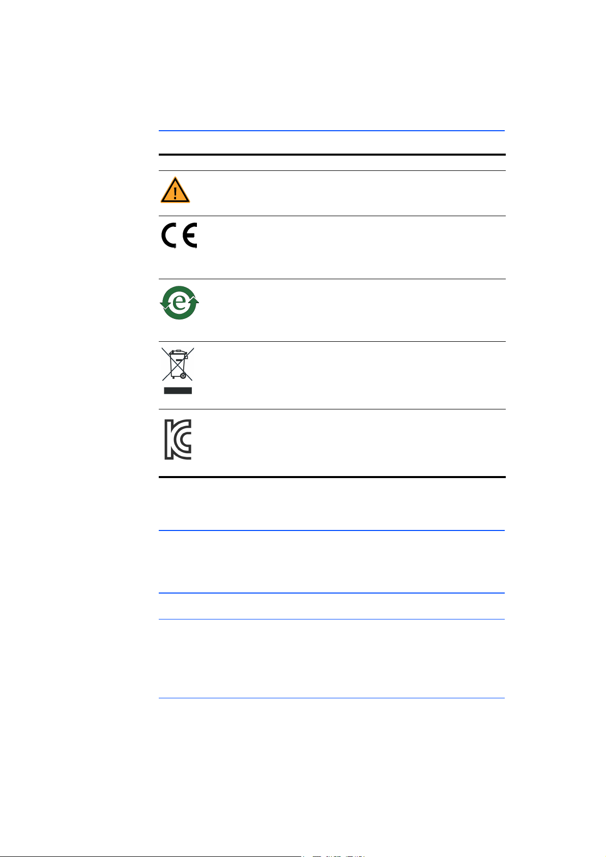
The following symbols are used for identifying the product:
Symbol Description
Before using the product, carefully read the User’s Guide!
Identification for CE conformity,
see "CE Marking" on page 13
Identification for China RoHS,
see "RoHS Conformity" on page 13
Identification for conformity with WEEE directive,
see "Product Return and Recycling" on page 14
Observe the information in the chapter "Technical Data and Norms"
on page 35.
1.3.1 CE Marking
ETAS confirms that the product meets the product-specific applicable European
Directives with the CE marking affixed to the product or its packaging. The CE
Declaration of Conformity for the product is available upon request.
1.3.2 RoHS Conformity
European Union
The EU Directive 2002/95/EU limits the use of certain dangerous materials for
electrical and electronic devices (RoHS conformity).
ETAS confirms that the product corresponds to this directive which is applicable
in the European Union.
China
ETAS confirms that the product meets the product-specific applicable guidelines
of the China RoHS (Management Methods for Controlling Pollution Caused by
Electronic Information Products Regulation) applicable in China with the China
RoHS marking affixed to the product or its packaging.
Marking for KCC Conformity,
see "KC Marking" on page 14
ES5352.1 Signal Conditioning Board - User’s Guide 13
Page 14

Introduction ETAS
1.3.3 KC Marking
With the KC mark attached to the product and its packaging, ETAS confirms that
the product has been registered in accordance with the product-specific KCC
guidelines of the Republic of Korea.
1.4 Product Return and Recycling
The European Union (EU) has passed a directive called Waste Electrical and Electronic Equipment, or WEEE for short, to ensure that systems are set up throughout the EU for the collection, treatment and recycling of electronic waste.
This ensures that the devices are recycled in a resource-saving way representing
no danger to health or the environment.
Fig. 1-3 WEEE Symbol
The WEEE symbol on the product or its packaging shows that the product must
not be disposed of as residual garbage.
The user is obliged to collect the old devices separately and return them to the
WEEE take-back system for recycling.
The WEEE Directive concerns all ETAS devices but not external cables or batteries.
For more information on the ETAS GmbH Recycling Program, contact the ETAS
sales and service locations (see "ETAS Contact Addresses" on page 39).
1.5 Declarable Substances
European Union
Some products from ETAS GmbH (e.g. modules, boards, cables) use components
with materials that are subject to declaration in accordance with the REACH regulation (EU) no.1907/2006.
Detailed information is located in the ETAS download center in the customer
information "REACH Declaration" (www.etas.com/Reach
continuously being updated.
1.6 About this Manual
This manual consists of the following chapters:
• "Introduction" on page 5
This chapter
• "Features and Functions" on page 17
This chapter describes the features and functions of the components of
the ES5352.1 Signal Conditioning Board.
• "Pin Assignment and Connections" on page 25
This section describes the various connectors of the ES5352.1 Signal Conditioning Board.
). This information is
ES5352.1 Signal Conditioning Board - User’s Guide14
Page 15

ETAS Introduction
• "Technical Data and Norms" on page 35
This chapter contains the technical data on the ES5352.1 Signal Conditioning Board. In addition, fulfilled standards and norms are listed.
1.6.1 Using this Manual
Representation of Information
All activities to be carried out by the user are shown in what we call a "UseCase" format, i.e. the target to be achieved is defined briefly in the title and the
individual steps necessary to achieve this target are then listed. The information
is displayed as follows:
Target definition
Any introductory information...
1. Step 1
Possibly an explanation of step 1...
2. Step 2
Possibly an explanation of step 2...
Any concluding remarks...
Concrete example:
To create a new file
If you want to create a new file, no other file may be open.
1. Select File → New.
The "Create file" dialog box appears.
2. Enter a name for the file in the "File name" field.
The file name must not exceed 8 characters.
3. Click OK.
The new file is created and saved under the name specified. You can now work
with the file.
Typographic Conventions
The following typographic conventions are used:
Select File → Open. Menu commands are shown in boldface/
blue.
Click OK. Buttons are shown in boldface/blue.
Press <ENTER>. Keyboard commands are shown in angled
brackets in block capitals.
ES5352.1 Signal Conditioning Board - User’s Guide 15
Page 16

Introduction ETAS
Note
The "Open File" dialog box
appears.
Select the file setup.exe. Text in drop-down lists, program code, as
A conversion between the file types
logical and arithmetic is not possible.
Important notes for the user are shown as follows:
Important note for the user.
Names of program windows, dialog boxes,
fields etc. are shown in quotation marks.
well as path and file names are shown in
the Courier font.
Content markings and newly introduced
terms are shown in italics.
ES5352.1 Signal Conditioning Board - User’s Guide16
Page 17
ETAS Features and Functions
CO300
CO301
IC300
IC301
IC302
IC303
IC306
IC304
IC303
IC307
CO306
CO307
2 Features and Functions
This chapter describes the features and functions of the components of the
ES5352.1 Signal Conditioning Board.
• "Power Supply" on page 17
• "Fuses" on page 18
• "Assembly" on page 19
– "Assembling the DC/DC Converters" on page 19
– "Assembling the Piggybacks" on page 20
– "Assembling the ES5352.1 Signal Conditioning Board in the
ES5300.1-A Housing and in the ES5300.1-B Housing" on page 20
– "Inserting the ES5352.1 Signal Conditioning Board into a Slot"
on page 21
• "Configuration" on page 22
– "Configuring the Input Voltage of the DC/DC Converters" on page 22
– "Configuring the I2C Addresses" on page 23
2.1 Scope of Supply
You can find the scope of supply in chapter "Ordering Information" on page 37
2.2 Power Supply
To supply the piggybacks with power, up to four DC/DC converters per module
can be accommodated on the ES5352.1 Signal Conditioning Board. Their primary function is voltage stabilization and galvanic isolation.
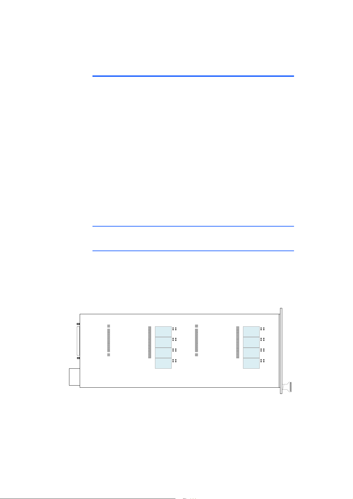
The output voltages DC1 - DC4 of the converters are connected with the connector strip CO301 or C307 (see ""CO301" Connector (Piggyback 1)"
on page 29 and ""CO307" Connector (Piggyback 2)" on page 31) and can thus
be used to supply power to a piggyback.
Fig. 2-1 Position of the DC/DC Converters on the ES5352.1 Signal Condition-
ing Board
ES5352.1 Signal Conditioning Board - User’s Guide 17
Page 18
Features and Functions ETAS
FU204 FU201
FU200FU202
Refer to the following table for the assignment of the DC/DC converters to the
signals at the connectors.
CO301 Connector CO307 Connector
Slot Signal Slot Signal
IC300 PB1_DC1_xxx IC306 PB2_DC1_xxx
IC301 PB1_DC2_xxx IC304 PB2_DC2_xxx
IC302 PB1_DC3_xxx IC305 PB2_DC3_xxx
IC303 PB1_DC4_xxx IC307 PB2_DC4_xxx
Tab. 2-1 Assignment of the DC/DC Converters to Signals at Connectors
The converters are fed with voltages from the backplane (see "Configuring the
Input Voltage of the DC/DC Converters" on page 22). The
TRACO POWER TEN 3 Series is one example of a usable type of DC/DC converter.
2.3 Fuses
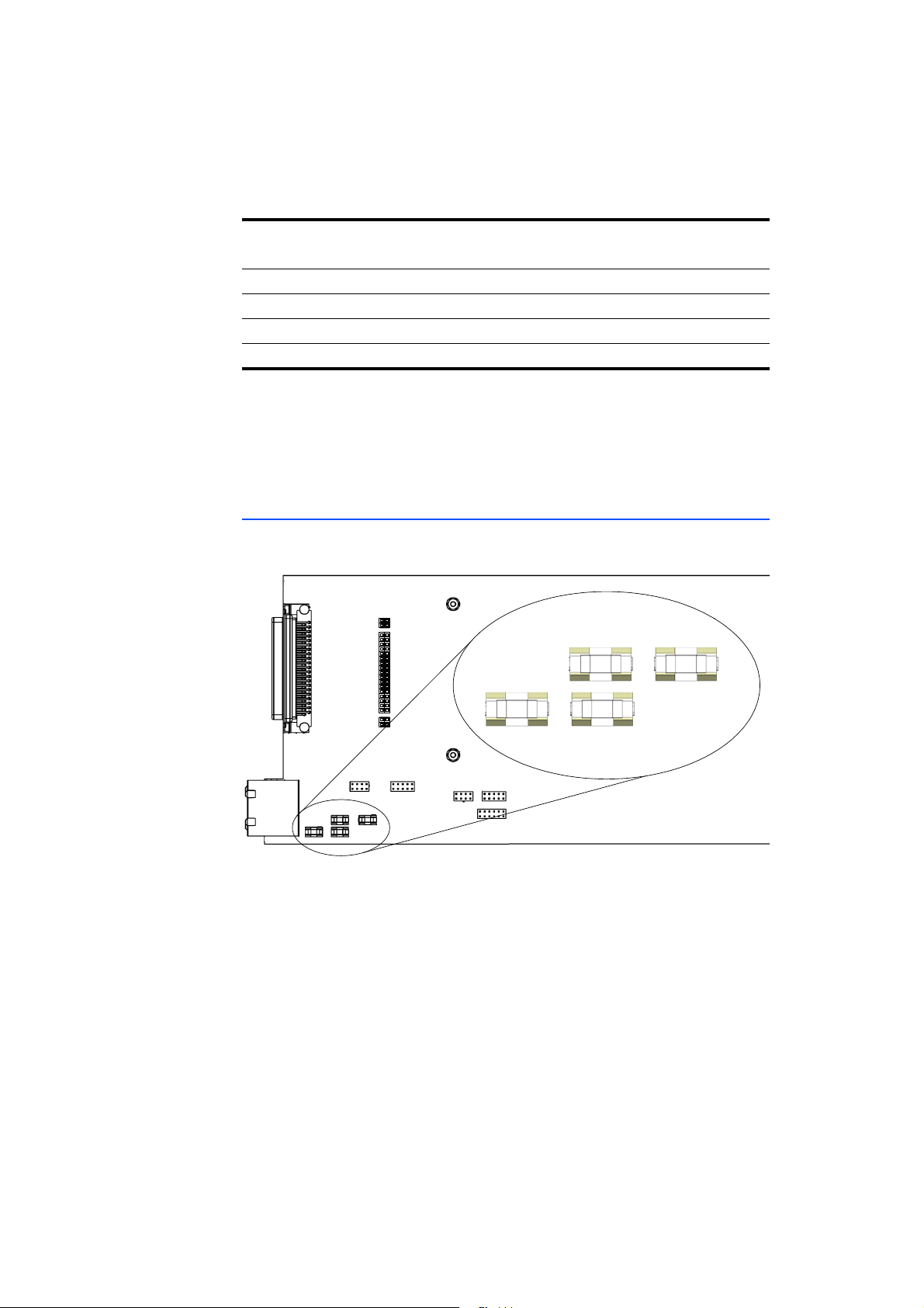
There are four fuses on the ES5352.1 Signal Conditioning Board to protect the
backplane voltages.
Fig. 2-2 Position of the Fuses on the ES5352.1
ES5352.1 Signal Conditioning Board - User’s Guide18
Page 19
ETAS Features and Functions
WARNING!
Note
The specification of the fuses is as follows:
Fuse Type Specification Protection of
(voltage)
FU200 NANO2® Slo-Blo
Fuse 452/454 Series
FU201 NANO2® Slo-Blo
Fuse 452/454 Series
FU202 NANO2® Slo-Blo
Fuse 452/454 Series
FU204 NANO2® Slo-Blo
Fuse 452/454 Series
®
T 3 A VCC12
(+12 V)
®
T 3 A VCC3_3
(+3.3 V)
®
T 1 A VCC5
(+5 V)
®
T 0.5 A VSS12
(-12 V)
Tab. 2-2 Fuses
Fire Hazard!
Only use fuses that comply with the specification in the User's Guide
for the product. Never bridge defective fuses!
Failure to observe the fuse specification can lead to excess currents,
short circuits and fires.
2.4 Assembly
This section contains details of how to assemble the necessary components:
• "Assembling the DC/DC Converters" on page 19
• "Assembling the Piggybacks" on page 20
• "Assembling the ES5352.1 Signal Conditioning Board in the ES5300.1-A
Housing and in the ES5300.1-B Housing" on page 20
• "Inserting the ES5352.1 Signal Conditioning Board into a Slot"
on page 21
2.4.1 Assembling the DC/DC Converters
The DC/DC converter type Traco TEN 3-1222 is suitable for supplying power to
the piggybacks.
For a PB1652LAMBDA.1-B module in slot 1, IC300 and IC301 must be assembled; for slot 2, IC306 and IC304 must be assembled (see Fig. 2-1 on page 17).
For configuring the power supply, the solder bridges BR301 and BR303 and/or
BR308 and BR310 must be soldered in to suit slot use (see "Configuring the
Input Voltage of the DC/DC Converters" on page 22).
Use lead-free solder! Ensure that there is not too much heat at the contacts –
too much heat can damage the converters and the board!
ES5352.1 Signal Conditioning Board - User’s Guide 19
Page 20
Features and Functions ETAS
CAUTION!
CAUTION!
CAUTION!
2.4.2 Assembling the Piggybacks
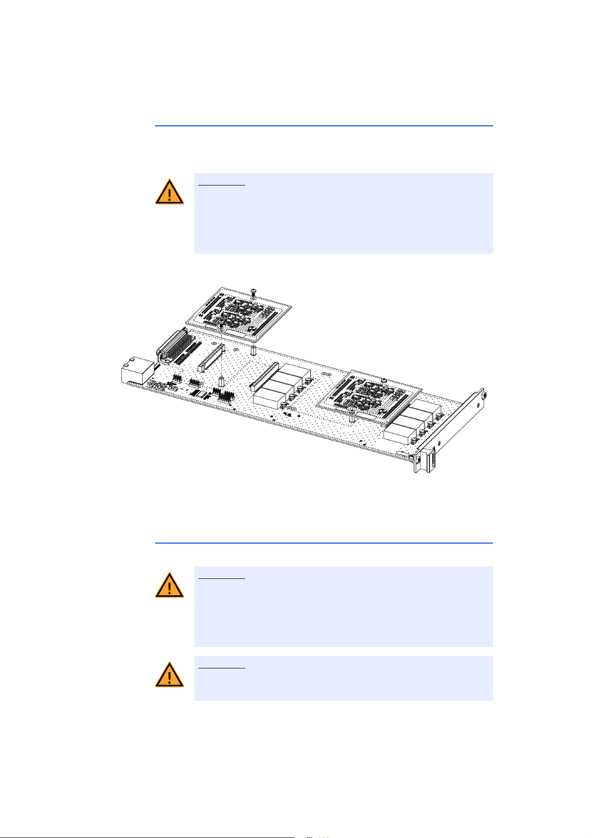
Place the pin strips of the module onto the contact strips of the ES5352.1 Signal
Conditioning Board so they correspond to each other, i.e. interrupted pin strip to
interrupted contact strip and continuous pin strip to continuous contact strip.
If the contact pins of the piggyback are not positioned exactly over
the contact strip, these could be bent and the piggyback thus damaged.
Before pushing the module into the contact strips, check the position
is absolutely right!
The piggybacks are secured on the spacers with two M3 x 6 screws (see Fig. 2-3).
Fig. 2-3 Assembling the Piggybacks
The connectors are designed for 100 cycles of operation.
2.4.3 Assembling the ES5352.1 Signal Conditioning Board in the ES5300.1-A Housing and in the ES5300.1-B Housing
Before you start, ensure you have ESD-compliant conditions at your workplace.
Some components of the ES5352.1 Signal Conditioning Board can be
damaged or destroyed by electrostatic discharges. Leave the plug-in
board in its transport packaging until it is installed.
Only remove, configure and install the ES5352.1 at a workplace that
is protected against electrostatic discharges.
Do not install any boards while the ES5100.1 Desktop Housing is
powered on!
ES5352.1 Signal Conditioning Board - User’s Guide20
Page 21
ETAS Features and Functions
CAUTION!
Note
CAUTION!
1. Shut down the Real-Time PC and disconnect the
power supply to the ES5300.1-A Housing or the
ES5300.1-B Housing by switching it off on the back
of the device.
2. Wait a few minutes until the components (capacitors etc.) have discharged.
2.4.4 Inserting the ES5352.1 Signal Conditioning Board into a Slot
When sliding in boards that are wider than slot width (5 HP), there
may be a collision with an adjacent board or front panels of adjacent
slots. This can cause damage to or even destroy the boards to be
installed.
Make sure that the ES5352.1 with its piggybacks either adheres to
the maximum width of 5 HP or that the neighboring slot is empty and
that there are no assembled cover plates stopping the board from
being inserted!
1. Position the ES5352.1 (gripping plate on the front
panel must be pointing down!) into the top and
bottom rail of the slot and insert it slightly.
2. Open the front door of the ES5300.1-A or the
ES5300.1-B after first loosening the three upper
Phillips screws (see "ES5300.1-A Housing - User’s
Guide" or "ES5300.1-B Housing - User´s Guide").
3. Carefully slide in the carrier board until the backplane connector of the ES5352.1 is completely
plugged in to the backplane socket.
When sliding in the board, please make sure there
are no cables in the way – if necessary, pull the cords
into the front door area.
4. Secure the carrier board by tightly screwing on the
slot bracket.
The air circulation inside the ES5300.1-A Housing or the ES5300.1-B
Housing can be ensured only if all free slots are covered with front
plates. Otherwise, it may lead to overtemperatures and trip the overtemperature protection of the ES5300.1-A or ES5300.1-B.
For this reason, install front plates in all free slots!
ES5352.1 Signal Conditioning Board - User’s Guide 21
Page 22
Features and Functions ETAS
Note
IC300
IC301
IC302
BR304 VCC5
VCC12
IC302
BR305
IC303
BR306 VCC5
VCC12
IC303
BR307
VCC5
VCC12
IC301
BR302
BR303
VCC5
VCC12
IC300
BR300
BR301
IC306
IC304
IC305
BR312 VCC5
VCC12
IC303
BR313
IC307
BR314 VCC5
VCC12
IC307
BR315
VCC5
VCC12
IC304
BR310
BR311
VCC5
VCC12
IC306
BR308
BR309
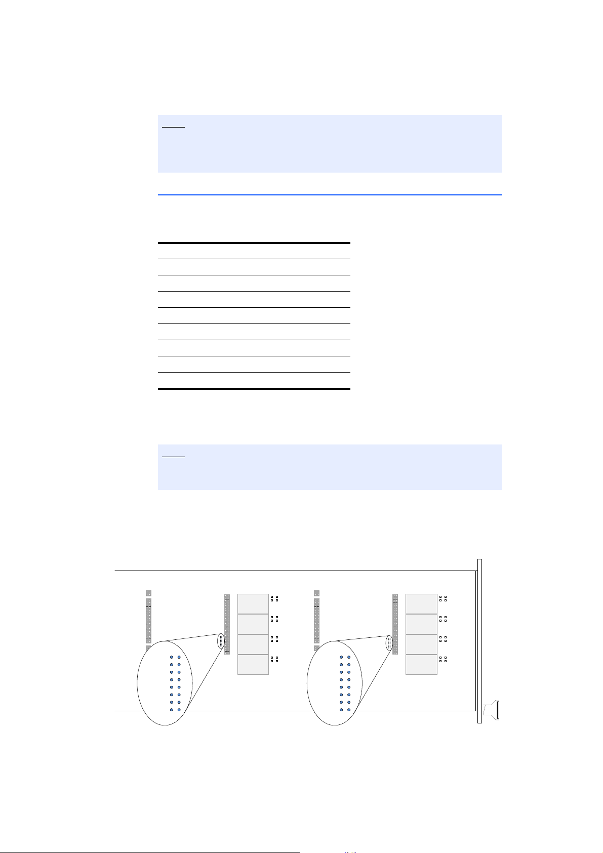
2.5 Configuration
2.5.1 Configuring the Input Voltage of the DC/DC Converters
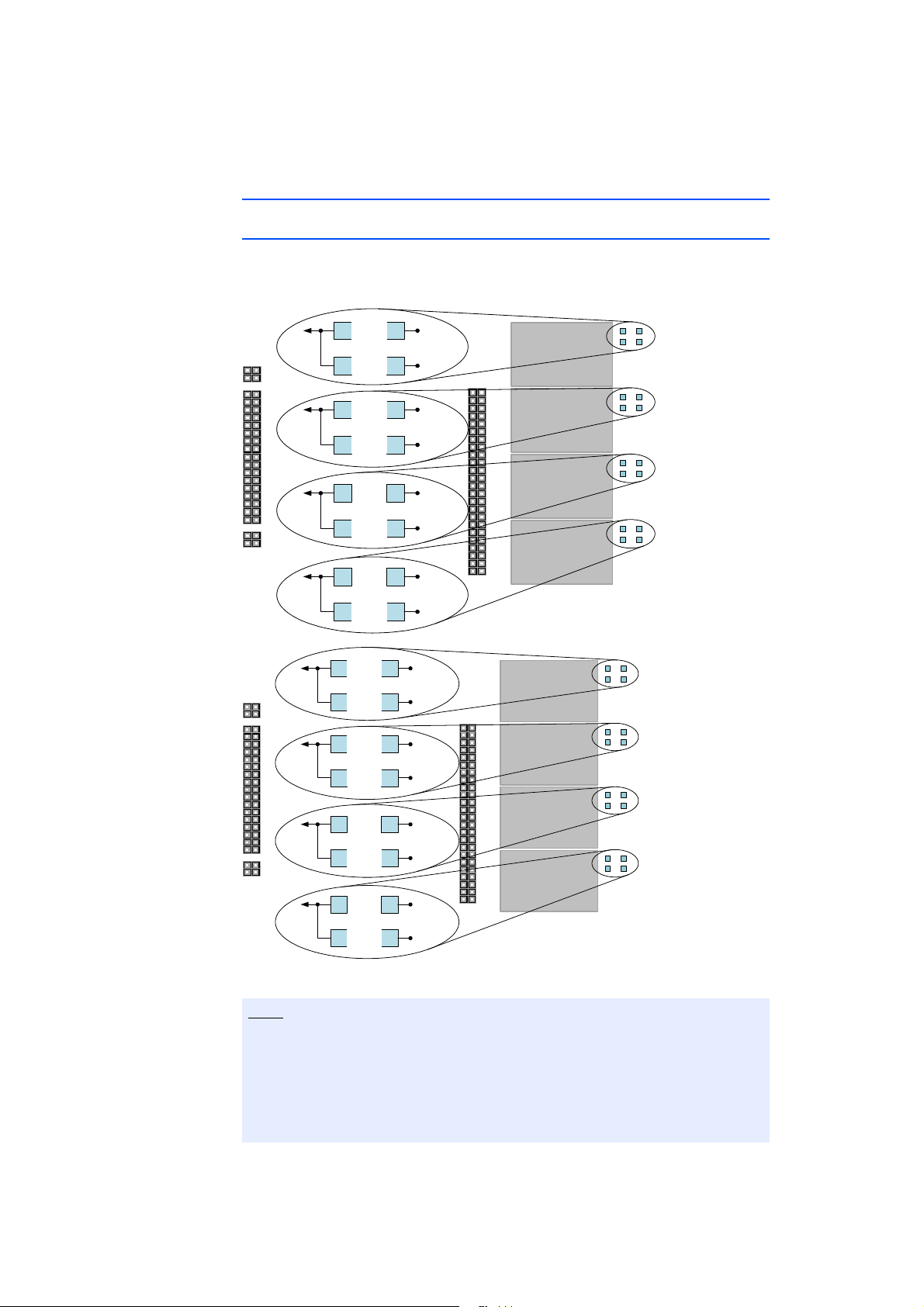
The converters can be supplied from the backplane either with +5 V or +12 V.
The solder bridges next to the DC/DC converters are used to select the supply
voltage.
Fig. 2-4 Position of the Solder Bridges at Slots 1 (Top) and 2 (Bottom)
For system reasons, the plug-in boards and thus the piggybacks have considerably more power available to them via the +12V supply of the backplane
(VCC12) than via the +5V supply (VCC5). The fuses on the ES5352.1 are dimensioned accordingly.
We therefore recommend using a supply voltage of +12V (VCC12) for supplying power to the piggybacks!
ES5352.1 Signal Conditioning Board - User’s Guide22
Page 23
ETAS Features and Functions
Note
Note
CO300
CO301
IC306
IC304
IC303
IC307
CO306
CO307
IC300
IC301
IC302
IC303
R301
R300
R302
R303
R306
R305
R304
R307
R308
R309
R310
R311
R314
R313
R312
R315
Only one solder bridge can be installed because otherwise the +5 V and +12 V
voltages are connected with each other and thus the fuses of the ES5352.1
break the circuit.
2.5.2 Configuring the I2C Addresses
The ES5352.1 supports a total of eight I
2
C bus users which are distinguished by
a 3-bit address. Two addresses are already taken by users on the board and thus
cannot be used. There are therefore six addresses for I
2
C users at the slots.
Address Number Module
0 IC 100 Microchip 24AA64
1
2
3
4 IC101 TI LM95235
5
6
7
2
Tab. 2-3 Occupied Addresses of the I
C Bus
If the addresses are not coded directly on the piggybacks, they can be coded via
two resistor networks on the ES5352.1 Signal Conditioning Board.
Address coding must take place either on the piggyback or on the ES5352.1
- it is not possible to do both at the same time!
To use I
2
C with modules in slot 1, the resistors R300 and R301 must be assem-
bled; in slot 2 the resistors R308 and R309 (see Fig. 2-5 on page 23).
All resistors (0 Ω) are size "0603".
The following figure shows the position of the SMD resistors.
ES5352.1 Signal Conditioning Board - User’s Guide 23
Fig. 2-5 Position of the SMD Resistors
Page 24
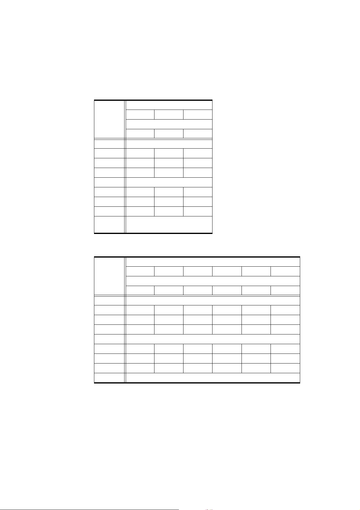
Features and Functions ETAS
The PB1652LAMBDA.1-B piggybacks have a serial I
2
C-EEPROM preconfigured to
address 7. If the address of an EEPROM has to be altered because, for example,
two PB1652LAMBDA.1-B modules are to be assembled on a carrier board, refer
to the following table for details:
Slot 1
R307 R305 R303
Address
Slot 2
R315 R313 R311
0 Assigned
1 xx-
2 x-x
3 x--
4 Assigned
5 -x-
6 --x
7 ---
x=0Ω resistor must be assem-
bled
If there are no 0 Ω resistors on the piggyback which preconfigure address 7, the
address can be determined using the following table:
Slot 1
R307 R305 R303 R306 R304 R302
Address
Slot 2
R315 R313 R311 R314 R312 R310
0 Assigned
1 xx---x
2 x-x-x-
3 x---xx
4 Assigned
5 -x-x-x
6 --xxx-
7 ---xxx
x=0Ω resistor must be assembled
ES5352.1 Signal Conditioning Board - User’s Guide24
Page 25
ETAS Pin Assignment and Connections
12
11
10
9
7
8
6
5
4
3
2
1
hgedfbac
3 Pin Assignment and Connections
This section describes the various connectors of the ES5352.1 Signal Conditioning Board.
• "Backplane Connector (CO200)" on page 25
• "D-Sub62 (CO100)" on page 27
• "Piggyback Connectors" on page 28
• "Connectors on the Board" on page 32
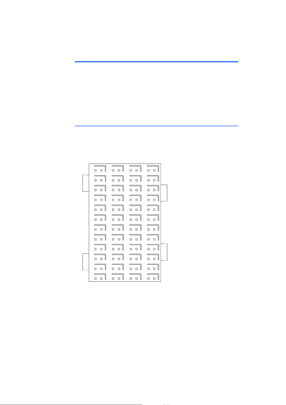
3.1 Backplane Connector (CO200)
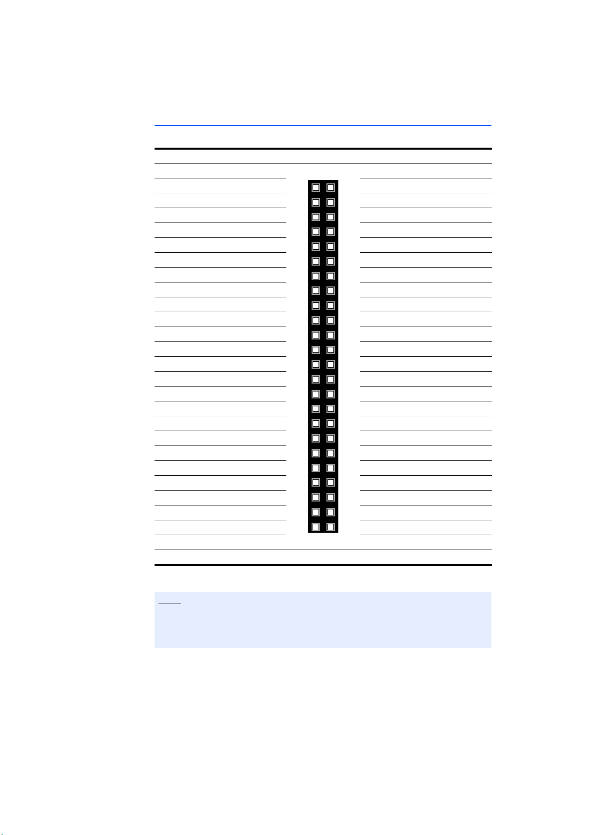
Type: ERNI ERMet ZD Right Angle Female Connector 4 Pair (4-12)
(Part Number 973099)
Mating connector (in ES5300): ERNI ERMet ZD Vertical Male Connector 4 Pair
(4-12) (Part No. 973096)
Fig. 3-1 Connector to the Backplane (Plug-In Side)
The pin assignment is as follows:
ES5352.1 Signal Conditioning Board - User’s Guide 25
Page 26
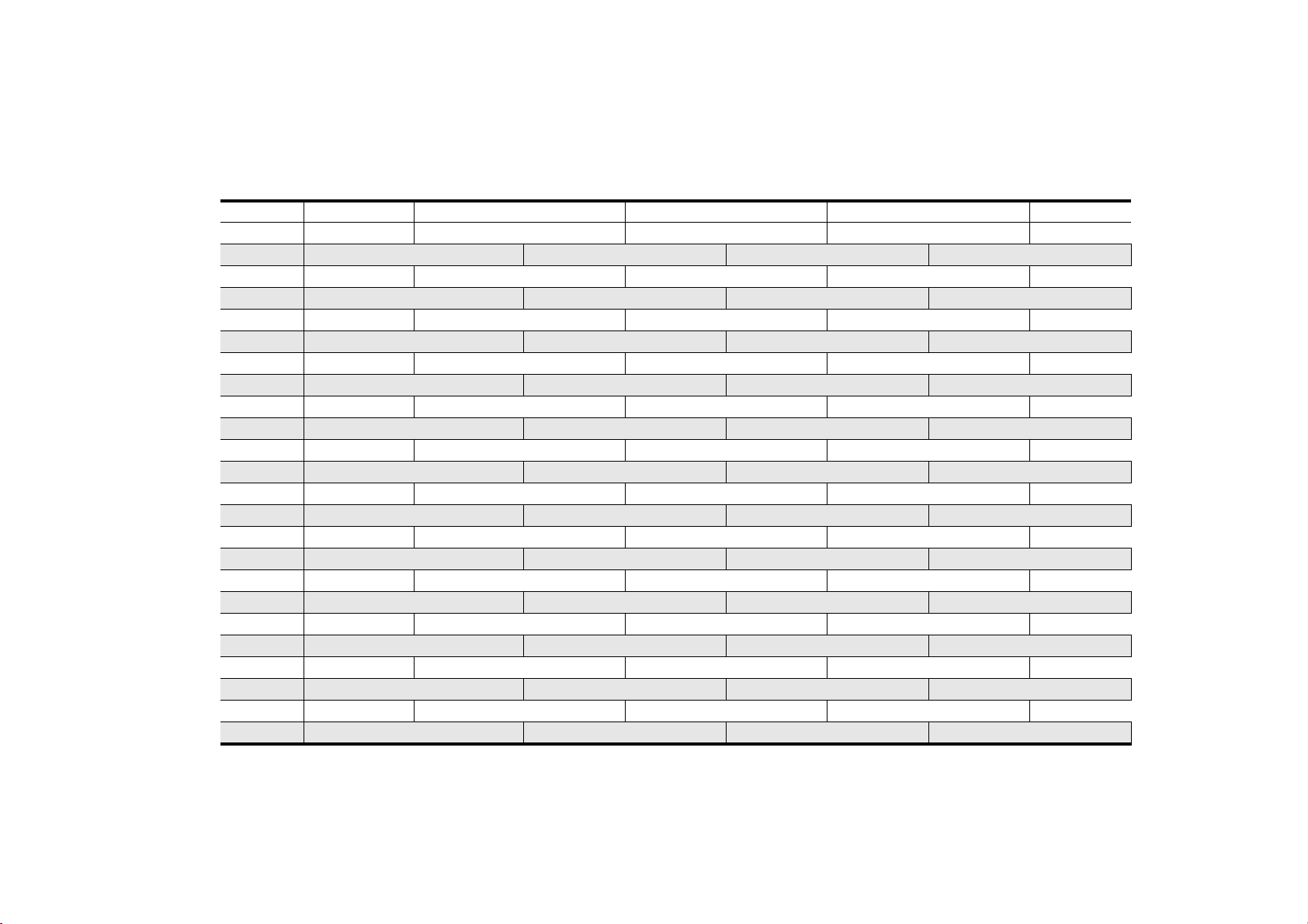
ES5352.1 Signal Conditioning Board - User’s Guide26
Pin Assignment and Connections ETAS
abcdefgh
12 BN_4 BN_5 n.c. n.c. n.c. n.c. n.c. n.c.
12-Shield GND GND GND GND
11 SPI_CS_A_n SPI_CS_B_n n.c. n.c. n.c. n.c. n.c. n.c.
11-Shield GND GND GND GND
10 SPI_CLK SPI_MOSI n.c. n.c. n.c. n.c. n.c. n.c.
10-Shield GND GND GND GND
9 SPI_MISO PCIE_WAKEn n.c. n.c. n.c. n.c. n.c. n.c.
9-Shield GND GND GND GND
8 n.c. n.c. n.c. n.c. n.c. n.c. n.c. n.c.
8-Shield GND GND GND GND
7 n.c. n.c. n.c. n.c. n.c. n.c. n.c. n.c.
7-Shield GND GND GND GND
6 PCIE_JTAG_TDI PCIE_JTAG_TCK n.c. n.c. n.c. n.c. n.c. n.c.
6-Shield GND GND GND GND
5 PCIE_JTAG_TMS PCIE_JTAG_TDO n.c. n.c. n.c. n.c. n.c. n.c.
5-Shield GND GND GND GND
4 BN_2 BN_3 n.c. n.c. n.c. n.c. n.c. n.c.
4-Shield GND GND GND GND
3 BN_0 BN_1 PCIE_SMBCLK PCIE_SMBDAT n.c. n.c. VCC24 VCC24
3-Shield VCC3_3 VCC3_3 VCC3_3 VCC3_3
2 n.c. n.c. n.c. PCIE_PERSTn VCC5 VCC3_3 VSS12 VSS12
2-Shield VCC12 VCC12 VCC12 VCC12
1 VCC12 VCC12 VCC12 VCC12 VCC5 VCC5 VCC3_3 VCC3_3
1-Shield VCC12 VCC12 VCC12 VCC12
Page 27
ETAS Pin Assignment and Connections
Note
1
22
43
21
62
42
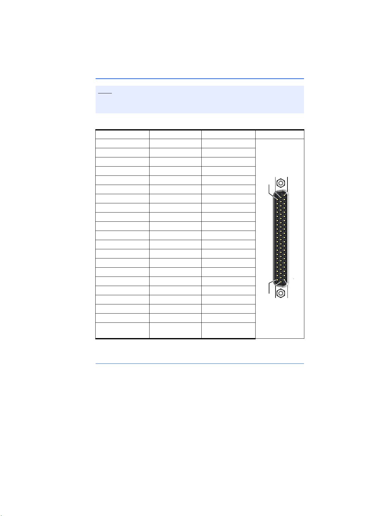
3.2 D-Sub62 (CO100)
For details of the permissible voltages and currents, please refer to the specifications in "Voltages, Currents and Power Consumption" on page 35.
Pin Signal Pin Signal Pin Signal
1 PB1_IN1 22 PB1_IN2 43 PB1_IN3
2 PB1_IN4 23 PB1_IN5 44 PB1_IN6
3 PB1_IN7 24 PB1_IN8 45 PB1_IN9
4 n.c. 25 n.c. 46 PB1_OUT1
5 PB1_OUT2 26 PB1_OUT3 47 PB1_OUT4
6 PB1_OUT5 27 PB1_OUT6 48 PB1_OUT7
7 PB1_OUT8 28 PB1_OUT9 49 PB1_OUT10
8 PB1_OUT11 29 PB1_OUT12 50 PB1_OUT13
9 PB1_OUT14 30 PB1_OUT15 51 n.c.
10 n.c. 31 n.c. 52 n.c.
11 n.c. 32 n.c. 53 n.c.
12 n.c. 33 n.c. 54 n.c.
13 PB2_IN1 34 PB2_IN2 55 PB2_IN3
14 PB2_IN4 35 PB2_IN5 56 PB2_IN6
15 PB2_IN7 36 PB2_IN8 57 PB2_IN9
16 n.c. 37 n.c. 58 PB2_OUT1
17 PB2_OUT2 38 PB2_OUT3 59 PB2_OUT4
18 PB2_OUT5 39 PB2_OUT6 60 PB2_OUT7
19 PB2_OUT8 40 PB2_OUT9 61 PB2_OUT10
20 PB2_OUT11 41 PB2_OUT12 62 PB2_OUT13
21 PB2_OUT14 42 PB2_OUT15 Housing at
protective earth
Tab. 3-1 "CO100" Pin Assignment
Recommended Connectors
The "Conec 163A16629X" connector with "Conec 165X10939X" housing is
recommended for the connection with the D-Sub connector.
ES5352.1 Signal Conditioning Board - User’s Guide 27
Page 28
4
6
8
10
18
2
12
14
16
22
24
26
20
30
28
32
34
3
5
7
9
17
1
11
13
15
21
23
25
19
29
27
31
33
1
22
43
21
62
42
Pin Assignment and Connections ETAS
3.3 Piggyback Connectors
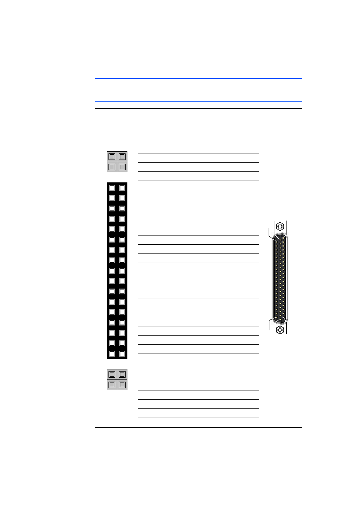
3.3.1 "CO300" Connector (Piggyback 1)
CO300 Signal D-SUB62 (CO100)
1n.c.
2n.c.
3n.c.
4n.c.
5n.c.
6n.c.
7n.c.
8n.c.
9n.c.
10 PB1_IN9 45
11 PB1_IN8
12 PB1_IN7
13 PB1_IN6
14 PB1_IN5
15 PB1_IN4
16 PB1_IN3
17 PB1_IN2
18 PB1_IN1
19 n.c.
20 PB1_OUT15 30
21 PB1_OUT14
22 PB1_OUT13
23 PB1_OUT12
24 PB1_OUT11
25 PB1_OUT10
26 PB1_OUT9
27 PB1_OUT8
28 PB1_OUT7
29 PB1_OUT6
30 PB1_OUT5
31 PB1_OUT4
32 PB1_OUT3
33 PB1_OUT2
34 PB1_OUT1
Tab. 3-2 Connections from "CO300" to SUB-D62 (CO100)
24
3
44
23
2
43
22
1
9
50
29
8
49
28
7
48
27
6
47
26
5
46
ES5352.1 Signal Conditioning Board - User’s Guide28
Page 29
Note
3
5
7
9
17
1
11
13
15
21
23
25
19
29
27
31
33
35
37
39
41
43
45
47
4
6
8
10
18
2
12
14
16
22
24
26
20
30
28
32
34
36
38
40
42
44
46
48
ETAS Pin Assignment and Connections
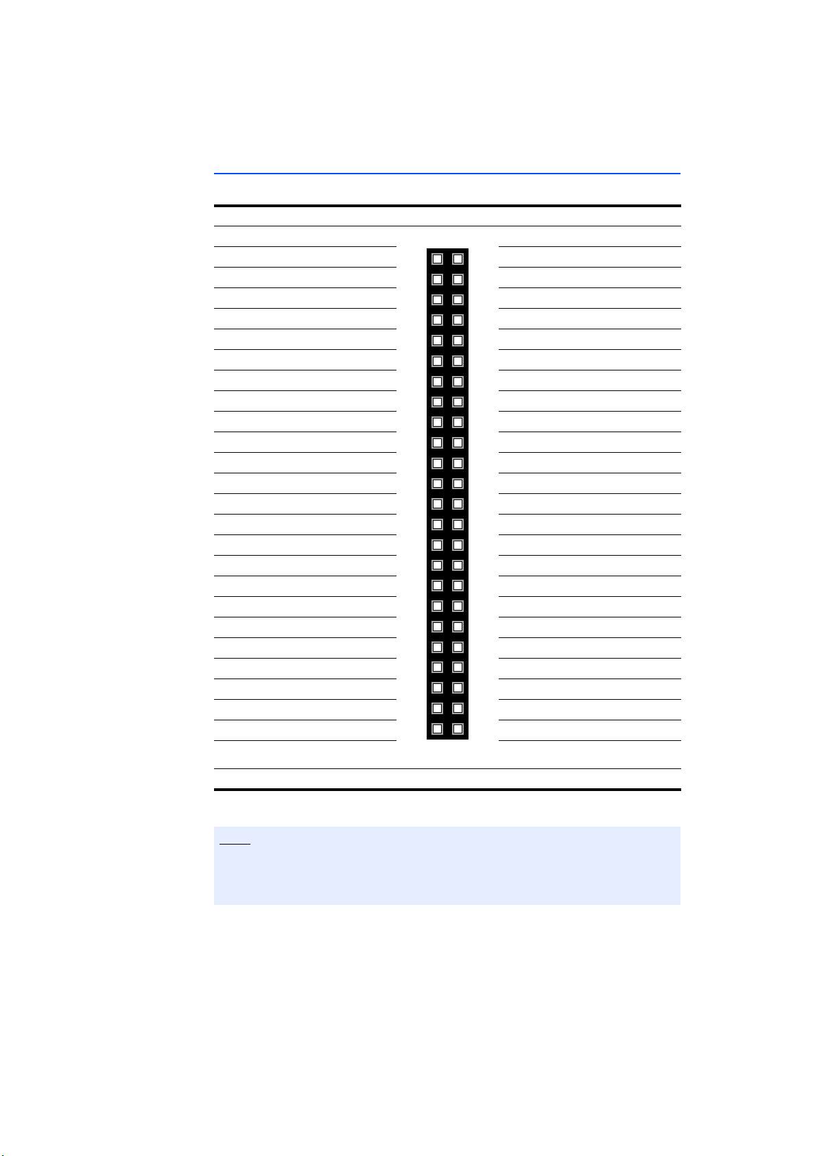
3.3.2 "CO301" Connector (Piggyback 1)
Signal CO301 Signal
PB1_DC1 VDD 2 1 PB1_DC1 GND
PB1_DC1 VSS 4 3 PB1_DC1 GND
PB1_DC2 VDD 6 5 PB1_DC2 GND
PB1_DC2 VSS 8 7 PB1_DC2 GND
PB1_DC3 VDD 10 9 PB1_DC3 GND
PB1_DC3 VSS 12 11 PB1_DC3 GND
PB1_DC4 VDD 14 13 PB1_DC4 GND
PB1_DC4 VSS 16 15 PB1_DC4 GND
Reserved 18 17 n.c.
Reserved 20 19 Reserved
/SYSRESET * 22 21 Reserved
VSS12 * 24 23 GND *
VCC12 * 26 25 GND *
VCC12 * 28 27 GND *
VCC5 * 30 29 GND *
VCC5 * 32 31 GND *
VCC5 * 34 33 GND *
2
C CLK * 36 35 I2C DAT
I
2
C A0 * 38 37 GND *
I
2
C A2 * 40 39 I2C A1 *
I
n.c. 42 41 n.c.
n.c. 44 43 n.c.
VCC 3_3 * 46 45 n.c.
GND * 48 47 GND *
* From the backplane
Tab. 3-3 Pin Assignment of the "CO301" Connector
To avoid interference in the system, the backplane ground (GND) and the galvanically isolated piggyback grounds (PBx_DCn GND, x = slot 1 or 2,
n = 1,2,3,4) should not be connected!
ES5352.1 Signal Conditioning Board - User’s Guide 29
Page 30
4
6
8
10
18
2
12
14
16
22
24
26
20
30
28
32
34
3
5
7
9
17
1
11
13
15
21
23
25
19
29
27
31
33
1
22
43
21
62
42
Pin Assignment and Connections ETAS
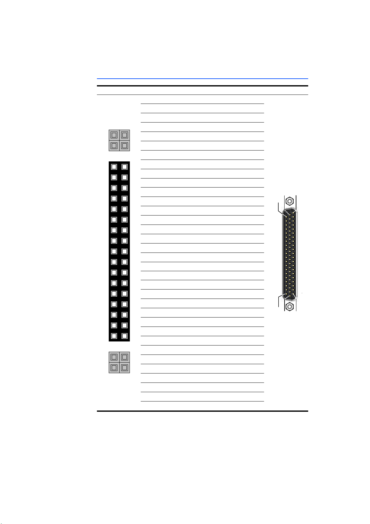
3.3.3 "CO306" Connector (Piggyback 2)
CO306 Signal D-SUB62 (CO100)
1n.c.
2n.c.
3n.c.
4n.c.
5n.c.
6n.c.
7n.c.
8n.c.
9n.c.
10 PB2_IN9 57
11 PB2_IN8
12 PB2_IN7
13 PB2_IN6
14 PB2_IN5
15 PB2_IN4
16 PB2_IN3
17 PB2_IN2
18 PB2_IN1
19 n.c.
20 PB2_OUT15 42
21 PB2_OUT14
22 PB2_OUT13
23 PB2_OUT12
24 PB2_OUT11
25 PB2_OUT10
26 PB2_OUT9
27 PB2_OUT8
28 PB2_OUT7
29 PB2_OUT6
30 PB2_OUT5
31 PB2_OUT4
32 PB2_OUT3
33 PB2_OUT2
34 PB2_OUT1
Tab. 3-4 Connections from "CO306" to SUB-D62 (CO100)
36
15
56
35
14
55
34
13
21
62
41
20
61
40
19
60
39
18
59
38
17
58
ES5352.1 Signal Conditioning Board - User’s Guide30
Page 31
Note
3
5
7
9
17
1
11
13
15
21
23
25
19
29
27
31
33
35
37
39
41
43
45
47
4
6
8
10
18
2
12
14
16
22
24
26
20
30
28
32
34
36
38
40
42
44
46
48
ETAS Pin Assignment and Connections
3.3.4 "CO307" Connector (Piggyback 2)
Signal CO307 Signal
PB2_DC1 VDD 2 1 PB2_DC1 GND
PB2_DC1 VSS 4 3 PB2_DC1 GND
PB2_DC2 VDD 6 5 PB2_DC2 GND
PB2_DC2 VSS 8 7 PB2_DC2 GND
PB2_DC3 VDD 10 9 PB2_DC3 GND
PB2_DC3 VSS 12 11 PB2_DC3 GND
PB2_DC4 VDD 14 13 PB2_DC4 GND
PB2_DC4 VSS 16 15 PB2_DC4 GND
Reserved 18 17 n.c.
Reserved 20 19 Reserved
/SYSRESET 22 21 Reserved
VSS12 * 24 23 GND *
VCC12 * 26 25 GND *
VCC12 * 28 27 GND *
VCC5 * 30 29 GND *
VCC5 * 32 31 GND *
VCC5 * 34 33 GND *
2
C CLK 36 35 I2C DAT
I
2
C A0 38 37 GND *
I
2
C A2 40 39 I2C A1
I
n.c. 42 41 n.c.
n.c. 44 43 n.c.
VCC 3_3 46 45 n.c.
GND * 48 47 GND *
* From the backplane
Tab. 3-5 Pin Assignment of the "CO307" Connector
To avoid interference in the system, the backplane ground (GND) and the galvanically isolated piggyback grounds (PBx_DCn GND, x = slot 1 or 2,
n = 1,2,3,4) should not be connected!
ES5352.1 Signal Conditioning Board - User’s Guide 31
Page 32
Pin Assignment and Connections ETAS
3.4 Connectors on the Board
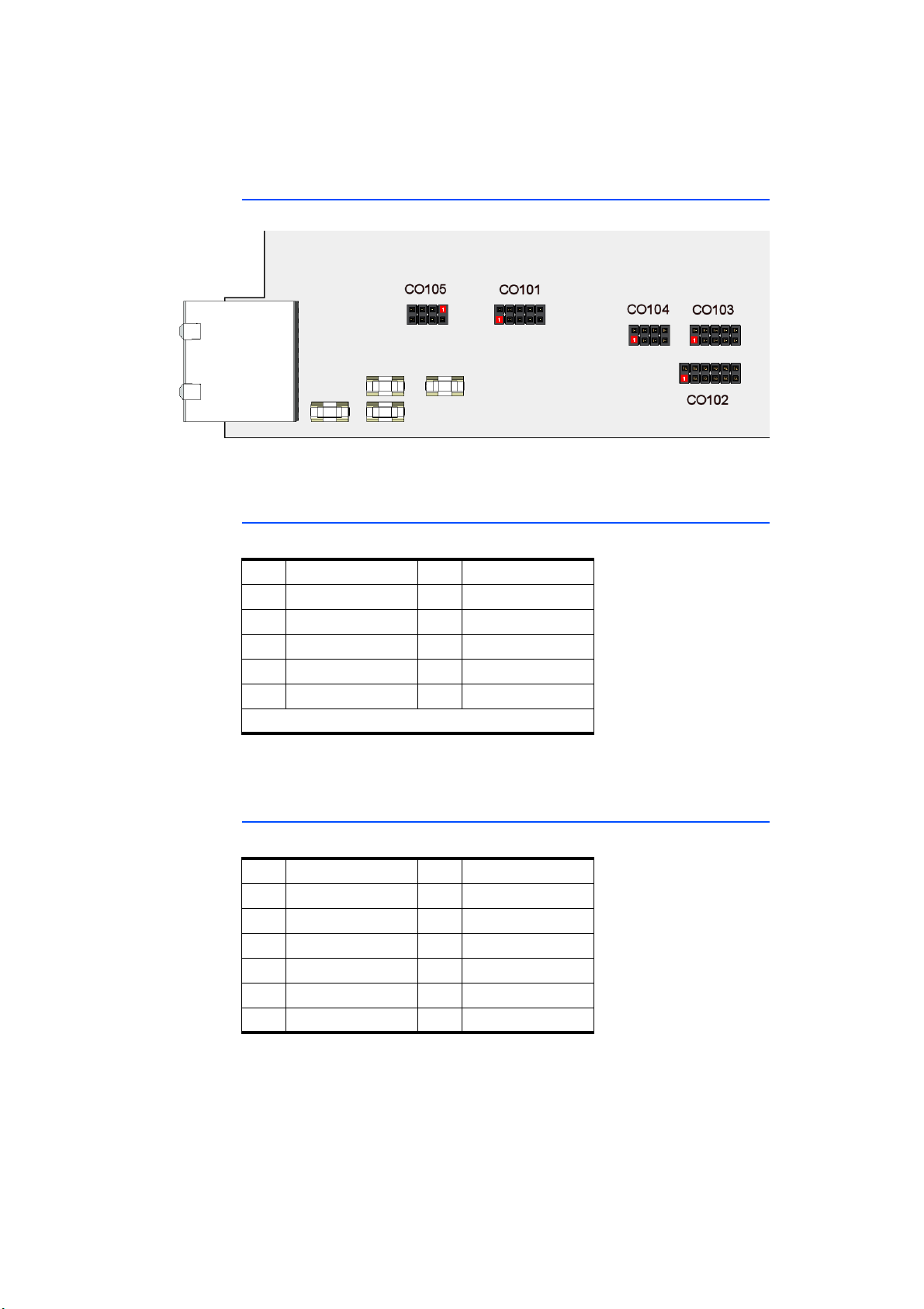
Fig. 3-2 Connectors on the Board (Red = Pin 1)
The connectors are designed for 50 cycles of operation.
3.4.1 C0101
This is where the backplane voltages are available.
Pin Signal Pin Signal
1VCC24 *2 GND
3 VCC12 4 GND
5 VCC5 6 GND
7 VCC3_3 8 GND
9 VSS12 10 GND
* If available on the ES5300 backplane
Tab. 3-6 "CO101" Pin Assignment
3.4.2 C0102
This is where the battery node control signals from the backplane are available.
Pin Signal Pin Signal
1BN_B_02 GND
3BN_B_14 GND
5BN_B_26 GND
7BN_B_38 GND
9 BN_B_4 10 GND
11 BN_B_5 12 GND
Tab. 3-7 "CO102" Pin Assignment
The "BN_B_n" signals are buffered by the driver modules TI 74LVTH16245. Each
signal has a series resistance of 43.2 Ohm.
ES5352.1 Signal Conditioning Board - User’s Guide32
Page 33
ETAS Pin Assignment and Connections
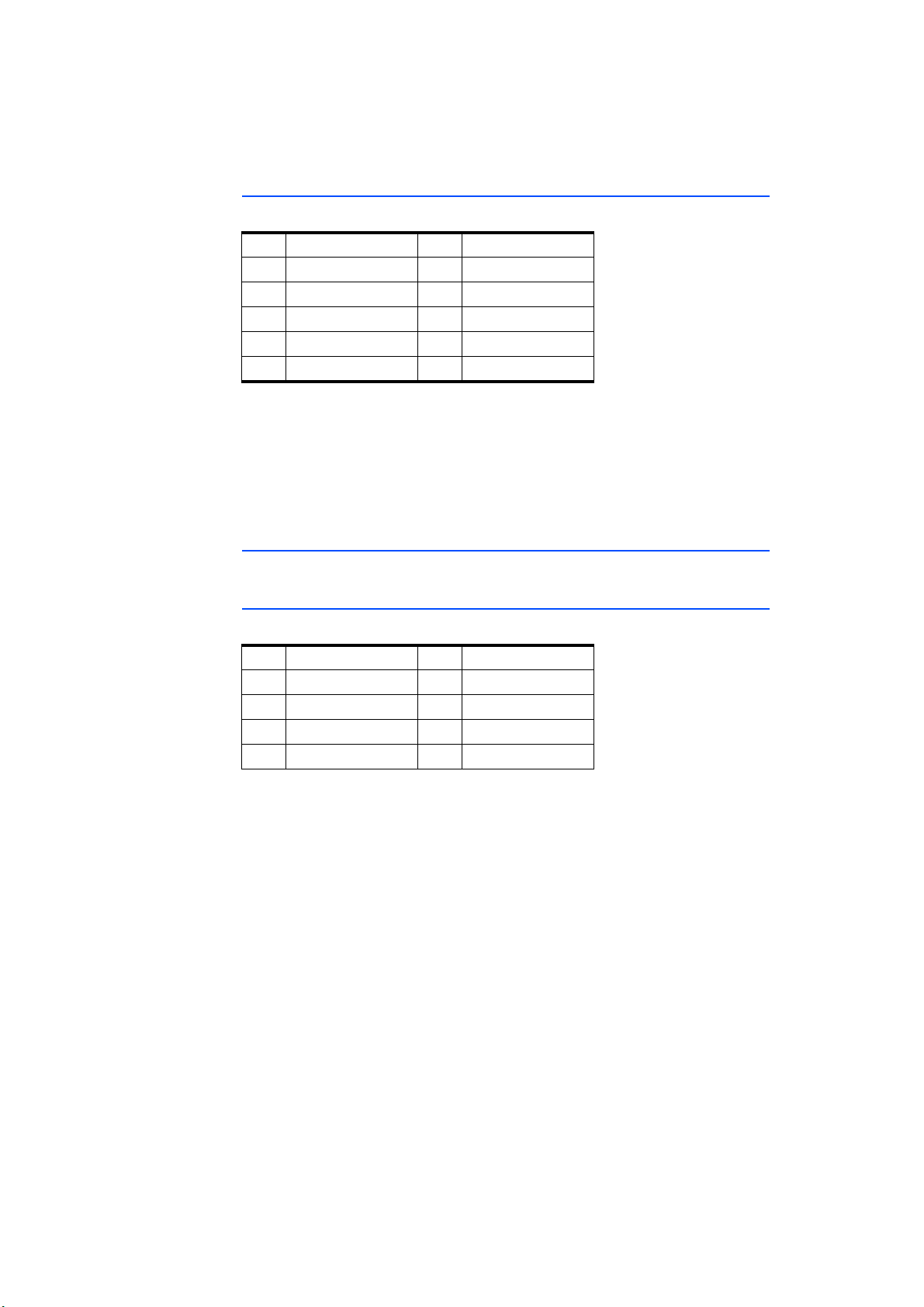
3.4.3 C0103
This is where the SPI signals from the backplane are available.
Pin Signal Pin Signal
1 SPI_CLK_B 2 GND
3 SPI_MOSI_B 4 GND
5 SPI_MISO_B 6 GND
7 /SPI_CS_A_B 8 GND
9 /SPI_CS_B_B 10 GND
Tab. 3-8 "CO103" Pin Assignment
The SPI signals are buffered by driver modules – coming from the backplane, the
TI 74LVTH16245 is used, driving toward the backplane the TI 74AVC2T245. For
more information, refer to the data sheets of the relevant driver modules.
The signals "SPI_CLK_B" and "SPI_MISO_B" both have a series resistance of
43.2 Ohm.
3.4.4 C0104
For internal use only.
3.4.5 C0105
This is where the I
Pin Signal Pin Signal
1 /PCIE_PERST 2 GND
3 /PCIE_WAKE 4 GND
5 PCIE_SMBCLK 6 GND
7 PCIE_SMBDAT 8 GND
Tab. 3-9 "CO105" Pin Assignment
2
The I
CO301 and CO307 connectors go directly to the backplane and to the bus users
on the boards.
2
C signals from the backplane are available.
C signals "PCIE_SMBCLK" and "PCIE_SMBDAT" available at the CO105,
ES5352.1 Signal Conditioning Board - User’s Guide 33
Page 34

Pin Assignment and Connections ETAS
ES5352.1 Signal Conditioning Board - User’s Guide34
Page 35
ETAS Technical Data and Norms
4 Technical Data and Norms
This chapter contains the technical data on the ES5352.1 Signal Conditioning
Board. In addition, fulfilled standards and norms are listed.
4.1 Technical Data
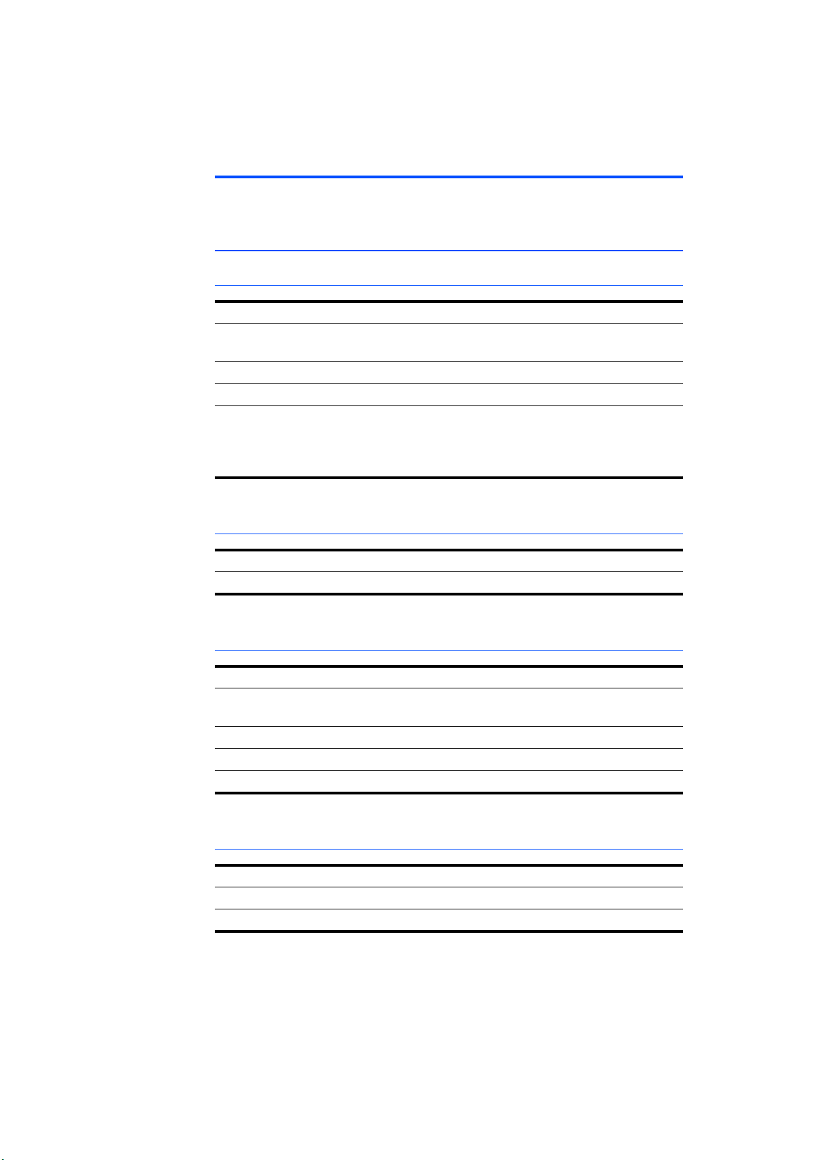
Voltages, Currents and Power Consumption
Maximum voltage at inputs and outputs (CO100) 60 V
Maximum current per individual contact of the input/output
connector (CO100)
Maximum total current over the input/output connector (CO100) 5 A
Maximum permissible power consumption per DC/DC converter 3 W
Maximum permissible power consumption from backplane
12 V
5V
3.3 V
1A
25 W
4W
8W
Storage Conditions
Ambient temperature –20 °C to +85 °C (–4 °F to +185 °F)
Relative humidity 0 to 95% (non-condensing)
Ambient Conditions
Environment Use only inside enclosed and dry rooms
Temperature during operation
Relative humidity 0 to 95% (non-condensing)
Max. contamination level 2
Operating altitude -200 m to 2000 m / 6500 ft above sea level
Physical Dimensions
Height 4 U
Width 5 HP
Weight 0,5 kg
+5 °C to +40 °C (+41 °F to +104 °F)
ES5352.1 Signal Conditioning Board - User’s Guide 35
Page 36
Technical Data and Norms ETAS
WARNING!
4.2 Fulfilled Standards and Norms
The ES5352.1 Signal Conditioning Board complies with the following standards
and norms:
Standard Testing
EN 61326 Electrical equipment for measurement, control and labora-
tory use
EMC requirements
EN 61000-6-2 Interference immunity (industrial environment)
EN 61000-6-4 Emissions (industrial environments)
The board is only designed for use in industrial environments compliant with IEC
61326-1. Avoid any possible radio interference when using the module outside
industrial environments with additional shielding measures!
This is class A equipment. This equipment can cause radio interference in residential areas. Should that be the case, the operator may
be requested to institute reasonable measures
ES5352.1 Signal Conditioning Board - User’s Guide36
Page 37

ETAS Ordering Information
5 Ordering Information
This chapter features the ordering information for the ES5352.1 Signal Conditioning Board as follows:
Order Name Short Name Order Number
Carrier Board for Signal Conditioning
Circuits
Scope of Supply
Carrier Board for Signal Conditioning
Circuits
ES5352.1 F-00K-109-679
ES5352.1 Signal Conditioning Board - User’s Guide 37
Page 38

Ordering Information ETAS
ES5352.1 Signal Conditioning Board - User’s Guide38
Page 39

ETAS ETAS Contact Addresses
6 ETAS Contact Addresses
ETAS HQ
ETAS GmbH
Borsigstraße 24 Phone: +49 711 3423-0
70469 Stuttgart Fax: +49 711 3423-2106
Germany WWW: www.etas.com
ETAS Subsidiaries and Technical Support
For details of your local sales office as well as your local technical support team
and product hotlines, take a look at the ETAS website:
ETAS subsidiaries WWW: www.etas.com/en/contact.php
ETAS technical support WWW: www.etas.com/en/hotlines.php
ES5352.1 Signal Conditioning Board - User’s Guide 39
Page 40

ETAS Contact Addresses ETAS
ES5352.1 Signal Conditioning Board - User’s Guide40
Page 41

ETAS Index
Index
A
accident prevention
Assembling
in the ES5300.1-A Housing
in the ES5300.1-B Housing
piggybacks
B
Block diagram
C
CE Declaration of Conformity
Connecting devices
connections
Connectors
backplane connectors
CO300
CO301
CO306
CO307
D
DC/DC converters
configuring the input voltage
Declarable Substances
Devices
Connecting
E
ETAS Contact Addresses
25
28
29
30
31
8
20
6
12
25
14
12
39
20
20
13
22
F
Features
Fuses
I
I2C addresses
Identifications on the product
Improper use
K
KC
KC Marking
O
Ordering Information
P
Ports
Power supply
Q
Qualification, required
R
Recycling
RoHS conformity
6
18
configuration
8
14
14
25
for piggybacks
14
China
13
European Union
23
37
17
8
13
13
ES5352.1 Signal Conditioning Board - User’s Guide 41
Page 42

Index ETAS
S
Safety instructions
basic
8
Safety instructions, labeling of
safety precautions
Standards and norms
T
Technical data
U
Use, intended
W
Waste Electrical and Electronic Equip-
ment
WEEE take-back system
8
36
35
9
14
14
8
ES5352.1 Signal Conditioning Board - User’s Guide42
 Loading...