

Page 1

ES415.1
High Definition A/D Module with Sensor Supply
User’s Guide
Page 2

Copyright
The data in this document may not be altered or amended without special notification from ETAS GmbH. ETAS GmbH undertakes no further obligation in relation to this document. The software described in it can only be used if the
customer is in possession of a general license agreement or single license. Using
and copying is only allowed in concurrence with the specifications stipulated in
the contract.
Under no circumstances may any part of this document be copied, reproduced,
transmitted, stored in a retrieval system or translated into another language
without the express written permission of ETAS GmbH.
© Copyright 2018 ETAS GmbH, Stuttgart
The names and designations used in this document are trademarks or brands
belonging to the respective owners.
ES415.1 - User’s Guide R08 EN - 04.2018
2
Page 3

ETAS Contents
Contents
1 About this Manual . . . . . . . . . . . . . . . . . . . . . . . . . . . . . . . . . . . . . . . . . . . . . . . . . 7
1.1 Identification of Safety Notices . . . . . . . . . . . . . . . . . . . . . . . . . . . . . . . . . . . 7
1.2 Presentation of Information . . . . . . . . . . . . . . . . . . . . . . . . . . . . . . . . . . . . . 8
1.3 Scope of Supply . . . . . . . . . . . . . . . . . . . . . . . . . . . . . . . . . . . . . . . . . . . . . . 8
1.4 Additional Information . . . . . . . . . . . . . . . . . . . . . . . . . . . . . . . . . . . . . . . . . 8
2 Basic Safety Notices . . . . . . . . . . . . . . . . . . . . . . . . . . . . . . . . . . . . . . . . . . . . . . . . 9
2.1 General Safety Information . . . . . . . . . . . . . . . . . . . . . . . . . . . . . . . . . . . . . . 9
2.2 Requirements for Users and Duties for Operators . . . . . . . . . . . . . . . . . . . . . 9
2.3 Intended Use . . . . . . . . . . . . . . . . . . . . . . . . . . . . . . . . . . . . . . . . . . . . . . . . 9
3 ES400 Product Family . . . . . . . . . . . . . . . . . . . . . . . . . . . . . . . . . . . . . . . . . . . . . . 14
3.1 Wiring Concepts in Test Vehicles . . . . . . . . . . . . . . . . . . . . . . . . . . . . . . . . 14
3.2 Features of the ES400 Line . . . . . . . . . . . . . . . . . . . . . . . . . . . . . . . . . . . . . 15
3.2.1 Advantages of the Decentral Wiring Concept . . . . . . . . . . . . . . . . 15
3.2.2 Further Features . . . . . . . . . . . . . . . . . . . . . . . . . . . . . . . . . . . . . . 15
3.3 Housing . . . . . . . . . . . . . . . . . . . . . . . . . . . . . . . . . . . . . . . . . . . . . . . . . . . 16
3.4 Ports . . . . . . . . . . . . . . . . . . . . . . . . . . . . . . . . . . . . . . . . . . . . . . . . . . . . . . 17
3.4.1 “Sensor” Port . . . . . . . . . . . . . . . . . . . . . . . . . . . . . . . . . . . . . . . . 17
3.4.2 Daisy Chain Ports (“IN”, “OUT”) . . . . . . . . . . . . . . . . . . . . . . . . . . 17
3.5 LED . . . . . . . . . . . . . . . . . . . . . . . . . . . . . . . . . . . . . . . . . . . . . . . . . . . . . . . 18
3.5.1 Operational State . . . . . . . . . . . . . . . . . . . . . . . . . . . . . . . . . . . . . 18
3.5.2 Service State . . . . . . . . . . . . . . . . . . . . . . . . . . . . . . . . . . . . . . . . . 18
3.5.3 Functional State. . . . . . . . . . . . . . . . . . . . . . . . . . . . . . . . . . . . . . . 18
4 Hardware Description . . . . . . . . . . . . . . . . . . . . . . . . . . . . . . . . . . . . . . . . . . . . . . 19
4.1 Features of the ES415.1 . . . . . . . . . . . . . . . . . . . . . . . . . . . . . . . . . . . . . . . 19
4.2 Block Diagram . . . . . . . . . . . . . . . . . . . . . . . . . . . . . . . . . . . . . . . . . . . . . . 20
4.3 Sensor Channels . . . . . . . . . . . . . . . . . . . . . . . . . . . . . . . . . . . . . . . . . . . . . 21
4.3.1 Signal Processing and Filters . . . . . . . . . . . . . . . . . . . . . . . . . . . . . 21
ES415.1 - User’s Guide 3
Page 4

Contents ETAS
4.3.2 Amplifier and analog Filter. . . . . . . . . . . . . . . . . . . . . . . . . . . . . . . 21
4.3.3 A/D Converter . . . . . . . . . . . . . . . . . . . . . . . . . . . . . . . . . . . . . . . . 21
4.3.4 Digital Filter . . . . . . . . . . . . . . . . . . . . . . . . . . . . . . . . . . . . . . . . . . 22
4.3.5 Maximum Input and Common-Mode Voltages . . . . . . . . . . . . . . . 23
4.3.6 Galvanically Isolation . . . . . . . . . . . . . . . . . . . . . . . . . . . . . . . . . . . 24
4.3.7 Sensor Supply . . . . . . . . . . . . . . . . . . . . . . . . . . . . . . . . . . . . . . . . 25
4.4 Data Transfer . . . . . . . . . . . . . . . . . . . . . . . . . . . . . . . . . . . . . . . . . . . . . . . 26
4.4.1 Communication Protocols . . . . . . . . . . . . . . . . . . . . . . . . . . . . . . . 26
4.4.2 Realization . . . . . . . . . . . . . . . . . . . . . . . . . . . . . . . . . . . . . . . . . . 27
4.4.3 Examples . . . . . . . . . . . . . . . . . . . . . . . . . . . . . . . . . . . . . . . . . . . . 29
4.5 Power Supply . . . . . . . . . . . . . . . . . . . . . . . . . . . . . . . . . . . . . . . . . . . . . . . 31
4.5.1 Supply Voltage . . . . . . . . . . . . . . . . . . . . . . . . . . . . . . . . . . . . . . . 31
4.5.2 Supplying the ES400 Modules via the Connecting Line . . . . . . . . . 31
4.5.3 Additional Supply of the ES400 Modules via a Y-Boost Cable . . . . 31
4.6 Configuration . . . . . . . . . . . . . . . . . . . . . . . . . . . . . . . . . . . . . . . . . . . . . . . 33
4.7 Tool Integration . . . . . . . . . . . . . . . . . . . . . . . . . . . . . . . . . . . . . . . . . . . . . 33
4.8 Firmware Update . . . . . . . . . . . . . . . . . . . . . . . . . . . . . . . . . . . . . . . . . . . . 33
4.9 Calibration . . . . . . . . . . . . . . . . . . . . . . . . . . . . . . . . . . . . . . . . . . . . . . . . . 33
5 Getting Started . . . . . . . . . . . . . . . . . . . . . . . . . . . . . . . . . . . . . . . . . . . . . . . . . . . 34
5.1 General Installation Recommendations . . . . . . . . . . . . . . . . . . . . . . . . . . . . 34
5.1.1 Assembly Environment and Components for Attaching the Module 34
5.1.2 Potential Equalization in the Vehicle and Mounting the Modules . 34
5.1.3 Guarantee of Features as defined by IP67 . . . . . . . . . . . . . . . . . . . 35
5.2 Assembly . . . . . . . . . . . . . . . . . . . . . . . . . . . . . . . . . . . . . . . . . . . . . . . . . . 36
5.2.1 How to Connect and Attach ES400 Modules . . . . . . . . . . . . . . . . . 36
5.2.2 Connecting Several ES400 Modules Mechanically . . . . . . . . . . . . . 37
5.2.3 Attaching ES400 Modules to Other Components Using the Integrated
Assembly Elements . . . . . . . . . . . . . . . . . . . . . . . . . . . . . . . . . . . . 39
5.2.4 Attaching ES400 Modules on DIN Rails with the Integrated Assembly
Elements . . . . . . . . . . . . . . . . . . . . . . . . . . . . . . . . . . . . . . . . . . . . 42
5.2.5 Attaching ES400 Modules to Other Components with Screws . . . . 44
5.2.6 Attaching ES400 Modules on DIN Rails using Screws . . . . . . . . . . . 46
5.2.7 Attaching ES400 Modules to Other Components Using Cable Fasten-
ers. . . . . . . . . . . . . . . . . . . . . . . . . . . . . . . . . . . . . . . . . . . . . . . . . 49
5.3 Drilling Template . . . . . . . . . . . . . . . . . . . . . . . . . . . . . . . . . . . . . . . . . . . . 50
5.4 Applications . . . . . . . . . . . . . . . . . . . . . . . . . . . . . . . . . . . . . . . . . . . . . . . . 51
5.4.1 General . . . . . . . . . . . . . . . . . . . . . . . . . . . . . . . . . . . . . . . . . . . . . 51
5.4.2 ES415.1 with additional ETAS Modules (MC Application). . . . . . . . 51
5.4.3 ES415.1 with additional ETAS Modules (Rapid Prototyping Application)
52
5.5 Wiring Examples . . . . . . . . . . . . . . . . . . . . . . . . . . . . . . . . . . . . . . . . . . . . . 53
5.5.1 ES400 Modules with additional ETAS Modules (Measurement and Cal-
ibration) . . . . . . . . . . . . . . . . . . . . . . . . . . . . . . . . . . . . . . . . . . . . 53
5.5.2 ES400 Modules with additional ETAS Modules and Drive Recorder
(Measurement and Calibration) . . . . . . . . . . . . . . . . . . . . . . . . . . . 54
5.5.3 ES400 Modules with ES910.3 (Rapid Prototyping) . . . . . . . . . . . . . 55
5.5.4 ES400 Modules with ES910.3 and Drive Recorder (Rapid Prototyping)
56
ES415.1 - User’s Guide4
Page 5

ETAS Contents
5.5.5 ES400 Modules with ETAS RTPRO-PC (Rapid Prototyping) . . . . . . . 57
5.6 Wiring . . . . . . . . . . . . . . . . . . . . . . . . . . . . . . . . . . . . . . . . . . . . . . . . . . . . 58
5.6.1 “Sensor” Port . . . . . . . . . . . . . . . . . . . . . . . . . . . . . . . . . . . . . . . . 58
5.6.2 Daisy Chain Ports (“IN”, “OUT”) . . . . . . . . . . . . . . . . . . . . . . . . . . 59
6 Troubleshooting Problems. . . . . . . . . . . . . . . . . . . . . . . . . . . . . . . . . . . . . . . . . . . 61
6.1 LED Displays . . . . . . . . . . . . . . . . . . . . . . . . . . . . . . . . . . . . . . . . . . . . . . . . 61
6.2 Troubleshooting ES415.1 Problems . . . . . . . . . . . . . . . . . . . . . . . . . . . . . . . 61
6.3 Problems and Solutions . . . . . . . . . . . . . . . . . . . . . . . . . . . . . . . . . . . . . . . . 64
6.3.1 Network Adapter Cannot Be Selected via Network Manager . . . . . 64
6.3.2 Search for Ethernet Hardware Fails . . . . . . . . . . . . . . . . . . . . . . . . 65
6.3.3 Personal Firewall Blocks Communication . . . . . . . . . . . . . . . . . . . . 67
7 Technical Data . . . . . . . . . . . . . . . . . . . . . . . . . . . . . . . . . . . . . . . . . . . . . . . . . . . 70
7.1 General Data . . . . . . . . . . . . . . . . . . . . . . . . . . . . . . . . . . . . . . . . . . . . . . . 70
7.1.1 Product labeling . . . . . . . . . . . . . . . . . . . . . . . . . . . . . . . . . . . . . . 70
7.1.2 Standards and Norms . . . . . . . . . . . . . . . . . . . . . . . . . . . . . . . . . . 71
7.1.3 Environmental Conditions . . . . . . . . . . . . . . . . . . . . . . . . . . . . . . 73
7.1.4 Maintenance the Product . . . . . . . . . . . . . . . . . . . . . . . . . . . . . . . 73
7.1.5 Cleaning the product. . . . . . . . . . . . . . . . . . . . . . . . . . . . . . . . . . . 73
7.1.6 Mechanical Data . . . . . . . . . . . . . . . . . . . . . . . . . . . . . . . . . . . . . . 73
7.1.7 Modules in one chain . . . . . . . . . . . . . . . . . . . . . . . . . . . . . . . . . . 73
7.2 RoHS conformity . . . . . . . . . . . . . . . . . . . . . . . . . . . . . . . . . . . . . . . . . . . . . 74
7.2.1 European Union . . . . . . . . . . . . . . . . . . . . . . . . . . . . . . . . . . . . . . 74
7.2.2 China . . . . . . . . . . . . . . . . . . . . . . . . . . . . . . . . . . . . . . . . . . . . . . 74
7.3 CE marking . . . . . . . . . . . . . . . . . . . . . . . . . . . . . . . . . . . . . . . . . . . . . . . . . 74
7.4 Product return and recycling . . . . . . . . . . . . . . . . . . . . . . . . . . . . . . . . . . . . 74
7.5 Declarable Substances . . . . . . . . . . . . . . . . . . . . . . . . . . . . . . . . . . . . . . . . 75
7.6 Use of Open Source software . . . . . . . . . . . . . . . . . . . . . . . . . . . . . . . . . . . 75
7.7 System Requirements . . . . . . . . . . . . . . . . . . . . . . . . . . . . . . . . . . . . . . . . . 75
7.7.1 Hardware . . . . . . . . . . . . . . . . . . . . . . . . . . . . . . . . . . . . . . . . . . . 75
7.7.2 Software . . . . . . . . . . . . . . . . . . . . . . . . . . . . . . . . . . . . . . . . . . . . 76
7.8 Electrical Data . . . . . . . . . . . . . . . . . . . . . . . . . . . . . . . . . . . . . . . . . . . . . . . 77
7.8.1 Host Interface ("IN" Connection) . . . . . . . . . . . . . . . . . . . . . . . . . 77
7.8.2 Power Supply . . . . . . . . . . . . . . . . . . . . . . . . . . . . . . . . . . . . . . . . 78
7.8.3 Sensor Power Supply . . . . . . . . . . . . . . . . . . . . . . . . . . . . . . . . . . . 78
7.8.4 Sensor Inputs . . . . . . . . . . . . . . . . . . . . . . . . . . . . . . . . . . . . . . . . 79
7.8.5 Signal Processing . . . . . . . . . . . . . . . . . . . . . . . . . . . . . . . . . . . . . 81
7.9 Pin Assignment . . . . . . . . . . . . . . . . . . . . . . . . . . . . . . . . . . . . . . . . . . . . . . 82
7.9.1 “IN” Connector. . . . . . . . . . . . . . . . . . . . . . . . . . . . . . . . . . . . . . . 82
7.9.2 “OUT” Connector . . . . . . . . . . . . . . . . . . . . . . . . . . . . . . . . . . . . . 83
7.9.3 “Sensor” Connector . . . . . . . . . . . . . . . . . . . . . . . . . . . . . . . . . . . 84
8 Cables and Accessories . . . . . . . . . . . . . . . . . . . . . . . . . . . . . . . . . . . . . . . . . . . . . 85
8.1 Combined Ethernet and Power Supply Cable . . . . . . . . . . . . . . . . . . . . . . . 86
8.1.1 Overview . . . . . . . . . . . . . . . . . . . . . . . . . . . . . . . . . . . . . . . . . . . . 86
8.1.2 CBEP410.1 Cable . . . . . . . . . . . . . . . . . . . . . . . . . . . . . . . . . . . . . 87
8.1.3 CBEP4105.1 Cable . . . . . . . . . . . . . . . . . . . . . . . . . . . . . . . . . . . . 87
8.1.4 CBEP415.1 Cable . . . . . . . . . . . . . . . . . . . . . . . . . . . . . . . . . . . . . 88
8.1.5 CBEP4155.1 Cable . . . . . . . . . . . . . . . . . . . . . . . . . . . . . . . . . . . . 88
ES415.1 - User’s Guide 5
Page 6

Contents ETAS
8.1.6 CBEP420.1 Cable . . . . . . . . . . . . . . . . . . . . . . . . . . . . . . . . . . . . . 89
8.1.7 CBEP4205.1 Cable . . . . . . . . . . . . . . . . . . . . . . . . . . . . . . . . . . . . 89
8.1.8 CBEP425.1 Cable . . . . . . . . . . . . . . . . . . . . . . . . . . . . . . . . . . . . . 90
8.1.9 CBEP4255.1 Cable . . . . . . . . . . . . . . . . . . . . . . . . . . . . . . . . . . . . 90
8.1.10 CBEP430.1 Cable . . . . . . . . . . . . . . . . . . . . . . . . . . . . . . . . . . . . . 91
8.1.11 CBEP4305.1 Cable . . . . . . . . . . . . . . . . . . . . . . . . . . . . . . . . . . . . 91
8.2 Ethernet Cable . . . . . . . . . . . . . . . . . . . . . . . . . . . . . . . . . . . . . . . . . . . . . . 92
8.2.1 CBE400.2 Cable . . . . . . . . . . . . . . . . . . . . . . . . . . . . . . . . . . . . . . 92
8.2.2 CBE401.1 Cable . . . . . . . . . . . . . . . . . . . . . . . . . . . . . . . . . . . . . . 92
8.2.3 CBE430.1 Cable . . . . . . . . . . . . . . . . . . . . . . . . . . . . . . . . . . . . . . 93
8.2.4 CBE431.1 Cable . . . . . . . . . . . . . . . . . . . . . . . . . . . . . . . . . . . . . . 93
8.2.5 CBEX400.1 Cable . . . . . . . . . . . . . . . . . . . . . . . . . . . . . . . . . . . . . 94
8.2.6 ES4xx_BRIDGE . . . . . . . . . . . . . . . . . . . . . . . . . . . . . . . . . . . . . . . . 94
8.3 Cable for the Connection "Sensor" . . . . . . . . . . . . . . . . . . . . . . . . . . . . . . 95
8.3.1 CBAV400.1 Cable . . . . . . . . . . . . . . . . . . . . . . . . . . . . . . . . . . . . . 95
8.3.2 CBAV411.1 Cable . . . . . . . . . . . . . . . . . . . . . . . . . . . . . . . . . . . . . 96
8.3.3 CBAV413.1 Cable . . . . . . . . . . . . . . . . . . . . . . . . . . . . . . . . . . . . . 97
8.4 Measurement Probes and Cables . . . . . . . . . . . . . . . . . . . . . . . . . . . . . . . . 98
8.4.1 CBN400.1 Isolating Measurement Probe . . . . . . . . . . . . . . . . . . . . 98
8.4.2 CBN401.1 Isolating Measurement Probe . . . . . . . . . . . . . . . . . . . . 98
8.4.3 CBN41x.1 Current Probe . . . . . . . . . . . . . . . . . . . . . . . . . . . . . . . . 99
8.4.4 CBN42x.1 Sensor Cable. . . . . . . . . . . . . . . . . . . . . . . . . . . . . . . . 100
8.4.5 CBN430.1 Temperature Sensor Connection Cable. . . . . . . . . . . . 101
8.5 Protective Caps . . . . . . . . . . . . . . . . . . . . . . . . . . . . . . . . . . . . . . . . . . . . . 102
8.5.1 Protective Caps supplied . . . . . . . . . . . . . . . . . . . . . . . . . . . . . . . 102
8.5.2 Cap CAP_LEMO_1B. . . . . . . . . . . . . . . . . . . . . . . . . . . . . . . . . . . 102
8.5.3 Cap CAP_LEMO_1B_LC. . . . . . . . . . . . . . . . . . . . . . . . . . . . . . . . 102
8.5.4 Cap CAP_SOURIAU_8STA . . . . . . . . . . . . . . . . . . . . . . . . . . . . . . 102
8.6 Angle Brackets . . . . . . . . . . . . . . . . . . . . . . . . . . . . . . . . . . . . . . . . . . . . . 103
8.6.1 Angle Bracket Left . . . . . . . . . . . . . . . . . . . . . . . . . . . . . . . . . . . . 103
8.6.2 Angle Bracket Right. . . . . . . . . . . . . . . . . . . . . . . . . . . . . . . . . . . 103
9 Ordering Information . . . . . . . . . . . . . . . . . . . . . . . . . . . . . . . . . . . . . . . . . . . . . 104
9.1 ES415.1 . . . . . . . . . . . . . . . . . . . . . . . . . . . . . . . . . . . . . . . . . . . . . . . . . 104
9.2 Accessories . . . . . . . . . . . . . . . . . . . . . . . . . . . . . . . . . . . . . . . . . . . . . . . . 104
9.2.1 Cables . . . . . . . . . . . . . . . . . . . . . . . . . . . . . . . . . . . . . . . . . . . . 104
9.2.2 Protective caps . . . . . . . . . . . . . . . . . . . . . . . . . . . . . . . . . . . . . . 107
9.2.3 Angle brackets . . . . . . . . . . . . . . . . . . . . . . . . . . . . . . . . . . . . . . 107
9.2.4 Device calibration . . . . . . . . . . . . . . . . . . . . . . . . . . . . . . . . . . . . 107
10 ETAS Contact Addresses . . . . . . . . . . . . . . . . . . . . . . . . . . . . . . . . . . . . . . . . . . . 108
Figures . . . . . . . . . . . . . . . . . . . . . . . . . . . . . . . . . . . . . . . . . . . . . . . . . . . . . . . . 109
Index . . . . . . . . . . . . . . . . . . . . . . . . . . . . . . . . . . . . . . . . . . . . . . . . . . . . . . . . . 111
ES415.1 - User’s Guide6
Page 7

ETAS About this Manual
DANGER!
WARNING!
CAUTION!
1 About this Manual
This chapter contains information about the following topics:
• "Identification of Safety Notices" on page 7
• "Presentation of Information" on page 8
• "Scope of Supply" on page 8
• "Additional Information" on page 8
1.1 Identification of Safety Notices
The safety notices contained in this manual are identified with the danger symbol
shown below:
The safety notices shown below are used for this purpose. They provide notes to
extremely important information. Please read this information carefully.
indicates an immediate danger with a high risk of death or serious
injury, if not avoided.
indicates a possible danger with moderate risk of death or (serious)
injury, if not avoided.
identifies a hazard with low risk that could result in minor or medium
physical injuries or property damages if not avoided.
ES415.1 - User’s Guide 7
Page 8

About this Manual ETAS
Note
1.2 Presentation of Information
All activities to be performed by the user are presented in a "Use Case" format.
That is, the goal to be accomplished is briefly defined in the heading, and the
respective steps required for reaching this goal are then presented in a list. The
presentation looks as follows:
Goal definition:
any advance information...
1. Step 1
Any explanation for step 1...
2. Step 2
Any explanation for step 2...
3. Step 3
Any explanation for step 3...
Any concluding comments...
Typographical conventions
The following typographical conventions are used:
Bold Labels of the device
Italic Particularly important text passages
Important notes for the user are presented as follows:
Important note for the user.
1.3 Scope of Supply
Prior to the initial commissioning of the module, please check whether the module was delivered with all required components and cables (see chapter 9.1
on page 104).
Additional cables and adapters can be obtained separately from ETAS. A list of
available accessories and their order designation is located in chapter "Accessories" on page 104 of this manual or in the ETAS product catalog.
1.4 Additional Information
The configuration instructions for the module under INCA can be found in the
corresponding software documentation.
ES415.1 - User’s Guide8
Page 9

ETAS Basic Safety Notices
Note
2 Basic Safety Notices
This chapter contains information about the following topics:
• "General Safety Information" on page 9
• "Requirements for Users and Duties for Operators" on page 9
• "Intended Use" on page 9
2.1 General Safety Information
Please observe the Product Safety Notices ("ETAS Safety Notice") and the following safety notices to avoid health issues or damage to the device.
Carefully read the documentation (Product Safety Advice and this User's Guide)
that belongs to the product prior to the startup.
ETAS GmbH does not assume any liability for damages resulting from improper
handling, unintended use or non-observance of the safety precautions.
2.2 Requirements for Users and Duties for Operators
The product may be assembled, operated and maintained only if you have the
necessary qualification and experience for this product. Incorrect operation or
operation by users without sufficient qualification may lead to injuries or death
or property damages.
The safety of systems that are using the product is the responsibility of the system
integrator.
General safety at work
The existing regulations for safety at work and accident prevention must be followed. All applicable regulations and statutes regarding operation must be
strictly followed when using this product.
2.3 Intended Use
Application area of the product
This product was developed and approved for applications in the automotive
area. The module is suitable for use in interiors, in the passenger cell, in the
trunk, in the engine compartment or in the exterior area of vehicles.
For use in other application areas, please contact your ETAS contact partner.
Requirements for the technical state of the product
The product is designed in accordance with state-of-the-art technology and recognized safety rules. The product may be operated only in a technically flawless
condition and according to the intended purpose and with regard to safety and
dangers as stated in the respective product documentation. If the product is not
used according to its intended purpose, the protection of the product may be
impaired.
ES415.1 - User’s Guide 9
Page 10

Basic Safety Notices ETAS
DANGER!
Requirements for operation
• Use the product only according to the specifications in the corresponding
User's Guide. With any deviating operation, the product safety is no longer ensured.
• Observe the requirements on the ambient conditions.
• Do not use the product in potentially explosive atmospheres.
Electrical safety and power supply
• Observe the regulations applicable at the operating location concerning
electrical safety as well as the laws and regulations concerning work
safety!
• Connect only current circuits with safety extra-low voltage in accordance
with EN 61140 (degree of protection III) to the connections of the module.
• Ensure the compliance with the connection and adjustment values (see
the information in the chapter "Technical Data").
• Do not apply any voltages to the connections of the module that do not
correspond to the specifications of the respective connection.
Power supply
• The power supply for the product must be safely disconnected from the
supply voltage. For example, use a car battery or a suitable lab power supply.
• Use exclusively lab power supplies with double protection to the supply
system (with double insulation / with reinforced insulation (DI/ RI)).
• The lab power supply must be approved for an operating altitude of
5,000 m and for an ambient temperature of up to 120 °C.
• For normal operation of the modules as well as for very long standby operation, it is possible that the vehicle battery will be drained.
Connection to the power supply
• The power cable may not be connected directly to the vehicle battery or
the lab power supply, but only via a suitable fuse.
• Ensure that the connections of the lab power supply, the power supply at
the module and the vehicle battery are easily accessible!
• Route the power cable in such a way that it is protected against abrasion,
damages, deformation and kinking. Do not place any objects on the
power cable!
Dangerous electrical voltage!
Connect the power cable only with a suitable vehicle battery or with
a suitable lab power supply! The connection to power outlets is not
allowed!
To prevent an inadvertent insertion in power outlets, ETAS recommends to equip the power cables with safety banana plugs in areas
with power outlets.
ES415.1 - User’s Guide10
Page 11
ETAS Basic Safety Notices
CAUTION!
CAUTION!
CAUTION!
De-energizing the module
The module does not have an operating voltage switch. The module can be deenergized as follows:
• Disconnecting the cables from the measurement inputs
and
• Disconnecting the module from the power supply
– Switching off the lab power supply
or
– Disconnecting the module from the lab power supply
Separating device is the lab plug of the power cable or the plug of the
power cable at the connection of the module
or
– Disconnecting the module from the vehicle battery
Separating device is the lab plug of the power cable or the plug of the
power cable at the connection of the module
or
– Disconnecting the vehicle battery.
Cabling
Approved cables:
• Use exclusively ETAS cables at the connections of the module!
• Adhere to the maximum permissible cable lengths!
• Do not use any damaged cables! Cables may be repaired only by ETAS!
Never apply force to insert a plug into a socket.
Ensure that there is no contamination in and on the connection, that
the plug fits the socket, and that you correctly aligned the plugs with
the connection.
Damage possible to connectors of the modules or the
ES4xx_BRIDGE!
Fasten the two modules with screws to the stop inside the module
without canting them.
For detailed information about cabling, see the User's Guide of the module.
Potential equalization in the vehicle is possible via the shield of
the connecting cables of the modules!
Install the modules only at locations with the same electrical potential
or isolate the modules from the installation location.
ES415.1 - User’s Guide 11
Page 12
Basic Safety Notices ETAS
CAUTION!
CAUTION!
CAUTION!
Requirements for the place of installation
• Place the module or the module block on a smooth, even and firm foundation.
• The module or module block must always be securely fastened.
Requirements on the ventilation
• Keep the module away from heat sources and protect it against direct
exposure to the sun.
• The free space above and behind the module must be selected so that
sufficient air circulation is ensured.
Fixing the module on a carrier system
When selecting the carrier system, observe the static and dynamic forces that
could be created by the module or the module block at the carrier system.
Damage or destruction of the module is possible.
The modules of series ES400 are approved only for installation and
operation at components or locations that ensure compliance with
the technical data of the modules, such as:
• the resistance to vibration of the modules (for example, install
modules only on spring-loaded bodies, not on wheel suspensions
or directly at the motor) and
• the temperature resistance of the modules (for example, do not
install modules on the motor, turbocharger, exhaust manifold or
their environments).
During the installation of the modules, observe the permissible temperature range of the cable ties being used!
Damage of the module and loss of properties acc. to IP67
Loss of Features as defined by IP67!
Water standing at the pressure balance element damages the membrane!
Please observe which way the module is pointing when installing vertically!
Transport
• Mount and connect the modules only at the location of their startup!
• Do not transport the modules at the cable of the module or any other
cables.
ES415.1 - User’s Guide12
Page 13

ETAS Basic Safety Notices
Maintenance
The product is maintenance-free.
Repair
If a repair of an ETAS hardware product should become necessary, send the product to ETAS.
Cleaning the module housing
• Use a dry or lightly moistened, soft, lint-free cloth for cleaning the module
housing.
• Do not user any sprays, solvents or abrasive cleaners which could damage
the housing.
• Ensure that no moisture enters the housing. Never spray cleaning agents
directly onto the module.
ES415.1 - User’s Guide 13
Page 14

ES400 Product Family ETAS
Sensor 1
Sensor 2
Sensor 3
Sensor n
Sensor 1
Sensor 2
Sensor 3
Sensor n
Sensor 1
Sensor 2
Sensor 3
Sensor n
Sensor 1
Sensor 2
Sensor 3
Sensor n
Sensor 1
Sensor 2
Sensor 3
Sensor n
3 ES400 Product Family
This chapter contains information on the following topics:
• "Wiring Concepts in Test Vehicles" on page 14
• "Features of the ES400 Line" on page 15
• "Housing" on page 16
• "Ports" on page 17
• "LED" on page 18
3.1 Wiring Concepts in Test Vehicles
For the test phase, several hundred sensors must be installed in a test vehicle in
various areas, e.g. in the engine compartment and in the floor area. The sensors,
which are positioned all over the vehicle, then have to be connected to the measuring instruments of the test setup.
Today’s standard solutions with their central setup of measuring instruments
inside the vehicle require complex cabling to connect the widely distributed sensors with the measuring instruments. Numerous, usually long connection cables
between the sensors and the measuring instruments, bundled together to form
several fat wiring harnesses, require a highly modified splash wall of the test
vehicle. This involves long setting-up times as well as high costs.
Fig. 3-1 Central and Decentral Sensor Cabling
With the ES400 modules, ETAS provides a decentral solution which considerably
simplifies the test setup of the sensors.
The basic idea of this concept is to install the modules of the ES400 family as
close as possible to the sensors, to concatenate the modules with each other and
to connect just the first module of this chain with the laptop in the vehicle.
ES415.1 - User’s Guide14
Page 15

ETAS ES400 Product Family
3.2 Features of the ES400 Line
3.2.1 Advantages of the Decentral Wiring Concept
• The compact ES400 modules can be mounted close to the sensors with
short connection cables.
• The simple assembly and wiring principle (daisy chain topology) of the
modules
– requires only one common cable between the modules for power sup-
ply and data transfer
– considerably reduces the setting-up times for tests
– simplifies the maintenance and the extension of the test setup
• The only item in the vehicle is the laptop which is connected to the modules with just one cable.
• Test vehicles equipped with an ES400 measurement system can be used
flexibly because the vehicles do not have to be modified for changed or
new test tasks.
3.2.2 Further Features
This list provides an overview of the other features of the ES400 line in addition
to decentral cabling:
• The ES400 modules have a very compact design.
• Each module has an LED for localizing the module.
• The High Definition A/D Module with Sensor Supplys of the ES400 family
use a XCP-based protocol which is compatible to the existing ETAS Ethernet topology.
The concept fulfills the following requirements:
– high bandwidth to be able to realize lots of channels with high resolu-
tions (typical in measuring and calibration applications) with fast sampling rates
– simple application based on the Ethernet integration in INCA, no com-
plicated setting of bus parameters,
– simple to integrate in measurement and calibration tools manufac-
tured by third-party suppliers due to the use of XCP as application protocol
– support of all probes and pressure sensors used in the automotive
industry
• Innovative, battery-saving power supply management
– automatic power-saving feature (“Standby”)
– “Wake Up” via the Ethernet interface
• Part of the ETAS Tool Suite
• Daisy Chain Configuration Tool (stand-alone operation)
ES415.1 - User’s Guide 15
Page 16
ES400 Product Family ETAS
CAUTION!
• Modules suitable for use in automotive applications; suitable for use in the
development environment and in the vehicle on test drives:
– Housing, connectors and cables waterproof and dustproof in acc. with
IP65 or IP67; designed for use in the engine compartment or the outside area of the vehicle
– rugged to acceleration or mechanical damage
– rugged to extreme environmental conditions (temperature, dampness,
EMC)
– very low temperature coefficients contribute to the reduction in the
number of measurement errors
For the complete technical data of the ES415.1, refer to the chapter "Technical
Data" on page 70.
3.3 Housing
A sturdy metal housing is used for the ES415.1; it has ports on the front of the
device so it can fit into tight spaces. The ES415.1 is specifically designed to be
installed in engine compartment, but also in the passenger cell.
The housings of the ES400 family can quickly and easily be connected to one
another to create a measurement system (see section 5.2 on page 36). The modules can easily be screwed directly to a carrier system or attached to it using cable
fasteners both in the vehicle and in the lab.
These simple and uncomplicated ways of attaching the modules make them flexible in terms of assembly. These methods of attachment can also be used in harsh
environmental conditions (salt fog, dirt).
Loss of Features as defined by IP67!
Do not open or change the module housing!
Works on the module housing may be executed only by qualified
technical personnel.
ES415.1 - User’s Guide16
Page 17
ETAS ES400 Product Family
IN
OUT
Se n so r
3.4 Ports
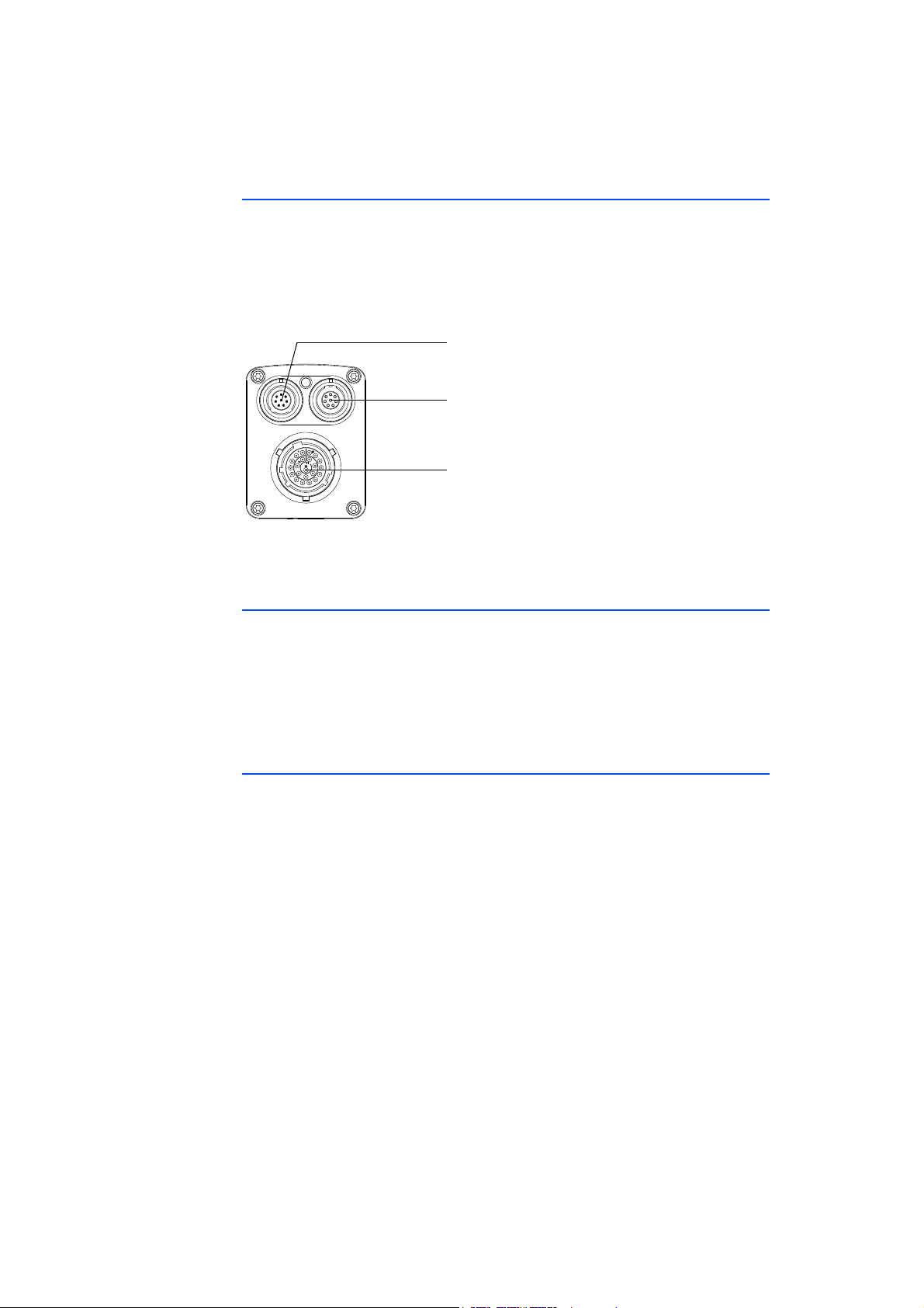
All ports of the ES400 measuring modules are on the front of the device (see
Fig. 3-2 on page 17).
The LEMO and Souriau connectors used adhere to protection class IP67. All ports
are reverse-polarity protected due to the exclusive use of coded LEMO or Souriau
connectors.
Fig. 3-2 Front
3.4.1 “Sensor” Port
The front of the ES415.1 features a 22-pin Souriau port to which four sensors
can be connected using a adapter cable. An individual sensor power supply port
is available for each sensor.
The use of a “cable tail” or “whip” solution with just one connector makes it
possible to change the modules quickly within complex test setups.
3.4.2 Daisy Chain Ports (“IN”, “OUT”)
The modules are connected using a daisy chain topology. This means each module has an explicit input socket and an explicit output socket. The Ethernet data
line and the supply voltage are routed through the daisy chain ports of the module:
• “IN” (input)
• “OUT” (output)
The PC, the modules ES523, ES59x, ES600.2, ES891, ES910.3 or the Drive
Recorder ES720 are connected at the “IN” port (input). The “OUT” port (output)
is connected to the following module of the ES400 line or remains free on the
last module of the chain.
ES415.1 - User’s Guide 17
Page 18
ES400 Product Family ETAS
3.5 LED
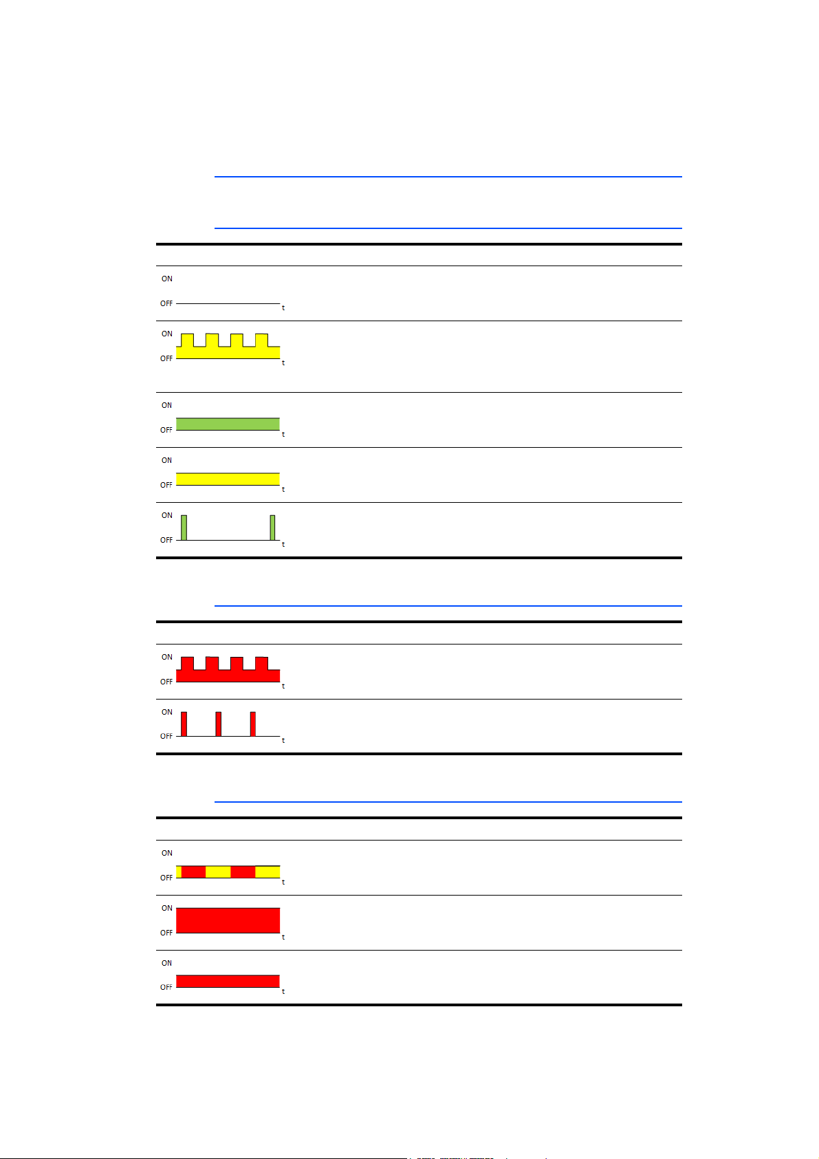
Every module has an LED. It indicates the following states of the module:
3.5.1 Operational State
Display State
off No power supply to the
module
yellow flashing
0,25 s on / 0,25 s reduced
green illuminated
semi bright
yellow illuminated
semi bright
green flashing
0,1 s on / 1,9 s off
3.5.2 Service State
Display State
red flashing
0,25 s on / 0,25 s reduced
red flashing
0,1 s on / 0,6 s off
Initialization of the module
not yet complete Further modules in a chain
not initialized yet
Normal
At least one sensor supply
voltage is activated.
Standby
No Ethernet connection
established
Module identification
Update of the firmware /
HDC
3.5.3 Functional State
Display State
yellow-red flashing
0,5 s yellow reduced /
0,5 s red reduced
red illuminated
fully bright
red illuminated
semi bright
Warning
Overload on a sensor supply
voltage channel
Error during self-test
Internal error
ES415.1 - User’s Guide18
Page 19
ETAS Hardware Description
4 Hardware Description
This chapter contains information on the following topics:
• "Features of the ES415.1" on page 19
• "Block Diagram" on page 20
• "Sensor Channels" on page 21
• "Data Transfer" on page 26
• "Power Supply" on page 31
• "Configuration" on page 33
• "Tool Integration" on page 33
• "Firmware Update" on page 33
• "Calibration" on page 33
4.1 Features of the ES415.1
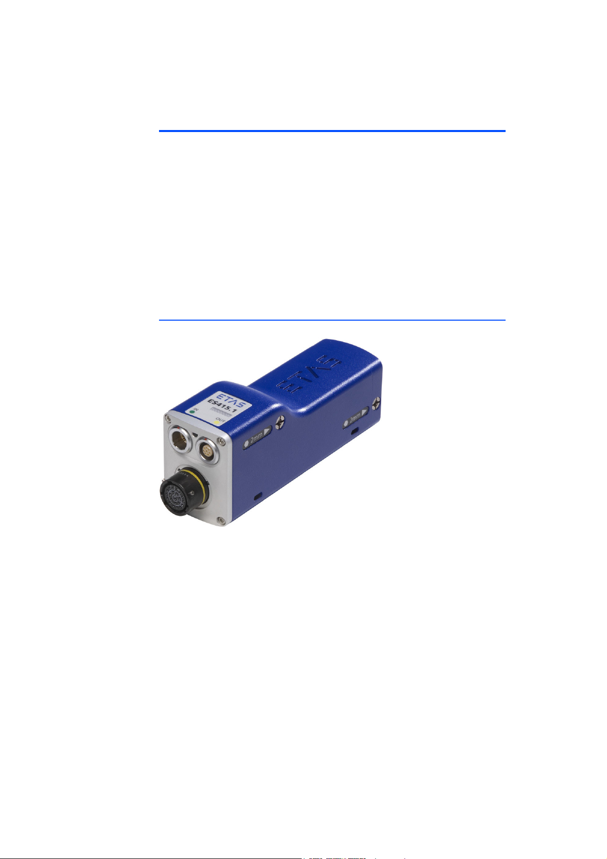
Fig. 4-1 ES415.1 Housing
The ES415.1 High Definition A/D Module with Sensor Supply is a member of the
family of ES400-Modules. The ES415.1 can acquire analog voltages at four input
channels. There is a sensor supply for every channel.
• 4 electrically isolated A/D channels, separately configurable
• Measure range 100 mV to 60 V
• Signal conditioning cable available for expanded measure ranges
• Sample rate 0.5 Hz to 100 kHz (measuring and calibrating)
• Adjustable short circuit-proof sensor supply voltage (5 V to 15 V)
• Auto detect and configuration of sensors possible with TEDS (Transducer
Electronic Data Sheet)
For the complete technical data of the ES415.1, refer to the chapter "Technical
Data" on page 70.
ES415.1 - User’s Guide 19
Page 20
Hardware Description ETAS
Channel 4
...
Synchronous Sampling
Channel 1
+/-0,1 V
+/-1 V
+/-10 V
+/-60 V
16-Bit A/D
Converter
Digital Filter
16-Bit D/A
Converter
Sp l i t t e r
Cab l e
Connector
TEDS Inter face
(cable recognit ion)
IN
(Host direction)
100 MBit /s
Overload
Detection
TEDS Inter face
(sensors and transducer
configuration)
Volt age
Regulator
Diagn ost ic
Unit
100 MBit /s
Et h e r n e t
Traffic
Detect ion
On
Automatic
OUT
(Next module)
Measurem ent Cont roll er
Tim e
Synchronization
Unit
Et h e r n e t
Ph y
Et h e r n et
Ph y
Protocol Engine
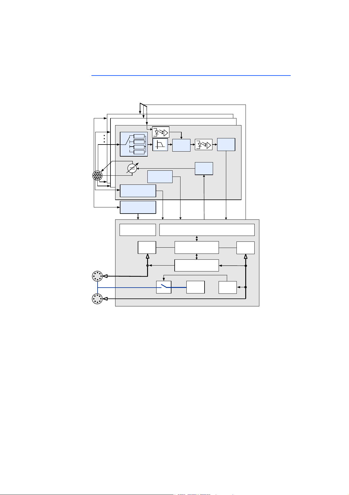
4.2 Block Diagram
The ES415.1 is a module with four identical sensor channels, two shared Ethernet interfaces and a power supply.
Fig. 4-2 Block Diagram
ES415.1 - User’s Guide20
Page 21
ETAS Hardware Description
Note
Bypass
f
C,FIR
AnalogInput+
LowpassFilter
A
D
AdjustableGain A/DConverter
AnalogInput‐
VoltageRange
f
C,AAF
f
S,AD
Control
DigitalFilter,
Decimator
Buffer
Sample1Sample2Sample3Samplen
f
S,INCA
CTRL
ADC
4.3 Sensor Channels
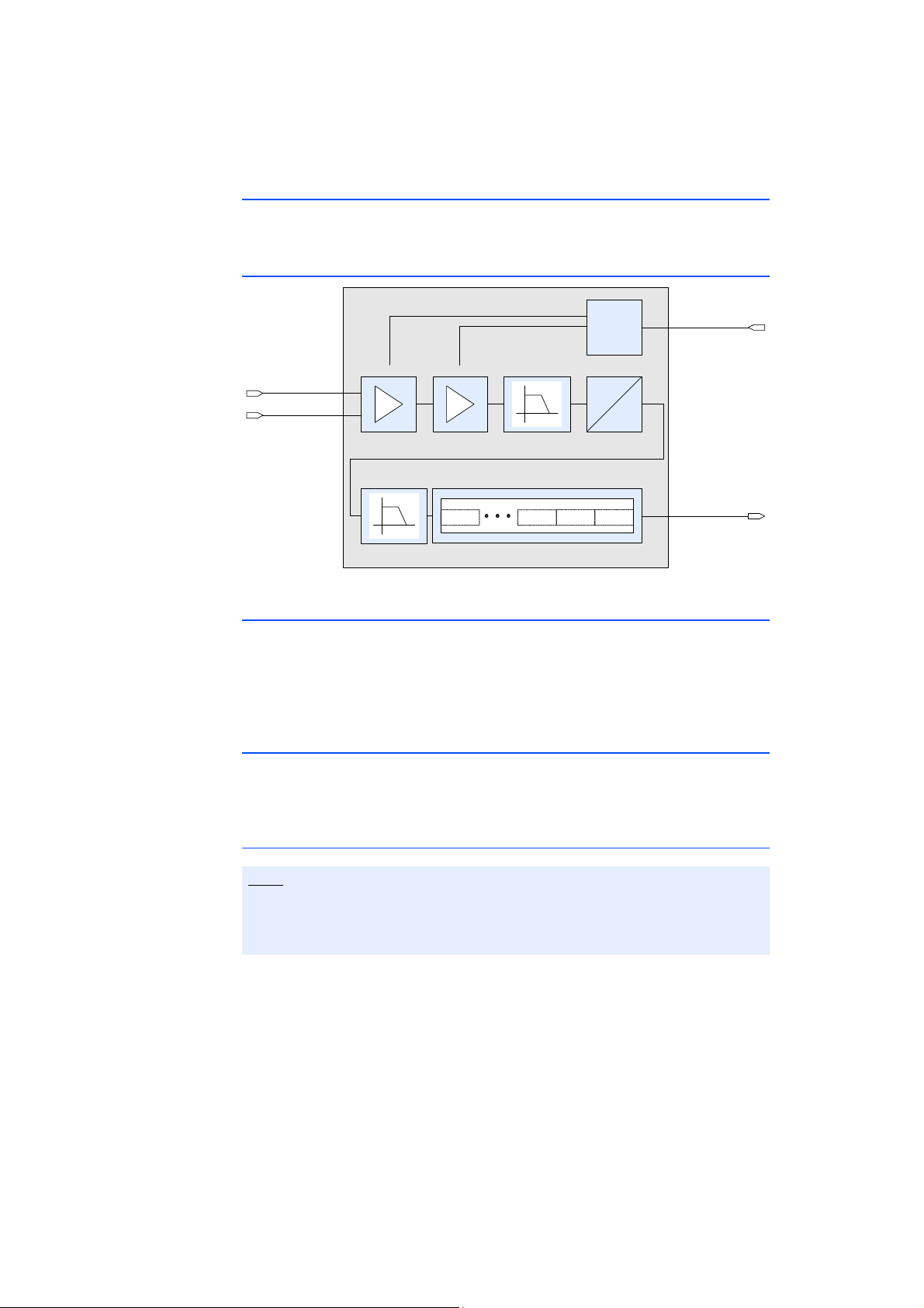
All sensor channels of the ES415.1 are identical. Every sensor channel consists of
the function groups Signal Processing and Filter as well as Sensor Power Supply.
4.3.1 Signal Processing and Filters
Fig. 4-3 Signal Processing and Filters of a Sensor Channel
4.3.2 Amplifier and analog Filter
The level of the input signal is limited in every sensor channel after the overvoltage protection by a capacitively compensated voltage divider. An amplifier
adjusts the input signal to the following analog anti-aliasing filter according to
the selection of the input voltage range. This 4th order analog filter with Butterworth characteristics has a cutoff frequency of 50 kHz.
4.3.3 A/D Converter
An A/D converter digitizes the output signal of the analog filter. The individual A/
D converter available in every sensor channel guarantees synchronous sampling
of the measure signals.
Sample Rates for Rapid Prototyping Applications
For Rapid Prototyping applications, the sample rate of the ES415.1 module is
limited to a maximum of 10 kHz. The sample rates 100 kHz, 50 kHz and
20 kHz are available only for measurement and calibration applications.
Sample rates to 10 kHz can be configured for measurement and calibration
applications as well as for Rapid Prototyping applications in the application software.
To avoid the IRQ overload at the I/O port of the ES910.3, the sample rate of the
ES415.1 module in this mode is automatically limited to 10 kHz.
If the ES415.1 would be operated at high sample rates for Rapid Prototyping
applications, the ES910.3 could no longer process the data of the ES415.1 or
other ETAS daisy chain modules due to IRQ overload at its I/O port and would
discard the data.
ES415.1 - User’s Guide 21
Page 22

Hardware Description ETAS
If the user selects a higher sample rate in this mode (100 kHz, 50 kHz and
20 kHz), the application software prevents the initialization of the hardware and
points to the limited selection of sample rates.
4.3.4 Digital Filter
A digital filter then processes the digital signal. The parameters of the CIC filter
(Cascaded-Integrator-Comb filter) are automatically set upon selecting the sample rate in the configuration software. The digital filter can be switched off,
parameters of the filter cannot be configured.
The data is written to a data buffer at the output of the digital filter. It can be
queried there by the application program.
Compensating Group Delay
The group delay is the time it takes the input signal of an analog or digital filter
to pass the filter. In the application program (e.g. INCA MDA), the signal must be
delayed to compensate for the group delay.
A special feature of the ES415.1 is the compensation of the group delay within
the module. The group delays of the analog anti-aliasing filter and the configurable digital filter are taken into consideration in this process. The signal in the
application program (e.g. in MDA) no longer has to be delayed to compensate
for the group delay.
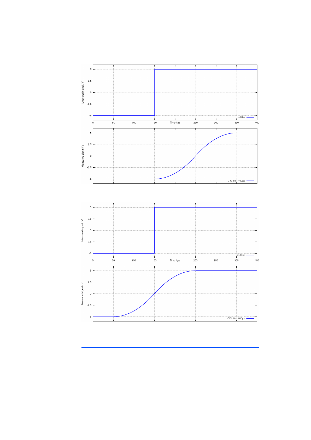
Examples
To represent the group delay with digital filters, a test signal was sent to two
filters of the same type:
• Filter A without compensation of the group delay
• Filter B with compensation of the group delay
The configuration of both filters is identical. The test signal is sampled with the
sampling rate f
quency f
= 200 Hz.
C,CIC
= 2 kHz (0.5 ms). The filter channel was set to a cutoff fre-
S,INCA
Fig. 4-4 and Fig. 4-5 on page 23 show the relevant signal trace - in the upper
part of the figure without a filter, in the lower part of the figures with a filter and
without or with group delay compensation respectively.
ES415.1 - User’s Guide22
Page 23
ETAS Hardware Description
Fig. 4-4 Filter A: f
Fig. 4-5 ES415.1 Filter B: f
= 10 kHz (without compensation of the group delay)
C,CIC
= 10 kHz (with compensation of the group
C,CIC
delay)
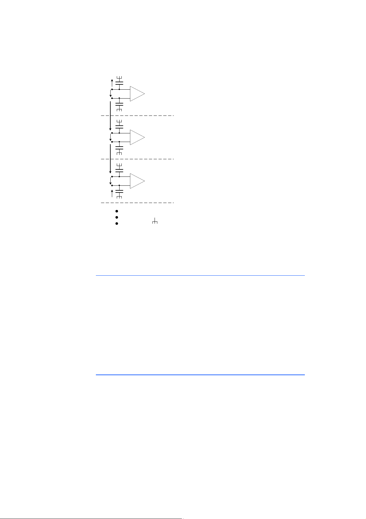
4.3.5 Maximum Input and Common-Mode Voltages
The maximum input voltage between two inputs and the maximum voltage
between an input and the case ground is 60 V DC/ 30 V AC. For an explanation
of the maximum input and common-mode voltages, see Fig. 4-6 on page 24 and
the example.
ES415.1 - User’s Guide 23
Page 24
Hardware Description ETAS
+
-
+
-
+
-
Kanal x
Kanal y
Kanal z
Galvanische Trennung
Galvanische Trennung
Gehäusemasse
C
C
C
C
C
C
U
in+
U
in+
U
in+
U
in-
U
in-
U
in-
U
inx
U
iny
U
inz
U
CMx y
U
CMy z
U
c
U
c
Fig. 4-6 Maximum Input and Common-Mode Voltages
All capacitors between the inputs (U
and U
in+
) and case ground have the same
in-
capacity. The maximum voltage between any input and case ground is also 60 V
DC/ 30 V AC.
Example
For the given input voltages U
the maximum allowed common-mode voltage U
U
= 10 V
inx
U
= 5 V
iny
U
= 10 V
inz
U
= 15 V
CMxy
max (U
inx
+ U
iny
+ U
inz
+ U
10 V + 5 V + 10 V + 15 V + max (U
max (U
) = 60 V - 40 V = 20 V
CMyz
CMxy
inx
+ U
, U
, U
and the common-mode voltage U
iny
CMyz
CMyz
inz
) = 60 V
) = 60 V
is to be calculated.
CMyz
CMxy
,
4.3.6 Galvanically Isolation
The sensor channels are galvanically isolated from each other and from the
power supply. The digitized transfer of the measurements on an Ethernet connection implicitly results in a separation of the sensor channels from the supply
voltage.
ES415.1 - User’s Guide24
Page 25

ETAS Hardware Description
Note
4.3.7 Sensor Supply
Every sensor that can be switched to the ES415.1 has an individual sensor supply
voltage which can be set separately.
The cable connected to the sensor port of the ES415.1 transfers both the sensor
supply voltage and the sensor output voltage for the sensor. Additional cables or
an additional external power supply for the sensor supply voltage are not
required.
The sensor supply voltage is generated from the module operating voltage in
every sensor channel. The sensor supply voltage can be modified in steps. The
user can switch off the sensor supply voltage of each sensor channel in the application program, select one of the defined values between +5 V and +15 V or
enter or define any value within the value range.
Behavior for Rapid Prototyping Applications
The already existing sensor voltage is briefly interrupted at the start of the Rapid
Prototyping model on the ES910.3.
Electrical Isolation
The ground of the sensor supply voltage channels is connected with the ground
of the operating voltage of the module and protected with a fuse.
The supply voltages of the sensors are not galvanically isolated towards the
operating voltage of the module.
Overvoltage Protection
Each sensor supply output is protected against overvoltages. Exceeding the maximum value trips a fuse.
Fuses
If a sensor supply output (ground) is connected with the supply voltage (positive)
of the module, it trips a fuse.
Defective fuses cannot be replaced by the user. Please return defective modules
to ETAS. Notes about the process are available from the local ETAS sales and
service offices. The contact information is located in the chapter "ETAS Contact
Addresses" on page 108.
Overload
Upon exceeding the maximum output of a channel, the output voltage of this
channel is reduced.
Short-circuit Detection
In case of a short circuit of a sensor supply output (positive) to ground, the sensor
power supply automatically switches off this channel.
Information in the Application Program
In case of short circuits and tripped fuse, the application program receives analyzable channel-specific information.
ES415.1 - User’s Guide 25
Page 26
4.4 Data Transfer
Note
SA
48
UDP Head er
IFG
min. 96
IP Head er
DA
48
Pr e56So F
8
CRC
32
Typ e
16
DATA
n*8
XCP M essa g e 1 XCP M essa g e n
...
XCP on Ethernet Message
XCP Header XCP Package
DATATIM E STAM PDAQFI LLPI DCTRLEN
Embedded UDP/IP
Embedded XCP
IEEE802.3 (Ether net)
For data transfer, the ES930.1 as well as the ES4xx and ES63x modules use a
100 Mbit/s Ethernet network connection in duplex operation. The data transfer
can be adapted flexibly to suit the test setup and the measurement task.
The complete Ethernet bandwidth is available for both measure data and control variables.
Calibration procedures can take place in a Rapid Prototyping application without delay with measure data being acquired at the same time.
4.4.1 Communication Protocols
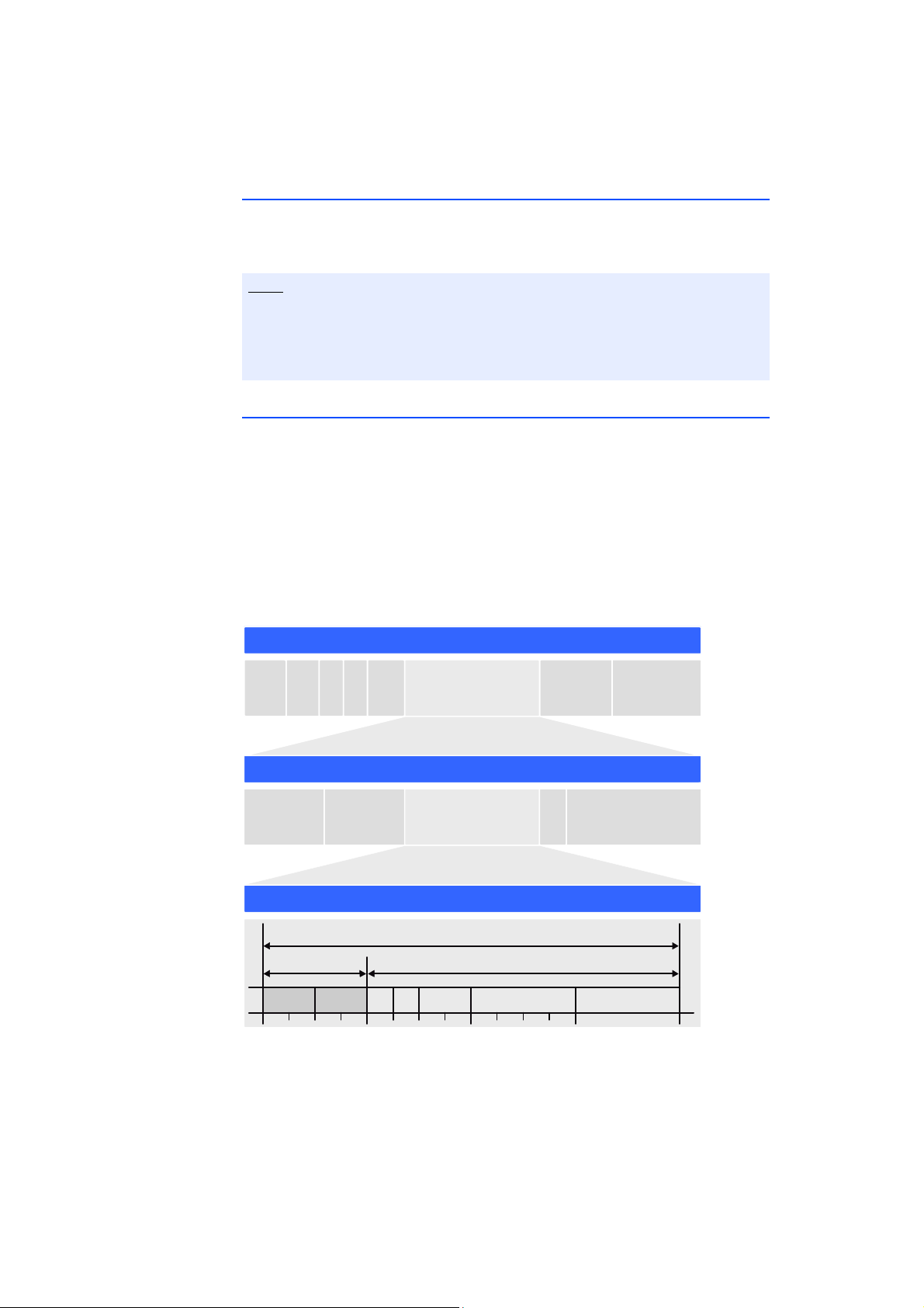
The universal ASAM measure and calibration protocol XCP is used for serial communication. On the Ethernet transport and network layer, the UDP/IP protocol is
used (see Fig. 4-7 on page 26).
Within the XCP protocol, the modules transfer, among other things, module ID,
time stamp and measure and/or stimulation data in an extremely precise and
predictable time pattern. The communication protocol used for the modules
avoids repeated transfer of protocol data, which takes place, for example, in
handshake-based systems. This makes a high bandwidth available for reference
data.
ETAS
Fig. 4-7 Message Format “XCP on UDP” (Schematic)
Using the UDP/IP standard for data transfer makes it possible to connect the
modules directly to a PC, a router or a switch. In XCP communication, the PC has
the master function.
ES415.1 - User’s Guide26
Page 27

ETAS
Note
No real-time requirements are made. Data acquisition on a PC, which generally
does not have to fulfil high real-time requirements, can thus be connected
directly to an ES400 chain. With a real-time-capable master, such as, for example, a Rapid Prototyping system, lots of different kinds of I/O signal can be
accessed with extremely short cycle times.
The communication protocol used by the ES400 family makes it possible for
third-party suppliers to use the communication protocol for their own, nonETAS applications once the modules have been configured with the „ES4xx
Configuration Tool from ES4xx_DRV_SW“ .
4.4.2 Realization
Time Slice Procedure
The modules in the daisy chain transfer the data to the master using a 100 MBit/
s Ethernet connection time-controlled, i.e. without being prompted. The PC
assumes the function of the master. In the network, the modules respond like a
single Ethernet device with one MAC address.
All daisy chained modules have a generator which is only activated in the last
module of each chain after the test setup has been connected to the PC. The
frequency of the generator or the period duration of the time slices generated
can be set in the application program. It corresponds to the measuring frequency
of the measurement channel with the highest acquisition rate in the chain.
A binary counter linked to the generator periodically counts the time slices generated (value range: 2
vant number of time slices in the IP header. The Ethernet frames are transferred
from module to module within the chain.
Each module in the chain receives bandwidth to transfer its measure data in
freely selectable time slices assigned within the period of the binary counter. The
module uses the number of the time slice to determine whether it can insert an
XCP message with its measure data into the current time slice.
The fastest module, which determines the period duration of the time slices generated, transfers data in every time slice. An Ethernet frame then contains at least
one XCP-on-Ethernet data package. The length of the Ethernet frame transferred inside a time slice increases with the number of modules which can insert
their data into this time slice.
The numbering of the time slices ensures, for example, that two modules which
work with half the sampling rate of the generator never attach their data to the
same Ethernet frame. One module uses only the odd frame numbers and the
other only the even ones. This mechanism also ensures for certain that the
assigned frames do not exceed the length of a time slice.
The measure data is automatically distributed to the frames so that the available
bandwidth is used perfectly.
The time slice procedure makes both measurements of fast signals and the acquisition of a large number of channels with a low sampling rate possible.
16
= 65536). The last module in the chain sends the rele-
ES415.1 - User’s Guide 27
Page 28

ETAS
Note
If a few fast signals and lots of slow ones are acquired in a chain, the slow signals
can be transferred in time multiplex procedure.
Due to data transfer by Ethernet, there are virtually no limitations in terms of
the number of modules in a module chain even with fast sampling rates.
Clock Generator for Synchronizing Modules
The clock generator for the synchronization of the modules is either the first
module in an module chain or the network module ES600. In both cases, the
measure data is synchronized with a tolerance of one microsecond. Using an
ES600 network module, several ES4xx/ES63x/ES93x chains can be synchronized
with each other or with the modules of the ES600 series. The ES4xx/ES63x/ES93x
and ES600 modules add the relevant time stamp to the Ethernet data package
for every measure value. The exact assignment in terms of time of the measure
data of the ES4xx/ES63x/ES93x and ES600 modules used resulting from this
makes precise analysis of the correlations of measure signals possible.
Synchronizing the Modules and INCA Signal Processing
Data transfer does not require synchronization of the local timebases of the
ES4xx/ES63x/ES93x modules. The time stamps are still synchronized by the system to be able to correlate measure data and sampling times of different modules in terms of time after data transfer. A precise time and drift synchronization
takes place in the modules via a hardware connection.
No bandwidth is required for this, unlike time synchronization in acc. with
IEEE1588 (Precision Time Protocol). The modules add the time stamp to the
Ethernet data package for every measure date.
The combination of time stamp synchronization, full duplex and time slice procedure results in a very high reference data rate of the modules.
ES415.1 - User’s Guide28
Page 29
ES415.1 - User’s Guide 29
Cont rol variables
Measured
values M1
Rate: 10 kHz
Signal injection
Signal extract ion
Fr am e
Gen era t or
(inak tiv)
MODULE 1
Control variables
Measured
values M2
Rate: 10 kHz
Signal injection
Fr am e
Gen era to r
(inak tiv)
MODULE 2
Signal extract ion
Control variables
Measured
values M3
Rate: 10 kHz
Signal injection
Si gnal ext raction
Fr am e
Gen era to r
(10 kHz)
MODULE 3
Et h e rn e t
100 Mb it/s
PC
Ethernet Frame 1
M3 M2 M1H R M3 M2 M1H RM3 M2 M1H R
t [µs]
2000 100
Ethern et Frame 2
Ethernet Frame 65536
Periode Frame Generat or
M3 M2 M1H R
Ethernet Frame 3
M3 M2 M1H R
Ethernet Frame 4
M3 M2 M1H R
Ethernet Frame 5
300
500
400
H UDP/IP Header
R
Reserved for additional
com mu ni cat io n
Mn Measured values of module n
4.4.3 Examples
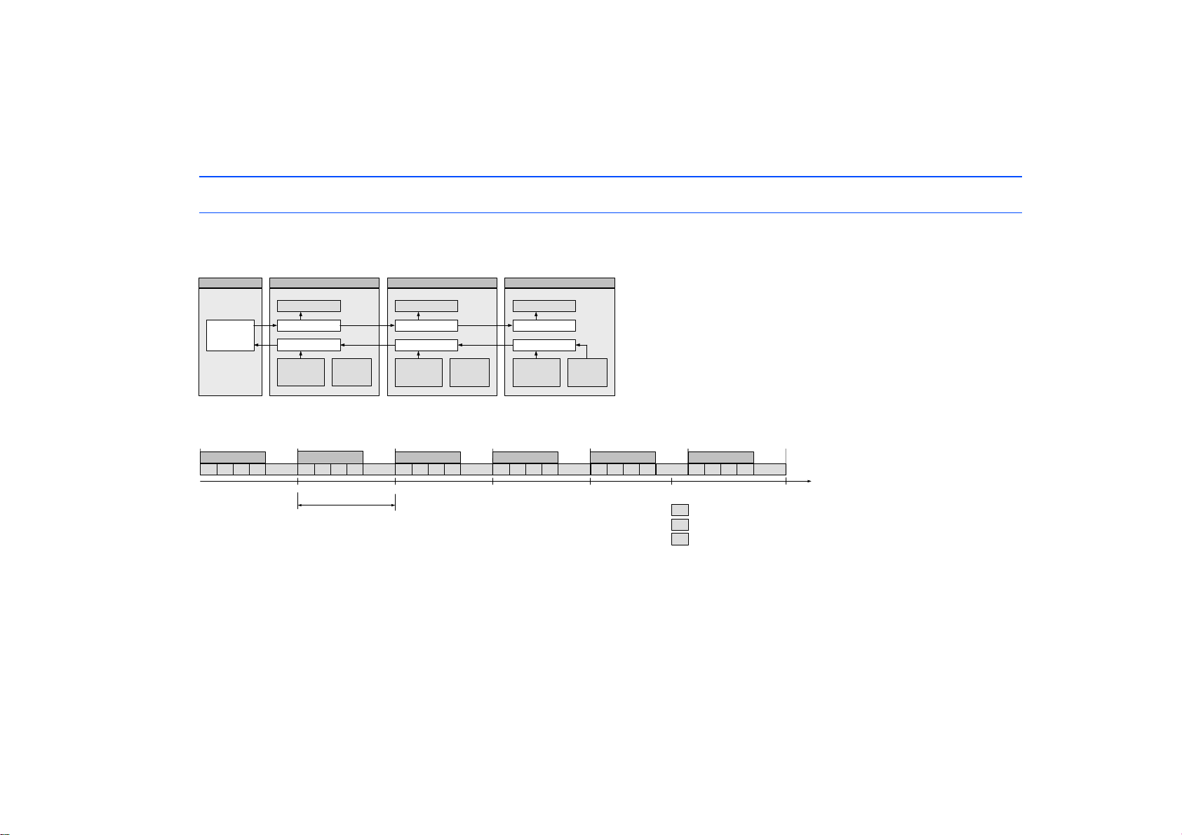
Example 1
Fig. 4-8 on page 29 shows an example of an application with three concatenated ES400 modules with the same acquisition rates. The
transfer scheme for this configuration is shown in Fig. 4-9 on page 29.
Fig. 4-8 Time-Multiplex Data Transfer Between an ES400 Module Chain and a PC
ETAS
Fig. 4-9 Transfer Scheme for Example 1 (Simplified, Not True to Scale)
In this example, the third module periodically generates 2
16
(65536) time slices each 100 microseconds long. Modules 1, 2 and 3 acquire
measurements with the same rate of 10 kHz each. Module 1, Module 2 and Module 3 link their measurements to each time slice (see
Fig. 4-9 on page 29).
Independently of this, control variables can be transferred at the same time from the PC to the modules.
Page 30

ES415.1 - User’s Guide30
Co ntrol variables
Measured
values M1
Rate: 10 kHz
Signal injection
Si gnal ext raction
Fr am e
Gen era t or
(inakt iv)
MODULE 1
Co ntrol variables
Measured
values M2
Rat e : 2 kH z
Signal injection
Fr am e
Gen era t or
(inakt iv)
MODULE 2
Si gnal ext raction
Co ntrol variables
Measured
values M3
Rat e : 5 k Hz
Signal injection
Si gnal ext raction
Fr am e
Gen erat o r
(10 kHz)
MODULE 3
Et h e rn e t
100 Mb it/s
PC
Ethern et Frame 1
M1H R M1H RM3 M2 M1HR
t [µs]
2000 100
Frame 2Fr. 65536
Periode Frame Generator
M3 M1H R
Frame 3
M1H R
Frame 4
M3 M2 M1H R
Ethern et Frame 5
300
500
400
H UDP/IP Header
R
Reserved for additional
communication
Mn Measured values of module n
Example 2
Fig. 4-10 on page 30 shows an example in which three modules with different acquisition rates are linked to each other. The transfer
scheme for this configuration is shown in Fig. 4-11 on page 30.
Fig. 4-10 Time-Multiplex Data Transfer Between an ES400 Module Chain and a PC
Fig. 4-11 Transfer Scheme for Example 2 (Simplified, Not True to Scale)
In this example, the third module periodically generates 2
16
(65536) time slices (Ethernet frames) each 100 microseconds long. The ES400
modules 1, 2 and 3 acquire measurements at a rate of 10 kHz, 2 kHz and 5 kHz. Module 1 links its measurements to each Ethernet frame,
module 2 to every fifth Ethernet frame and module 3 to every second Ethernet frame (bottom figure).
Independently of this, control variables can be transferred at the same time from the PC to the modules.
ETAS
Page 31

ETAS
Note
4.5 Power Supply
4.5.1 Supply Voltage
DC/DC converters in every module guarantee both the operation as well as the
launch of the ES400 modules with supply voltages between 5 V and 50 V DC
over the entire temperature range.
With the power supply management of the ES415.1, you can use an automatic
power-saving feature (“Standby”) as well as a “Wake Up” function via the Ethernet interface.
4.5.2 Supplying the ES400 Modules via the Connecting Line
In the simplest application case, the modules are directly linked to one another.
They are connected to the supply voltage via the previous module all the way.
4.5.3 Additional Supply of the ES400 Modules via a Y-Boost Cable
If the supply voltage at the input of a module is too low because of the current
consumption of the previous modules, multiple feeding of the supply voltage can
guarantee this and the following modules sufficient supply voltage in longer
module chains.
In this application case, you have to split the module chain. Swap the existing
connection cable between the two modules for a Y boost cable for additional,
direct feeding of the supply voltage. The module chain is now closed again and
the power supply of the following modules guaranteed.
The special design of the Y boost cable avoids reverse feeding into the front parts
of the module chain and thus arising potential differences.
When is it necessary to use a Y boost cable?
An exact calculation of the current consumption of a module chain is only possible if numerous variables are known:
• supply voltage of the first module at the input
• minimum supply voltage at the last module of the chain
• number and type of the modules
• consumption of sensor power supply of the connected sensors
• cable length
•cable type
• ambient temperature
The necessary minimum voltage for supplying power to the system must be
determined individually for each test set-up.
Please contact our local experts to discuss your particular ES415.1 configurations.
Example 1: For module chains which are equipped exclusively with ES410.1 or
ES441.1, ETAS recommends the use of Y boost cables if the length of the module
chain is longer than 10 modules.
ES415.1 - User’s Guide 31
Page 32

ETAS
Note
Example 2: For module chains which are equipped exclusively with ES411.1 or
ES413.1 or ES421.1, ETAS recommends the use of Y boost cables if the length of
the module chain
• is longer than 16 modules (without sensor feeding) or
• is longer than 10 modules (with sensor feeding).
Example 3: For module chains which are equipped exclusively with ES415.1 or
ES420.1, ETAS recommends the use of Y boost cables if the length of the module
chain
• is longer than 8 modules (without sensor feeding) or
• is longer than 5modules (with sensor feeding).
Example 4: With a minimum voltage of 7.7 V, no additional feeding is necessary with a Y cable if the module chain consists of the following modules:
• nine ES420.1 or ES421.1 and
• four ES410.1 or ES411.1 or ES413.1 (without sensor feeding) and
• one ES441.1
Example 5: With a minimum voltage of 7.7 V, no additional feeding is necessary with a Y cable if the module chain consists of the following modules:
• five ES420.1 or ES421.1 and
• two ES415.1 (without sensor feeding) and
• one ES441.1
Example 6: With a minimum voltage of 9 V, no additional feeding is necessary
with a Y cable if the module chain consists of the following modules:
• nine ES420.1 or ES421.1 and
• four ES410.1 or ES411.1 or ES413.1 (with sensor feeding) and
• one ES441.1
Example 7: With a minimum voltage of 9 V, no additional feeding is necessary
with a Y cable if the module chain consists of the following modules:
• five ES420.1 or ES421.1 and
• two ES415.1 (with sensor feeding) and
• one ES441.1
All example applies at 85 °C ambient temperature.
ES415.1 - User’s Guide32
Page 33

ETAS
Note
4.6 Configuration
The configuration of the ES415.1 is performed entirely via the GUI within INCA.
The configuration of the individual channels is saved either in INCA or in the
individual ES400 modules. In the first case, you can prepare settings for specific
measure tasks, e.g. in the lab. The second case is of interest to users who share
a test carrier with a corresponding ES400 test setup. In this way, several users can
call up the saved configuration directly from the modules.
4.7 Tool Integration
The ES400 modules can be selected and configured in INCA and support the
open protocol XCP-on-Ethernet. This enables easy integration of the modules
into other measure software.
The measure system can be connected directly to the PC’s Ethernet port. No
additional devices or interface converters are necessary.
4.8 Firmware Update
The firmware of the module can be updated by the user so that future versions
of the module can also be used. The firmware update is done with the help of
the service software "Hardware Service Pack" (HSP) from the connected PC.
During a firmware update, neither the voltage supply nor the Ethernet connection may be interrupted!
4.9 Calibration
A calibration service for your ES415.1 is available. To ensure reliable accuracy of
the measurements, you should calibrate the ES415.1 once a year.
Information on the last calibration is stored in the device.
Please contact your local ETAS representative for information on obtaining the
calibration service. You can find the contact information in the Chapter "ETAS
Contact Addresses" on page 108. For information on ordering the calibration
service, refer to the Chapter "Device calibration" on page 107.
ES415.1 - User’s Guide 33
Page 34
Getting Started ETAS
CAUTION!
CAUTION!
5 Getting Started
This chapter contains information on the following topics:
• "General Installation Recommendations" on page 34
• "Assembly" on page 36
• "Drilling Template" on page 50
• "Applications" on page 51
• "Wiring Examples" on page 53
• "Wiring" on page 58
5.1 General Installation Recommendations
5.1.1 Assembly Environment and Components for Attaching the Module
The module can be damaged or destroyed.
The modules of the ES400 line are only admissible for assembly and
operation on components or in locations which guarantee adherence
to the technical data of the modules during operation (see chapter 7
on page 70).
Adhere to the technical data of the modules for operation, such as
• the vibration resistance of the modules (only assemble modules on sprung
masses, for example, and not on wheel suspensions or directly on the
engine) and
• the temperature resistance of the modules (for example do not assemble
modules on the engine, turbocharger, exhaust manifold or within their
vicinity).
5.1.2 Potential Equalization in the Vehicle and Mounting the Modules
Potential equalization in the vehicle over the shield of the
Ethernet connecting cables of modules may occur!
Mount the modules only to components with the same electrical
potential or insulate the modules from the components.
ES415.1 - User’s Guide34
Page 35
ETAS Getting Started
CAUTION!
a^b
5.1.3 Guarantee of Features as defined by IP67
Loss of Features as defined by IP67!
Water standing at the pressure balance element damages the membrane!
Please observe which way the module is pointing when installing vertically!
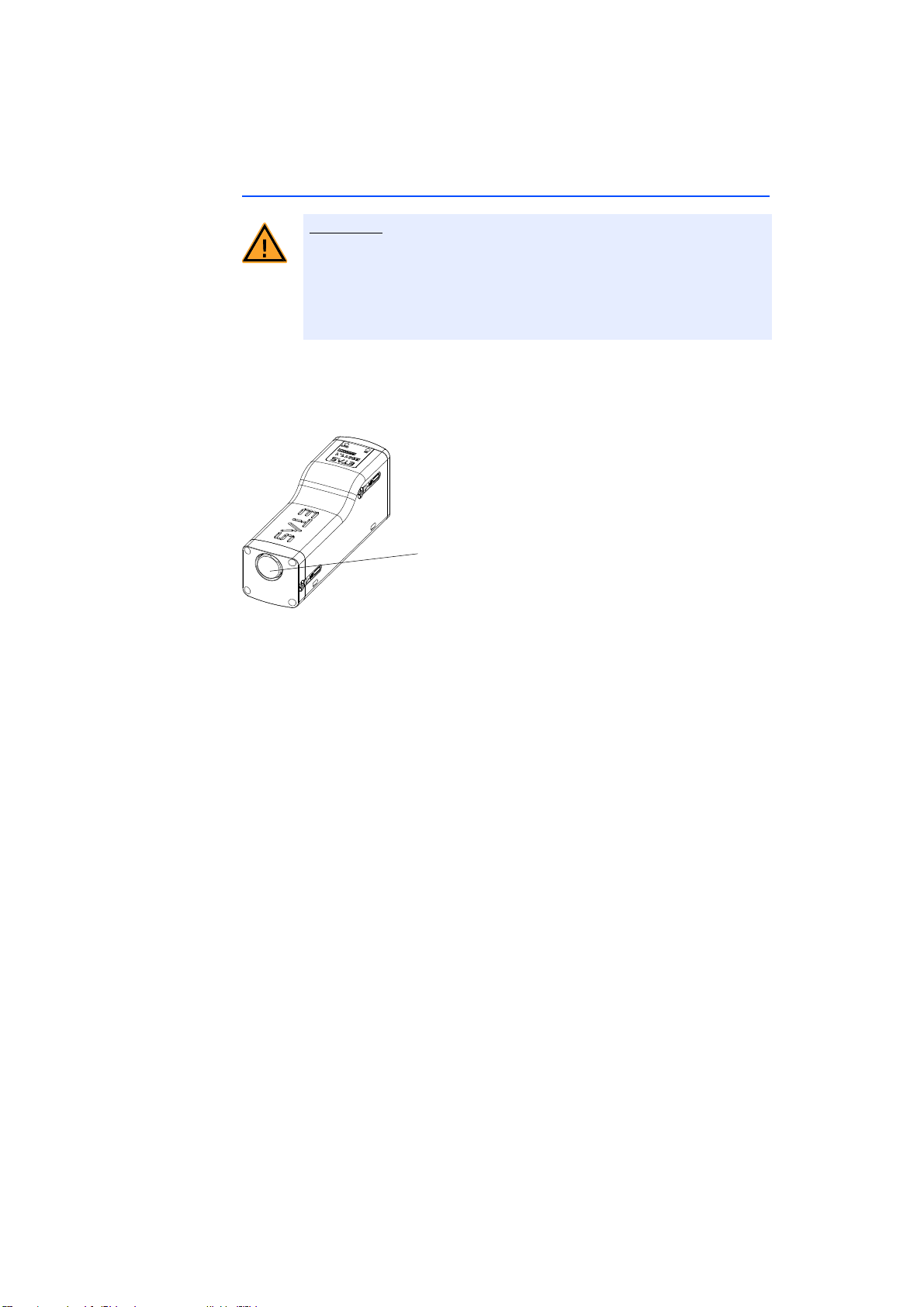
If installing the ES400 modules where water or other liquids could collect, install
the modules so that the (black) pressure balance element on the back of the
modules is not pointing upwards or that liquids can drain away.
Fig. 5-1 Position of the Pressure Balance Element
Standing liquids or liquids which do not flow away from the pressure balance
element can permanently damage the membrane. The module then loses the
features defined by IP67.
ES415.1 - User’s Guide 35
Page 36
Getting Started ETAS
fенЙЦк~нЙЗ
^ллЙг Дду =bдЙг Йен л
lйЙебеЦл= Сзк
`~ДдЙ=c~лнЙеЙкл
5.2 Assembly
5.2.1 How to Connect and Attach ES400 Modules
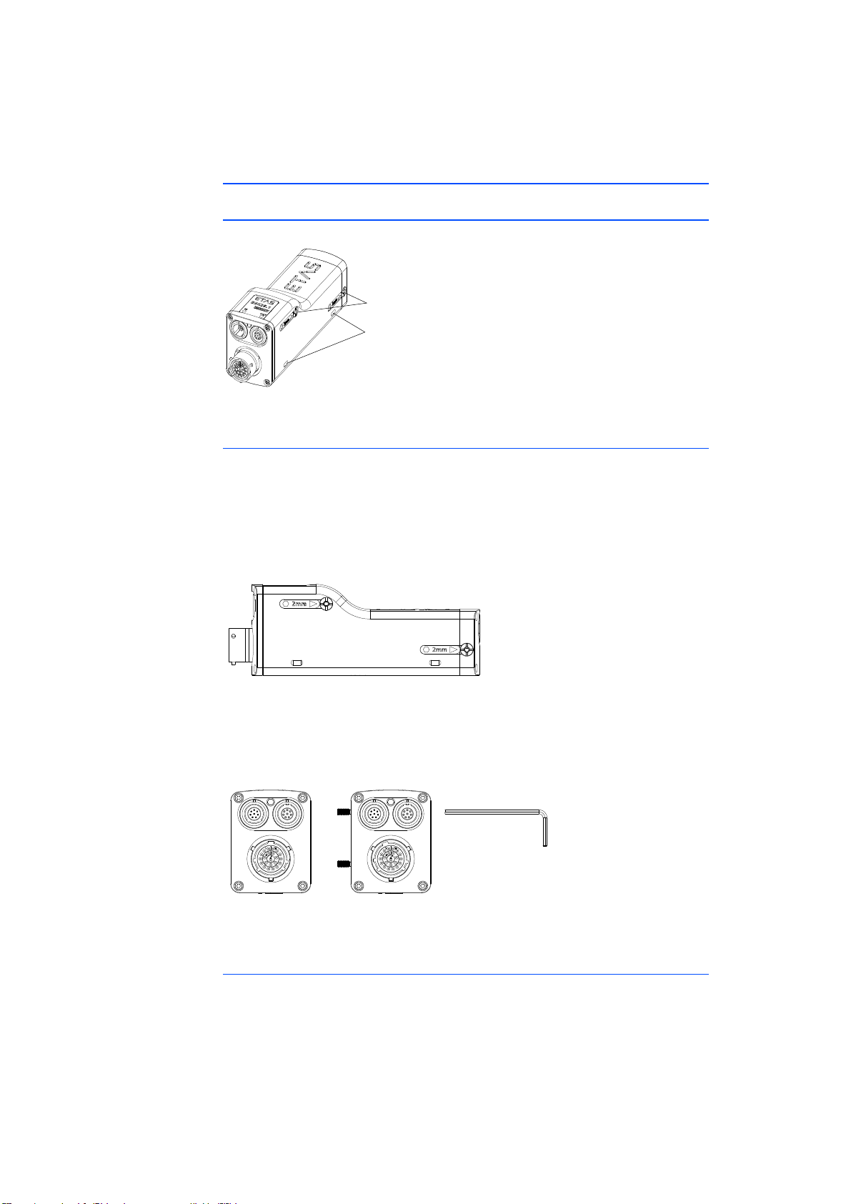
Fig. 5-2 How to Attach ES400 Modules
Integrated Assembly Elements
Every ES400 module has two integrated assembly elements to enable different
assembly possibilities. If several modules are required in one location, they can be
connected quickly, without any additional parts, using the integrated assembly
elements to form a measuring instrument block (cascading). The two integrated
assembly elements also make it possible to screw the modules directly onto other
components (parts of the vehicle body, units).
Fig. 5-3 Accessing the Integrated Assembly Elements
You can access and use the two integrated assembly elements of a module via
the holes indicated (see Fig. 5-3 on page 36) on the right-hand side of the module.
Fig. 5-4 Unscrewed Integrated Assembly Elements
Openings for Cable Fasteners
Every module base has two openings each on the right and left-hand side for
attaching the modules to other components using cable fasteners.
ES415.1 - User’s Guide36
Page 37
ETAS Getting Started
Note
Examples for mounting
Examples for mounting using the different possibilities to connect and attach
ES400 modules are:
• Connect ES400 modules with the integrated assembly elements (cascading)
• Attaching ES400 modules with the integrated assembly elements:
– on DIN rails with ES4xx angle brackets (left)
– on other components
• Attaching ES400 modules with screws:
– on DIN rails with ES4xx angle brackets (right)
– on other components
• Attaching ES400 modules with cable fasteners:
– on DIN rails with ES4xx angle brackets (left)
– on DIN rails with ES4xx angle brackets (right)
– on other components
5.2.2 Connecting Several ES400 Modules Mechanically
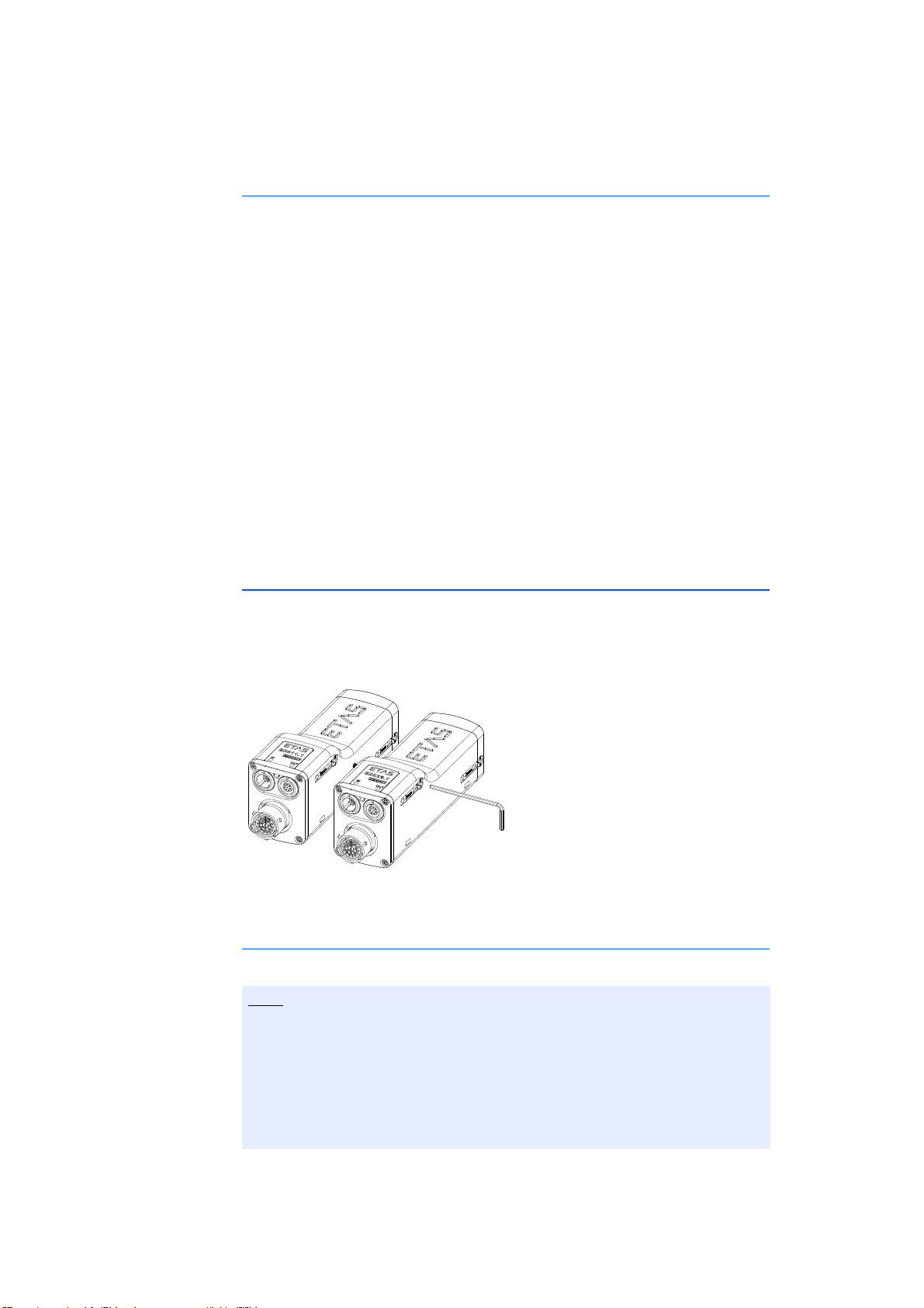
You can combine any ES400 modules with each other using the integrated
assembly elements of the ES400 modules.
Here, you connect the ES400 modules using the integrated assembly elements.
Fig. 5-5 Connecting Several ES400 Modules Using the Integrated Assembly
Elements
Rules on Connecting the Modules
Observe the following rules when connecting the modules as required:
The two integrated assembly elements can only be accessed from the righthand side of the module and can only be turned using an Allen key.
When connecting the modules, you must therefore always screw the module
on the right to the module on its left.
You can only successively screw additional modules, but not module blocks,
onto the right-hand side of this module block.
When creating module blocks, observe the defined order.
ES415.1 - User’s Guide 37
Page 38
Getting Started ETAS
Note
Note
Preparing the Modules
To position the modules:
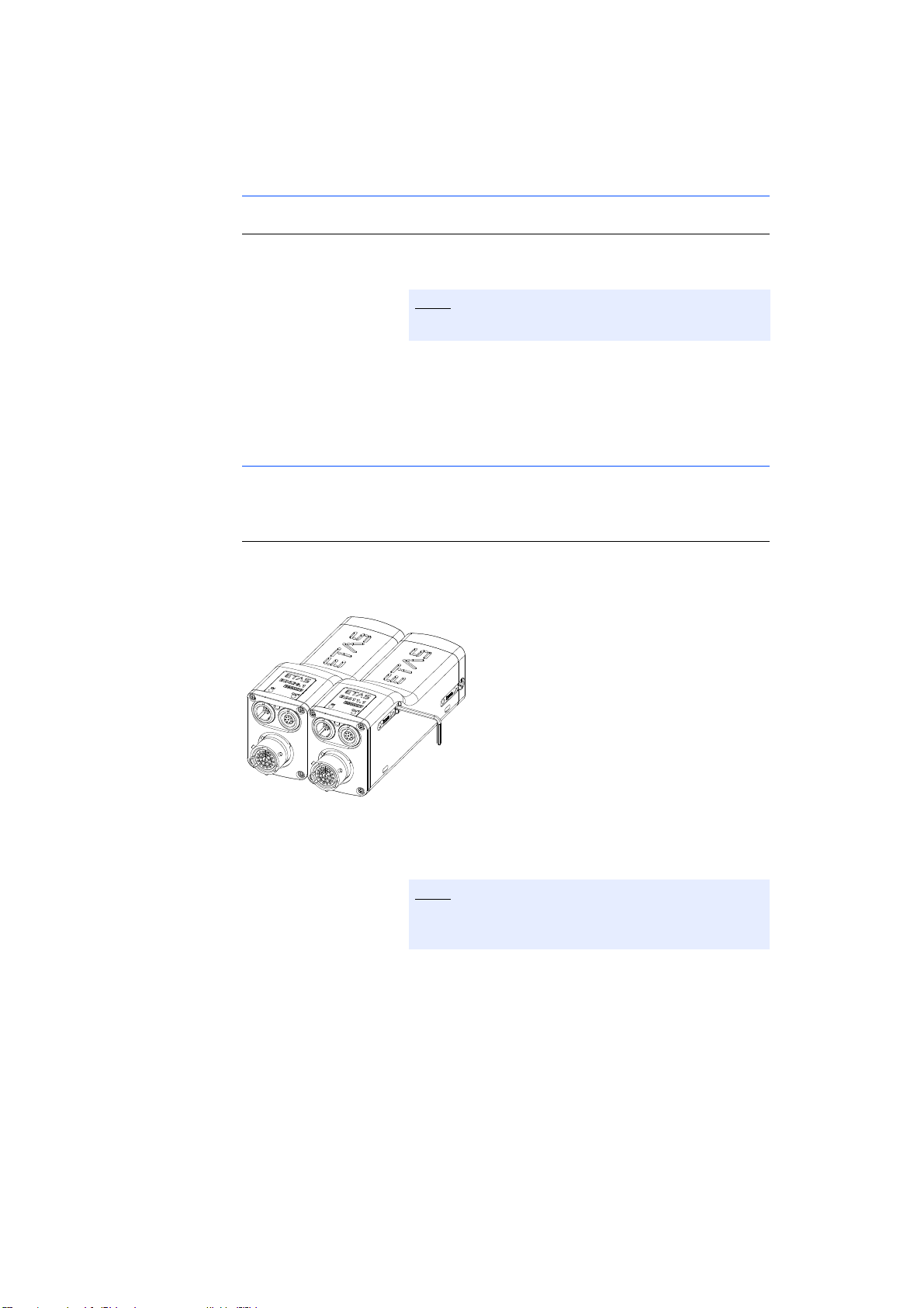
1. Position the modules to be connected in the
required order.
Both modules’ ports must point left.
2. Position the modules so that their fronts are in a
line.
3. Hold the two modules together firmly on their outer
sides.
Connecting the Modules
To connect several ES400 modules, you require a 2 mm Allen key (minimum
length 20 mm).
To connect the modules:
1. Insert the Allen key into a hexagon socket on the
right-hand side of the right-hand module.
Fig. 5-6 Connected ES400 Modules
2. Screw the two modules by turning the Allen key
clockwise as far as it will go within the module.
Screw the two modules together without getting
them off-thread!
Both modules are now connected mechanically on
one side.
3. Insert the Allen key into the other hexagon socket
of the right-hand module.
ES415.1 - User’s Guide38
Page 39
ETAS Getting Started
Note
Note
4. Screw the two modules by turning the Allen key
clockwise as far as it will go within the module.
Screw the two modules together without getting
them off-thread!
Both modules are now completely connected
mechanically.
Connecting to Other Modules
You can only successively screw additional modules, but not module blocks,
onto the right-hand side of this module.
To connect the ES400 module to other modules, you require a 2 mm Allen key
(minimum length 20 mm).
To connect to other modules:
1. Assemble other modules in accordance with the
procedure described in the section 5.2.2
on page 37.
5.2.3 Attaching ES400 Modules to Other Components Using the Integrated Assembly Elements
The integrated assembly elements of the ES400 modules can not only be used to
connect modules to each other but also to connect them to other components.
Here, you connect the ES400 module to the component using the integrated
assembly elements. Screwing the two together works in the same way as connecting several modules.
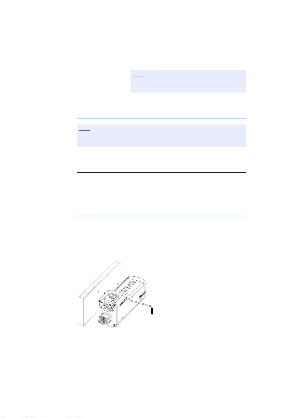
Fig. 5-7 Attaching a Module to Other Components with the Integrated
Assembly Elements
ES415.1 - User’s Guide 39
Page 40

Getting Started ETAS
Note
Note
Note
Rules on Attaching the Modules to Other Components
Observe the following rules when connecting the modules as required to other
components:
The two integrated assembly elements can only be accessed from the righthand side of the module and can only be turned using an Allen key.
You therefore have to screw the module to the other component from the
right.
You can only successively screw additional modules, but not module blocks,
onto the right-hand side of this module.
Preparing the Component
To cut the thread in the component:
1. Cut two M3 threads into the selected component.
The threads should be cut 8 mm deep.
Use the drilling template (see Fig. 5-13 on page 50).
Connecting the Module to the Component
To connect the ES400 module to the component, you require a 2 mm Allen key
(minimum length 20 mm).
To connect the module and the component:
1. Position the module to the right of the other component.
2. Align the integrated assembly elements of the module with the drill holes.
3. Insert the Allen key into a hexagon socket on the
right-hand side of the module.
4. Screw the two parts together by turning the Allen
key clockwise as far as it will go within the module.
Screw the two parts together without getting them
off-thread!
Both parts are now connected mechanically on one
side.
5. Insert the Allen key into the other hexagon socket
of the module.
ES415.1 - User’s Guide40
Page 41
ETAS Getting Started
Note
Note
6. Screw the two parts together by turning the Allen
key clockwise as far as it will go within the module.
Screw the two parts together without getting them
off-thread!
Both parts are now completely connected mechanically.
Connecting to Other Modules
You can only successively screw additional modules, but not module blocks,
onto the right-hand side of this module.
To connect the ES400 module to other modules, you require a 2 mm Allen key
(minimum length 20 mm).
To connect to other modules:
1. Assemble other modules in accordance with the
procedure described in the section 5.2.2
on page 37.
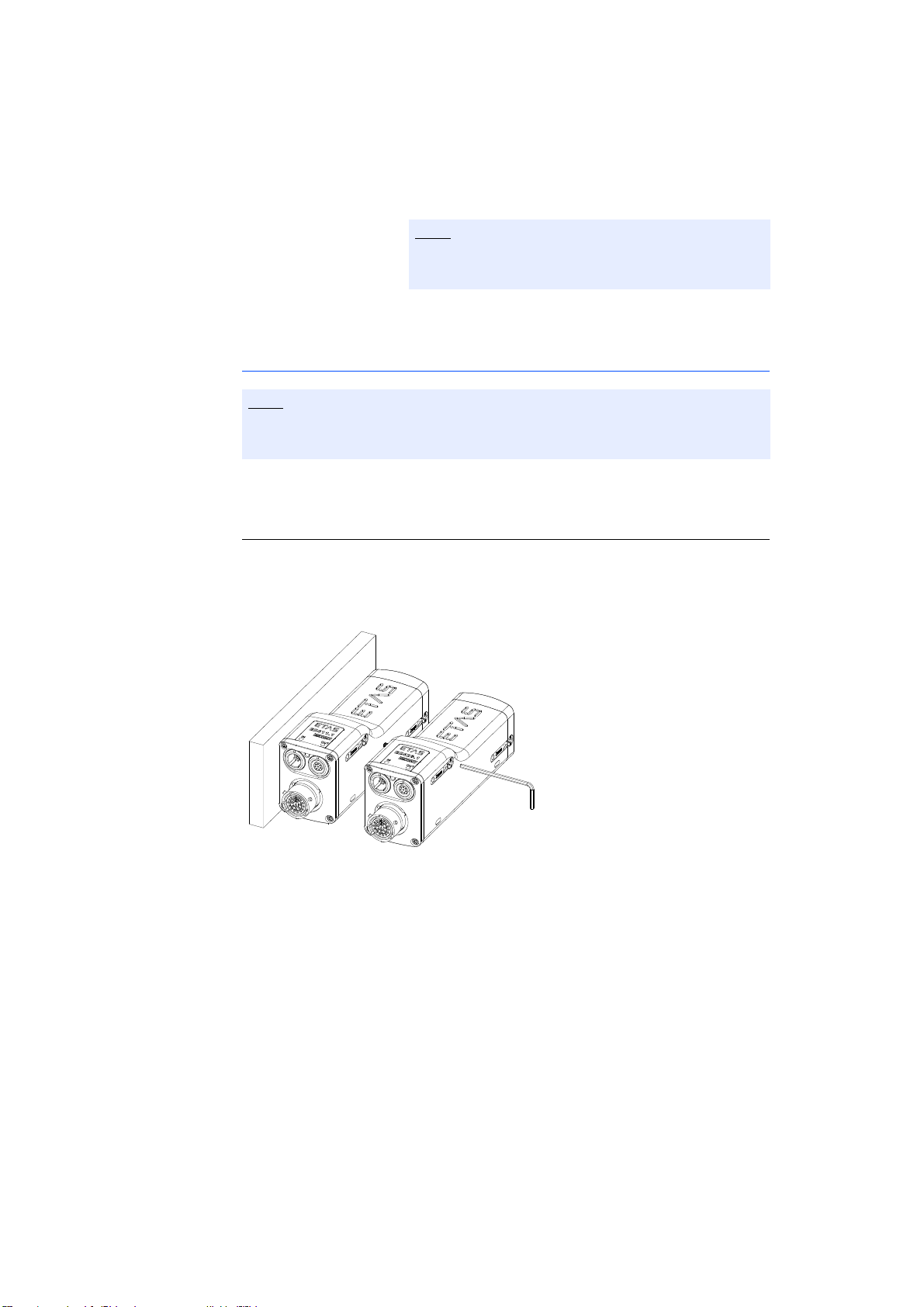
Fig. 5-8 Connecting to Other Modules
ES415.1 - User’s Guide 41
Page 42
Getting Started ETAS
Note
5.2.4 Attaching ES400 Modules on DIN Rails with the Integrated Assembly Elements
With the integrated assembly elements of the ES400 modules, you can not only
connect the modules with each other, but also with DIN rails.
For this fastening variant, you connect the ES400 module with the DIN rail using
an ES4xx angle bracket (left). The screw connection follows the principle of connecting several modules.
Fasten the ES400 modules on DIN rails with the integrated assembly elements
using the following steps:
1. Connect the module with the ES4xx angle bracket
(left).
2. Connect the module with additional modules
(as required).
3. Connect the ES4xx angle bracket with the DIN rail.
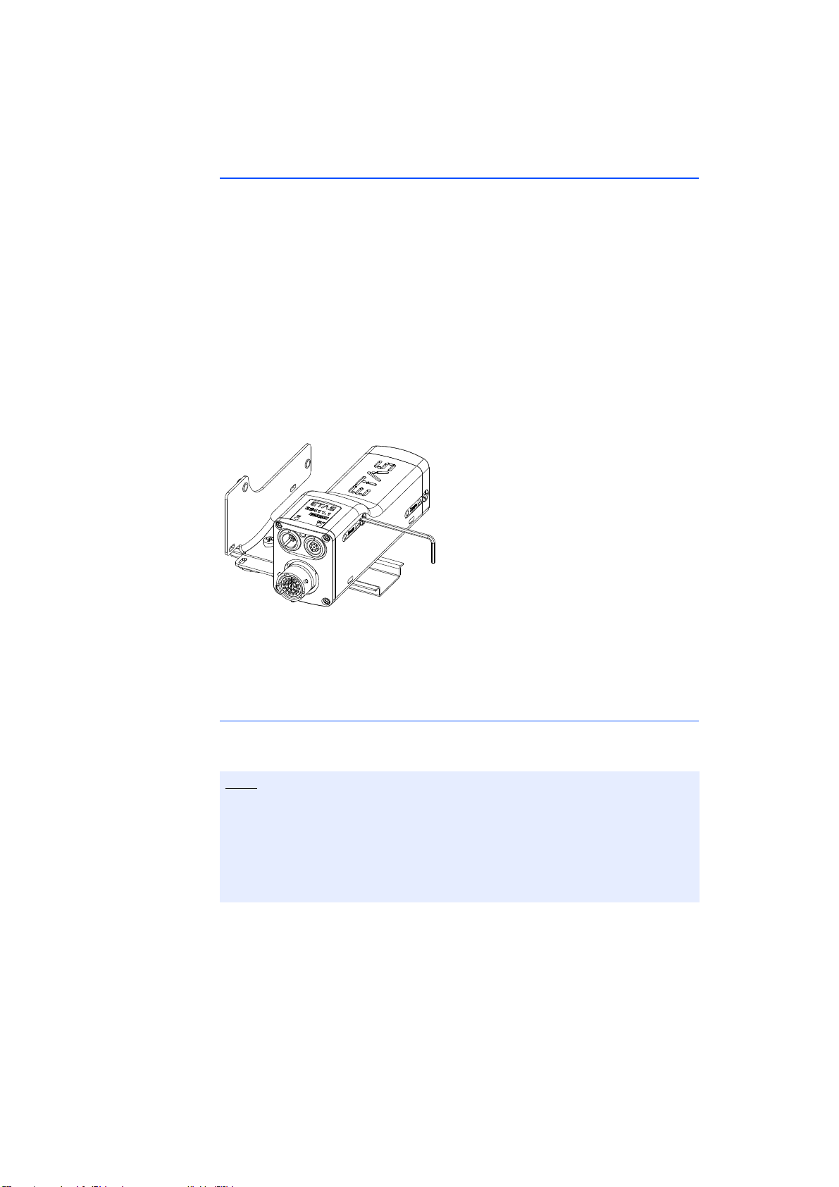
Fig. 5-9 Fastening to an ES4xx Angle Bracket (left) using the Integrated
Assembly Elements
Rules on Connecting the Modules on the DIN Rails using the ES4xx Angle Bracket
(left)
To be able to fasten the modules in the desired arrangement with the ES4xx
angle bracket (left) on DIN rails, observe the following rules:
The two integrated assembly elements are accessible only from the right side
of the module and can be rotated with a hex key.
For this reason, the module must always be screwed onto the ES4xx angle
bracket (left) from the right side.
Additional modules can only be screwed onto the right side of this module, but
not any module blocks.
ES415.1 - User’s Guide42
Page 43

ETAS Getting Started
Note
Note
Note
Connect the Module with the ES4xx Angle Bracket (left)
Connecting the ES400 module with the ES4xx angle bracket (left) requires a
2 mm hex key (minimum length 20 mm).
Connecting the module and the ES4xx Angle Bracket (left):
1. Position the module to the right of the ES4xx angle
bracket (left).
2. Align the integrated assembly elements of the module with the bores.
3. Insert the hex key in a hexagon head on the right
side of the module.
4. Screw the parts together by turning the hex key
clockwise to the stop within the module.
Screw the two parts together without canting the
threads!
Both parts are now mechanically connected on one
side.
5. Insert the hex key in the other hexagon head of the
module.
6. Screw the parts together by turning the hex key
clockwise to the stop within the module.
Screw the two parts together without canting the
threads!
Both parts are now completely connected mechanically.
Connecting with Additional Modules
Additional modules can only be screwed onto the right side of this module, but
not any module blocks.
Connecting the ES400 module with additional modules requires a 2-mm hex key
(minimum length 20 mm).
Connecting with additional modules:
1. Connect additional modules according to the procedure described in chapter 5.2.2 on page 37.
ES415.1 - User’s Guide 43
Page 44
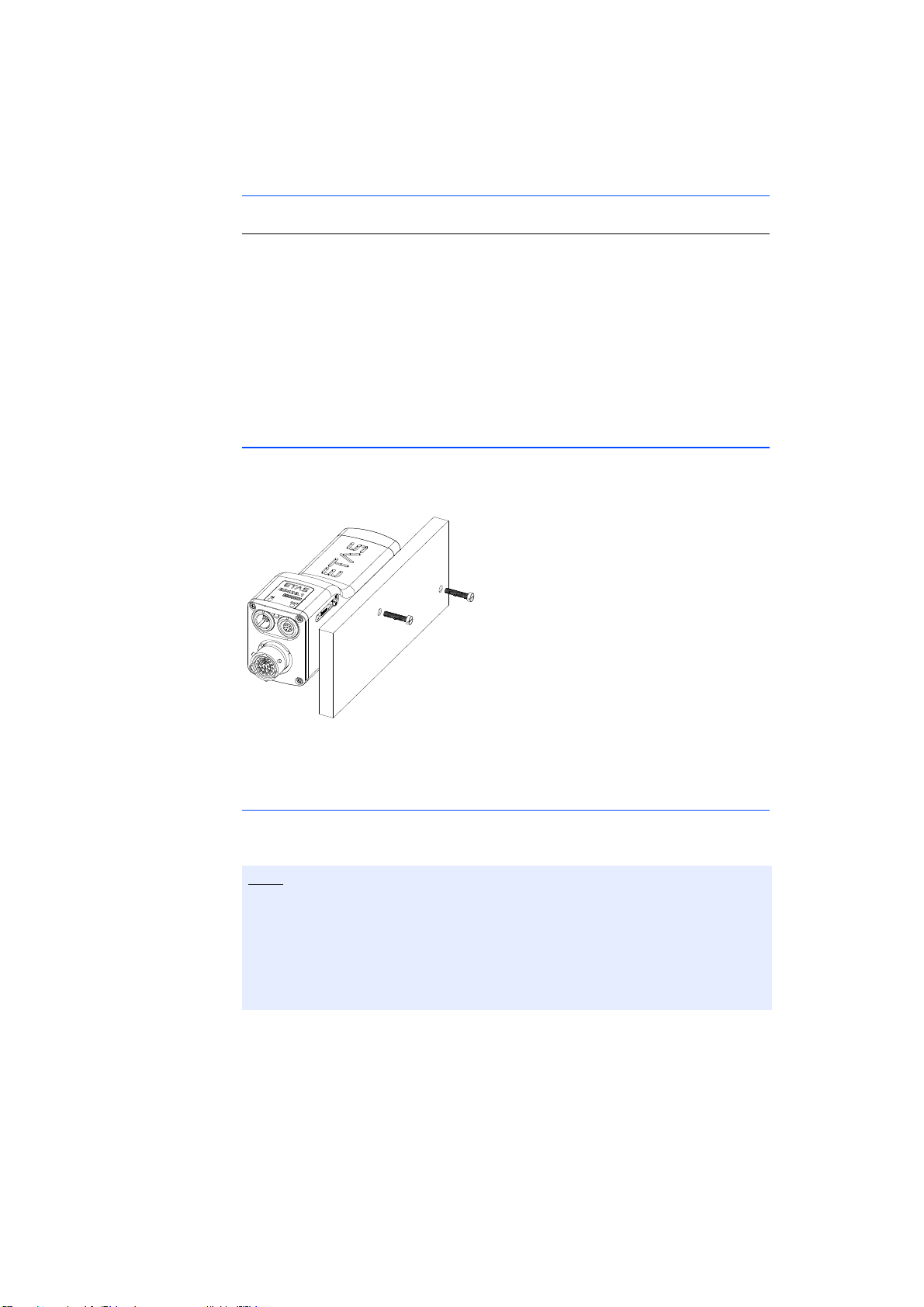
Getting Started ETAS
Note
Connecting the ES4xx Angle Bracket with the DIN Rail
Connecting the ES4xx Angle Bracket (left) with the DIN rail
1. Place the ES4xx angle bracket onto the DIN rail.
2. Insert the hooks of the ES4xx angle bracket into the
upper part of the DIN rail.
3. Engage the ES4xx angle bracket in the DIN rail by
pressing on the ES4xx angle bracket or the module.
The module connected with the ES4xx angle
bracket is fastened to the DIN rail.
5.2.5 Attaching ES400 Modules to Other Components with Screws
Here, you connect the ES400 module to the component using two additional M3
screws which are screwed into the drill holes of the component. The integrated
assembly elements of the module are not used.
Fig. 5-10 Attaching to Other Components Using Additional Screws
Rules on Attaching the Modules to Other Components
Observe the following rules when connecting the modules as required to other
components:
The two integrated threaded holes in the module are only accessible from the
right-hand side of the module.
You therefore have to screw the other component onto the module from the
right.
Once the module is screwed to the other component, you cannot screw any
further modules to this one.
ES415.1 - User’s Guide44
Page 45

ETAS Getting Started
Note
Note
Note
Note
Preparing the Component
The pivot of the integrated assembly element can be screwed around 6 mm out
of the module.
To drill the openings in the component:
1. Drill two holes in the selected component.
Use the drilling template to prepare the component
(see Fig. 5-13 on page 50).
Connecting the Module to the Component
To connect the ES400 module to the component, you need two screws M3 and
a screwdriver.
To connect the module and the component:
1. Position the module to the right of the other component.
2. Align the threaded drill holes of the integrated
assembly elements on the right-hand side of the
module to the openings in the component.
3. Insert one screw into a hole in the component.
4. Screw the screw from the right-hand side of the
component into the module.
Screw the two parts together without getting them
off-thread!
Both parts are now connected mechanically on one
side.
5. Insert the other screw into the other hole in the
component.
6. Screw the screw from the right-hand side of the
component into the module.
Screw the two parts together without getting them
off-thread!
Both parts are now completely connected mechanically.
ES415.1 - User’s Guide 45
Page 46
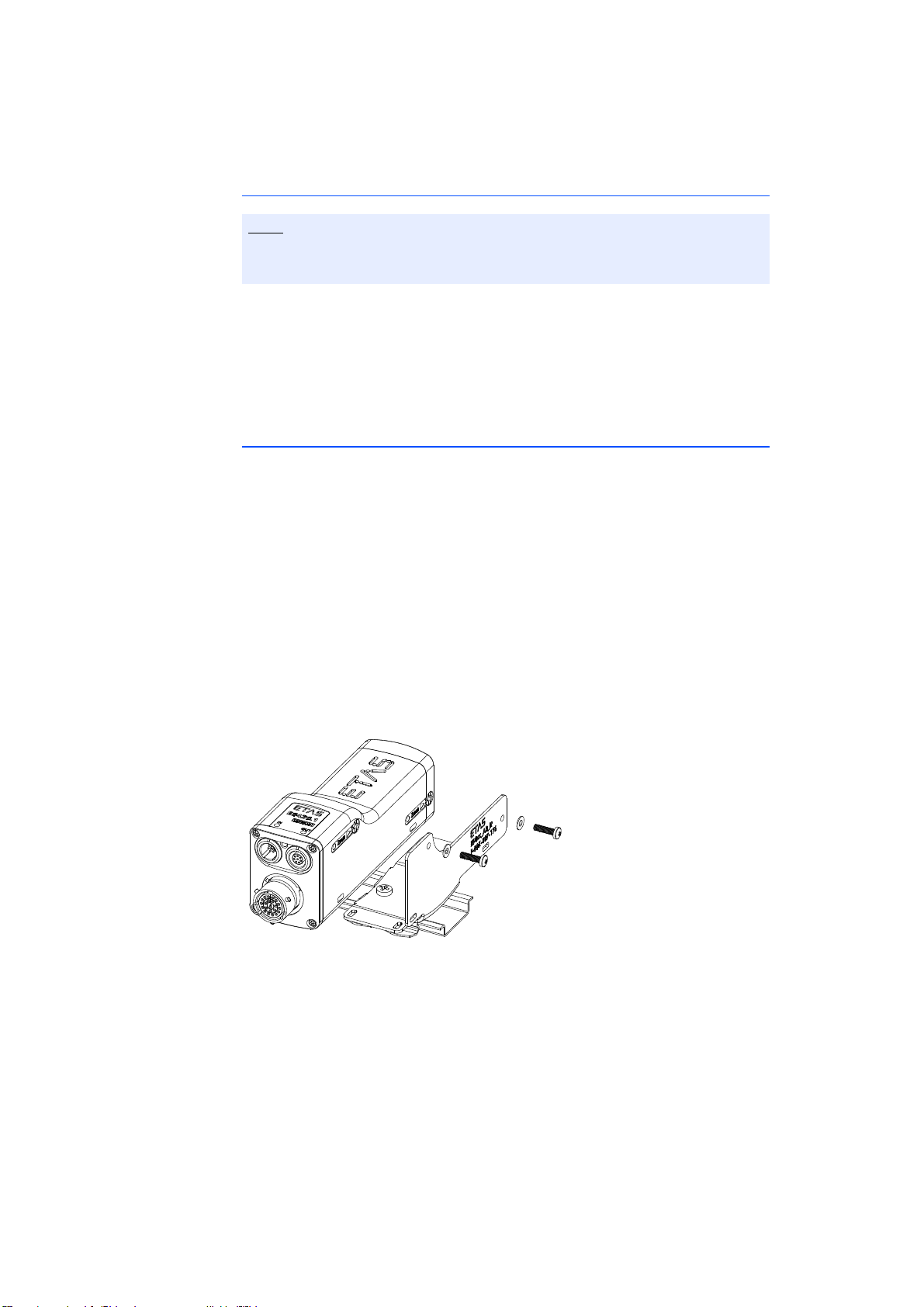
Getting Started ETAS
Note
Connecting to Other Modules
If a module has been screwed to the other component, no other modules can
be screwed to this module component connection.
You can attach several ES400 modules to the other component using the
method described in this chapter if you first connect all modules to be installed
with each other step by step (see section 5.2.2 on page 37). The module on the
extreme right of the module block is connected to the other component like an
individual module - using screws.
5.2.6 Attaching ES400 Modules on DIN Rails using Screws
With the integrated assembly elements of the ES400 modules, you can not only
connect the modules with each other, but also with DIN rails.
For this fastening variant, you connect the ES400 module with the DIN rail using
an ES4xx angle bracket (right) and two additional M3 screws inserted through
their bores. The integrated assembly elements of the module are not used.
Fasten the ES400 modules on DIN rails with the integrated assembly elements
using the following steps:
1. Connect the module with additional modules
(as required).
2. Connect the module with the ES4xx angle bracket
(right).
3. Connect the ES4xx angle bracket with the DIN rail.
Fig. 5-11 Fastening on DIN Rails with Additional Screws
ES415.1 - User’s Guide46
Page 47

ETAS Getting Started
Note
Note
Note
Rules on Connecting the Modules on the DIN Rails using the ES4xx Angle Bracket
(right)
To be able to fasten the modules in the desired arrangement with the ES4xx
angle bracket (right) on DIN rails, observe the following rules:
The two integrated thread bores in the module for accepting the screws can be
accessed only from the right side of the module.
For this reason, the ES4xx angle bracket (right) must always be screwed onto
the module from the right side.
If the module is screwed onto the ES4xx angle bracket (right), no additional
modules can any longer be screwed onto this module.
Preparing the Component
The pin of the integrated assembly element can be screwed out of the module
by approximately 6 mm.
Connecting the Module with the ES4xx Angle Bracket (right)
To connect the ES400 module with the ES4xx angle bracket (right) requires two
M3 screws, two washers and a screwdriver.
Connecting the module and the ES4xx Angle Bracket (right):
1. Position the module to the left of the ES4xx angle
bracket (right).
2. Align the thread bores of the integrated assembly
elements on the right side of the module with the
through bores of the ES4xx angle bracket (right).
3. Insert one screw through the bore of the ES4xx
angle bracket (right).
4. Fasten the screw with the module from the right
side of the ES4xx angle bracket.
Screw the two parts together without canting the
threads!
Both parts are now mechanically connected on one
side.
5. Insert the other screw through the other bore of the
ES4xx angle bracket (right).
ES415.1 - User’s Guide 47
Page 48

Getting Started ETAS
Note
Note
6. Fasten the screw with the module from the right
side of the ES4xx angle bracket.
Screw the two parts together without canting the
threads!
Both parts are now completely connected mechanically.
Connecting with Additional Modules
If a module is screwed onto the other component, no additional modules can
be screwed onto this module-component connection.
Several ES400 modules can be fastened to the other component with the connection type described in this chapter if you connect all modules to be attached
first with each other step by step (see chapter 5.2.2 on page 37). The module
which is the furthest to the right of the module block is subsequently connected
with the ES4xx angle bracket (right) as a single module and fastened to the DIN
rail using screws.
Connecting the ES4xx Angle Bracket with the DIN Rail
Connecting the ES4xx Angle Bracket (right) with the DIN rail
1. Place the ES4xx angle bracket onto the DIN rail.
2. Insert the hooks of the ES4xx angle bracket into the
upper part of the DIN rail.
3. Engage the ES4xx angle bracket in the DIN rail by
pressing on the ES4xx angle bracket or the module.
The module connected with the ES4xx angle
bracket is fastened to the DIN rail.
ES415.1 - User’s Guide48
Page 49
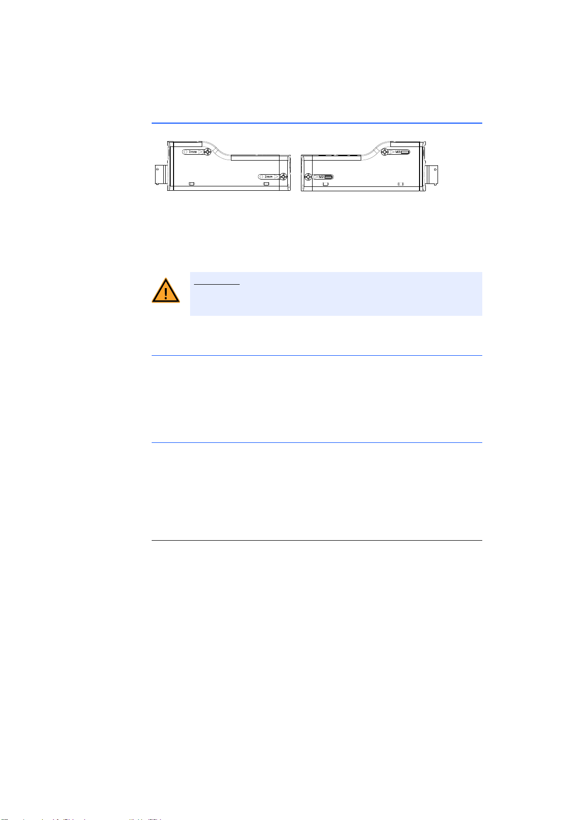
ETAS Getting Started
CAUTION!
5.2.7 Attaching ES400 Modules to Other Components Using Cable Fasteners
Fig. 5-12 Openings for Cable Fasteners in ES400 Modules
Every module base has openings for two cable fasteners each on the right- and
left-hand side (see Fig. 5-12 on page 49). Just use cable fasteners to quickly
attach the modules to other components in the test environment in the immediate proximity of the measuring points.
When assembling the modules, observe the admissible temperature
range of the cable fasteners used!
Attaching ES400 Modules to Other Components Using Cable Fasteners
With this method of attachment, you connect the ES400 module or ES400 module blocks to the component using additional cable fasteners inserted through
the openings of the modules. The integrated assembly elements of the module
are not used.
Fastening ES400 Modules on DIN Rails using Cable Fasteners
For this fastening variant, the ES400 module or ES400 module blocks are connected with an ES4xx angle bracket (right) or with an ES4xx angle bracket (left)
using additional cable fasteners inserted through the breakouts of the module.
The integrated assembly elements of the module are not used.
The modules fastened to the ES4xx angle bracket are subsequently attached to
the DIN rail.
Connecting the ES4xx Angle Bracket with the DIN rail
1. Place the ES4xx angle bracket onto the DIN rail.
2. Insert the hooks of the ES4xx angle bracket into the
upper part of the DIN rail.
3. Engage the ES4xx angle bracket in the DIN rail by
pressing on the ES4xx angle bracket or the module.
The module connected with the ES4xx angle
bracket is fastened to the DIN rail.
ES415.1 - User’s Guide 49
Page 50
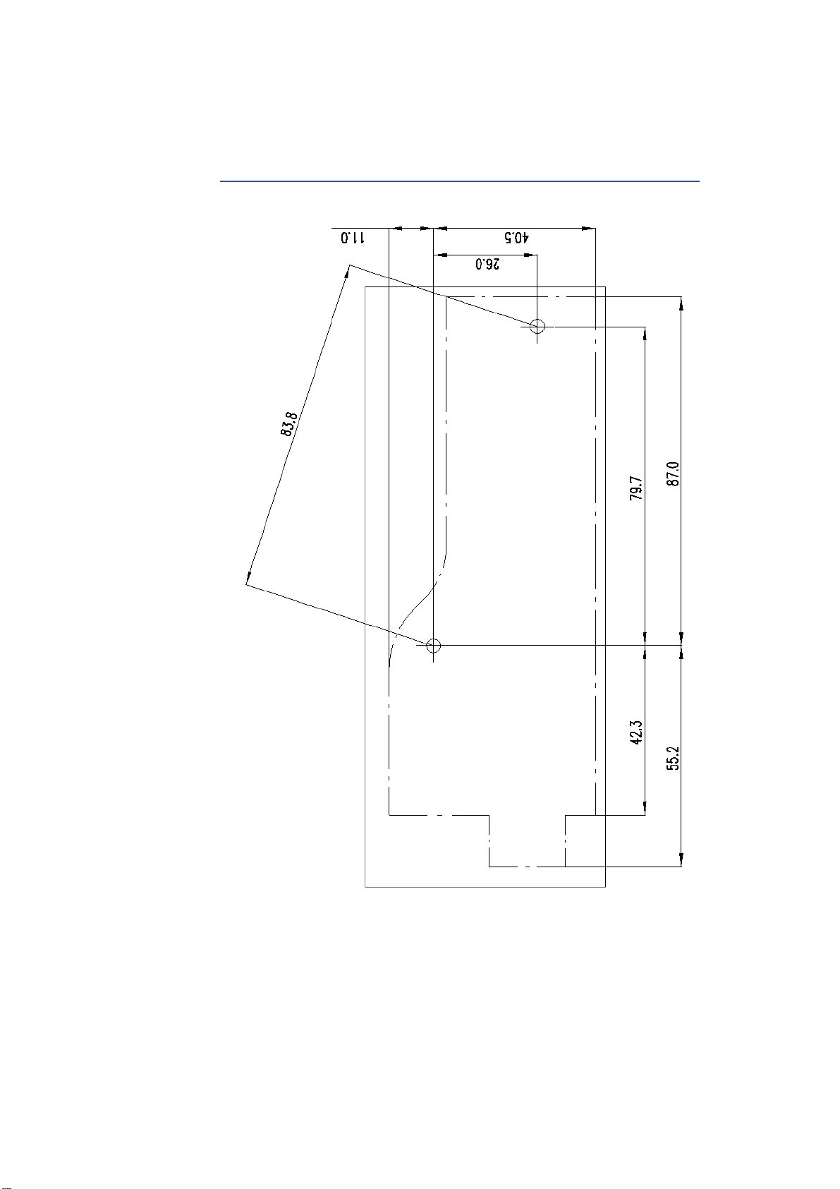
Getting Started ETAS
5.3 Drilling Template
Fig. 5-13 Drilling Template
ES415.1 - User’s Guide50
Page 51
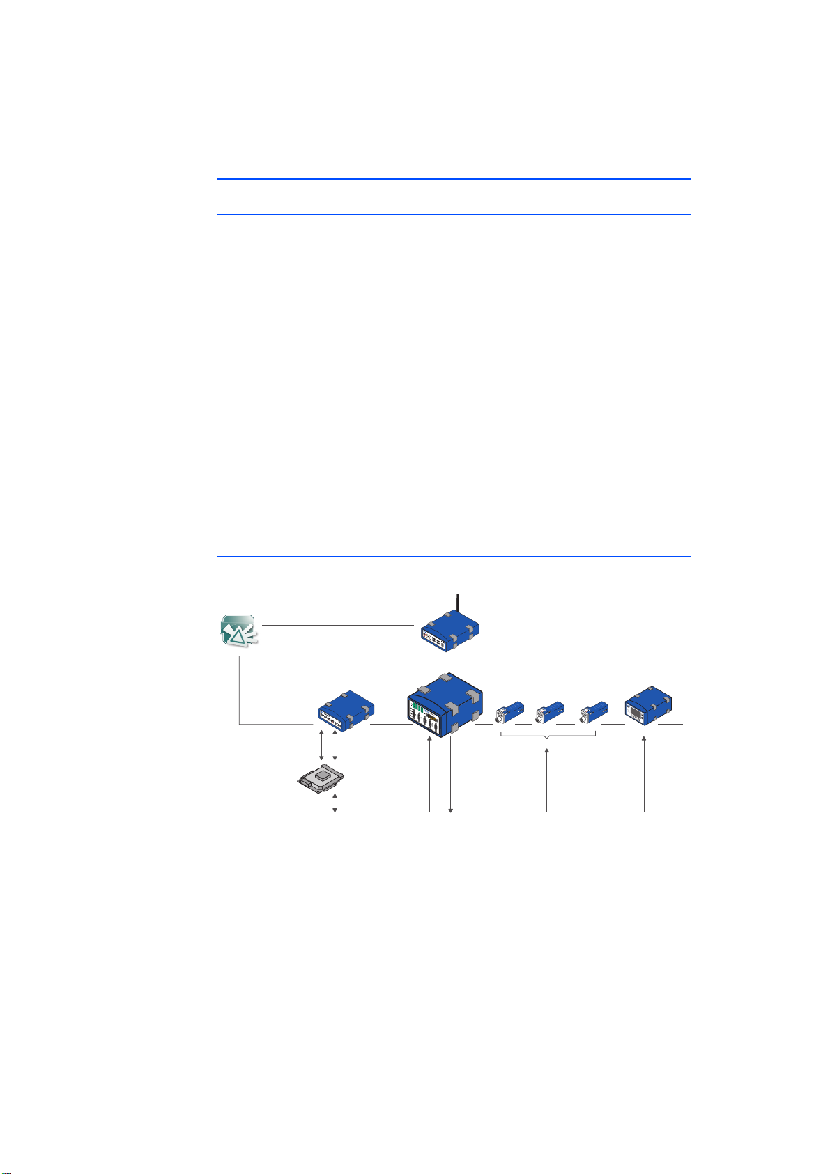
ETAS
5.4 Applications
5.4.1 General
The modules ES4xx/ES63x/ES93x can be used for the following applications, individually or as part of a daisy chain module chain:
• Measuring and calibrating with INCA
• Rapid Prototyping with INTECRIO (with ES910.3 Prototyping Module or
with RTPRO-PC).
Additional ECU and bus interface modules as well as measuring modules are
networked with each other via Ethernet and connected with the daisy chain
module chain.
The measuring setup can be supplemented with a drive recorder to record all of
the data acquired by the connected modules. The drive recorder ES720.1 supports the simultaneous recording of different measurements (multi-recording).
The data are stored in the ASAM standard format MDF (Measure Data Format).
They can be conveniently evaluated using the Measure Data Analyzer MDA from
ETAS and easily be compared with INCA reference measurements. The drive
recorder ES720.1 can automatically transfer the recorded measure data
encrypted and compressed via LAN, WLAN or wireless radio to customer-specific
data servers.
5.4.2 ES415.1 with additional ETAS Modules (MC Application)
Experimental
Environment
INCA + EIP
MC:
Latency Output
app. 300 ms
ETK
ECU
Interface Module
ES59x
CAN, LIN,
FlexRay
Drive Recorder
ES720
Multi I/O-Module
ES930
16
Inputs
Vehicle, Test Bench, Motor, ...
14
Outputs
6
Halfbridges
Micro Measurement Modules
ES4xx
Fig. 5-14 ES415.1 with additional ETAS Modules for MC Applications
The ETAS Daisy Chain concept enables a simple network architecture since only
the ES415.1 or the first module of the module chain is connected with the PC or
with the "ETH" port of the ES59x.1.
Additional bus analysis functions on the CAN, LIN and FlexRay buses as well as
(X)ETK bypass applications with measuring and calibrating can be made accessible with ES59x modules.
Voltage,
Temperature,
Lambda,
Counter,
1 Type per Module
Lambda Module
ES63x
Lambda
ES415.1 - User’s Guide 51
Page 52
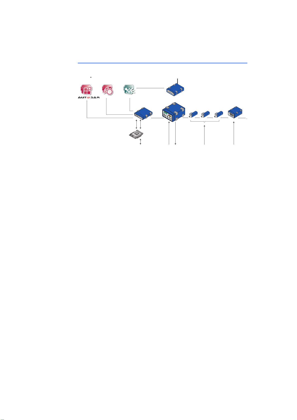
5.4.3 ES415.1 with additional ETAS Modules (Rapid Prototyping Application)
Drive Recorder
ES720
Multi I/O-Module
ES930
ECU
ETK
CAN, LIN,
FlexRay
Lambda
Lambda Module
ES63x
16
Inputs
14
Outputs
6
Halfbridges
Voltage,
Temperature,
Lambda,
Counter, ...
1 Type per Module
Micro Measurement Modules
ES4xx
Experimental
Environment
INCA + EIP
Vehicle, Test Bench, Motor, ...
Rapid Prototyping System
ES910, ES920, ES921
HW and SW
Integration and
Configuration
INTECRIO, ASCET-RP
Code
ASCET,
Simulink or
C-Code
RP: Latency
Input/ Output
app. 2 ms
Fig. 5-15 ES415.1 with ES910.3 and additional ETAS Modules for Rapid Proto-
typing Applications
The concept of the ES4xx/ES63x/ES93x product family to install the modules as
close as possible to the sensors, the chain the modules with each other, and to
connect only the first module of this chain with the ES910.3 or the RTPRO-PC,
enables a simple network architecture.
The combination of ES910.3 or PTPRO-PC with daisy chain modules can process
information from sensors and control actuators in the Rapid Prototyping model.
From the Rapid Prototyping model, it is possible to access the connected modules
whose signals are processed directly in the Rapid Prototyping model.
The ES910.3 or RTPRO-PC can access all customary ECU interfaces (ETK, XETK,
CAN, LIN, FlexRay) and calculate the new control functions in the bypass.
Parallel to the bypass RP functionality, all control and diagnostics parameters as
well as all measure signals of the connected ECU can be accessed with INCA. In
addition, INCA/INCA-EIP offers access to all bypass and model sizes created in the
ES910.3 Prototyping Module.
ETAS
ES415.1 - User’s Guide52
Page 53
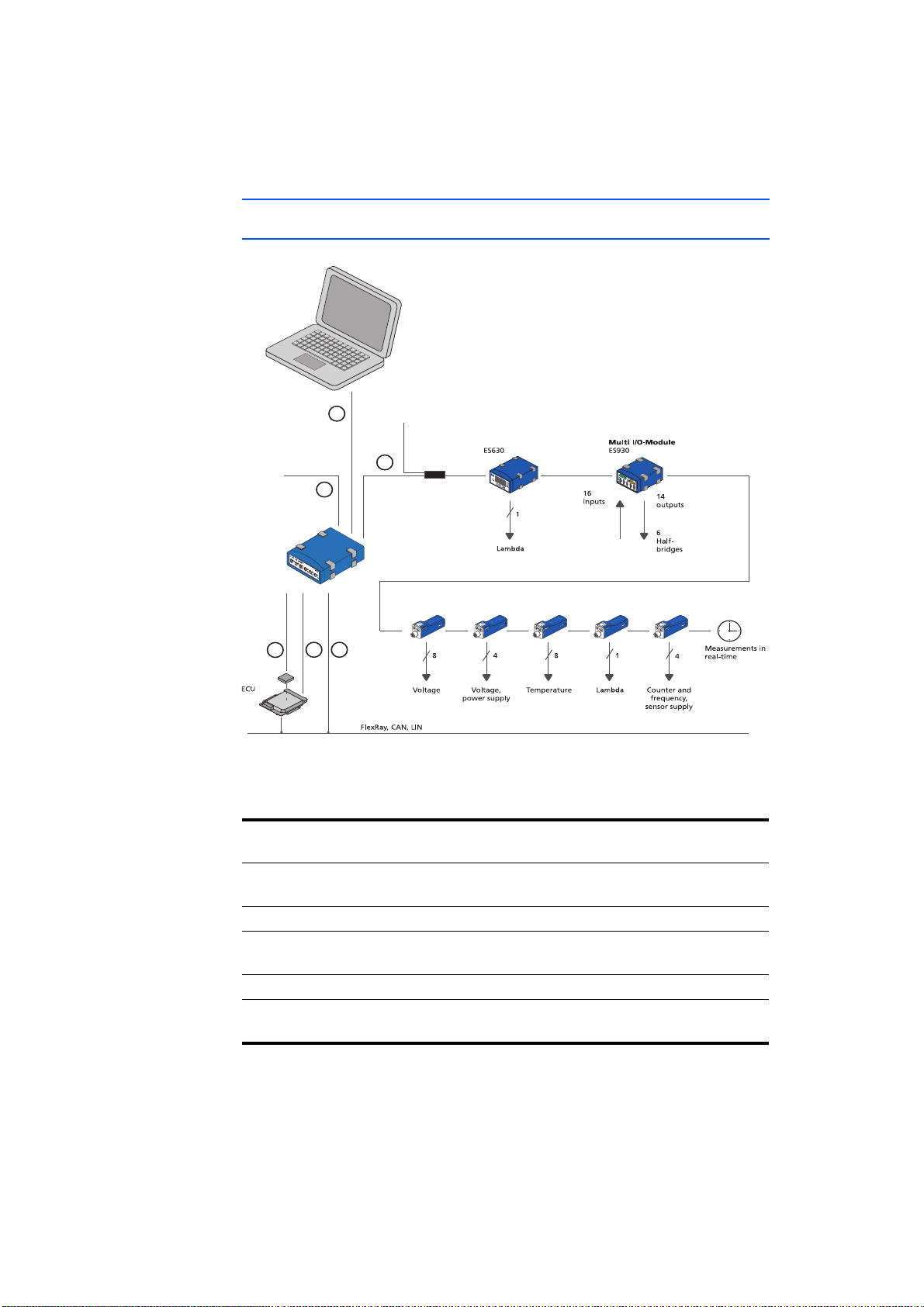
ETAS
Power Supply
Daisy Chain Modules
4
3
5
2
1
ETK
CAN
FLX
6
ES411
ES413
ES415
ES595
ETH
Power Supply
ES410
ES420
ES421
ES430
ES432
ES441
5.5 Wiring Examples
5.5.1 ES400 Modules with additional ETAS Modules (Measurement and Calibration)
Fig. 5-16 ES400 Modules with add. ETAS Modules (Measurement and Calibra-
tion)
Cable in
Function Order name
Fig. 5-16
1 Power supply cable CBP120,
CBP1205
2 Host connection cable CBE100
3 Power supply and Ethernet cable Daisy Chain
modules
4 ETK connection cable CBM150
5, 6 CAN/LIN/FLX connection cable (CAN/LIN/FLX
ES415.1 - User’s Guide 53
combined)
CBEP430,
CBEP4305
CBCFI100
Page 54
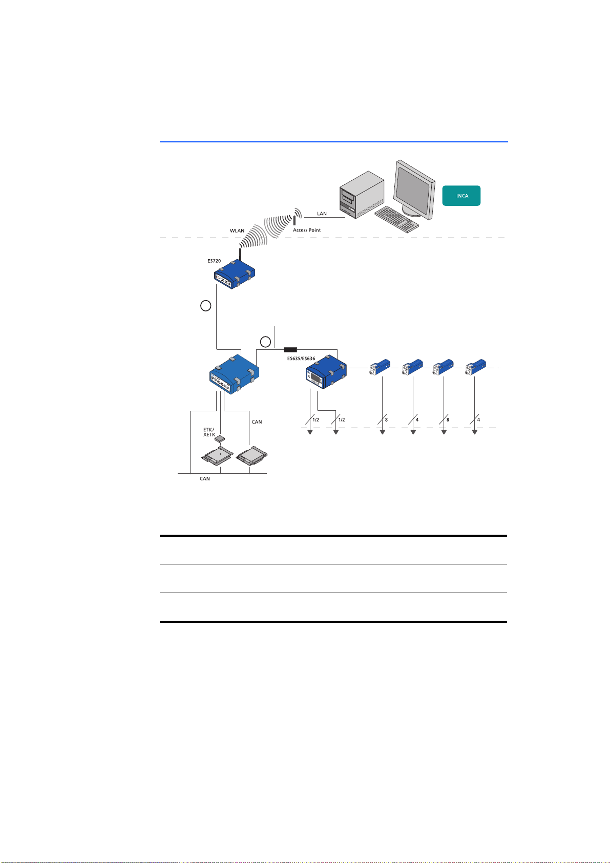
ETAS
5.5.2 ES400 Modules with additional ETAS Modules and Drive Recorder (Measurement and Calibration)
Vehicle
Drive Recorder
10/100 MBit/s
1
Ethernet
Power Supply
Daisy Chain Modules
2
ES59x
ECUECU
Daisy Chain Measurement Modules
ES410
Ambient/
Lambda Voltage Sensor
Exhaust
Pressure
ES411
ES413
ES415
Voltage
ES420
ES421
Temperature
ES441
Frequency,
Counter Results,
Times
Fig. 5-17 ES400 Modules with additional ETAS Modules and Drive Recorder
(Measurement and Calibration)
Cable in
Function Order name
Fig. 5-17
1 ES520-, ES59x-, ES6xx-, ES1120- or ES1135-
CBE130, CBE140
Ethernet cable
2 Power supply and Ethernet cable Daisy Chain
modules
CBEP430,
CBEP4305
ES415.1 - User’s Guide54
Page 55
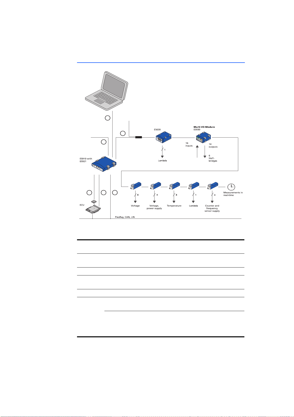
ETAS
5.5.3 ES400 Modules with ES910.3 (Rapid Prototyping)
6
Power Supply
Daisy Chain Modules
3
ES410
ES411
ES413
ES415
ES420
ES421
ES430
ES432
ES441
Power Supply
4
ETK
CAN
2
1
CAN
5
Fig. 5-18 ES400 Modules with ES910.3 (Rapid Prototyping)
Cable in
Function Order name
Fig. 5-18
1 Power supply cable CBP120,
CBP1205
2 PC connection cable CBE200
3 Power supply and Ethernet cable Daisy Chain
modules
CBEP430,
CBEP4305
4 ETK connection cable CBM150
5, 6 CAN/LIN/FLX connection cable (CAN/LIN/FLX
CBCFI100
combined) at ES910.3, at ES921.1
CAN connection cable (CAN only), at ES910.3,
at ES921.1
CBAC130,
CBAC140,
CBAC150,
CBCX130
ES415.1 - User’s Guide 55
Page 56
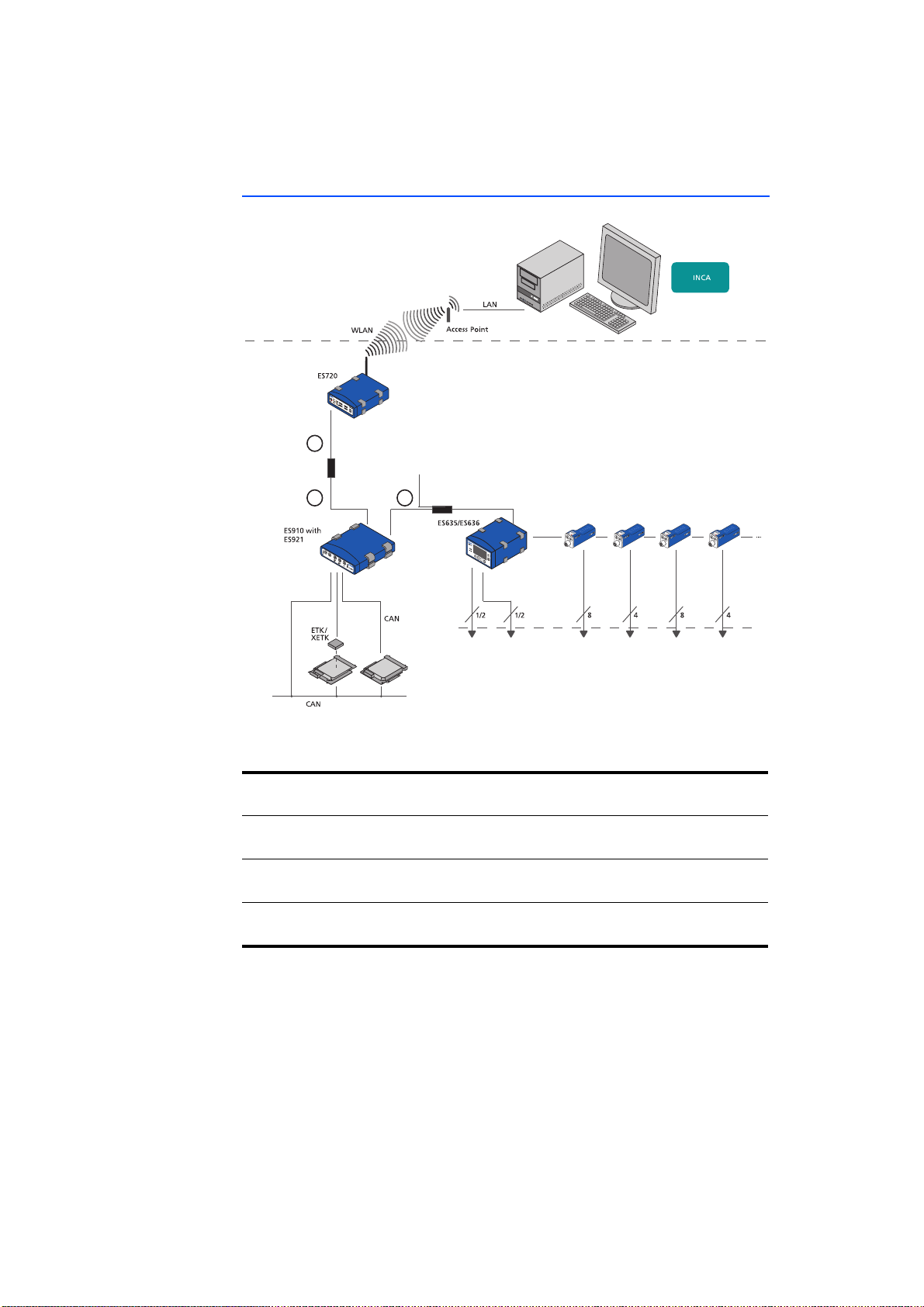
5.5.4 ES400 Modules with ES910.3 and Drive Recorder (Rapid Prototyping)
Vehicle
Drive Recorder
10/100 MBit/s
1
Ethernet
Power Supply
Daisy Chain Modules
ETAS
1 GBit/s
2
Ethernet
ECUECU
3
Daisy Chain Measurement Modules
Ambient/
Lambda
Exhaust
Pressure
ES410
Voltage Sensor
ES411
ES413
ES415
Voltage
ES420
ES421
Temperature
ES441
Frequency,
Counter Results,
Times
Fig. 5-19 ES400 Modules with ES910.3 and Drive Recorder (Rapid Prototyping)
Cable in
Function Order name
Fig. 5-19
1 Ethernet adapter cable (100 Mbit/s) CBAE330 (con-
nected to cable 2)
2 Ethernet connection cable(1 Gbit/s) CBE230 (con-
nected to cable 1)
3 Power supply and Ethernet cable Daisy Chain
modules
CBEP430,
CBEP4305
ES415.1 - User’s Guide56
Page 57
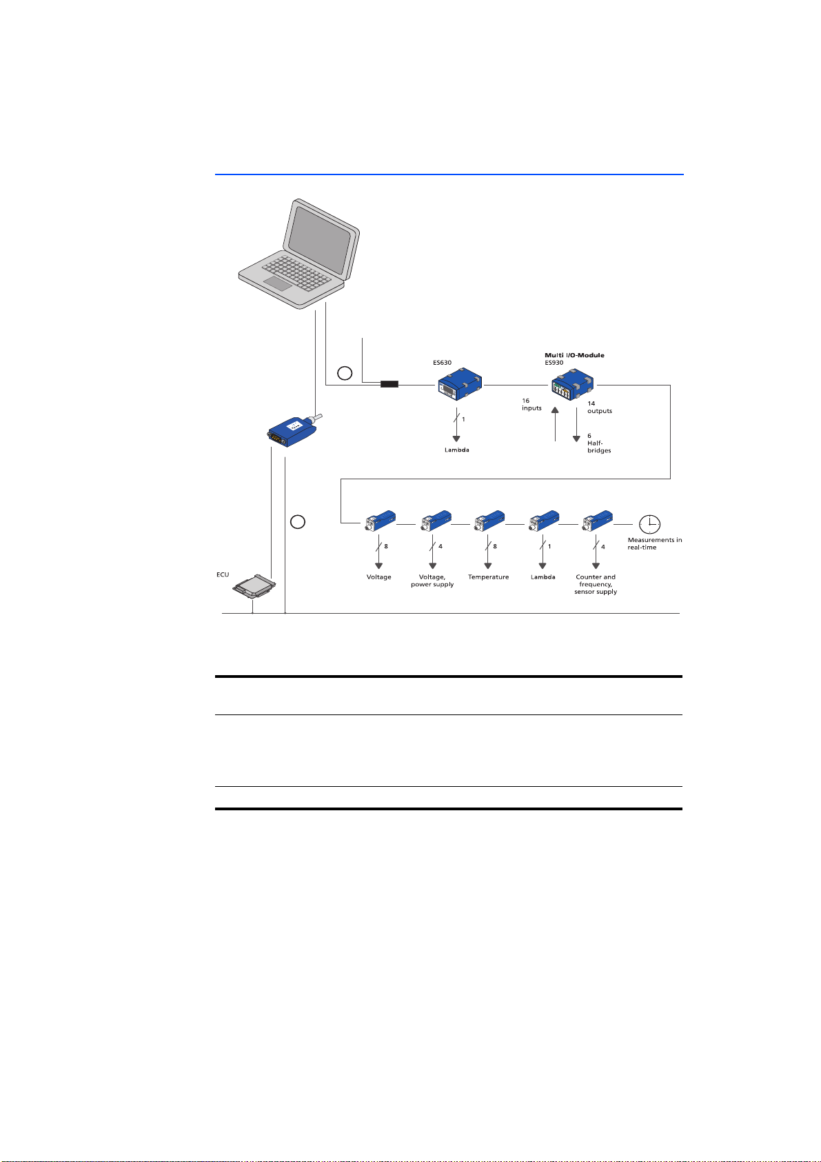
ETAS
5.5.5 ES400 Modules with ETAS RTPRO-PC (Rapid Prototyping)
Ethernet
USB2
ES581.4
Power Supply
Daisy Chain Modules
1
CAN
ES413
ES410
2
CAN
ES415
ES420
ES421
ES430
ES432
ES441
ES411
Fig. 5-20 ES400 Modules with ETAS RTPRO-PC (Rapid Prototyping)
Cable in
Function Order name
Fig. 5-20
1 Power supply and Ethernet cable PC and Daisy
Chain modules
CBEP410,
CBEP4105,
CBEP415,
CBEP4155
2 CAN and FlexRay Y-interface cable CBCF100
ES415.1 - User’s Guide 57
Page 58

5.6 Wiring
The ports may be wired in any order. Special connecting cables are available and
can be ordered separately. An overview is contained in the chapter "Cables and
Accessories" on page 85.
5.6.1 “Sensor” Port
To connect the sensors with the ES415.1, you can use different standard and
adapter cables as well as signal conditioning cables. Detailed information about
the cables offered by ETAS is located in chapter "Cable for the Connection "Sensor"" on page 95 and in the user's guides of the Signal Conditioning Cables.
Standard and Adapter Cable
• Cable CBAV411.1
You can customize the open connection of cable CBAV411.1 and adapt it
to the specific plug connector system of your measuring setup.
• Cable CBAV400.1
If you replaced modules with BNC cabling with ES415.1 modules in your
measuring setup, the use of these adapter cables enables you to continue
using the existing cabling of your measuring setup.
• Cable CBAV413.1
If you replaced IPETRONIK M-SENS modules with ES415.1 modules in your
measuring setup, the use of these adapter cables enables you to continue
using the existing cabling of your measuring setup.
Signal Conditioning Cable
ETAS
• CBN400.1 Isolating Measurement Probe
High-voltage cable, four input channels for voltages up to +/-1000 V DC
and isolation up to +/-1000 V DC
• CBN401.1 Isolating Measurement Probe
High-voltage cable, four input channels for voltages up to +/-10 V DC and
isolation up to +/-1000 V DC
• CBN41x.1 Current Probe
• CBN42x.1 Sensor Cable Providing Bipolar Sensor Supply
• CBN43x.1 Temperature Sensor Connection Cable
To wire the ES415.1 with the sensors
1. If there is a protective cap at the "Sensor" port,
remove it.
2. Connect the sensor cable to the “Sensor” port of
the ES415.1.
3. Connect the sensors and transducers to the ports of
the sensor cables of the ES415.1.
4. For your application program, jot down the assignment of the sensors to the inputs of the ES415.1 in
accordance with the wiring of the test set-up.
ES415.1 - User’s Guide58
Page 59
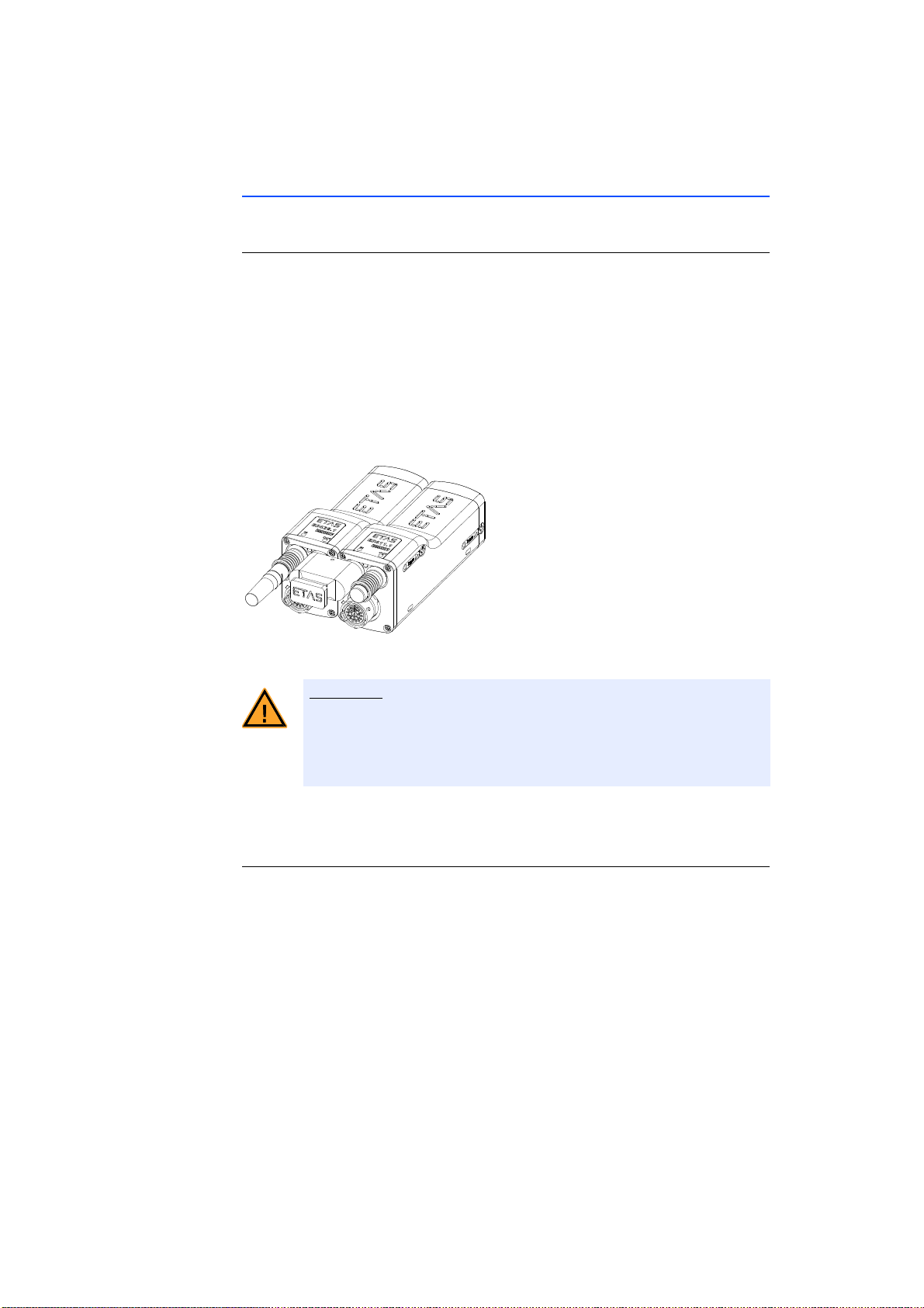
ETAS
CAUTION!
5.6.2 Daisy Chain Ports (“IN”, “OUT”)
Wiring goes from the first module towards the end of the module chain.
To wire the first module with the following module
1. Connect an Ethernet cable to the “OUT” port of
the first module.
2. Connect the Ethernet cable to the “IN” port of the
next module.
or
• If two modules are connected mechanically, connect their adjacent “IN” and “OUT” ports to the
ES4xx_BRIDGE.
The ports of the modules or the ES4xx_BRIDGE can be damaged!
Screw the two modules together without getting them off-thread as
far as it will go within the module.
3. Continue to wire or connect further modules as
described above.
To wire the first module with the PC and the power supply
1. Connect the combined Ethernet and power supply
cable to the “IN” port of the ES415.1.
2. Connect the RJ-45 connector to the free Ethernet
interface port of your PC.
3. Connect the supply voltage connector of the combined Ethernet and power supply cable to the
desired power supply.
Note the color coding of the connectors.
ES415.1 - User’s Guide 59
Page 60

To wire the module chain with additional current feeding
1. End the module chain after the last module whose
power supply is still guaranteed in the entire operational range.
2. Connect the combined Ethernet and power supply
cable to the “OUT” port of the ES415.1 of the last
module of the chain towards the PC.
3. Connect the combined Ethernet and power supply
cable to the “IN” port of the ES415.1 of the next
module towards the end of the chain.
4. Connect the supply voltage connector of the combined Ethernet and power supply cable to the
desired power supply.
Note the color coding of the connectors.
ETAS
ES415.1 - User’s Guide60
Page 61

ETAS Troubleshooting Problems
6 Troubleshooting Problems
This chapter contains information on the following topics:
• "LED Displays" on page 61
• "Troubleshooting ES415.1 Problems" on page 61
• "Problems and Solutions" on page 64
6.1 LED Displays
Please observe the LEDs which provide information on the functions of the interface and the ES415.1 (see the chapter "LED" on page 18) to be able to judge the
operational state of the ES415.1 as well as troubleshooting measures.
6.2 Troubleshooting ES415.1 Problems
The following table lists some of the possible problems with a remedy.
If you have any further questions, please contact our Customer Support (see
chapter 10 on page 108).
Problem Diagnostic Questions Possible Solutions
The application
program cannot
find any ETAS
Daisy Chain modules.
Are all modules’ LEDs flashing green?
Did you configure the network card correctly?
Did you install the required
firmware on the module?
Did you install the application software required?
Power supply Check that your power supply and test
Is the hardware connected to
the PC?
Are the modules in the module chain connected correctly?
Check that the function for automatic
change to energy saving mode on your
PC Card has been disabled
this function.
INCA, Config Tool and HSP operation:
Check that your network card has been
configured in accordance with section
6.3 on page 64.
Stand-alone operation:
Check that the IP address used belongs
to your IP subnetwork and has been
entered in the A2L file.
Check with HSP whether the required
firmware is installed on the module.
Check that the application software
installed on your PC corresponds to the
requirements listed in section 7.7.2
on page 76.
setup correspond to the requirements
listed in section 4.5 on page 31.
Check that the wiring is undamaged.
Check that the wiring is undamaged.
1)
. Disable
ES415.1 - User’s Guide 61
Page 62

Troubleshooting Problems ETAS
Problem Diagnostic Questions Possible Solutions
Measurement does
not start.
Data is lost during
data transfer.
Are you being prompted to
carry out an update in the
INCA-Monitorlog or in the
Config-Tool?
Is there no data from the
module?
You are using the ES4xx Configuration Tool and the module is supplying no data?
Is the module supplying
usable data?
Are you using WLAN in your
test setup?
Are you using the correct
type of network card in your
laptop?
Are you operating the ETAS
Daisy Chain modules on a PC
with multi-core processor?
Are you using ES415.1 modules common with other
ES4xx modules?
Update the modules.
Check that your power supply and test
setup correspond to the requirements
listed in section 4.5 on page 31.
Check that the wiring of the hardware
to the PC is correct/intact.
Check that the modules in the module
chain are connected correctly.
Check whether the position of one or
more modules in the chain has
changed.
Check that you are not using an incorrect A2L file.
Check whether you
have loaded the measure configuration
to the module chain.
Check that you have not assigned the
same IP address to two module chains.
Check that the sensor is connected correctly.
WLAN is not permissible within this
ETAS network. Wire your test setup
(ETAS modules and their connection to
the PC) with ETAS cables only.
Check whether you are using a PCMCIA network card in your laptop. PCMCIA cards with an 8- or 16-bit data bus
are not suitable. Only use PCMCIA
cards with a 32-bit data bus, mini-PCI
or ExpressCards.
Install a current driver for the network
card that supports the NDIS protocol.
Operate the ES415.1 modules at the
beginning of the module chain close to
the host (PC, drive recorder).
ES415.1 - User’s Guide62
Page 63

ETAS Troubleshooting Problems
Problem Diagnostic Questions Possible Solutions
The LED is showing
red.
Have you just carried out an
update?
For users of the INCA/INTECRIO/
ASCET-RP/ Configuration tool:
Switch the module off and on again.
For users of the Config tool:
Switch the module off and on again.
Load the measuring configuration
again.
If the LED continues to show red, send
the module to ETAS for repair.
The firmware of
one or more mod-
Is the module to be updated
in a module chain?
Update the firmware of these ETAS
Daisy Chain modules separately.
ules cannot be
updated.
1)
: The manufacturers of PC Cards have different names for this function.
Example: “Link down Power saving” (refer to Chapter 7.7.1 on page 75).
ES415.1 - User’s Guide 63
Page 64

6.3 Problems and Solutions
6.3.1 Network Adapter Cannot Be Selected via Network Manager
Cause: APIPA is disabled
The alternative mechanism for IP addressing (APIPA) is usually enabled on all
Windows 7, 8.1 and 10 systems. Network security policies, however, may
request the APIPA mechanism to be disabled. In this case, you cannot use a network adapter which is configured for DHCP to access ETAS hardware. The ETAS
Network Manager displays a warning message.
The APIPA mechanism can be enabled by editing the Windows registry. This is
permitted only to users who have administrator privileges. It should be done only
in coordination with your network administrator.
To enable the APIPA mechanism:
1. Open the Registry Editor:
– Windows 7, 8.1:
1.1 Click on the Windows symbol.
1.2 Enter regedit in the entry field.
1.3 Push <E
– Windows 10:
1.1 Rightclick on the Windows symbol.
1.2 Click on Search.
1.3 Enter regedit in the entry field.
1.4 Push <E
The registry editor is displayed.
2. Open the folder HKEY_LOCAL_MACHINE\SYS-
TEM\
CurrentControlSet\Services\
Tcpic\Parameters\
3. Click Edit Find to search for the key IPAutoconfigurationEnabled.
If you cannot find any instances of the registry key mentioned, the APIPA mechanism has not been disabled on your system. i.e. there is no need to enable it.
Otherwise proceed with the following steps:
4. Set the value of the key IPAutoconfiguratio-
nEnabled to 1 to enable the APIPA mechanism.
You may find several instances of this key in the
Windows registry which either apply to the TCP/IP
service in general or to a specific network adapter.
You only need to change the value for the corresponding network adapter.
5. Close the registry editor.
6. Restart your workstation in order to make your
changes take effect.
NTER>.
NTER>.
ETAS
ES415.1 - User’s Guide64
Page 65

ETAS
6.3.2 Search for Ethernet Hardware Fails
Cause: Personal Firewall blocks Communication
For a detailed description on problems caused by personal firewalls and possible
solutions see chapter 6.3.3 on page 67.
Cause: Client Software for Remote Access blocks Communication
PCs or notebooks which are used outside the ETAS hardware network sometimes
use a client software for remote access which might block communication to the
ETAS hardware. This can have the following causes:
• A firewall which is blocking Ethernet messages is being used (see „Cause:
Personal Firewall blocks Communication“ on page65)
• By mistake, the VPN client software used for tunneling filters messages. As
an example, Cisco VPN clients with versions before V4.0.x in some cases
erroneously filtered certain UDP broadcasts.
If this might be the case, please update the software of your VPN client.
Cause: ETAS Hardware hangs
Occasionally the ETAS hardware might hang. In this case switch the hardware
off, then switch it on again to re-initialize it.
Cause: Network Adapter temporarily has no IP Address
Whenever you switch from a DHCP company LAN to the ETAS hardware network, it takes at least 60 seconds until ETAS hardware can be found. This is
caused by the operating system’s switching from the DHCP protocol to APIPA,
which is being used by the ETAS hardware.
Cause: ETAS Hardware had been connected to another Logical Network
If you use more than one PC or notebook for accessing the same ETAS hardware,
the network adapters used must be configured to use the same logical network.
If this is not possible, it is necessary to switch the ETAS hardware off and on again
between different sessions (repowering).
Cause: Device driver for network card not in operation
It is possible that the device driver of a network card is not running. In this case
you will have to deactivate and then reactivate the network card.
Deactivating and reactivating the network card:
1. Open the Control Panel:
– Windows 7, 10:
1.1 Click on the Windows symbol.
1.2 Click on Control Panel.
– Windows 8.1:
1.1 Click on the Windows symbol.
1.2 Enter Control Panel in the entry field.
1.3 Push <E
NTER>.
2. Click on Network and Sharing Center.
3. Click on Change adapter settings.
ES415.1 - User’s Guide 65
Page 66

ETAS
4. Right click on the used network adapter.
5. Select Deactivate in the context menu.
6. In order to reactivate the network adapter right
click on it again.
7. Select Activate.
Cause: Laptop energy management deactivates the network card
The energy management of a laptop computer can deactivate the network card.
Therefore you should turn off energy monitoring on the laptop.
Switching off Energy Monitoring on Laptop
1. Open the Control Panel:
– Windows 7, 10:
1.1 Click on the Windows symbol.
1.2 Click on Control Panel.
– Windows 8.1:
1.1 Click on the Windows symbol.
1.2 Enter Control Panel in the entry field.
1.3 Push <E
NTER>.
2. Click on Device Manager.
3. In the Device Manager open the tree structure of
the entry Network Adapter.
4. Right click on the used network adapter.
5. Select Properties in the context menu.
6. Switch off energy monitoring as follows:
6.1 Select the Energy Management tab.
6.2 Deactivate the Computer can switch off
device to save energy option.
7. Select the Extended tab.
8. If the property Autosense is included, deactivate it.
9. Click OK to apply the settings.
ES415.1 - User’s Guide66
Page 67

ETAS
Cause: Automatic disruption of network connection
It is possible after a certain period of time without data traffic that the network
card automatically interrupts the Ethernet connection. This can be prevented by
setting the registry key autodisconnect.
Setting the Registry Key autodisconnect:
1. Open the Registry Editor:
– Windows 7, 8.1:
1.1 Click on the Windows symbol.
1.2 Enter regedit in the entry field.
1.3 Push <E
NTER>.
– Windows 10:
1.1 Rightclick on the Windows symbol.
1.2 Click on Search.
1.3 Enter regedit in the entry field.
1.4 Push <E
NTER>.
2. Select under HKEY_LOCAL_MACHINE\SYSTEM\
ControlSet001\Services\lanmanserver\
parameters the Registry Key autodisconnect.
3. Change its value to 0xffffffff.
6.3.3 Personal Firewall Blocks Communication
Reason: Missing releases in the firewall block the ETAS hardware
Personal firewalls may interfere with access to ETAS Ethernet hardware. The
automatic search for hardware typically cannot find any Ethernet hardware at all,
although the configuration parameters are correct.
Some actions in ETAS products can lead to problems if the firewall is not properly
parameterized, e.g. when opening the experiment environment in ASCET or for
the hardware search by INCA or HSP.
If a firewall is blocking communication to ETAS hardware, you must either disable
the firewall software while working with ETAS software, or the firewall must be
configured to give the following permissions:
• Outgoing limited IP broadcasts via UDP (destination IP 255.255.255.255)
for the destination port 17099 or 18001
• Incoming limited IP broadcasts via UDP (destination IP 255.255.255.255,
originating from source IP 0.0.0.0) for destination port 18001
• Directed IP broadcasts via UDP to the network configured for the ETAS
application, destination ports 17099 or 18001
• Outgoing IP unicasts via UDP to every IP address in the network configured
for the ETAS application, destination ports 17099 to 18020
• Incoming IP unicasts via UDP originating from any IP address in the network configured for the ETAS application, originating ports 17099 to
18020, destination ports 17099 to 18020
ES415.1 - User’s Guide 67
Page 68
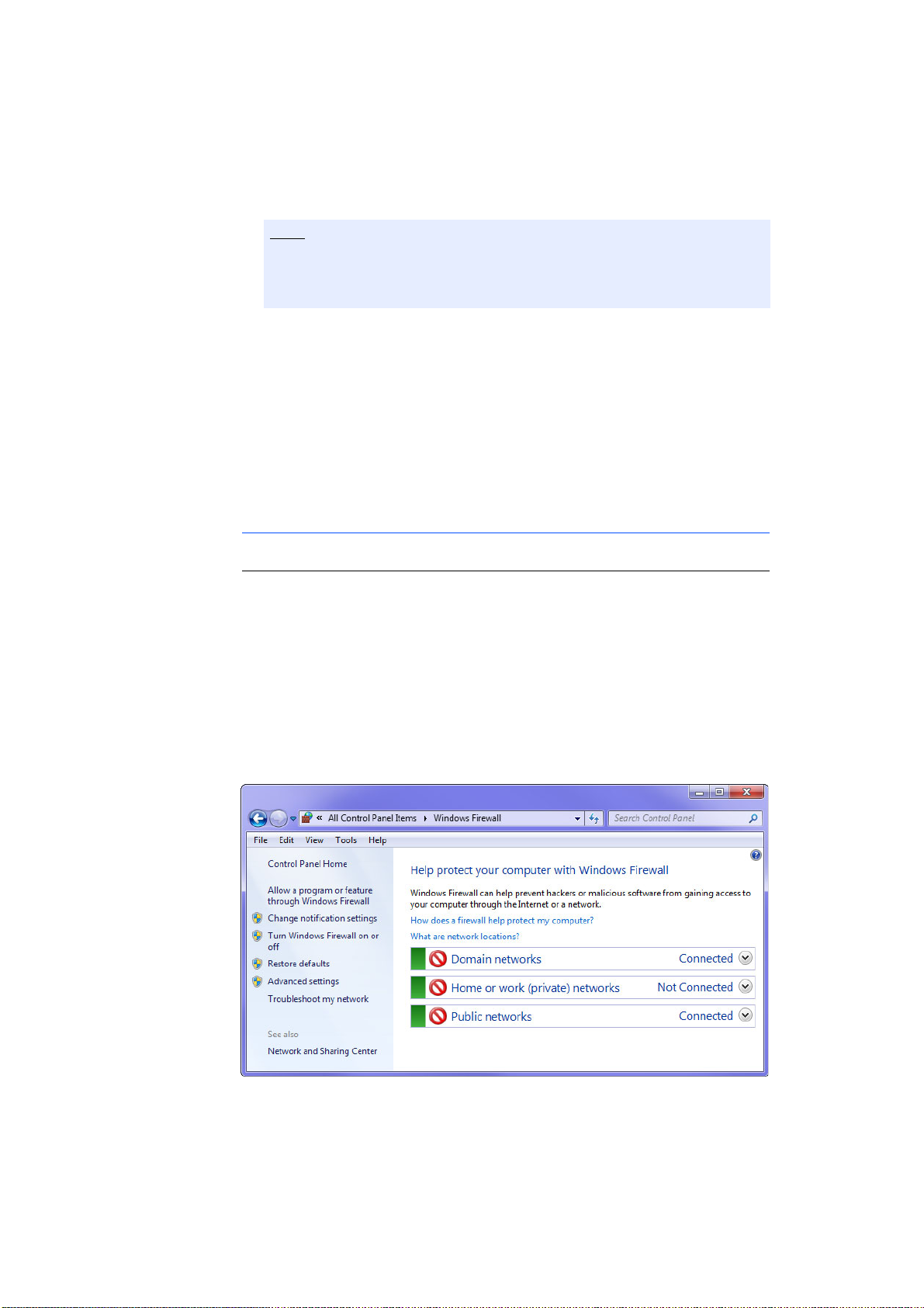
ETAS
Note
• Outgoing TCP/IP connections to the network configured for the ETAS
application, destination ports 18001 to 18020
The ports to be used in a specific case depend on the hardware used. For
more detailed information about the port numbers to be used, see the
respective hardware documentation.
In Windows 7, 8.1 and 10, a Personal Firewall program is part of the scope of
delivery and enabled by default. On many other systems, similar programs from
independent providers can frequently be found, such as Symantec, McAfee or
BlackIce. The procedure for the configuration of ports may differ in the various
programs. More detailed information can be found in the user documentation of
your firewall program.
Below is a sample description about how to configure the Windows firewall if
the hardware access is being blocked.
Solution for Windows Firewall, user with administrator rights
Enabling ETAS products in the firewall control:
1. Open the Control Panel:
– Windows 7, 10:
1.1 Click on the Windows symbol.
1.2 Click on Control Panel.
– Windows 8.1:
1.1 Click on the Windows symbol.
1.2 Enter Control Panel in the entry field.
1.3 Push <E
NTER>.
2. Click on Windows Firewall (Win 7, 8.1) or Win-
dows Defender Firewall (Win 10).
ES415.1 - User’s Guide68
Page 69
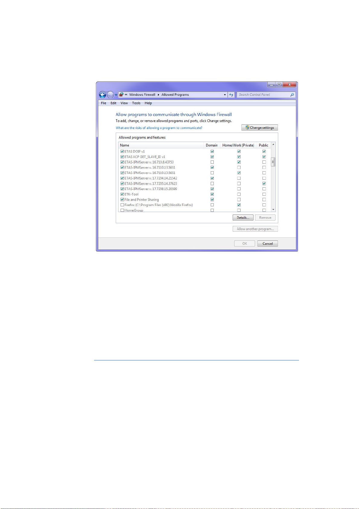
ETAS
3. Click on Allow a program / app or feature
through Windows (Defender) Firewall.
This window lists the exceptions that are not
blocked by the firewall.
4. Click on Change settings.
5. Check the boxes to enable the respective program
for the corresponding network.
6. Ensure that the ETAS products and services to be
used are correctly configured exceptions.
7. Klick on OK.
8. Close the Windows Firewall.
The firewall no longer blocks the ETAS product. The
setting is retained after a restart of the PC.
Solution for Windows Firewall, user without administrator rights
This chapter is directed at users with restricted rights, e.g. no changes to the
system, restricted write permissions, local login.
Working with an ETAS product requires the rights "Write" and "Modify" in the
directories ETAS, ETASData and the temporary ETAS directories. Otherwise, an
error message appears if the product is being started and a database is being
opened. A correct operation of the product is not possible since the database file
as well as various *.ini files are modified during the work.
The ETAS software must be installed by an administrator in any case. It is recommended that the administrator ensures that the ETAS product or the processes
are added to the list of selected exceptions of the Windows Firewall after the
installation.
ES415.1 - User’s Guide 69
Page 70
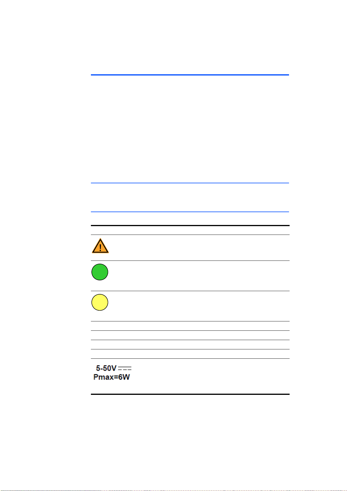
Technical Data ETAS
7 Technical Data
This chapter contains information on the following topics:
• "General Data" on page 70
• "RoHS conformity" on page 74
• "CE marking" on page 74
• "Product return and recycling" on page 74
• "Declarable Substances" on page 75
• "Use of Open Source software" on page 75
• "System Requirements" on page 75
• "Electrical Data" on page 77
• "Pin Assignment" on page 82
7.1 General Data
This section contains details of the admissible environmental conditions as well
as the mechanical data.
7.1.1 Product labeling
The following symbols are used for product labeling:
Symbol Description
CH Connection of sensor cable
SN: 1234567 Serial number (seven-digit)
Vx.y.z Hardware version of the product
F 00K 123 456 Ordering number of the product, see chapter 9.1 on page 104
Prior to operating the product, be sure to read the user’s
guide!
Labeling of the daisy chain port„IN“ (input; Ethernet connection to the upstream module or the PC, power supply of the
module)
Labeling of the daisy chain port„OUT“ (output; Ethernet connection and power supply of the downstream module)
Operating voltage range (DC), Power consumption
ES415.1 - User’s Guide70
Page 71
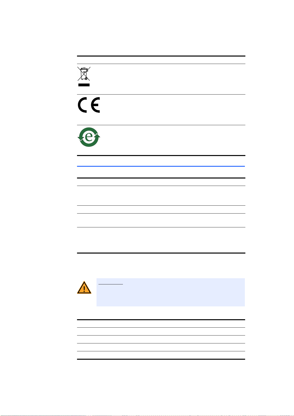
ETAS Technical Data
WARNING!
Symbol Description
Labeling for WEEE, see chapter 7.4 on page 74
Labeling for CE conformity, see chapter 7.3 on page 74
Labeling for RoHS (China), see chapter 7.2.2 on page 74
7.1.2 Standards and Norms
The module adheres to the following standards and norms:
Standard Test
EN 61326 Electrical equipment for measurement,
control and laboratory use - EMC
requirements
EN 61000-6-2 Immunity (industrial environments)
1)
EN 61000-6-4 Emission standard (industrial environ-
ments)
1)
: The module must be supplied by a DC power supply or a battery with operating voltage. Between module and voltage source, cables with a maximum
length of 30 m are allowed.
The module is designed only for use in industrial environments in accordance
with EN 61000-6-4. When using the module outside of industrial environments
avoid possible radio disturbances by additional shielding measures!
This is a class A product. In a domestic environment this product may
cause radio interference in which case the user may be required to
take adequate measures.
Norm Test
DIN EN 60068-2-1 Premature fatigue cold test
DIN EN 60068-2-2 Premature fatigue heat test
DIN EN 60068-2-13 Negative pressure
DIN EN 60068-2-14 Na Temperature shock
ES415.1 - User’s Guide 71
Page 72

Technical Data ETAS
Norm Test
DIN EN 60068-2-14 Nb Temperature change:
Temperature: Tu –40 °C / To +120 °C,
Number of cycles: 10,
Unit under test: active
DIN EN 60068-2-56 Humidity storage
DIN EN 60068-30, Variant 1 Climate change
DIN EN 60068-2-64,
ISO 16750-3
ISO 16750-3, Sec. 4.2.2.2 Mech. shock
ISO 16750-3, Sec. 4.3 Drop test
ISO 16750-4, Sec. 5.2 Phased temperature test
ISO 16750-4, Sec. 5.4.2 Splash water
ISO 16750-4, Sec. 5.5.1.;
DIN EN 60068-2-52
ISO 16750-5 Chemical resistance:
DIN 5596-1 Stone impact
IPX7 Protection class test:
Vibration, noise:
3 space axis, test duration 4 h,
Unit under test: active
In addition, the combination was tested
by cascaded modules.
3 space axis, half sinus,
Acceleration: 500 m/s²,
Shock duration: 6 ms,
Shocks per direction and axis: 10,
Units under test: active
Number of drops: 2,
Height: 1 m,
Surface: concrete, steel
Units under test: passive
Air temperature: To +120 °C,
Cycle duration: 30 min,
Splash length: 3 s,
Splash quantity: ca. 3 l,
Splash water temperatur: +2 °C ± 2 °C,
Medium: water, put in 3% Arizona dust
fine,
Number of cycles: 100,
Unit under test: active
Salt fog:
Severity level: 5,
Test duration: 16 d,
Units under test: passive
Identification A-W,
Prüflinge passiv
Protection class IP67
ES415.1 - User’s Guide72
Page 73
ETAS Technical Data
CAUTION!
7.1.3 Environmental Conditions
Operating temperature range -40 °C to +120 °C
-40 °F to +248 °F
Storage temperature range
(module without packaging)
Implementation altitude max. 5000 m / 16400 ft
Protection class IP67
Loss of Features as defined by IP67!
Do not open or change the module housing!
Works on the module housing may be executed only by qualified
technical personnel.
7.1.4 Maintenance the Product
-40 °C to +125 °C
-40 °F to +257 °F
Do not open or change the module! Works on the module housing may be executed only by qualified technical personnel. Send defect modules to ETAS.
7.1.5 Cleaning the product
We recommend to clean the product with a dry cloth.
7.1.6 Mechanical Data
Dimensions (H x W x D) 51.5 mm x 40 mm x 139 mm /
Weight 350 g / 0.77 lb
7.1.7 Modules in one chain
Modules in chain Max. 254 in one chain
37.5 mm x 40 mm x 124 mm
2.0 in x 1.57 in x 5.47 in
1.48 in x 1.57 in x 4.88 in
ES415.1 - User’s Guide 73
Page 74

Technical Data ETAS
7.2 RoHS conformity
7.2.1 European Union
The EU Directive 2011/65/EU limits the use of certain dangerous materials for
electric and electronic devices (RoHS conformity).
ETAS confirms that the product meets this directive applicable in the European
Union.
7.2.2 China
ETAS confirms that the product meets the "China RoHS" (Management Methods
for Controlling Pollution Caused by Electronic Information Products Regulation)
guidelines applicable to the People's Republic of China with a China RoHS label
attached to the product or its packaging.
7.3 CE marking
With the CE mark attached to the product or its packaging, ETAS confirms that
the product corresponds to the product-specific, applicable European Directives.
The CE Declaration of Conformity for the product is available upon request.
7.4 Product return and recycling
The European Union (EU) has issued the guideline on waste electric and electronic equipment (Waste Electrical and Electronic Equipment - WEEE) in order to
ensure the institution of systems for collection, handling, and disposal of all electronic scrap.
This ensures that the devices are recycled in a resource-friendly way that does not
represent any risk to personal health and the environment.
Fig. 7-1 WEEE symbol
The WEEE symbol (see Fig. 7-1 on page 74) on the product or its packaging identifies that the product may not be disposed of together with the remaining trash.
The user is obligated to separate the waste equipment and to provide it to the
WEEE return system for reuse.
The WEEE Directive applies to all ETAS devices, but not to external cables or batteries.
Additional information about the recycling program of ETAS GmbH is available
from the ETAS sales and service locations (see chapter 10 on page 108).
ES415.1 - User’s Guide74
Page 75

ETAS Technical Data
Note
7.5 Declarable Substances
European Union
Some products from ETAS GmbH (e.g. modules, boards, cables) use components
with substances that are subject to declaration in accordance with the REACH
regulation (EU) no.1907/2006.
Detailed information is located in the ETAS download center in the customer
information "REACH Declaration" (www.etas.com/Reach
continuously being updated.
). This information is
7.6 Use of Open Source software
The product uses Open Source Software (OSS). This software is installed in the
product at the time of delivery and does not have to be installed or updated by
the user. Reference shall be made to the use of the software in order to fulfill OSS
licensing terms. Additional information is available in the document "OSS Attributions List" at the ETAS website www.etas.com.
7.7 System Requirements
This section tells you what hardware and software is needed to operate your
ES415.1 module.
7.7.1 Hardware
Power supply
Operation of the modules requires a power supply voltage of 5 V to 50 V/ 6 V to
50 V DC.
PC with one Ethernet interface
A PC with one open Ethernet interface (100 Mbit/s, full duplex) with RJ-45 connection is required.
Requirement to ensure successful initialization of the module
It is imperative you disable the function which automatically switches to powersaving mode on your PC network adapter when there is no data traffic on the
Ethernet interface!
To deactivate the power saving mode:
Choose in System Control Center / Device Manager / Network Adapter the used
network adapter by double-click. Deactivate the "Allow the computer to turn off
this device to save power" option in the "Power Management" register. Confirm
your configuration.
The manufacturers of network adapter have different names for this function.
Example:
• “Link down Power saving”
• "Allow the computer to turn off this device to save power".
ES415.1 - User’s Guide 75
Page 76

Technical Data ETAS
Note
7.7.2 Software
To configure the ES415.1 and for control and data acquisition, you need software in the following versions:
General
• ES4xx Configuration Tool V1.3.4 and higher from ES4xx_DRV_SW (standalone operation)
• HSP V9.9.3 and higher
Measurement and Calibration (MC)
• INCA V7.0 and higher with INCA Add-On ES4xx V1.3.4 and higher
Rapid Prototyping (RP)
• INTECRIO V4.2 and higher
or
• INTECRIO-RLINK V1.0 and higher
or
• ASCET-RP V6.1.3 and higher
Operating the ES415.1 with older versions of software is not possible.
ES415.1 - User’s Guide76
Page 77

ETAS Technical Data
Note
Note
Note
7.8 Electrical Data
This chapter contains information on the following topics:
• "Host Interface ("IN" Connection)" on page 77
• "Power Supply" on page 78
• "Sensor Power Supply" on page 78
• "Sensor Inputs" on page 79
• "Signal Processing" on page 81
ETAS guarantees measurement accuracy of the ES415.1 for one year. Please
use our calibration service (see section 4.9 on page 33)!
Unless otherwise specified, all data applies at 25 °C.
7.8.1 Host Interface ("IN" Connection)
Connection 100Base-T Ethernet; 100 Mbit/s,
Full Duplex
Protocol XCP on UDP/IP
IP address Dynamic via INCA or via
ES4xx Configuration Tool
(default setting: 192.168.40.44)
For the successful initialization of the network card of your PC, observe chapter
7.7.1 on page 75.
ES415.1 - User’s Guide 77
Page 78

Technical Data ETAS
7.8.2 Power Supply
Operating voltage
(dry environment)
Operating voltage
(wet environment)
Power consumption (operation, sensors not connected)
Power consumption (operation; all
channels loaded with 30 mA)
Power consumption (standby, sensors
not connected, room temperature)
Polarity inversion protection, load
dump protection
1)
: The module may be used only with central load dump protection.
1)
7.8.3 Sensor Power Supply
Temperature range -40 °C to +85 °C:
5V to 50V DC
Temperature range -40 °C to +120 °C:
6V to 50V DC
Temperature range -40 °C to +85 °C:
5V to 32V DC
Temperature range -40 °C to +120 °C:
6V to 32V DC
Typ. 2.2 W at 12 V DC
Max. 6 W at 12 V DC
Typ. 25 mW at 12 V DC
With CBEP410, CBEP4105, CBEP415,
CBEP4155, CBEP420, CBEP4205,
CBEP425, CBEP4255, CBEP430,
CBEP4305 cable
Features
Sensor power supply channels 4, separate per input channel
Output voltage Each channel can be set separately:
“Off”, in steps (5 V, 8 V, 10 V, 12 V) or
freely selectable as a value in the range
5V to 15V
D/A converter 16-bit (resolution 229 V)
Protection Outputs (plus) short-circuit proof against
ground and up to 26 V overvoltage.
Ground connected to operating voltage
ground and protected by a fuse.
Diagnostics Short-circuit detection per channel; over-
load conditions reduce the output voltage
ES415.1 - User’s Guide78
Page 79

ETAS Technical Data
Characteristics
Parameter Min Max Unit
Accuracy of the sensor supply voltage with-
-±10mV
out load
Accuracy of the sensor supply voltage with
-±5mV
3k load
Resistance of analog outputs including
-1.6Ohm
CBAV411.1-2 cable
Ripple voltage V
(measurement limited to
pp
-20mV
80 MHz)
Max. voltage drift (temperature) -1 +1.2 mV/K
Output current - 30 mA
7.8.4 Sensor Inputs
Features
Input channels 4, with separate sensor power supply
A/D converter One A/D converter per channel, 16-bit
resolution
Hardware input filter Low-pass 4th order, Butterworth,
cutoff frequency 50 kHz
Input voltage ranges -100 mV to +100 mV
-1 V to +1 V
-10 V to +10 V
-60 V to +60 V
Maximum input voltage Input-to-input:
60 V DC / 30 V AC
Input-to-ground of voltage supply or
housing:
60 V DC / 30 V AC
ES415.1 - User’s Guide 79
Page 80

Technical Data ETAS
Characteristics
Maximum input voltage resolution
(16-bit)
±100 mV measurement range:
3.6 V
±1 V measurement range:
37.2 V
±10 V measurement range:
366 V
±60 V measurement range:
2.16 mV
Maximum measurement error ±100 mV measurement range:
±(100 V + |U
| * 0.1%)
IN
±1 V measurement range:
±(500 V + |U
| * 0.05%)
IN
±10 V measurement range:
±(3 mV + |U
| * 0.05%)
IN
±60 V measurement range:
Max. voltage drift (temperature),
temperature range -40 °C to +85 °C
±(16 mV + |U
±100 mV measurement range:
8 V/K
| * 0.2%)
IN
±1 V measurement range:
8 V/K
±10 V measurement range:
36 V/K
±60 V measurement range:
3.6 mV/K
Max. voltage drift (temperature),
temperature range +85 °C to
+120 °C
±100 mV measurement range:
150 V/K
±1 V measurement range:
150 V/K
±10 V measurement range:
360 V/K
±60 V measurement range:
3.6 mV/K
Input impedance Measurement ranges ±0.1 V, ±1V:
> 10 M || < 300 pF
Measurement ranges ±10 V, ±60 V:
> 2 M || < 400 pF
Module not powered:
> 2 M || < 400 pF
ES415.1 - User’s Guide80
Page 81

ETAS Technical Data
Note
7.8.5 Signal Processing
Resolution 16 Bit, increased with slow sampling
rates
Sampling rate Measurement and Calibration (MC):
0.5 to 100000 samples/s (100 kHz), can
be configured individually for each channel
Rapid Prototyping (RP):
0.5 to 10000 samples/s (10 kHz), can be
configured individually for each channel
Hardware input filter Low-pass 4th order, Butterwoth,
Cutoff frequency 50 kHz
Digital low-pass filter CIC filter (sinc filter), automatic filter set-
ting with selection of scanning rate, can
be disabled
Averaging time
= 10 s to 2 s,
s
Averaging time equal to scanning rate
To avoid an IRQ overload at the I/O port of the ES910.3 Prototyping Module or
ETAS RTPRO-PC, the sample rate of the ES415.1 module is automatically limited to 10 kHz for Rapid Prototyping applications (see chapter 4.3.3
on page 21).
ES415.1 - User’s Guide 81
Page 82
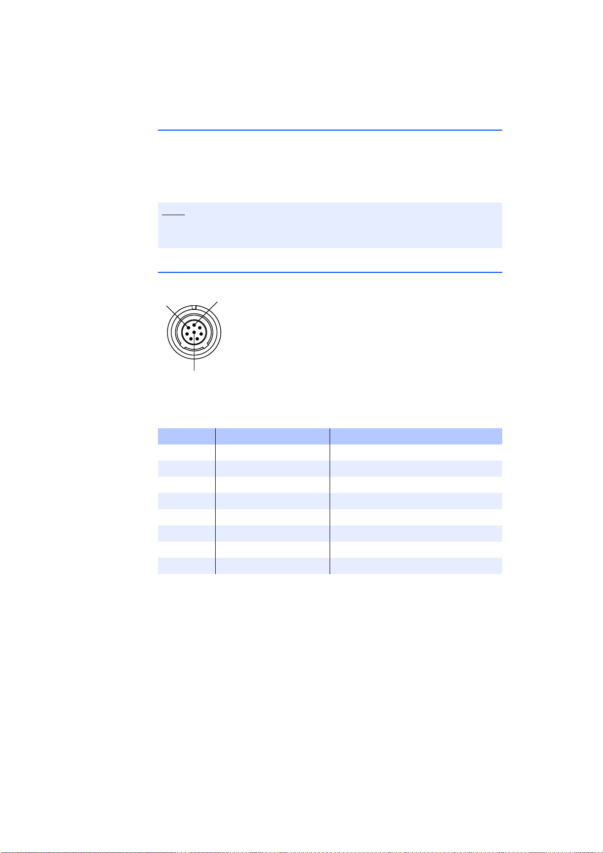
7.9 Pin Assignment
Note
N
T
U
This chapter contains information on the following topics:
• "“IN” Connector" on page 82
• "“OUT” Connector" on page 83
• "“Sensor” Connector" on page 84
All connectors are shown with a view of the front of the ES415.1.
All shields are at case potential.
7.9.1 “IN” Connector
ETAS
Fig. 7-2 “IN” Connector
Pin Signal Meaning
1 UBatt Operating voltage
2 Ground Ground
3 RX- Received data, minus
4 TX- Send data, minus
5 RX+ Received data, plus
6 Ground Ground
7 UBatt Operating voltage
8 TX+ Send data, plus
The following plug is mounted on "IN" connector:
LEMO 1B 8-pin L-coding (connection identified in green)
ES415.1 - User’s Guide82
Page 83
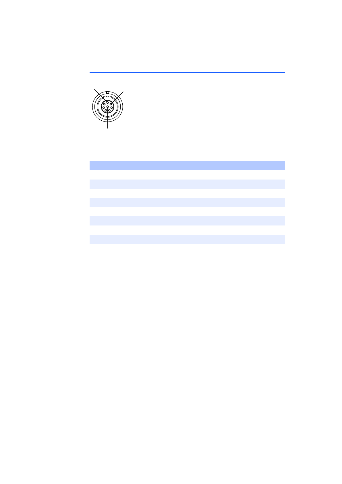
ETAS
N
T
U
7.9.2 “OUT” Connector
Fig. 7-3 “OUT” Connector
Pin Signal Meaning
1 UBatt Operating voltage
2 UBatt Operating voltage
3 Ground Ground
4 RX+ Received data, plus
5 TX- Send data, minus
6 RX- Received data, minus
7 Ground Ground
8 TX+ Send data, plus
The following socket is mounted on "OUT" connector:
LEMO 1B 8-pin A-coding (connection identified in yellow)
ES415.1 - User’s Guide 83
Page 84

7.9.3 “Sensor” Connector
Fig. 7-4 “Sensor” Connector
Pin Signal Meaning
1 CH2 In+ Sensor channel 2, input plus
2 CH2 SGND Sensor channel 2, Sensor supply voltage, GND
3 CH2 S+ Sensor channel 2, Sensor supply voltage, plus
4 CH3 SGND Sensor channel 3, Sensor supply voltage, GND
5 CH3 S+ Sensor channel 3, Sensor supply voltage, plus
6 CH3 In- Sensor channel 3, input minus
7 CH3 In+ Sensor channel 3, input plus
8 CH4 In+ Sensor channel 4, input plus
9 CH4 In- Sensor channel 4, input minus
10 CH4 S+ Sensor channel 4, Sensor supply voltage, plus
11 CH4 SGND Sensor channel 4, Sensor supply voltage, GND
12 CH1 S+ Sensor channel 1, Sensor supply voltage, plus
13 CH1 SGND Sensor channel 1, Sensor supply voltage, GND
14 CH1 In+ Sensor channel 1, input plus
15 CH2 In- Sensor channel 2, input minus
16 CH2 TEDS+ Sensor channel 2, TEDS+
17 CH3 TEDS+ Sensor channel 3, TEDS+
18 TEDS+ Cable, TEDS+
19 CH4 TEDS+ Sensor channel 4, TEDS+
20 CH1 TEDS+ Sensor channel 1, TEDS+
21 CH1 In- Sensor channel 1, input -
22 CH1 TEDS-
CH2 TEDSCH3 TEDSCH4 TEDSTEDS-
ETAS
*)
*)
*)
*)
Sensor channel 1, TEDSSensor channel 2, TEDSSensor channel 3, TEDSSensor channel 4, TEDSCable, TEDS-
*): connected with operating voltage ground
ES415.1 - User’s Guide84
Page 85

ETAS Cables and Accessories
Note
8 Cables and Accessories
This chapter contains information on the following topics:
• "Combined Ethernet and Power Supply Cable" on page 86
• "Ethernet Cable" on page 92
• "Cable for the Connection "Sensor"" on page 95
• "Measurement Probes and Cables" on page 98
• "Protective Caps" on page 102
• "Angle Brackets" on page 103
Only use ETAS cables at the interfaces of the module. Adhere to the maximum
cable lengths!
ES415.1 - User’s Guide 85
Page 86
8.1 Combined Ethernet and Power Supply Cable
DANGER!
This chapter contains information on the following cables:
• "CBEP410.1 Cable" on page 87
• "CBEP4105.1 Cable" on page 87
• "CBEP415.1 Cable" on page 88
• "CBEP4155.1 Cable" on page 88
• "CBEP420.1 Cable" on page 89
• "CBEP4205.1 Cable" on page 89
• "CBEP425.1 Cable" on page 90
• "CBEP4255.1 Cable" on page 90
• "CBEP430.1 Cable" on page 91
• "CBEP4305.1 Cable" on page 91
8.1.1 Overview
ETAS
Dangerous electrical voltage!
Connect the power cable only with a suitable vehicle battery or with
a suitable lab power supply! The connection to power outlets is not
allowed!
To prevent an inadvertent insertion in power outlets, ETAS recommends to equip the combined ethernet and power supply cables with
safety banana plugs in areas with power outlets.
You can use combined ethernet and power supply cables with standard banana
plugs or with safety banana plugs:
Cables with standard banana plugs Cables with safety banana plugs
CBEP410.1 CBEP4105.1
CBEP415.1 CBEP4155.1
CBEP420.1 CBEP4205.1
CBEP425.1 CBEP4255.1
CBEP430.1 CBEP4305.1
ES415.1 - User’s Guide86
Page 87
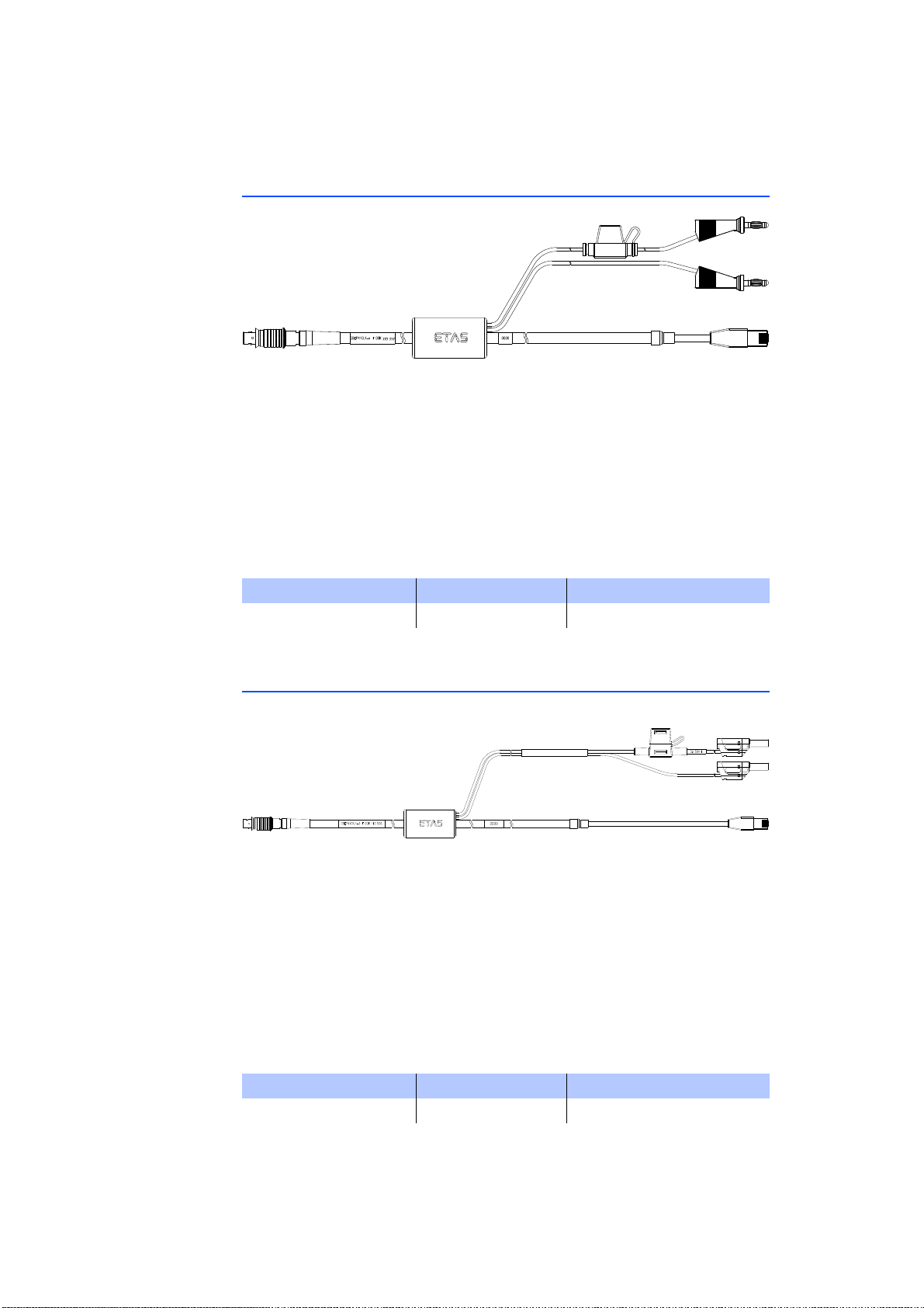
ETAS
8.1.2 CBEP410.1 Cable
Fig. 8-1 CBEP410.1 Cable
Connection of an ES4xx/ES63x/ES93x module to PC and power supply (standalone operation). Supply battery in the vicinity of the module.
Not compatible with ES610, ES611, ES620 and ES650. For connecting this modules use CBEP120 cable.
Cable includes reverse-polarity, load-dump protection and replaceable standard
fuse (MINI flat automotive fuse, quick-response, 3 A, 58 V).
Robust, waterproof and dust-proof (IP67).
Temperature rated for: -40 °C to +125 °C / -40 °F to +257 °F
Product Length Order number
CBEP410.1-3 3 m F 00K 104 927
8.1.3 CBEP4105.1 Cable
Fig. 8-2 CBEP4105.1 Cable
Connection of an ES4xx/ES63x/ES93x module to PC and power supply (standalone operation). Supply battery in the vicinity of the module.
Not compatible with ES610, ES611, ES620 and ES650. For connecting this modules use CBEP120 cable.
Cable includes reverse-polarity, load-dump protection and replaceable standard
fuse (MINI flat automotive fuse, quick-response, 3 A, 58 V).
Robust, waterproof and dust-proof (IP67).
Temperature rated for: -40 °C to +125 °C / -40 °F to +257 °F
Product Length Order number
CBEP4105.1-3 3 m F 00K 110 026
ES415.1 - User’s Guide 87
Page 88
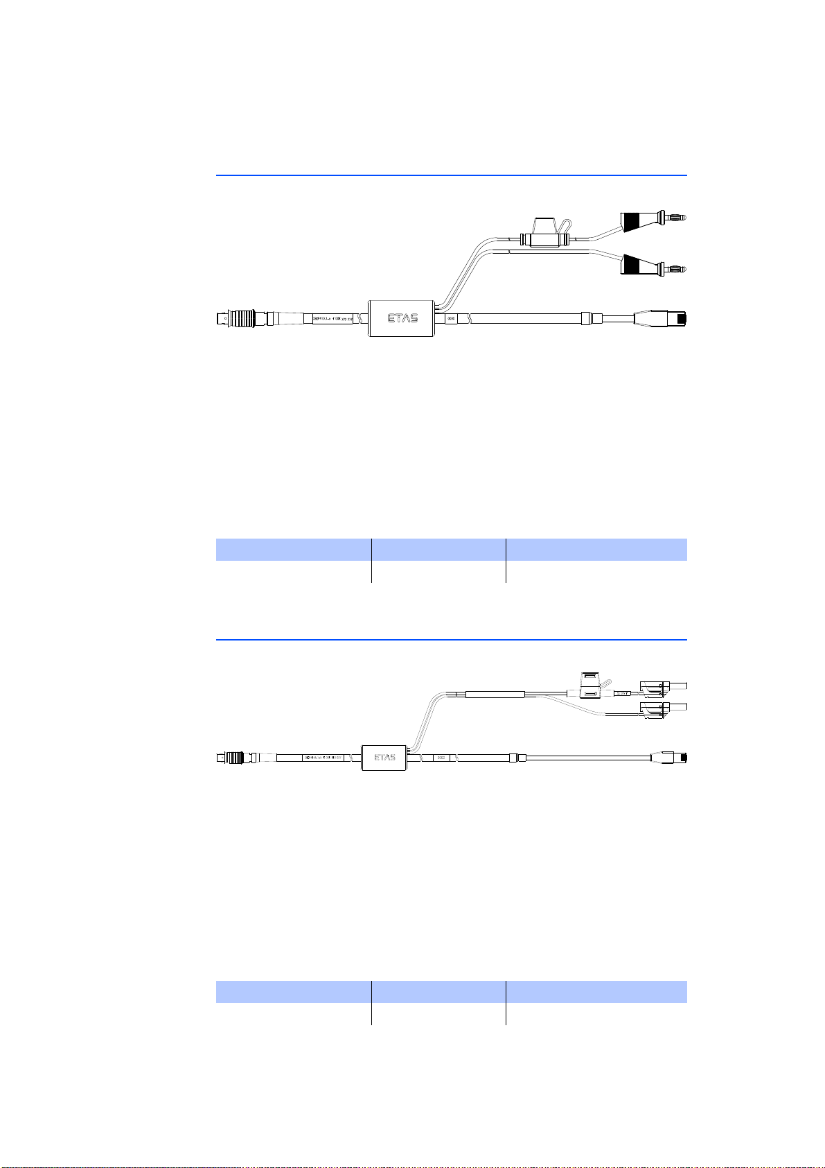
8.1.4 CBEP415.1 Cable
Fig. 8-3 CBEP415.1 Cable
Connection of an ES4xx/ES63x/ES93x module to PC and power supply (standalone operation). Supply battery at the other end (i.e. in the trunk).
Not compatible with ES610, ES611, ES620 and ES650. For connecting this modules use CBEP120 cable.
Cable includes reverse-polarity, load-dump protection and replaceable standard
fuse (MINI flat automotive fuse, quick-response, 3 A, 58 V).
Robust, waterproof and dust-proof (IP67).
Temperature rated for: -40 °C to +125 °C / -40 °F to +257 °F
ETAS
Product Length Order number
CBEP415.1-5 5 m F 00K 105 680
8.1.5 CBEP4155.1 Cable
Fig. 8-4 CBEP4155.1 Cable
Connection of an ES4xx/ES63x/ES93x module to PC and power supply (standalone operation). Supply battery at the other end (i.e. in the trunk).
Not compatible with ES610, ES611, ES620 and ES650. For connecting this modules use CBEP120 cable.
Cable includes reverse-polarity, load-dump protection and replaceable standard
fuse (MINI flat automotive fuse, quick-response, 3 A, 58 V).
Robust, waterproof and dust-proof (IP67).
Temperature rated for: -40 °C to +125 °C / -40 °F to +257 °F
Product Length Order number
CBEP4155.1-5 5 m F 00K 110 027
ES415.1 - User’s Guide88
Page 89
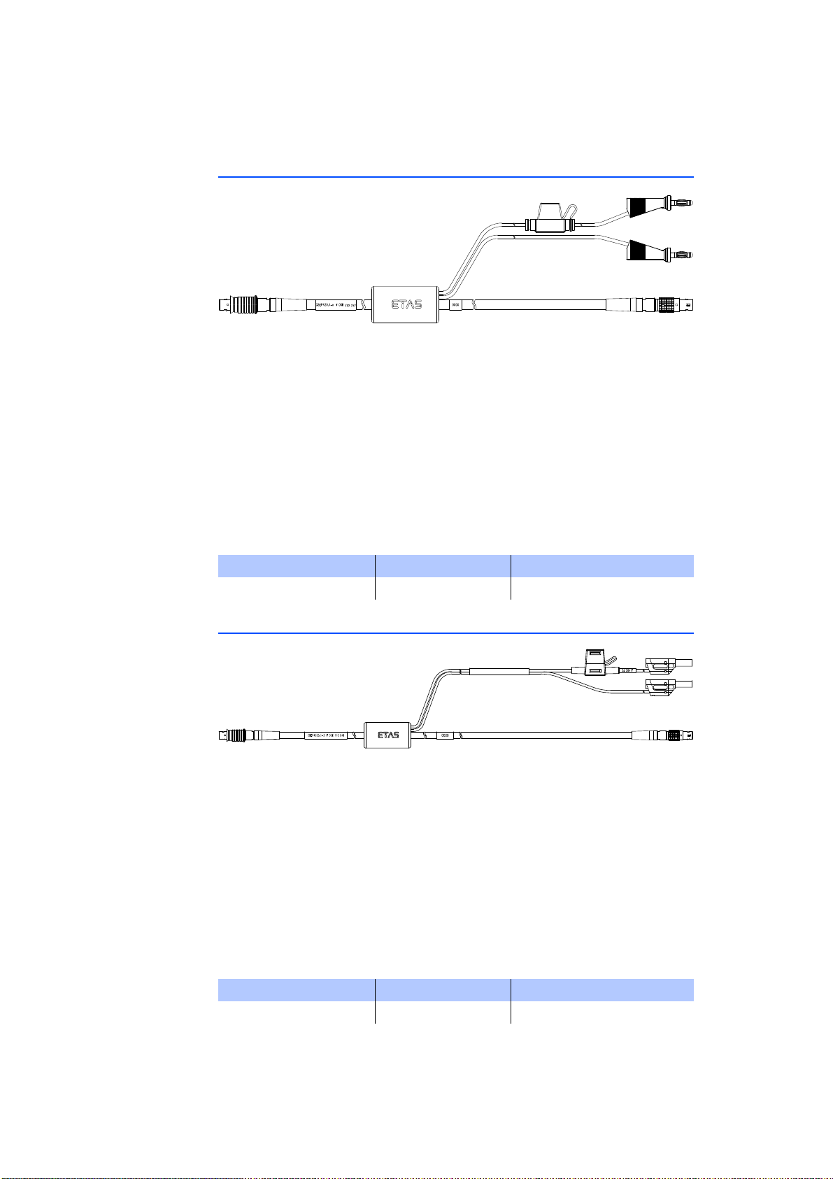
ETAS
8.1.6 CBEP420.1 Cable
Fig. 8-5 CBEP420.1 Cable
Ethernet and voltage supply connection of an ES4xx/ES63x/ES93x measurement
module with an ES600 network module or ES592/ES593-D/ES595 interface
module (if the current consumption of the connected ES4xx/ES63x chain exceeds
2.5 A), an ES1135 simulation/system controller card or an ES720 Drive Recorder.
Not compatible with ES610, ES611, ES620 and ES650. For connecting this modules use CBEP120 cable.
Cable includes reverse-polarity, load-dump protection and replaceable standard
fuse (MINI flat automotive fuse, quick-response, 3 A, 58 V).
Robust, waterproof and dust-proof (IP67).
Temperature rated for: -40 °C to +125 °C / -40 °F to +257 °F
Product Length Order number
CBEP420.1-3 3 m F 00K 105 292
8.1.7 CBEP4205.1 Cable
Fig. 8-6 CBEP4205.1 Cable
Ethernet and voltage supply connection of an ES4xx/ES63x/ES93x measurement
module with an ES600 network module or ES592/ES593-D/ES595 interface
module (if the current consumption of the connected ES4xx/ES63x chain exceeds
2.5 A), an ES1135 simulation/system controller card or an ES720 Drive Recorder.
Not compatible with ES610, ES611, ES620 and ES650. For connecting this modules use CBEP120 cable.
Cable includes reverse-polarity, load-dump protection and replaceable standard
fuse (MINI flat automotive fuse, quick-response, 3 A, 58 V).
Robust, waterproof and dust-proof (IP67).
Temperature rated for: -40 °C to +125 °C/ -40 °F to +257 °F
Product Length Order number
CBEP4205.1-3 3 m F 00K 110 041
ES415.1 - User’s Guide 89
Page 90
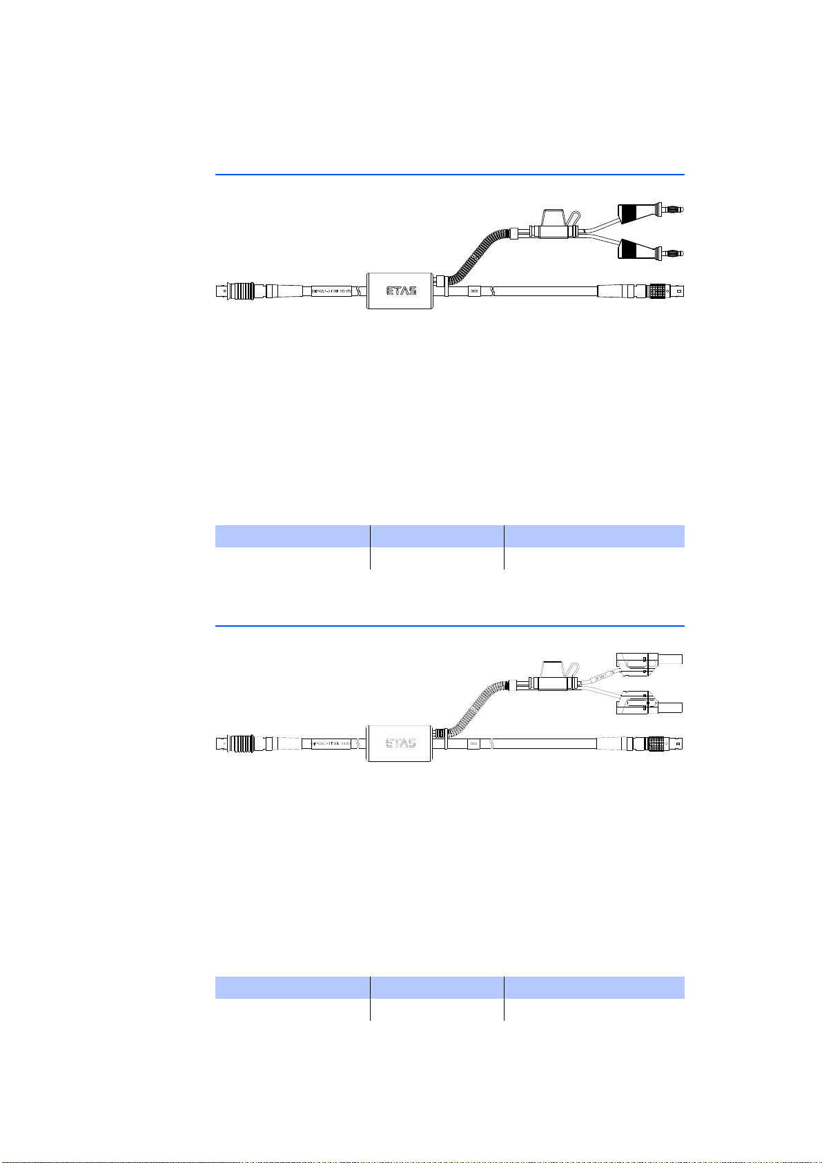
8.1.8 CBEP425.1 Cable
Fig. 8-7 CBEP425.1 Cable
Ethernet and voltage supply connection of an ES4xx/ES63x/ES93x measurement
module with an ES600 network module or ES592/ES593-D/ES595 interface
module (if the current consumption of the connected ES4xx/ES63x/ES93x chain
exceeds 2.5 A), an ES1135 simulation/system controller card or an ES720 Drive
Recorder.
Cable includes reverse-polarity, load-dump protection and replaceable standard
fuse (MINI flat automotive fuse, quick-response, 3 A, 58 V).
Robust, waterproof and dust-proof (IP67).
Temperature rated for: -40 °C to +125 °C / -40 °F to +257 °F
ETAS
Product Length Order number
CBEP425.1-3 3 m F 00K 105 972
8.1.9 CBEP4255.1 Cable
Fig. 8-8 CBEP4255.1 Cable
Ethernet and voltage supply connection of an ES4xx/ES63x/ES93x measurement
module with an ES600 network module or ES592/ES593-D/ES595 interface
module (if the current consumption of the connected ES4xx/ES63x/ES93x chain
exceeds 2.5 A), an ES1135 simulation/system controller card or an ES720 Drive
Recorder.
Cable includes reverse-polarity, load-dump protection and replaceable standard
fuse (MINI flat automotive fuse, quick-response, 3 A, 58 V).
Robust, waterproof and dust-proof (IP67).
Temperature rated for: -40 °C to +125 °C / -40 °F to +257 °F
Product Length Order number
CBEP4255.1-3 3 m F 00K 110 029
ES415.1 - User’s Guide90
Page 91
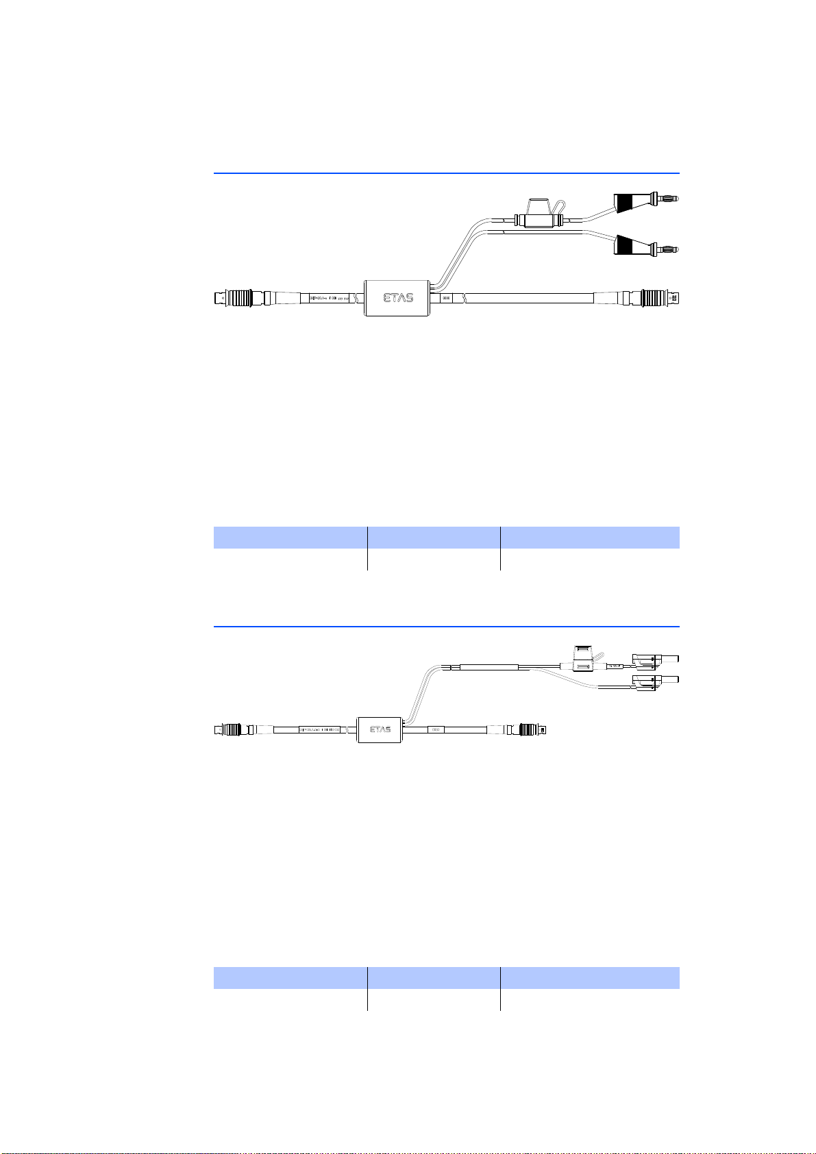
ETAS
8.1.10 CBEP430.1 Cable
Fig. 8-9 CBEP430.1 Cable
To chain ES4xx/ES63x/ES93x modules and connect an ES4xx/ES63x/ES93x chain
to an ES910.3 Rapid Prototyping module. Additional connection to the power
supply to compensate for voltage losses in long chains.
Not compatible with ES59x, ES6xx, ES11xx. For connecting this modules use
CBE130 or CBE140 cable.
Cable includes reverse-polarity, load-dump protection and replaceable standard
fuse (MINI flat automotive fuse, quick-response, 3 A, 58 V).
Robust, waterproof and dust-proof (IP67).
Temperature rated for: -40 °C to +125 °C / -40 °F to +257 °F
Product Length Order number
CBEP430.1-0m5 0.5 m F 00K 104 928
8.1.11 CBEP4305.1 Cable
Fig. 8-10 CBEP4305.1 Cable
To chain ES4xx/ES63x/ES93x modules and connect an ES4xx/ES63x/ES93x chain
to an ES910.3 Rapid Prototyping module. Additional connection to the power
supply to compensate for voltage losses in long chains.
Not compatible with ES59x, ES6xx, ES11xx. For connecting this modules use
CBE130 or CBE140 cable.
Cable includes reverse-polarity, load-dump protection and replaceable standard
fuse (MINI flat automotive fuse, quick-response, 3 A, 58 V).
Robust, waterproof and dust-proof (IP67).
Temperature rated for: -40 °C to +125 °C / -40 °F to +257 °F
Product Length Order number
CBEP4305.1-0m5 0.5 m F 00K 110 030
ES415.1 - User’s Guide 91
Page 92
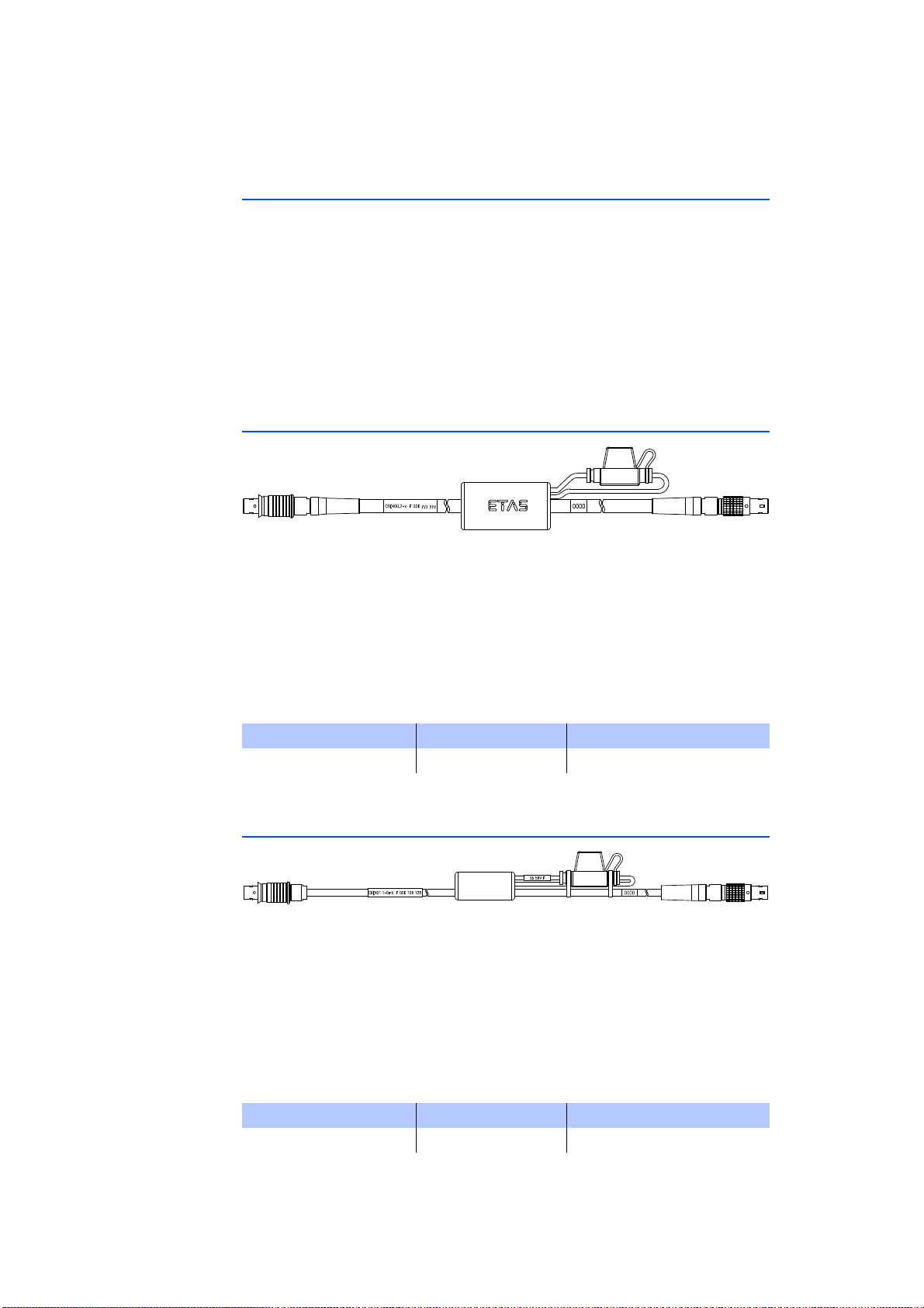
8.2 Ethernet Cable
This chapter contains information on the following cables:
• "CBE400.2 Cable" on page 92
• "CBE401.1 Cable" on page 92
• "CBE430.1 Cable" on page 93
• "CBE431.1 Cable" on page 93
• "CBEX400.1 Cable" on page 94
• "ES4xx_BRIDGE" on page 94
8.2.1 CBE400.2 Cable
ETAS
Fig. 8-11 CBE400.2 Cable
Ethernet and voltage supply connection of an ES4xx/ES63x/ES93x measuring
module at an ES600 network module or at an ES592/ES593-D/ES595 interface
module.
Cable includes reverse-polarity, load-dump protection and replaceable standard
fuse (MINI flat automotive fuse, quick-response, 3 A, 58 V).
Robust, waterproof and dust-proof (IP67).
Temperature rated for: -40 °C to +125 °C / -40 °F to +257 °F
Product Length Order number
CBE400.2-3 3 m F 00K 104 920
8.2.2 CBE401.1 Cable
Fig. 8-12 CBE401.1 Cable
Highly flexible Ethernet and voltage supply connection of an ES4xx/ES63x/ES93x
measuring module at an ES600 network module or at an ES592/ES593-D/ES595
interface module.
Cable includes reverse-polarity, load-dump protection and replaceable standard
fuse (MINI flat automotive fuse, quick-response, 3 A, 58 V).
Robust, waterproof and dust-proof (IP67).
Temperature rated for: -40 °C to +125 °C / -40 °F to +257 °F
Product Length Order number
CBE401.1-0m5 0.5 m F 00K 106 128
ES415.1 - User’s Guide92
Page 93
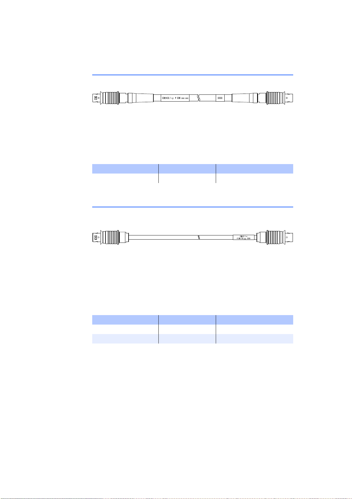
ETAS
8.2.3 CBE430.1 Cable
Fig. 8-13 CBE430.1 Cable
Cable for chaining ES4xx/ES63x/ES93x modules. Not compatible with ES59x,
ES6xx, ES11xx. For connecting this modules use CBE130 or CBE140 cable.
Robust, waterproof and dust-proof (IP67).
Temperature rated for: -40 °C to +125 °C / -40 °F to +257 °F
Product Length Order number
CBE430.1-0m45 0.45 m F 00K 104 923
8.2.4 CBE431.1 Cable
Fig. 8-14 CBE431.1 Cable
Highly flexible cable for chaining successive ES4xx/ES63x/ES93x modules.
Not compatible with ES59x, ES6xx, ES11xx. For connecting this modules use
CBE130 or CBE140 cable.
Robust, waterproof and dust-proof (IP67).
Temperature rated for: -40 °C to +125 °C / -40 °F to +257 °F
Product Length Order number
CBE431.1-0m14 0.14 m F 00K 105 676
CBE431.1-0m30 0.30 m F 00K 105 685
ES415.1 - User’s Guide 93
Page 94
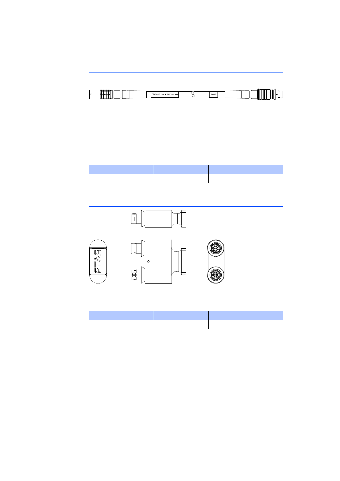
8.2.5 CBEX400.1 Cable
Fig. 8-15 CBEX400.1 Cable
Ethernet extension cable to increase the length of ES4xx/ES63x/ES93x Ethernet
cables. Can also be used to connect ES4xx via PC, ES600 or ES1135 alternatively
while keeping cable installation through bulkhead.
Robust, waterproof and dust-proof (IP67).
Temperature rated for: -40 °C to +125 °C / -40 °F to +257 °F
Product Length Order number
CBEX400.1-3 3 m F 00K 105 294
ETAS
8.2.6 ES4xx_BRIDGE
Fig. 8-16 ES4xx Bridge
Ethernet bridge connecting blocked ES400 modules. Facilitates very compact
measurement setups. IP67 compliant.
Product Order number
ES4xx_BRIDGE F 00K 105 684
ES415.1 - User’s Guide94
Page 95
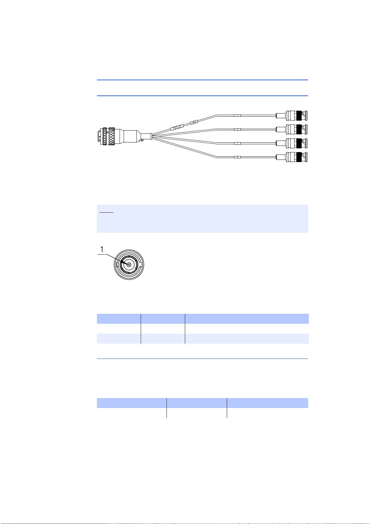
ETAS
Note
8.3 Cable for the Connection "Sensor"
8.3.1 CBAV400.1 Cable
Fig. 8-17 CBAV400.1 Cable
The CBAV400.1 cable consists of four identical cable sections, marked n=1 to
n=4. Each cable section [n] is assigned to an ES4xx measurement channel [n] and
wired according to the same scheme.
The sensor supply voltage of the module cannot be used if the cable
CBAV400.1 is used.
Fig. 8-18 Connection „Sensor“ (one Cable Section)
The assignment of the connections of the BNC connector of a cable section to
the signals of a measurement channel [n] is shown in the table.
Pin Signal Meaning
1 (inside) CH[n] In+ Measurement channel [n], input (+)
Outside CH[n] In- Measurement channel [n], input (-)
Notes about the Application
If you replaced modules with BNC cabling with ES4xx modules in your measuring
setup, the use of these adapter cables enables you to continue using the existing
cabling of your measuring setup.
Temperature rated for: -40 °C to +125 °C
Product Length Order number
CBAV400.1-0m3 0.3 m F 00K 104 916
ES415.1 - User’s Guide 95
Page 96
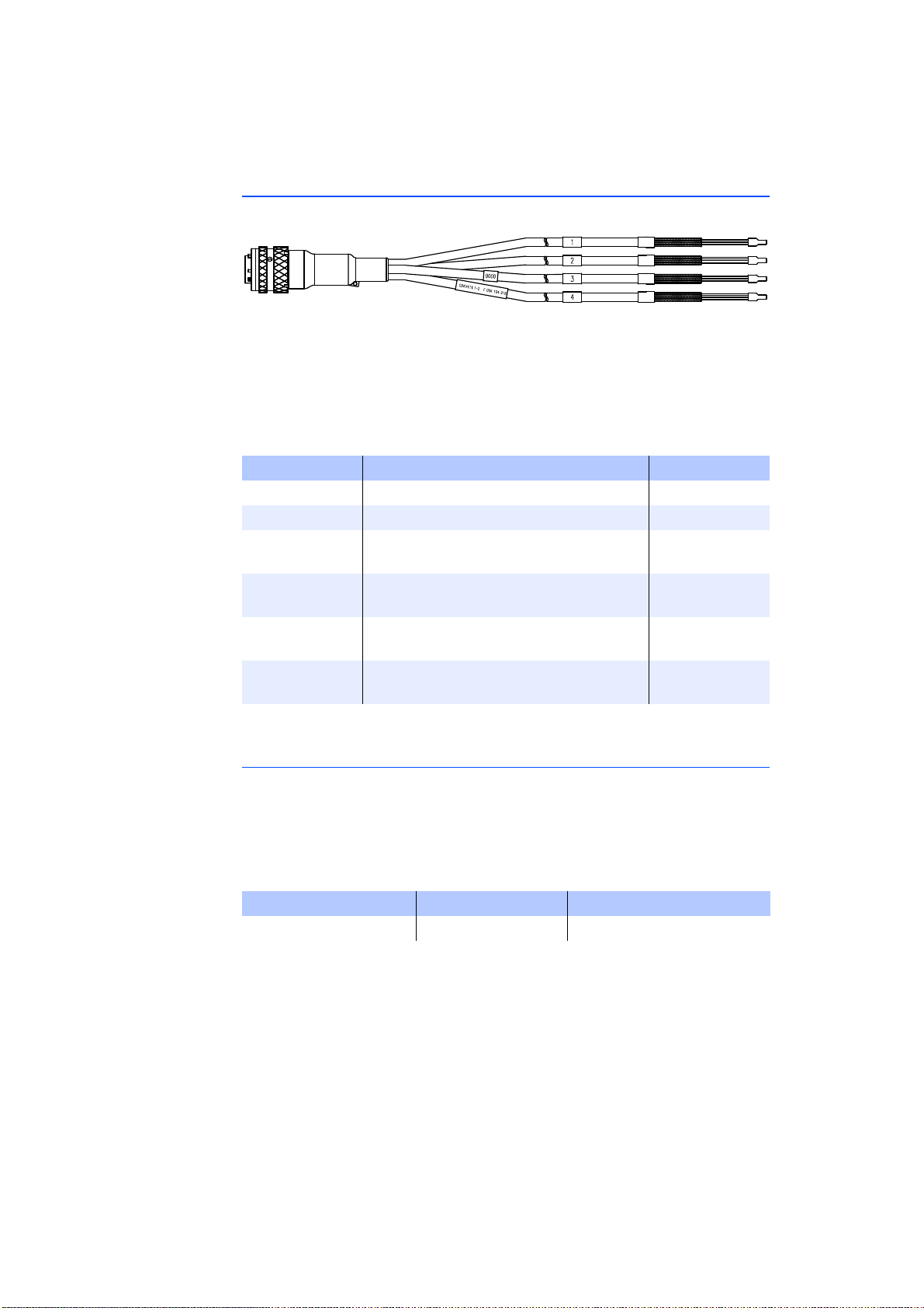
8.3.2 CBAV411.1 Cable
Fig. 8-19 CBAV411.1 Cable
The CBAV411.1 cable consists of four identical cable sections, marked n=1 to
n=4. Each cable section [n] is assigned to an ES4xx measurement channel [n] and
wired according to the same scheme.
The assignment of the cable connections of a cable section to the signals of a
measurement channel [n] is shown in the table.
Signal Meaning Color
CH[n] In+ Measurement channel [n], input (+) Green
CH[n] In- Measurement channel [n], input (-) Yellow
CH[n] S+ Measurement channel [n], sensor supply
CH[n] SGND Measurement channel [n], sensor supply
CH[n] TEDS+ Measurement channel [n], interface TEDS
CH[n] TEDS- Measurement channel [n], interface TEDS
(+)
(GND)
*)
(+)
*)
(-)
ETAS
Brown
Pink
Gray
White
*)
TEDS acc. IEEE1451.4
Notes about the Application
With the universal cable CBAV411.1, sensors or measuring transducers can be
connected to the ES4xx module.
You can customize the open connection of sensor cable CBAV411.1 and adapt it
to the specific plug connector system of your measuring setup.
Temperature rated for: -40 °C to +125 °C
Product Length Order number
CBAV411.1-2 2 m F 00K 104 918
ES415.1 - User’s Guide96
Page 97
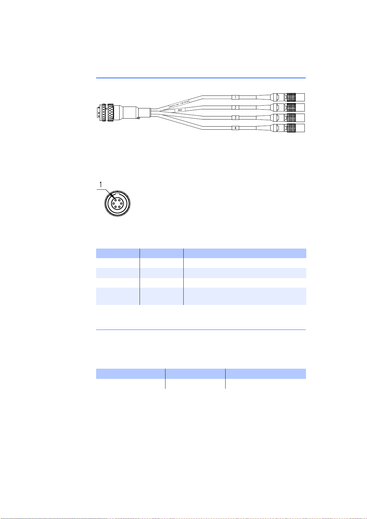
ETAS
8.3.3 CBAV413.1 Cable
Fig. 8-20 CBAV413.1 Cable
The CBAV413.1 cable consists of four identical cable sections with LEMO plugs,
marked n=1 to n=4. Each cable section [n] is assigned to an ES4xx measurement
channel [n] and wired according to the same scheme.
Fig. 8-21 Connection „Sensor“ (one Cable Section)
The assignment of the connections of the LEMO connector of a cable strand to
the signals of a measurement channel [n] is represented in the table.
Pin Signal Meaning
1 CH[n] In+ Measurement channel [n], input (+)
2 CH[n] In- Measurement channel [n], input (-)
4 CH[n] S+ Measurement channel [n], sensor supply (+)
5 CH[n] SGND Measurement channel [n], sensor supply
GND *)
*): connected with operating voltage Ground
Notes about the Application
If you replaced IPETRONIK M-SENS modules with ES4xx modules in your measuring setup, the use of these adapter cables enables you to continue using the
existing cabling of your measuring setup.
Temperature rated for: -40 °C bis +125 °C
Product Length Order number
CBAV413.1-0m3 0.3 m F 00K 105 682
ES415.1 - User’s Guide 97
Page 98
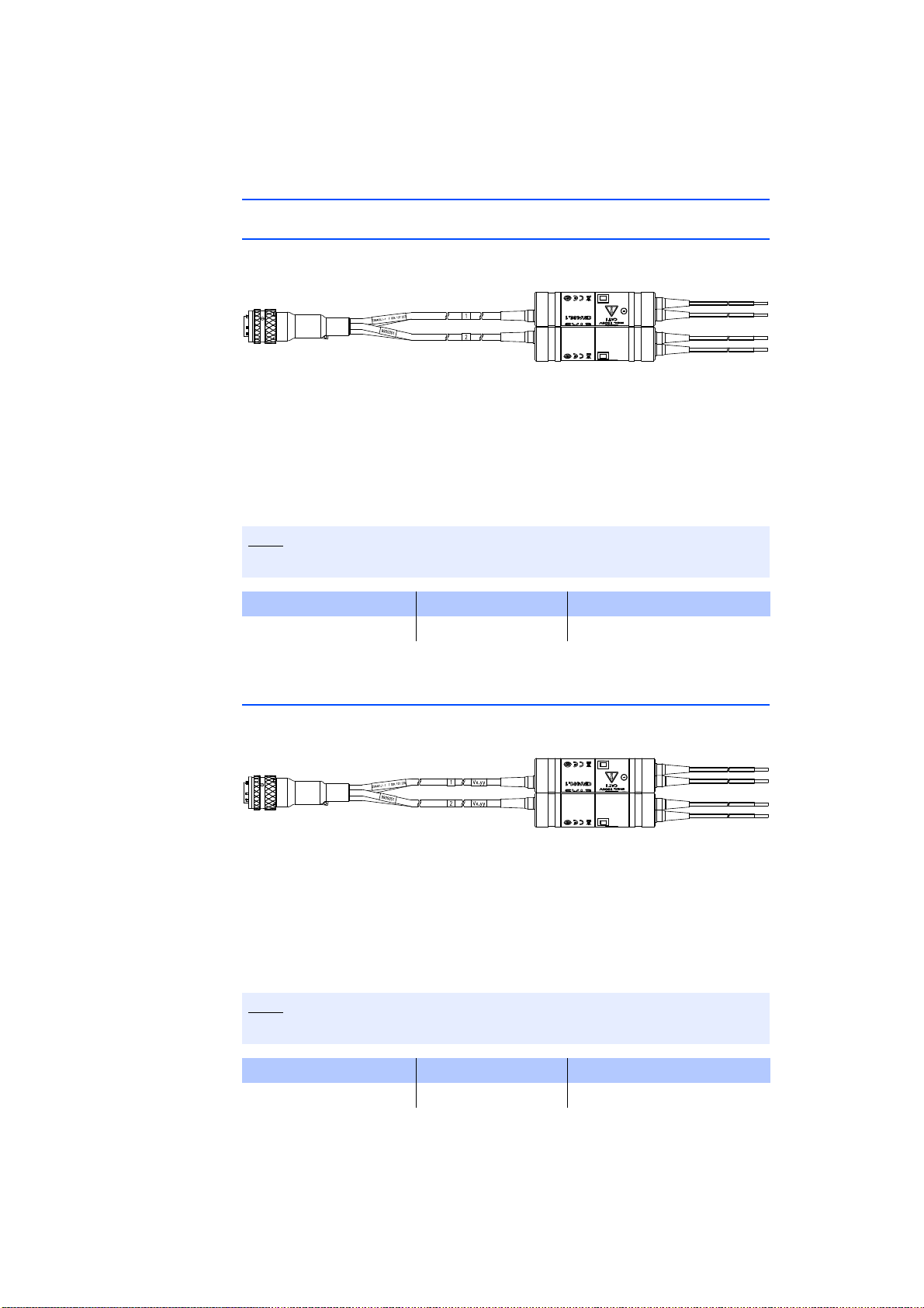
8.4 Measurement Probes and Cables
Note
Note
8.4.1 CBN400.1 Isolating Measurement Probe
Fig. 8-22 CBN400.1 Isolating Measurement Probe
The CBN400.1 Isolating Measurement Probe for use with the ES411.1/ ES415.1
module offers four input channels for voltages up to +/-1000 V DC, a separate
signal conditioning for each channel with voltage reduction and isolation (max.
+/-1000 V DC). The cable meets the safety standard EN 61010-1.
Temperature rated for: -40 to +85°C
ETAS
For additional information, see the user's guide of the product.
Product Length Order number
CBN400.1-1 1 m F 00K 107 227
8.4.2 CBN401.1 Isolating Measurement Probe
Fig. 8-23 CBN401.1 Isolating Measurement Probe
The CBN401.1 Isolating Measurement Probe for use with the ES411.1/ ES415.1
module offers four input channels for voltages up to +/-10 V DC, a separate
signal conditioning for each channel with voltage reduction and isolation (max.
+/-1000 V DC). The cable meets the safety standard EN 61010-1.
Temperature rated for: -40 to +85°C
For additional information, see the user's guide of the product.
Product Length Order number
CBN401.1-1 1 m F 00K 107 228
ES415.1 - User’s Guide98
Page 99
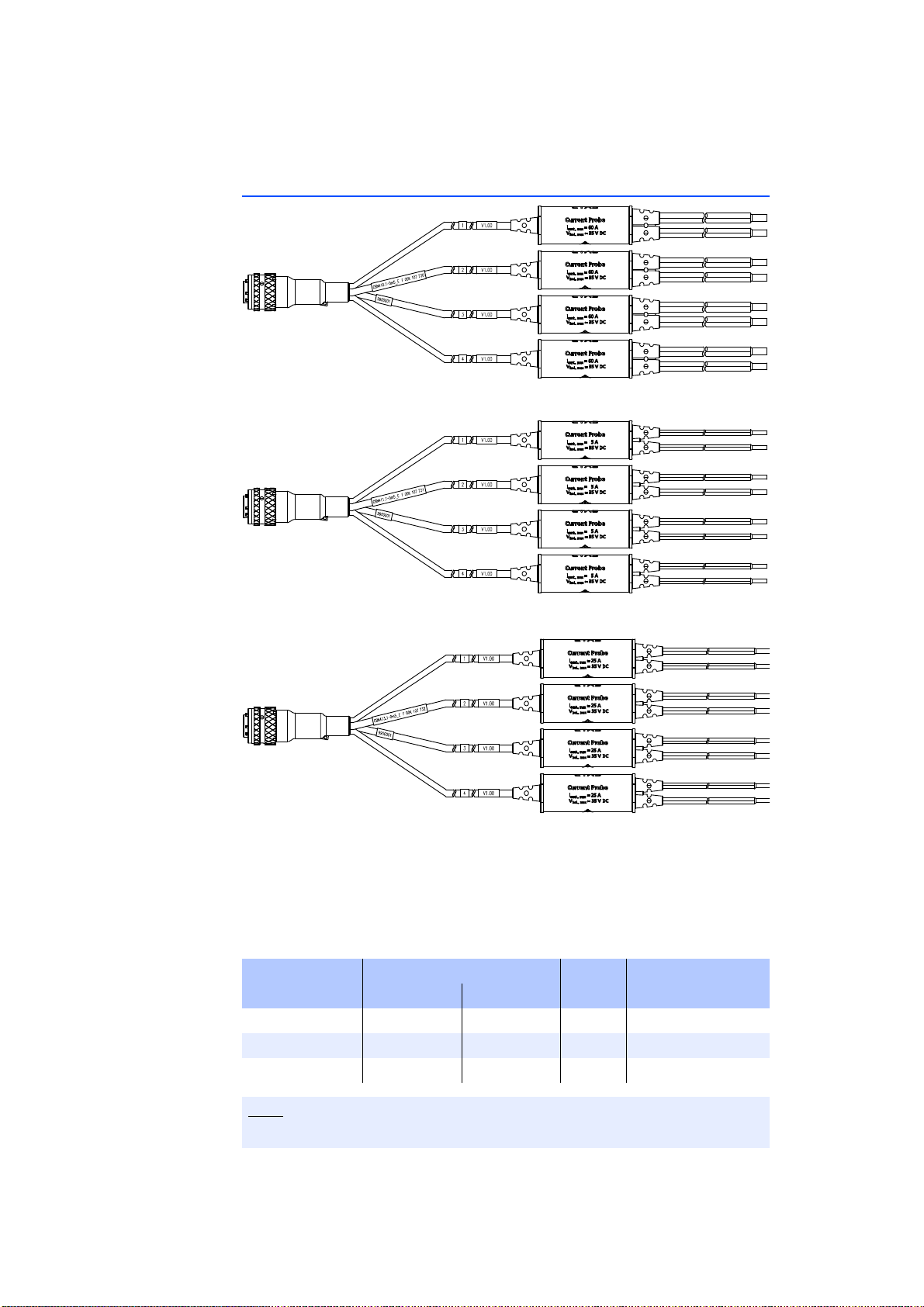
ETAS
Note
8.4.3 CBN41x.1 Current Probe
Fig. 8-24 CBN410.1 Current Probe
Fig. 8-25 CBN411.1 Current Probe
Fig. 8-26 CBN413.1 Current Probe
The CBN41x.1 Current Probe consists of four identical active current measuring
channels that are integrated in a splitter cable and designed for the combined
use with the ES411.1 / ES415.1 A/D module.
Application area: Measuring high currents
Temperature rated for: -40 to +85°C
Product Measurement Range Length Order number
Short-Term Continuous
CBN410.1-0m5 ±100 A ±60 A 0.5 m F 00K 107 722
CBN411.1-0m5 ±5 A ±5 A 0.5 m F 00K 107 723
CBN413.1-0m5 ±30 A ±25 A 0.5 m F 00K 107 724
For additional information, see the user's guide of the product.
ES415.1 - User’s Guide 99
Page 100
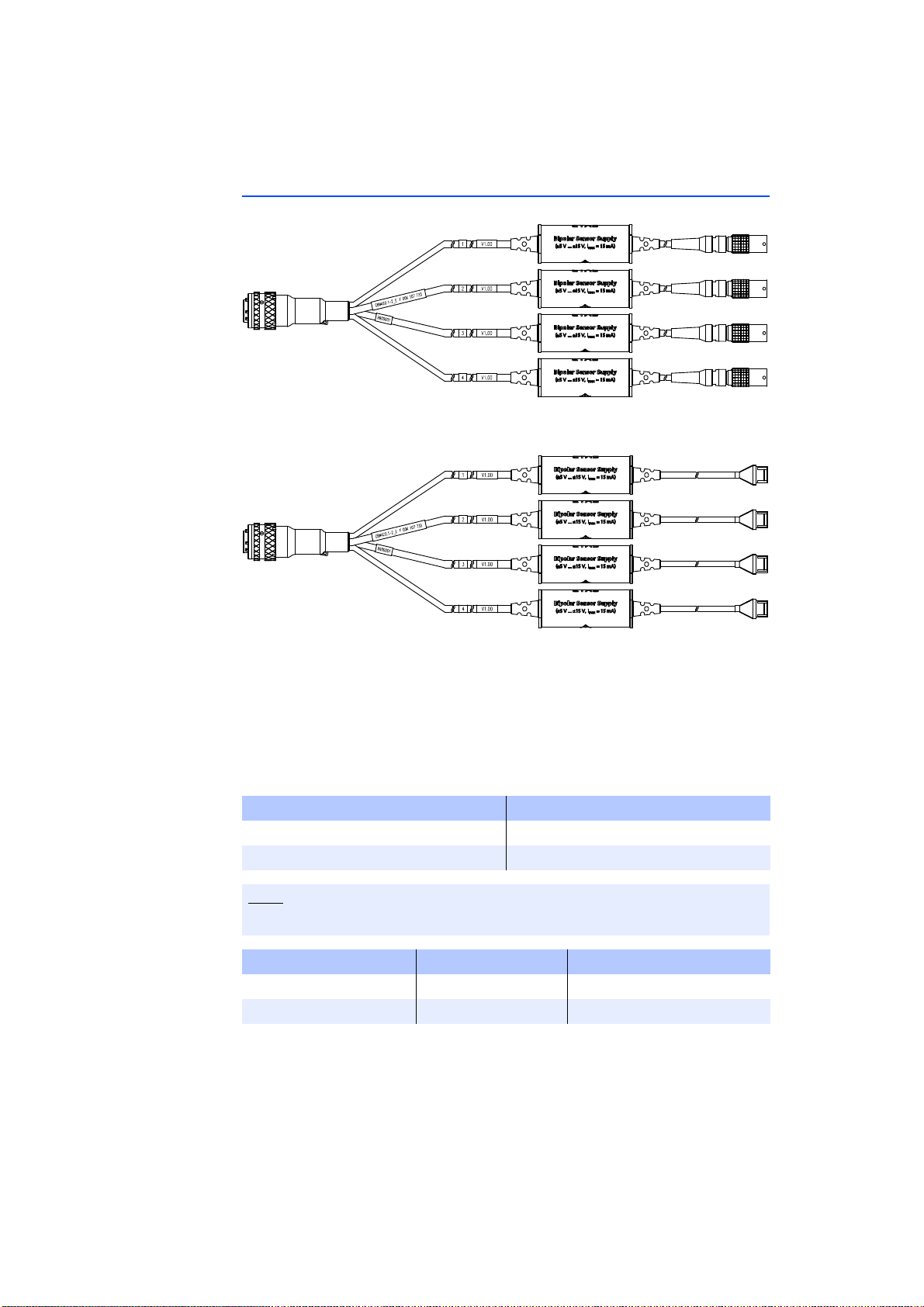
8.4.4 CBN42x.1 Sensor Cable
Note
Fig. 8-27 CBN420.1 Sensor Cable
ETAS
Fig. 8-28 CBN422.1 Sensor Cable
The CBN42x.1 Sensor Cable Providing Bipolar Sensor Supply consists of four
identical active current measuring channels that are integrated in a splitter cable
and designed for the combined use with the ES411.1 / ES415.1 A/D module.
Application area: potential-free measuring of high currents with current transformers from LEM (series HTR) or comparable current transformers and with
other sensors with bipolar supply voltage.
Product Sensor connection
CBN420.1 LEMO 1B PHG
CBN422.1 Molex 51191
For additional information, see the user's guide of the product.
Product Length Order number
CBN420.1-2m 2 m F 00K 107 564
CBN422.1-2m 2m F 00K 107 566
ES415.1 - User’s Guide100
 Loading...