

Page 1
2017-04-19
EN
0000000282
V.003
3.38.1
1910
93108-002
PelletsCompact
20-32 kW
Operation
Page 2

ETA Heiztechnik
Gewerbepark 1
A-4716 Hofkirchen an der Trattnach
Tel: +43 (0) 7734 / 22 88 -0
Fax: +43 (0) 7734 / 22 88 -22
[email protected]
www.eta.co.at
Page 3

3
Contents
1 General . . . . . . . . . . . . . . . . . . . . . . . . . . . . . . . . . . . . . . . . . . . . . . . . . . . . . . . . . . . . . . . . . . . . . . . . . . . . . . 5
1.1 Preface. . . . . . . . . . . . . . . . . . . . . . . . . . . . . . . . . . . . . . . . . . . . . . . . . . . . . . . . . . . . . . . . . . . . . . . . . . 5
1.2 General information . . . . . . . . . . . . . . . . . . . . . . . . . . . . . . . . . . . . . . . . . . . . . . . . . . . . . . . . . . . . . . . . 5
1.3 Warranty, guarantee and liability . . . . . . . . . . . . . . . . . . . . . . . . . . . . . . . . . . . . . . . . . . . . . . . . . . . . . . 6
2 Description . . . . . . . . . . . . . . . . . . . . . . . . . . . . . . . . . . . . . . . . . . . . . . . . . . . . . . . . . . . . . . . . . . . . . . . . . . . 8
3 Safety . . . . . . . . . . . . . . . . . . . . . . . . . . . . . . . . . . . . . . . . . . . . . . . . . . . . . . . . . . . . . . . . . . . . . . . . . . . . . . 11
3.1 General information . . . . . . . . . . . . . . . . . . . . . . . . . . . . . . . . . . . . . . . . . . . . . . . . . . . . . . . . . . . . . . . 11
3.2 Safety devices . . . . . . . . . . . . . . . . . . . . . . . . . . . . . . . . . . . . . . . . . . . . . . . . . . . . . . . . . . . . . . . . . . . 11
4 Empty the ash box . . . . . . . . . . . . . . . . . . . . . . . . . . . . . . . . . . . . . . . . . . . . . . . . . . . . . . . . . . . . . . . . . . . . 13
5 ETAtouch controller. . . . . . . . . . . . . . . . . . . . . . . . . . . . . . . . . . . . . . . . . . . . . . . . . . . . . . . . . . . . . . . . . . . 15
5.1 Getting to know the control system . . . . . . . . . . . . . . . . . . . . . . . . . . . . . . . . . . . . . . . . . . . . . . . . . . . 15
5.1.1 User interface . . . . . . . . . . . . . . . . . . . . . . . . . . . . . . . . . . . . . . . . . . . . . . . . . . . . . . . . . . . . . 16
5.1.2 Text menu . . . . . . . . . . . . . . . . . . . . . . . . . . . . . . . . . . . . . . . . . . . . . . . . . . . . . . . . . . . . . . . . 17
5.1.3 Integrated help. . . . . . . . . . . . . . . . . . . . . . . . . . . . . . . . . . . . . . . . . . . . . . . . . . . . . . . . . . . . . 17
5.1.4 Messages . . . . . . . . . . . . . . . . . . . . . . . . . . . . . . . . . . . . . . . . . . . . . . . . . . . . . . . . . . . . . . . . 18
5.1.5 Inputs and outputs . . . . . . . . . . . . . . . . . . . . . . . . . . . . . . . . . . . . . . . . . . . . . . . . . . . . . . . . . . 19
5.1.6 Getting started . . . . . . . . . . . . . . . . . . . . . . . . . . . . . . . . . . . . . . . . . . . . . . . . . . . . . . . . . . . . . 20
5.1.7 meinETA remote control . . . . . . . . . . . . . . . . . . . . . . . . . . . . . . . . . . . . . . . . . . . . . . . . . . . . . 25
5.2 [Boiler] function block - PelletsCompact 20-32 kW . . . . . . . . . . . . . . . . . . . . . . . . . . . . . . . . . . . . . . . 28
5.2.1 Operating elements . . . . . . . . . . . . . . . . . . . . . . . . . . . . . . . . . . . . . . . . . . . . . . . . . . . . . . . . . 28
5.2.2 Text menu - Adjustable parameters. . . . . . . . . . . . . . . . . . . . . . . . . . . . . . . . . . . . . . . . . . . . . 29
5.3 [Buffer] function block. . . . . . . . . . . . . . . . . . . . . . . . . . . . . . . . . . . . . . . . . . . . . . . . . . . . . . . . . . . . . . 32
5.3.1 Setting the buffer charging times. . . . . . . . . . . . . . . . . . . . . . . . . . . . . . . . . . . . . . . . . . . . . . . 33
5.3.2 Buffer with solar heating system . . . . . . . . . . . . . . . . . . . . . . . . . . . . . . . . . . . . . . . . . . . . . . . 33
5.3.3 Buffer as a combination tank . . . . . . . . . . . . . . . . . . . . . . . . . . . . . . . . . . . . . . . . . . . . . . . . . . 34
5.3.4 Text menu - Adjustable parameters. . . . . . . . . . . . . . . . . . . . . . . . . . . . . . . . . . . . . . . . . . . . . 36
5.4 [Hot water tank] function block. . . . . . . . . . . . . . . . . . . . . . . . . . . . . . . . . . . . . . . . . . . . . . . . . . . . . . . 42
5.4.1 Setting the hot water charging times . . . . . . . . . . . . . . . . . . . . . . . . . . . . . . . . . . . . . . . . . . . . 43
5.4.2 Text menu - Adjustable parameters. . . . . . . . . . . . . . . . . . . . . . . . . . . . . . . . . . . . . . . . . . . . . 43
5.5 [Fresh water module] function block . . . . . . . . . . . . . . . . . . . . . . . . . . . . . . . . . . . . . . . . . . . . . . . . . . 46
5.5.1 Setting the hot water charging times . . . . . . . . . . . . . . . . . . . . . . . . . . . . . . . . . . . . . . . . . . . . 47
5.5.2 Text menu - Adjustable parameters. . . . . . . . . . . . . . . . . . . . . . . . . . . . . . . . . . . . . . . . . . . . . 47
5.6 [Heating circuit] function block . . . . . . . . . . . . . . . . . . . . . . . . . . . . . . . . . . . . . . . . . . . . . . . . . . . . . . . 50
5.6.1 Operating elements . . . . . . . . . . . . . . . . . . . . . . . . . . . . . . . . . . . . . . . . . . . . . . . . . . . . . . . . . 51
5.6.2 Setting the heating time slots. . . . . . . . . . . . . . . . . . . . . . . . . . . . . . . . . . . . . . . . . . . . . . . . . . 51
5.6.3 The heating curve . . . . . . . . . . . . . . . . . . . . . . . . . . . . . . . . . . . . . . . . . . . . . . . . . . . . . . . . . . 52
5.6.4 Text menu - Adjustable parameters. . . . . . . . . . . . . . . . . . . . . . . . . . . . . . . . . . . . . . . . . . . . . 57
5.7 [Solar] function block . . . . . . . . . . . . . . . . . . . . . . . . . . . . . . . . . . . . . . . . . . . . . . . . . . . . . . . . . . . . . . 58
5.7.1 Solar heating system with one tank. . . . . . . . . . . . . . . . . . . . . . . . . . . . . . . . . . . . . . . . . . . . . 58
5.7.2 Solar heating system with 2 tanks . . . . . . . . . . . . . . . . . . . . . . . . . . . . . . . . . . . . . . . . . . . . . . 59
5.7.3 Solar heating system for buffer with 2 internal coils. . . . . . . . . . . . . . . . . . . . . . . . . . . . . . . . . 59
5.7.4 Solar heating system with external heat exchanger . . . . . . . . . . . . . . . . . . . . . . . . . . . . . . . . 60
5.7.5 Solar heating system with external heat exchanger and stratified charging valve . . . . . . . . . 61
5.7.6 Text menu - Adjustable parameters. . . . . . . . . . . . . . . . . . . . . . . . . . . . . . . . . . . . . . . . . . . . . 62
Page 4

5.8 [External heat source] function block . . . . . . . . . . . . . . . . . . . . . . . . . . . . . . . . . . . . . . . . . . . . . . . . . . 64
5.8.1 Text menu - Adjustable parameters. . . . . . . . . . . . . . . . . . . . . . . . . . . . . . . . . . . . . . . . . . . . . 65
5.9 [Pellet store] function block . . . . . . . . . . . . . . . . . . . . . . . . . . . . . . . . . . . . . . . . . . . . . . . . . . . . . . . . . 66
5.10 [Pellet store with switch unit] function block. . . . . . . . . . . . . . . . . . . . . . . . . . . . . . . . . . . . . . . . . . . . . 68
5.10.1 Text menu - Adjustable parameters. . . . . . . . . . . . . . . . . . . . . . . . . . . . . . . . . . . . . . . . . . . . . 68
6 Emission measurement. . . . . . . . . . . . . . . . . . . . . . . . . . . . . . . . . . . . . . . . . . . . . . . . . . . . . . . . . . . . . . . . 69
7 Low-emission operation . . . . . . . . . . . . . . . . . . . . . . . . . . . . . . . . . . . . . . . . . . . . . . . . . . . . . . . . . . . . . . . 71
8 Heating water . . . . . . . . . . . . . . . . . . . . . . . . . . . . . . . . . . . . . . . . . . . . . . . . . . . . . . . . . . . . . . . . . . . . . . . . 72
8.1 Water hardness . . . . . . . . . . . . . . . . . . . . . . . . . . . . . . . . . . . . . . . . . . . . . . . . . . . . . . . . . . . . . . . . . . 72
8.2 Refilling . . . . . . . . . . . . . . . . . . . . . . . . . . . . . . . . . . . . . . . . . . . . . . . . . . . . . . . . . . . . . . . . . . . . . . . . 73
4 www.eta.co.at
Page 5

General Preface
5
1 General
1.1 Preface
Dear customer,
This user manual provides important information and
instructions, to ensure safe and satisfactory operation
of your product. Please take the time to look through it.
Warranty and guarantee
You should also read the "Conditions for warranty,
guarantee, liability" (see 1.3 "
liability") carefully. As a rule, these conditions will be
satisfied by a professional heating technician. Nevertheless, inform the technician of our warranty
conditions. All of the requirements we impose are
intended to prevent damage that neither you nor we
wish to occur.
Read the user manual
Please read the user manual carefully before starting
up the system. This is the only way to ensure that you
can operate your new boiler efficiently and with
minimum environmental impact.
Take advantage of the knowledge and skills of an
expert
Only allow an expert to assemble, install and
commission the equipment and carry out the basic
boiler settings. Insist on receiving an explanation and
training on how your new boiler functions and how to
operate and maintain it.
Extended warranty
We grant an extended warranty if the product is commissioned by an authorised partner company or by our
own customer service. In this regard, please note the
warranty conditions applicable at the time of purchase.
Warranty, guarantee and
ETA boiler. A LAN cable is required for the connection
from the ETAtouch control system to the internet
modem.
Details for the remote control can be found in the
manual "Communication platform meinETA".
Details for the connection of the LAN cable can be
found in the boilers installation manual.
1.2 General information
Copyright
All contents of this document are property of ETA
Heiztechnik GmbH and are protected by copyright.
Any reproduction, transfer to third parties or use for
other purposes is prohibited without written permission
from the owner.
Subject to technical changes
We reserve the right to make technical modifications
without notice. Printing and typesetting errors or
changes of any kind made in the interim are not cause
for claims. Individual configurations depicted or
described here are only available optionally. In the
event of contradictions between individual documents
regarding delivery scope, the information in ou r current
price list applies.
Software Description
The software version described in this documentation
corresponds to the version valid at the time of publication. The software version installed on your product
may differ from that described in this documentation.
A software update to a more recent version can
always be performed. With the appropriate authorisation, the required files can be found at
"www.eta.co.at".
Service agreement
You can ensure the best care for your heating system
by taking out a service agreement with one of our
certified contractors or our own customer service.
Remote control of the boiler via the internet
The remote control enables you to operate your ETA
boiler remotely via your own network (VNC Viewer) or
the internet <www.meinETA.at> using a PC,
smartphone or tablet, as though you were standing
right in front of the ETAtouch control system of your
Explanation of symbols
Instructions and information
Layout of safety instructions
SIGNAL WORD!
Type and source of danger
Possible effects
• Measures for avoiding the danger
Types of safety instruction
Page 6

Warranty, guarantee and liability General
CAUTION!
On non-compliance with this safety instruction, there is
a risk of material damage.
WARNING!
On non-compliance with this safety instruction, there is
a risk of physical injury.
DANGER!
On non-compliance with this safety instruction, there is
a risk of major physical injury .
1.3 Warranty, guarantee and liability
Requirements
We can only accept liability for the function of our
products if they are correctly installed and operated.
This is only possible if the conditions below are
complied with.
Maximum of 2,000 hours at full load per year
The boiler described in this user manual may only be
used for heating and producing hot water , with no more
than 2,000 full-load hours annually.
Installation in a dry room
For set-up, a dry room is required. In particular, only
condensation dryers may be used as clothes dryers in
the same room.
Observe local building and fire safety regulations
Local building and fire safety regulations must be
observed.
Connecting pipe to chimney
The connecting pipe to the chimney must be a
moisture-resistant stainless steel flue pipe with
120 mm diameter (maximum diameter 130 mm) and at
least 3 cm of insulation. For lengths over 2 m, correspondingly more insulation is needed.
Suitable fuel
The boiler is suitable for use with wood pellets
according to EN ISO 17225-2:2014, quality class A1,
ENplus-A1. Operation with unsuitable fuels, in
particular those containing halogens (chlorine) or highslag pellets such as from grain waste, is not permitted.
Ensure supply air is free from aggressive
substances
The air supplied to the boiler must be free from
aggressive substances such as chlorine and fluorine
from solvents, cleaning agent s, a dhesive s a nd p ropellants, or ammonia from cleaning agents, to prevent
corrosion of the boiler and chimney.
Permissible water hardness
Water is the intended heat-transfer medium. For
special anti-frost requirements, up to 30% glycol may
be added. Softened water is required for the initial fillup of the heating system and for refilling after repairs.
Addition of hard water should be minimised to limit
limescale build-up in the boiler.
In order to protect the boiler from calcification, the
water hardness of the heating water must be
taken into account. Observe the indications outlined in
ÖNORM H 5195-1. Details can be found in chapter 8
"Heating water".
pH value between 8 and 9
The pH value of water used to fill the heating system
must be between 8 and 9.
Use a sufficient number of shut-off valves
Set enough shut-off valves to avoid bleeding large
amounts of water during repairs. Any leaks in the
system must be repaired at once.
Provide a sufficiently large expansion tank or a
pressure maintaining device
To prevent air from being drawn in while the system is
cooling, the heating system professional must provide
a sufficiently large expansion tank or a pressure
maintaining device.
Open expansion tanks must not be used.
Sufficient power
Continuous operation with heat consumption below
the minimum specified on the type plate is only
permitted with a buffer storage tank of sufficient size.
Expanding the control system
Only components provided by us may be used for
expanding the control system, unless these are
generally available standard devices, such as thermostats.
6 www.eta.co.at
Page 7

General Warranty, guarantee and liability
7
Regularly perform cleaning and maintenance
Cleaning and maintaining the product is essential. Th e
required steps and intervals are eith er contained in this
documentation or included as a separate document.
Repairs
Repairs are only permitted using spare parts provided
by us. The only exceptions are common standardised
parts such as electrical fuses or fastening materials, as
long as they possess the required features and do not
restrict the functionality of the system.
Proper installation
The installing contractor is liable for proper installation
according to the corresponding installation instructions
and the relevant rules and safety regulations. If you as
customer have installed the heating system partly or
entirely without relevant training and in particular
without up-to-date practical experience, without having
the installation checked by a trained and responsible
expert, we exclude defects in our delivery and consequential damages resulting from this cause from our
warranty, guarantee and liability.
Repair of defects
For repairs of defects carried out b y the customer or by
a third party, ETA shall only bear the costs or remain
obligated by warranty if this work was approved in
writing in advance by the customer service of ETA
Heiztechnik GmbH.
No tampering with boiler safety devices
Boiler safety devices such as those mentioned below
must not be tampered with: Temperature monitoring
and control devices, safety temperature limiters, safety
valves and thermal discharge valves.
Page 8

2 Description
Operating elements of the boiler
Description
1 Screen for the ETAtouch control system
2 Release button for safety temperature limiter
(STB)
3 Mains switch (symbol )
4 Maintenance switch (symbol )
5 Boiler door
6 Poker for cleaning
7 Lever to lock the ash box in boiler
8 Ash box
8 www.eta.co.at
Page 9
Description
9
Explanation of the maintenance switch
The maintenance switch on the boiler is needed for
performing maintenance with the aid of the [Maintenance] function in the ET Atouch contr ol system. This
displays the individual maintenance steps on the boiler
screen.
With this variant the heating mode is stopped, but
the boiler remains on at the mains switch. So that
all drives are disconnected, the safety chain of the
boiler is disrupted with the maintenance switch. The
screen will display a message when it is time to actuate
the maintenance switch.
Fig. 2-1: Maintenance switch
The maintenance switch is marked with the
symbol and has two settings.
• "1" = regular operation
This is the standard position of the maintenance
switch. The boiler can execute heating mode in this
position.
• "0" = maintenance mode
In this position, all drives are disconnected to
perform maintenance. The circuit boards,
however, are still live.
To access maintenance, switch to settings in the boiler
function block ( [Settings] button) and then select
the function [Maintenance].
Fig. 2-2: Overview (example)
You can also access this overview by pressing
the maintenance switch. Also when the message
appears that maintenance of the boiler is required.
In the overview the different maintenance intervals ar e
listed in the upper area. This includes the maintenance
already carried out. With the button, information
about the selected maintenance is displayed.
Maintenance that you can carry out as an end
customer is labelled with the symbol. All others are
reserved for specialists and require authorisation.
Press the button to start the maintenance. The
individual steps are displayed on the screen. You can
switch to the next or the previous screen respectively
with the arrow keys on the left and right side of the
screen.
Display maintenance steps on the screen
With this boiler, the maintenance steps can also be
displayed on the ET Atouch control system screen. The
required activities will be explained to you step-by-step
and supplemented with detailed graphics. Each
maintenance is saved and the details can be viewed at
any time. So you can maintain a long-term overview of
the maintenance carried out. Of course, the
maintenance can also be carried out using the service
guide, without the support of the ETAtouch control
system.
Fig. 2-3: Maintenance step (example)
Page 10

Follow the on-screen instructions and carry out all
steps carefully. Enter your name at the end of
maintenance ( button) and save the maintenance
with the button.
Fig. 2-4: End of maintenance
To end maintenance prematurely, press the right
arrow key several times until you get to the end.
There you can end the maintenance with the
button. Cancellation during a maintenance step is not
possible.
Description
Adjust the hinges for the screen
The ease of movement of the hinges to swivel the
screen can be adjusted with the Allen key supplied. If
the screen does not remain in its desired position,
tighten the screws on the hinges a little.
Fig. 2-5: Hinges
Clean panels
If necessary, clean the panels of the boiler and the
ETAtouch screen with a moist cloth.
Under no circumstances use aggressive
solvents, chemicals or scouring agents. They can
lead to stress cracks and damage.
10 www.eta.co.at
Page 11

Safety General information
11
3 Safety
3.1 General information
Operation only by trained personnel
The product may be operated by trained adults only.
Training may be provided by the heating technician or
our customer service. Please read the associated documentation carefully in order to avoid errors during
operation and maintenance.
Persons who lack experience and knowledge as well
as children may not operate, clean, or maintain the
product.
Keep children away from the pellet store
Children must be kept away from the pellet store. It is
a good idea to lock the door to the pellet store. The
door handle on the inside of the pellet store must not
be removed. It must be possible to open the door from
the inside in an emergency.
Keep fire extinguishers in a clearly visible location
In Austria, the minimum requirement is an
ABC powder extinguisher with 6 kg. An AB foam extinguisher with 9 litres, which produces less damage
when used, is preferable. The fire exting uisher sho uld
be kept outside the boiler room, visible and easily
accessible.
Storage of ash
The ash must be kept in non-flammable containers
with covers for cooling. Never put hot ash into the
waste bin!
Emergency stop switch for the boil e r
In Austria, heating systems installed in boiler rooms
must be equipped with an emergency stop switch. The
switch must be situated immediately outside the
access door and clearly marked. For boile r roo ms that
are only accessible from outdoors, these switches may
also be within the boiler rooms, immediately next to the
access doors.
Fig. 3-1: Fire extinguisher
In Germany and Switzerland, fire extinguishers are not
required for heating systems in private residences. In
spite of this, we recommend having one in the house.
Fig. 3-2: Emergency stop switch
A single-pole emergency stop switch is integrated into
the boiler's safety chain. When actuated, it interrupts
the supply of combustion air and fuel. The pumps
continue running to cool the boiler.
3.2 Safety devices
Pump safety run, automatic heat dissipation at
overtemperature
If the boiler temperature exceeds 90°C (factory setting)
for any reason, the pump safety run will start. All
heating pumps and boiler pumps that are connected to
the boiler control system are switched on to dissipate
heat from the boiler.
This action prevents the boiler temperature from rising
further and triggering further safety devices such as
the safety temperature limiter.
Page 12

Safety devices Safety
Heat dissipation is limited by the selected
maximum flow temperature in the heating circuits
and the target hot water temperature.
Safety shutdown by safety temperature limiter
For additional safety against boiler overheating, a
safety temperature limiter is built into the boiler. When
a boiler temperature of 105°C (toleran ce 100 to 106°C)
is reached, the power supply to the draught fan and th e
fuel intake is interrupted. If the boiler temperature
decreases below 70°C again, the safety temperature
limiter can be manually released for a restart of the
boiler.
Safety valve against overpressure
A safety valve with 3 bar opening pressure has already
been installed on the boiler at the factory. If solar or
other heat sources provide energy to the buffer
storage tank via a heat exchanger, a safety valve
(3 bar maximum) is also required on the buf fer storage
tank.
Fig. 3-3: Safety valve
Normally an expansion tank that is too small or
defective, or blocked heating lines, are the cause for
activation of the safety valve. The safety valve should
be
installed at the highest point of the heat producer or i
n the flow pipe close to the heat producer.
DANGER!
Safety valve outlet
The safety valve outlet must be directed to the ground
in a pipe so nobody is endangered by hot water or
steam.
The safety valve outlet must be directed to the
sewer via a clearly visible, open route (siphon
funnel), so that malfunctions, especially a failure of
the safety valve to close, can be detected. If no
sewer connection is available, the outlet must be
directed to the ground in a pipe.
12 www.eta.co.at
Page 13

Empty the ash box
13
4 Empty the ash box
Stop heating
End the boiler's heating mode with the On/Off switch
in the boiler overview window. The boiler
performs an ember burnout and then changes to
[Switched off] mode. Press the [De-ash] button to
make the boiler perform a final de-ashing.
Empty the ash box and inspect the sea ls
Open the boiler door and fold the locking lever
forwards. Remove the ash box from the boiler.
Fig. 4-1: Locking lever
The ash box can be lifted on the bottom with a
handcart and transported.
Open the latch on the lid and empty the ash box.
Fig. 4-2: Lid
Check the ash for embers. Never put hot ash into
the waste bin!
Inspect the seal on the ash box lid for integrity, and
replace it if necessary.
Fig. 4-3: Seal
Page 14

Inspect the integrity of the ash box seals on the boiler,
replace them if necessary.
Fig. 4-4: Seals
Attaching the ash box to the boiler
Reattach the cover of the ash box and secure with the
fasteners. Push the ash box over the connection on
the boiler and attach it to the boiler with the locking
lever.
Empty the ash box
Fig. 4-5: Locking lever
Switching on the boiler
Switch the boiler back on with the On/Off
switch.
14 www.eta.co.at
Page 15

ETAtouch controller Getting to know the control system
15
5 ETAtouch controller
5.1 Getting to know the control
system
Get to know the control system
Take your time and read the following chapter
carefully. It describes the functions and settings of the
ETAtouch control for your heating system. If you are
familiar with these, it will be easier for you to make adjustements, even without consulting the manual.
Design of the control system
The individual components of the heating system, e.g.
buffer, hot water tank or heating circuit are shown in
the control system as "function blocks". These are
listed in the uppermost row on the screen. The
respective user interface is opened with a single tap of
the finger.
Fig. 5-1: ETAtouch control system function blocks
1 Currently selected function block
2 Other function blocks, e.g. hot water tank, heating
circuit, solar heating system
3 Scroll to other function blocks (displayed if not all
function blocks can be displayed simultaneously)
4 Help button. Details can be found in chapter 5.1.3
"Integrated help".
5 Settings of the selected function block
6 Date and time
7 Current outside temperature
8 Status of the remote control for the boiler (via
www.meinETA.at), see chapter 5.1.7 "
remote control"
9 System configuration
meinETA
Page 16
Getting to know the control system ETAtouch controller
Several views are available for each function block. To
switch between these, tap on the symbol at
the top left. The selection of views appears.
Fig. 5-2: Selection of views
1 User interface
2Text menu
3 Inputs and outputs menu
4 Messages menu
In the user interface, you can set the most
important and common settings. For example,
adjustment of the charging times, heating
times, room temperatures and operating modes are
contained in this list. Details can be found in chapter
User interface".
5.1.1 "
The parameters of a function block are
displayed in the text menu and can be
adjusted,if necessary, see chapter 5.1.2 "
menu".
The terminal assignment of individual
components, such as temperature sensors,
pumps and mixers, are visible within the input
and output menu, where they can be changed if
required. Also, for example, pumps and mixers can be
started in manual mode. This menu is intended for
specialists only. Details can be found in chapter 5.1.5
"Inputs and outputs".
Any hints, errors or faults are displayed in the
messages menu, see chapter 5.1.4
"Messages".
Text
5.1.1 User interface
The user interface
The user interface is always displayed by default. If
you are in a different view, switch to the user view by
tapping the symbol (upper left) and then
selecting .
In the user interface, you can set the most important
and common settings. The display is dependent on the
selected function block. The illustrated example shows
the user interface of a heating circuit with a room
sensor.
Fig. 5-3: Heating circuit user interface
1 Operating condition and information
2 Producer for the heating circuit.
Currently , the buf fer provides a flow temperature of
65 °C to the heating circuit.
3 On/Off switch for the heating circuit
= switched on
= switched off
4 Increase or decrease the room temperature
5 Function block settings.
In this menu, the settings and functions most
commonly used can be stored. For the heating
circuit, for example, the heating times and the
heating curve are adjusted here.
6 Graphic display of the heating times and room tem-
peratures settings
7 Different operating modes of the heating circuit
16 www.eta.co.at
Page 17

ETAtouch controller Getting to know the control system
17
5.1.2 Text menu
Adjust parameters in the text menu
To enter the text menu, tap in the upper left on the
symbol, followed by . In the text menu, the
required parameters for the control system of the
function block are listed. Modifiable parameters are
indicated by the symbol.
The default setting and the setting range are displayed
on the right side. The new value is entered with the
keypad, and stored by pressing the [Save] button.
Resetting to factory settings is done by pressing the
[Factory settings] button. To cancel and close the
window, tap the arrow on the left side of the screen.
Only modify parameters whose function you're
familiar with. Before making any changes, read
the relevant section of the user manual or configuration manual, or open the integrated help feature. If you
cannot find sufficient information about a parameter,
please consult a specialist.
Commonly used parameters can be found in the
settings
Commonly used parameters can be found in the
function block settings ( button). There, the
parameters are identified by the symbol and can be
adjusted by tapping. This saves you having to search
through the text menu for these parameters.
5.1.3 Integrated help
Fig. 5-4: Text menu
1 Parameter
2 Current value or setting
3 Editable parameter
Changing a parameter is simple. Select this and tap
the symbol. The settings window appears.
How to use the integrated help
Use the integrated help to find information. This
appears when the button is pressed. If help is
activated, annotations will appear in the user interface
in blue boxes.
Fig. 5-6: Activated help in the user interface
Fig. 5-5: Settings window
1 Factory setting and adjustment range
2 Reset to factory setting
3 Save and close
4 Cancel and close
Page 18

Getting to know the control system ETAtouch controller
Fields with additional line symbols on the right
side (example: ) indicate that further
information is available. Tap on the appropriate field
and a window with the description will open. Close the
window using the arrow on the left side.
Fig. 5-7: Description
The help function can also be accessed via the text
menu. A detailed description is available for all the
parameters displayed in blue writing. Just tap on a
parameter and a window will open with the descri ption.
Fig. 5-8: Activate help in the text menu
To disable help, press the button again.
5.1.4 Messages
An error message appears
If an error occurs, a symbol of the type of error appears
in the corresponding function block. This symbol is
also displayed at the bottom of the screen.
Fig. 5-9: Symbols when an error occurs
Types of errors and their meaning
• Notification
A notification does not interrupt operation, and
therefore no acknowledgement is req uired. Notifications inform the user, for example, that pump
anti-blocking protection has been activated.
• Warning
A warning is displayed on failure of a function
which is not absolutely essential for continued
operation. It can be acknowledged before the
cause of failure is remedied. However, it will
continue to be displayed until the cause has
actually been dealt with.
• Malfunction or alarm
An error or alarm stops operation. Some of these
can be acknowledged before the cause of the
problem is remedied. However, they will continue
to be displayed until the cause h as actually been
dealt with. Other errors and alarms can only be acknowledged after the cause has successfully been
remedied. Once an error or alarm has been
resolved and acknowledged, you must restart the
boiler or the affected function block.
18 www.eta.co.at
Page 19

ETAtouch controller Getting to know the control system
19
If the error symbol at the bottom of the screen is
tapped, a window appears. In this, the function block in
which the error occurred will be displayed.
Fig. 5-10: Display of the function blocks in which the error
occurred
If the function block is selected, the view changes to
the messages menu. By tapping the error, the error
description is displayed.
When authorization is given, the terminal
assignment can be changed. Also, manual mode
for, e.g. a pu mp or a mixer, is possible.
Below is an example of the function block of the
heating circuit. To view the terminal assignment, first
select the heating circuit. To access the inputs and
outputs menu, tap on the symbol, followed by
. An overview screen opens.
Fig. 5-12: Overview
Fig. 5-11 : Err or description
To acknowledge, press the [Acknowledge] button.
Depending on the nature of the fault, this either
remains visible or disappears.
You can also switch to the messages menu to
display any errors. Just tap on the
symbol and then select .
5.1.5 Inputs and outputs
See terminal assignment of individual
components
The terminal assignments of the individual
components of the selected function block are
displayed in the inputs and outputs menu, e.g. pu mp s,
temperature sensors, and mixers.
Details of a component, such as the current situation
or the operating state, are displayed when the
symbol is tapped. Try this with the heating circuit
mixing valve. A settings window appears.
Fig. 5-13: Settings window
With the appropriate authorization, the heating
circuit mixing valve can be manually put into
operation in the settings window u sing the [Forward],
[Back] and [Stop] buttons. However, this is primarily
intended for specialists.
Close the settings window using the arrow on the left
side.
Page 20

Getting to know the control system ETAtouch controller
5.1.6 Getting started
5.1.6.1 System settings
Open the system configuration
By tapping the symbol (in the lower left of the
screen), the system settings menu opens.
Fig. 5-14: Open the system configuration
In the system settings, among other things, the date
and time is set, the language of the control system is
set, and access to the remote "meinETA" system is
activated.
With corresponding authorisation, the software for the
ETAtouch control system is updated in this menu.
5.1.6.2 Setting the language
Change the language using the ETAtouch control
system
The language used can be changed using the
ETAtouch control system For this, open the system
preferences and tap the [Language] symbol. A
settings window appears.
Fig. 5-16: Setting the language
Fig. 5-15: System configuration menu
To close the system settings, simply tap the
symbol again.
Select the desired language. Following this, the
ETAtouch control system will appear in the chosen
language.
5.1.6.3 Setting the date and time
Setting the date and time
The date and time can be adjusted to the respective
time zone. The date and time are factory-set to Central
European Time (UTC+01:00). For setting on the
screen, tap the date or time. A settings window
appears.
Fig. 5-17: Date and time
20 www.eta.co.at
Page 21

ETAtouch controller Getting to know the control system
21
Using the arrow keys, set the time. Tap on the date
field to open the calendar. Press the [Save] button to
save. Subsequently , th e system settings are closed by
tapping the symbol.
5.1.6.4 Changing the names of function
blocks
Renaming function blocks
You can individually adapt the names of function
blocks to make them easier for you to recognise.
Be sure to keep the name short. This improves
the clarity of the screen.
To change a name, first open the desired function
block settings using the [Settings] button. Below
the hot water tank function block is explained.
To change the name, tap on the [Change name]
symbol. An on-screen keyboard appears in order to
enter the new name.
Fig. 5-20: On-screen keyboard
Press the [Save] button to save. To cancel, close the
window using the arrow on the left side.
5.1.6.5 Switch between function blocks
Fig. 5-18: Function block settings
An overview of the setting options appears. These
depend on the function block and can vary in number.
Fig. 5-19: Overview of the settings menu
The principle of "producers" and "consumers"
In the user interface, the "producer" of the function
block and (if present) also the "consumer(s)" are
displayed. Producers are those components of the
heating system that produce heat, for example the
boiler or the buffer. Consumers are those components
which absorb the heat, for example the heating circuit
or the hot water tank.
The principle of "producers" and "consumers" are
explained using the example of the buffer below. The
buffer is charged by the boiler. The boiler is a
"producer" for the buffer, and the buffer is a
"consumer" of the boiler.
The heating circuit and the hot water tank are
connected to the buffer. Thus, the buffer is a producer
for the two consumers, namely the heating circuit and
the hot water tank.
Page 22

Getting to know the control system ETAtouch controller
In the user interface, produce rs for the function
block are always displayed on the left side and
consumers on the right side.
Fig. 5-21: Consumers and producers in the overview
1 Producers (in this example the boiler)
2 Consumers (e.g. heating circuit, hot water tank)
Subsequently, the setting of the charging times
and temperatures will be described in relation to
the hot water tank. This example applies accordingly to
other function blocks.
Open the overview of the time window settings
1. Open the settings for the function block with the
[Settings] button.
Fig. 5-23: Open the settings
2. Access the charge times of a particular day with
the [Charging times Daily plan] button.
These symbols are also used to navigate. For
example, tapping the symbol of the producer
( )switches to its function block. The same works
with the symbol of the consumer ( ). If several
producers or consumers are present, a selection
window appears.
Fig. 5-22: Selection window
The symbols for both producers and consumers
vary between the function blocks.
5.1.6.6 Setting a time window
Setting the charging and operation times
In some function blocks, the time window for charging
the tank (for example the buf fer an d hot water t ank), or
the operating times (for example for the heating circuit)
are set. This time window must be created in the
settings of the respective function block.
Fig. 5-24: Access charging times
22 www.eta.co.at
Page 23

ETAtouch controller Getting to know the control system
23
3. An overview screen opens.
Fig. 5-25: Overview
1 Selected time window (charging times or operating
times)
2 Select day of the week
3 Add another time window
4 Graphical representation of the time window
setting
5 Overview of all time windows for the entire week
6 Delete time window
7 Adjustable target temperature.
This is dependent on the function block, and, in this
example, corresponds to a hot water temperature
of 55 °C.
8 Period of the time window.
In this example, the hot water is charged between
08:00 a.m. and 8:00 p.m. to 55 °C.
9 Set-back temperature.
Outside the time window, the hot water is charged
to this set temperature.
Setting the time window is described below.
Setting the charging times
1. In the overview, select the charge time. In each
field, use the arrow keys ( , ) to set the
time and temperature.
Fig. 5-26: Setting time slot and temperature
In this example, the hot water is charged between
08:00 a.m. and 8:00 p.m. to 55 °C
2. If an additional time window is necessary, add it
using the button. Adjust as described above.
A maximum of 3 time windows can be set. To
delete an unnecessary time window, press
the button in the selected time window.
3. For the period outside of the set charging times, a
reduced temperature can be set. To adjust the
settings, select the [Set-back temperature outside
the time window] field and use the arrow keys to
select the desired temperature.
Fig. 5-27: Reduced operation temperature settings
In this example, the desired hot water temperature
outside the charging times is 30 °C.
When loading times and temperatures of a day of the
week have been set, they can be copied to other days
of the week.
Copying time windows
In the following example, the time windows from
Wednesday are copied to Saturday and Sunday.
Page 24

Getting to know the control system ETAtouch controller
Time windows from Wednesday copied to
Saturday and Sunday.
1. In the overview, press the [Weekly plan] button
to switch to view all days of the week.
Fig. 5-28: Copying time windows to days of the week
2. This opens an overview of time windows for all
days of the week. First, choose the day of the week
to copy (this is framed) and then press the [Copy
selected day] button.
4. Press the [Save] button to save. The overview will
be updated accordingly. Close the window using
the arrow on the left side.
You can also access the week overview via the
function block settings ( button). For this, press
the [Charging times Weekly plan] button in the
settings.
Fig. 5-29: Overview
3. Now, select the days of the week for which the time
window is to be copied. In this example Saturday
and Sunday.
Fig. 5-30: Select days of the week
Pressing the [Mark all days] button marks all days.
24 www.eta.co.at
Page 25

ETAtouch controller Getting to know the control system
25
5.1.7 meinETA remote control
Remote control of the boiler via the internet
All boilers with the ETAtouch control system can be
controlled remotely via smartphone, tablet or PC. The
boiler's touch screen is connected to the Internet via a
network cable.
Enter access data for the boiler remote control
After receiving your login information (after registering
on "www.meinETA.at"), enter it on the control panel in
the [meinETA Access] menu. This enables access to
remote control of the boiler.
To enter the login information, open the control panel
( symbol, bottom left). By tapping the [meinETA
Access] symbol, a settings window appears.
A LAN socket near the boiler is required for the internet
connection. If none are available, an internet
connection can be established using a dLAN adapter
via the in-house power grid. This dLAN adapter is also
available from ETA.
Fig. 5-31: dLAN network
Worldwide access via www.meinETA.at
Remote control via the free internet platform
www.meinETA.at.
After registering on this platform, the boiler can be
controlled remotely. It can be accessed by
smartphone, tablet or PC and is, of course, protected
by username and password. You can also access the
boiler's control system via your home network with a
free VNC Viewer . To see how remote operation of your
boiler works, please visit www.meinETA.at.
Fig. 5-32: Enter the access data.
In the upper part of the screen, it is shown
whether an internet connection is present. If there
is no connection, one must be established.
Enter the login information and the identification plate
number of the boiler (if this is not displayed) in the
relevant fields. Do this by pressing the symbol. An
on-screen keyboard opens.
Fig. 5-33: On-screen keyboard
To finish, press the [Register now] button. Activation is
performed (if an internet connection is available). If this
is successful, the symbol for the remote control
Page 26

Getting to know the control system ETAtouch controller
appears at the bottom of the screen. If an error is
displayed, check the access data and the internet
connection.
Fig. 5-34: Settings window for remote control
After successful activation, options appear for remote
control in the settings window. This is switched on or
off using the selector switch ( ):
• [Start local VNC service IP address: ]:
You can also access this via the free VNC Viewer
on your boiler.
• [Send messages to meinETA server]:
Messages are then also displayed on the platform
"www.meinETA.at".
• [Establish a meinETA connection]:
Permit or block remote control via the platform
"www.meinETA.at". If this option is turned off, the
remote control is also switched off and therefore
the boiler is not visible on "www.meinETA.at". The
symbol of the remote control changes to .
• [Full access]:
Thus, access is cut off remotely, but the control
system still remains visible on "www.meinETA.at".
The symbol of the remote control changes to .
Changes to the control system can only be
performed on-site. This is to ensure that no
changes can be remotely performed on your
control system.
You can change the options at any time by
pressing the remote control symbol at the bottom
of the screen.
26 www.eta.co.at
Page 27

ETAtouch controller Getting to know the control system
27
Page 28

[Boiler] function block - PelletsCompact 20-32 kW ETAtouch controller
5.2 [Boiler] function block -
PelletsCompact 20-32 kW
Boiler overview
1 Operating condition and information.
A description of the operating conditions can be
found in the integrated Help menu by pressing the
button.
2 Boiler temperature
3 Boiler consumers
If a consumer is being charged (in this example the
buffer), a line appears and the feed temperature
and the symbol of the consumer are shown in
yellow.
4 [De-ash] button.
An additional boiler de-ashing is started.
5 Boiler On/Off switch.
= switched on
= switched off
6 [Measurement] button.
The menu for emission measurement of the boiler
is opened.
7 [Settings] button.
In this menu, the settings and functions most
commonly used can be stored.
8 Pellet stock in boiler.
If the amount of pellets in the pellet hopper drops
below the minimum, the vacuum turbine start s and
refills the pellet hopper.
9 Producer for the boiler (pellet store)
matically. Once the heat is delivered to the consumer,
a yellow line appears beside the flow temperature and
the symbol of the consumer in the overview.
If there is no heat demand, the heating operation is
completed upon burnout. The operating condition
changes to [Ember burnout] and then back to standby.
The pellet bin on the boiler is automatically topped up
as soon as the stock of pellets falls below a minimum
limit. The [Fill-up time] button sets the daily time for
complete refilling of the boiler pellet bin, if pellets have
been used up.
Boiler de-ashing takes place automatically within an
adjustable interval. See chapter 5.2.2.2 "
ashing interval". De-ashing can also be disabled for a
time, e.g. to prevent the boiler from de-ashing at night.
See chapter 5.2.2.1 "
ashing".
After a certain, configurable quantity of pellets has
been consumed, the control system issues a reminder
to empty the ash box. If the ash box is only partially full,
this quantity can be increased. See chapter 5.2.2.3
"Empty ash box after".
Setting the idle time for boiler de-
Boiler de-
5.2.1 Operating elements
[De-ash] button
Thus, an additional boiler de-ashing is started.
When active, the button is highlighted in yellow
. If the boiler is in operation, burnout first
takes place when this button is pressed, and de- ashing
only after this. If the boiler is switched off or on st andby ,
de-ashing can be started straight away.
[Measurement] button
When this button is pressed, a settings window
appears for the emission measurement. Using
the [Begin measurement] button, a date for
sweeping of the chimney can be selected. The boiler
will then start in time to reach the operating
Mode of operation
If the boiler is turned on ( ), it will be in standby
mode ([Ready] mode). If there is a request from a
connected consumer (for example, buffer, heating
circuit or hot water tank), the heating mode start s auto-
28 www.eta.co.at
Page 29
ETAtouch controller [Boiler] function block - PelletsCompact 20-32 kW
29
temperature for measurement purposes. By pressing
the [Start now] button, the boiler will immediately
begin preparations for a subsequent measurement.
Fig. 5-35: Settings window for emission measurement
In addition, the locking time of the boiler can be
adjusted in the settings window ( [Lock duration]
button). This relates to the set time of the me asurement. During this period no heating operation will be
started, so that the heating system has time to cool
down.
Example: If a time of 17:00 is set for the emission
measurement and at [Lock duration] 8 h, heating will
end at 09:00 .
The [Deactivate measurement] button ends the
emission measurement and switches the boiler back to
normal mode.
Settings menu
In the settings menu ( [Settings] button in the
overview), the following functions and parameters can
also be set:
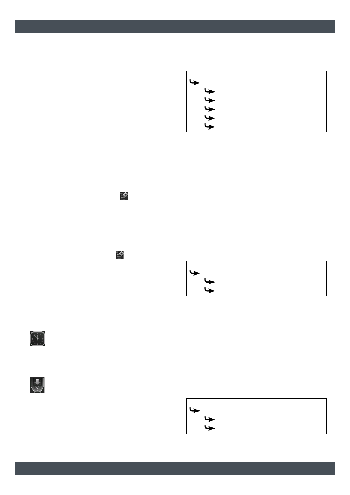
5.2.2 Text menu - Adjustable parameters
Adjustable parameters
Boiler
Ash removal
Start idle time
Duration idle time
De-ash after min.
De-ash after max.
Empty ash box after
Detailed descriptions of the parameters are provided
below.
5.2.2.1 Setting the idle time for boiler deashing
Explanation of [Duration idle time]
The [Duration idle time] parameter is used to select the
duration of the idle time for the boiler's entire de-ashing
system.
The start time for the idle time is set with the [Start idle
time] parameter.
The idle time should be kept as short as possible.
If noise is not expected to be a nuisance, you
should reduce the value to 0 hours.
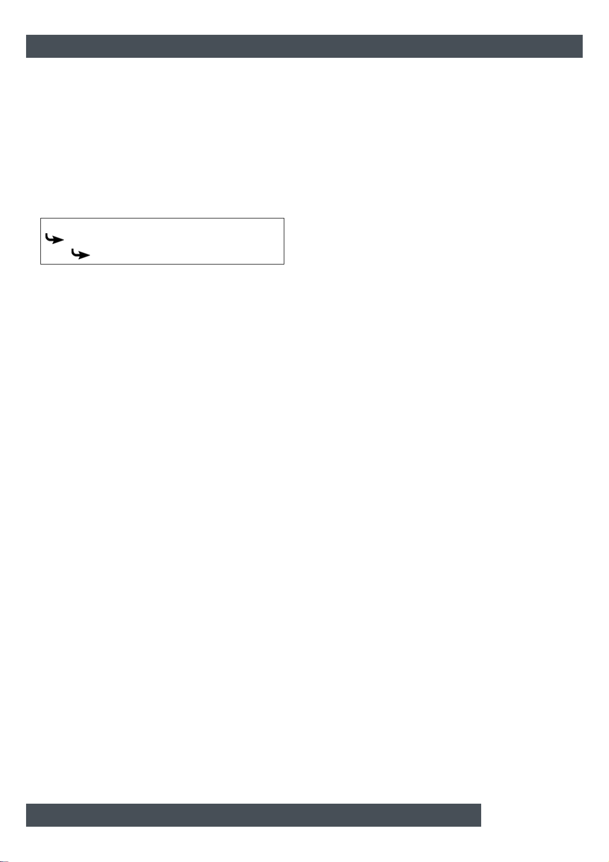
The parameters can be found under:
Boiler
Ash removal
Start idle time
Duration idle time
5.2.2.2 Boiler de-ashing interval
[Fill-up time] button
This sets the daily time for complete refilling of
the boiler pellet bin if pellets have been used.
This prevents refilling during the night. This
time applies for every day of the week.
[Hopper Fill] button
This fills the reservoir on the boiler immediately ,
independent of the suction time settings.
Explanation of [De-ash after min.] and [De-ash
after max.]
The boiler's de-ashing interval is set with the [De-ash
after min.] and [De-ash after max.] parameters. The
boiler de-ashes within the range specified by these two
parameters.
The de-ashing interval may only be modified af ter
consultation with a specialist or ETA customer
service.
The parameters can be found under:
Boiler
Ash removal
De-ash after min.
De-ash after max.
Page 30
[Boiler] function block - PelletsCompact 20-32 kW ETAtouch controller
5.2.2.3 Empty ash box after
Explanation of [Empty ash box after]
This parameter adjusts the quantity of pellets used,
after which a reminder to empty the ash box is
displayed on the screen.
If the ash box is then only partially full, this quantity can
be increased. If you set the value to zero, the reminder
will no longer appear.
The parameter can be found under:
Boiler
Ash removal
Empty ash box after
30 www.eta.co.at
Page 31

ETAtouch controller [Boiler] function block - PelletsCompact 20-32 kW
31
Page 32

[Buffer] function block ETAtouch controller
5.3 [Buffer] function block
Mode of operation
Buffer storage tank overview screen
1 Operating condition and information.
A description of the operating conditions can be
found in the integrated Help menu by pressing the
button.
2 Producer for the buffer.
Currently, the buffer is charged by the burner at a
flow temperature of 72 °C.
3 Temperatures of the buffer for individual areas
(top, middle and bottom)
4 Buffer consumers.
Currently, the consumers are charged with a flow
temperature of 64 °C.
5 [Settings] button.
In this menu, the charge times are set.
In the settings menu ( button), the time window for
buffer charging can be set, and therefore the ch arge
times (see chapter 5.3.1 "
times"). The buffer only requests heat from the boiler
during charge times. Within the charge times, it will
continue to be loaded by the boiler until the required
temperature [Buffer target] has been exceede d in the
upper part of the buffer and the adjustable shutdown
temperature [Buffer bottom off] is reached in the lower
part. The operating mode then changes to [Charged].
If (within the loading times) there is no heat demand
from the consumer, the buffer is charged only to the
adjustable minimum temperature [Buf fer top min.]. The
consumers connected to the buffer (for example,
heating circuit or hot water tank) can also re quest heat
from the buffer outside the charging times. The
charging times of the consumers are independent of
the charging times of the buffer.
Buffer charging times that are too brief can cause
the temperatures in the bu ffer to fall too far and
prevent individual consumers from being supplied with
heat. For this reason, it is advisable to set generous
charging times.
A solar heating system connected to the buffer can
charge it at any time, regardless of the set buffer
charging times.
When the buffer is the only heat producer in the
heating system, the buffer charging times also
indirectly determine the operating hours of the boiler.
Because it can only switch to heating mode within the
buffer charging periods.
Setting the buffer charging
32 www.eta.co.at
Page 33

ETAtouch controller [Buffer] function block
33
5.3.1 Setting the buffer charging times
5.3.2 Buffer with solar heating system
Open the overview of the charging times set
The operating hours of the buffer can be adjusted in
the settings ( button). To adjust, open the settings
and then open the charging times of any given day with
the [Charging times Daily plan] button. An overview
screen opens.
Buffer with solar heating system
The control principles of the solar heating system
and the different variations are described in
chapter 5.7 "
In the overview of the buffer, the solar heating system
appears as another producer for the buffer.
[Solar] function block".
Fig. 5-36: Overview
1 Set time window (charging times)
2 Select day of the week
3 Add another time window
4 Graphical representation of the time window
setting
5 Overview of all time windows for the entire week
6 Delete time window
7 Period of the time window
Setting the time window and copying to other
days of the week is described in chapter 5.1.6.6
"Setting a time window".
Fig. 5-37: Solar heating system on buffer
1 Currently , the buffer is ch arged by the solar heating
system at a flow temperature of 69 °C
2 Additional temperature sensor [Buffer bottom
Solar] for control of the solar heating system
The [Solar priority] function enables the solar
heating system to charge the buffer without the
boiler being started within 2 configurable time slots
(see 5.3.4.9 "
If a stratified charger for the buffer is installed, the sola r
heating system can charge the upper and lower
portion of the buffer. The solar heating system is
Solar priority").
Page 34

[Buffer] function block ETAtouch controller
displayed twice, and the additional buffer temperatures
for solar stratified chargin g are displayed next to the
buffer.
Fig. 5-38: Stratified charging of the buffer
5.3.3 Buffer as a combination tank
Buffer with integrated hot water tank or coils
Fig. 5-39: Combination tank
1 Current hot water temperature
2 [Load immediately] button.
Immediate charging of the hot water, independent
of the set time slots.
In the settings menu ( button), the time window for
the loading of the hot water and the desired hot water
temperature can be set (see chapter 5.3.3.1 "
the hot water charging times").
The configurable [Switch-on diff.] parameter additionally allows you to determine how far the hot water
temperature can drop before the hot water tank ag ain
demands heat from the buffer ( see 5.3.4.12 "
diff.").
[Load immediately] button
This button causes the hot water to be charged
to the highest set temperature of all time slots
and days of the week if the current temperature
has dropped below [Switch-on diff.], ignoring the
current time slot. When active, the button is highlighted
in yellow .
5.3.3.1 Setting the hot water charging times
Opening charging times and temperature for hot
water with a combination tank
The charging times for the hot water an d the set temperatures can be adjusted in the settings ( button).
To adjust, open the settings and then open the
Setting
Switch-on
34 www.eta.co.at
Page 35

ETAtouch controller [Buffer] function block
35
charging times of any given day with the [Hot water
Charging times Daily plan] button. An overview screen
opens.
Fig. 5-40: Overview
1 Set time window (charging times)
2 Select day of the week
3 Add another time window
4 Graphical representation of the time window
setting
5 Overview of all time windows for the entire week
6 Delete time window
7 Adjustable hot water temperature within the time
window
8 Period of the time window
9 Set-back temperature of the hot water outside the
time window
Setting the time window and copying to other
days of the week is described in chapter 5.1.6.6
"Setting a time window".
Page 36

[Buffer] function block ETAtouch controller
5.3.4 Text menu - Adjustable parameters
Adjustable parameters
The following parameters can be configured for the
basic function in the buffer text menu.
Buffer
Buffer top
Buffer top min.
Buffer bottom
Buffer bottom off
Extra charge
Buffer top min.
Buffer bottom off
Extra charging from
Chrg. button
If a solar heating system is additionally connected to
the buffer, further parameters can be set.
Buffer
Solar heat diss.
Activate?
...until buffer max
Buffer top Solar
Buffer top min. solar
Min. out. temp. Solar prio.
Priority
Buffer bottom Solar
Buffer bottom max
Solar priority
a
b
Solar priority
Begin solar prio.
Change priority at
End solar prio.
Min. out. temp. Solar prio.
a. Only visible with several buffer storage tanks and solar
heating system
b. Only visible with solar heating system and buffer with 2
internal coils
c. Only for solar heating systems with switchover between
several tanks
If the buffer is implemented as a combination tank,
further parameters can be set.
Hot water tank
Switch-on diff.
Circulation
Circulation runtime
Circulation pause
Enable circulation
Detailed descriptions of the parameters are provided
below.
5.3.4.1 Buffer top min.
Explanation of [Buffer top min.]
This parameter defines the minimum temperature of
the buffer storage tank inside the configured time slot.
The factory setting for this parameter is 10°C.
The higher this temperature is set, the larger the
heat reserve in the buffer. At the same time, however,
higher temperatures in the buffer reduce the solar
yield. Because the buffer is kept at the [Buffer top min.]
temperature using energy from the boiler, even if there
is no demand from the consumers.
The factory setting can remain unchanged as long as
all components of the heating system are controlled by
the ETA control system. A higher value is required if
peaks in output have to be covered or very fast heat
availability is needed.
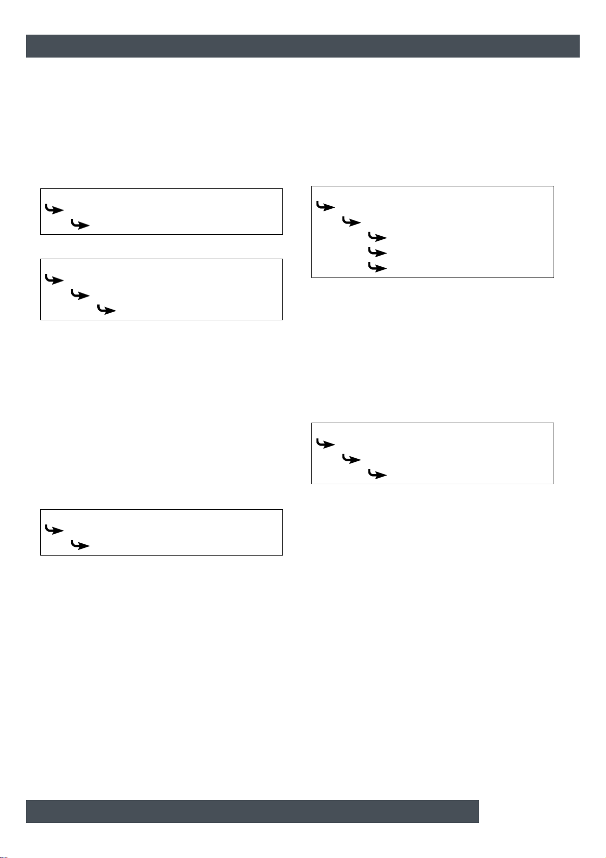
The parameter can be found under:
Buffer
Buffer top
Buffer top min.
Extra solar heat
5.3.4.2 Buffer bottom off
from outside temp.
at buffer top
at buffer bottom sol.
Explanation of [Buffer bottom off]
This parameter ends charging of the buffer storage
tank by the boiler. As soon as the [Buffer bottom]
temperature sensor in the buffer storage tank has
Priority
c
exceeded the configured [Buffer bottom off] temperature, charging of the buffer by the boiler is stopped.
36 www.eta.co.at
Page 37

ETAtouch controller [Buffer] function block
37
The factory setting for this parameter is 40°C.
The value should be at least 5 - 10°C above the
average return temperature of the consumers, but no
more than 70°C.
A high [Buffer bottom off] temperature reduces the
number of boiler starts and improves boiler running
time.
The parameter can be found under:
Buffer
Buffer bottom
Buffer bottom off
5.3.4.3 Function [Extra charge]
Explanation of the [Extra charge] function
This function defines a daily point in time for the buffer
(=[Extra charging from]) to charge the buffer additionally. This charging is done independently of the actual
consumer requirements and independently of the set
time windows.
A separate minimum temperature [B uffer top min .] and
shutdown temperature [Buffer bottom off] can be set
for this charge. Charging ends as soon as the buffer
reaches these temperatures.
The function is deactivated if one of the two tem-
peratures is set to "0".
The parameters can be found under:
Buffer
Extra charge
Extra charge activated?
Buffer top min.
Buffer bottom off
Extra charging from
Chrg. button
At first, set the parameter [Extra charge
activated?] to [Yes], and then the other
parameters will be displayed.
To immediately start this additional buffer charge,
simply set parameter [Chrg. button] to [On].
5.3.4.4 Solar heat diss.
Explanation of the [Solar heat diss.] function
Optional: only for several buffer storage tanks and
solar heating system
This function defines whether the selected buffer may
take up excess solar heat from a buffer charg ed by the
solar heating system.
If you set the function with the [Activate?] parameter
set to [Yes], this buffer takes up the solar excess. This
buffer is then charged up to the configured maximum
temperature [...until buffer max].
The parameter can be found under:
Buffer
Solar heat diss.
Activate?
...until buffer max
5.3.4.5 Priority of the upper and lower
sections
Explanation of [Priority]
Optional: only with solar heating system and buffer
with 2 internal coils
This parameter sets the priority of the top and bottom
sections of the buffer for solar charging. A hig h priori ty
means that this section will be charged by the solar
heating system first. A low priority means that it will be
charged last.
The priority for the top and bottom section of the buf fer
can be found under:
Buffer
Buffer top Solar
Priority
Buffer bottom Solar
Priority
5.3.4.6 Buffer top min. solar
Explanation of [Buffer top min. solar]
Optional: only for solar heating systems with stratified
charging
With stratified charging by the solar heating system,
this sets a minimum temperature for the top section of
the buffer. This way, solar charging only takes place in
the top section once the solar panel is at least 7 °C
warmer than [Buffer top min. solar].
However, this minimum temper ature o nly applies
if the conditions for stratified charging are
satisfied. If they are not, solar charging is switched to
the bottom section of the buffer, to make use of the
solar energy.
The parameter can be found under:
Buffer
Buffer top Solar
Buffer top min. solar
Page 38
[Buffer] function block ETAtouch controller
5.3.4.7 Min. out. temp. Solar prio.
Explanation of [Min. out. temp. Solar prio.]
This parameter sets the minimum value for th e outside
temperature, so that one of the conditions for solar
priority and stratified charging of the buffer storage
tank is satisfied.
The parameter can be found under:
Buffer
Buffer top Solar
Min. out. temp. Solar prio.
or also in:
Buffer
Buffer bottom Solar
Solar priority
Min. out. temp. Solar prio.
5.3.4.8 Buffer bottom max
Explanation of [Buffer bottom max]
Optional: only with solar heating systems
This switch-off temperature can only be set when the
solar heating system is charging the buffer. This configurable temperature sets a threshold for how much
the buffer can be charged by the solar heating system,
in order to prevent the buffer from overheating. If the
[Buffer bottom Solar] temperature sensor reaches the
configured [Buffer bottom max] temper ature, the solar
pump of the solar heating system is switched off.
The parameter can be found under:
Buffer
Buffer bottom Solar
Buffer bottom max
5.3.4.9 Solar priority
Explanation of [Begin solar prio.], [Change priority
at] and [End solar prio.]
Optional: only with solar heating systems
These parameters are used to set the time slots for the
[Solar priority] function.
The first time slot lasts from [Begin solar prio.] to
[Change priority at]. The second time slot begins with
[Change priority at] and ends with [End solar prio.].
Outside the 2 time slots, the boiler can charge the
buffer at any time.
Set the start of solar priority before the first time
window of the heating circuit and hot water tank.
Otherwise, the boiler may start beforeha nd, in or der to
charge the heating circuit or hot water tank.
During the configured times for solar priority, it
may happen that the heating circuits or the hot
water are not supplied with sufficient heat.
The parameters for setting the 2 time windows are in:
Buffer
Buffer bottom Solar
Solar priority
Begin solar prio.
Change priority at
End solar prio.
Set the start of solar priority before the first time
window of the heating circuit and hot water tank.
Otherwise, the boiler may start beforeha nd, in or der to
charge the heating circuit or hot water tank.
During the configured priority times, it may be the
case that the heating circuits or the ho t water ar e
not supplied with sufficient heat.
Switch function on or off
The parameter can be found under:
Buffer
Buffer bottom Solar
Solar priority
Solar priority
5.3.4.10 Extra solar heat
Explanation of [Extra solar heat]
Optional: only with solar heating systems
This function defines whether the buffer storage tank
may convey this excess heat from the solar heating
system to other consumers, even if they do not
currently require any heat.
The following conditions must be met in order for
the excess solar heat to be passed on in this wa y:
• The outside temperature must have exceeded the
configurable value [from outside temp.].
• The [Buffer top] temperature in the buffer must
have exceeded the configurable value of [at buffer
top].
• The [Buffer bottom Solar] temperature in the buffer
must have exceeded the configurable value of [at
buffer bottom sol.].
38 www.eta.co.at
Page 39

ETAtouch controller [Buffer] function block
39
• In the function block for the hot water tank, heating
circuits or other buffer storage tanks, the [Solar
heat diss.] parameter must be set to [Yes], so that
the buffer can request these consumers to t ake on
the excess solar heat.
The parameters [from outside temp.], [at buffer top]
and [at buffer bottom sol.] can be configured in the
buffer text menu.
The [Solar heat diss.] parameter can be configured in
the text menu of the hot water tank or the heating
circuit.
The parameters can be found under:
Buffer
Buffer bottom Solar
Extra solar heat
from outside temp.
at buffer top
at buffer bottom sol.
5.3.4.11 Priority the buffer
Explanation of [Priority]
Optional: only for solar heating systems with
switchover between several tanks
This parameter sets the priority for solar charging of
the buffer. A high priority means that this tank will be
charged by the solar heating system first. A low priority
means that it will be charged last.
The parameter can be found under:
Buffer
Priority
5.3.4.12 Switch-on diff.
5.3.4.13 Circulation runtime
Optional: only for combination tank with circulation
pump
Explanation of [Circulation runtime]
Optional: Only with circulation pump
This parameter sets the duration for operation of the
circulation pump after it has been started. This period
is only valid inside the set time slot.
After the set period has expired, the circulation
pump is switched off for the configurable duration
of the [Circulation pause] parameter.
The parameter can be found under:
Hot water tank
Circulation
Circulation runtime
5.3.4.14 Circulation pause
Optional: only for combination tank with circulation
pump
Explanation of [Circulation pause]
Optional: Only with circulation pump
This parameter sets the period (pause) after a
circulation pump operating phase. The control system
can only restart the circulation pump afte r this time has
elapsed. This pause is only valid inside the set time
slot.
The parameter can be found under:
Hot water tank
Circulation
Circulation pause
Explanation of [Switch-on diff.]
Optional: only with combination tank
With a combination tank, this pa rameter regulates how
far the current warm water temperature can fall before
the hot water tank again demands heat from the boiler .
If the value is set to 15 °C, the current hot water
temperature may drop by 15 °C from the value
[Hot water tank target]. The combination tank do es not
demand heat from the boiler unless this happens.
With a combination tank, this value can be set to
approximately 5°C to 8°C if the amount of hot
water is insufficient.
The parameter can be found under:
Hot water tank
Switch-on diff.
5.3.4.15 Enable circulation
Optional: only for combination tank with circulation
pump
Explanation of [Enable circulation]
Optional: only for circulation pump
This parameter defines the minimum temperature of
the hot water tank for starting th e circulation pump. The
circulation pump only starts once the hot water tank
has exceeded this temperature.
The [Service] access level is required to perform
modifications.
Page 40
[Buffer] function block ETAtouch controller
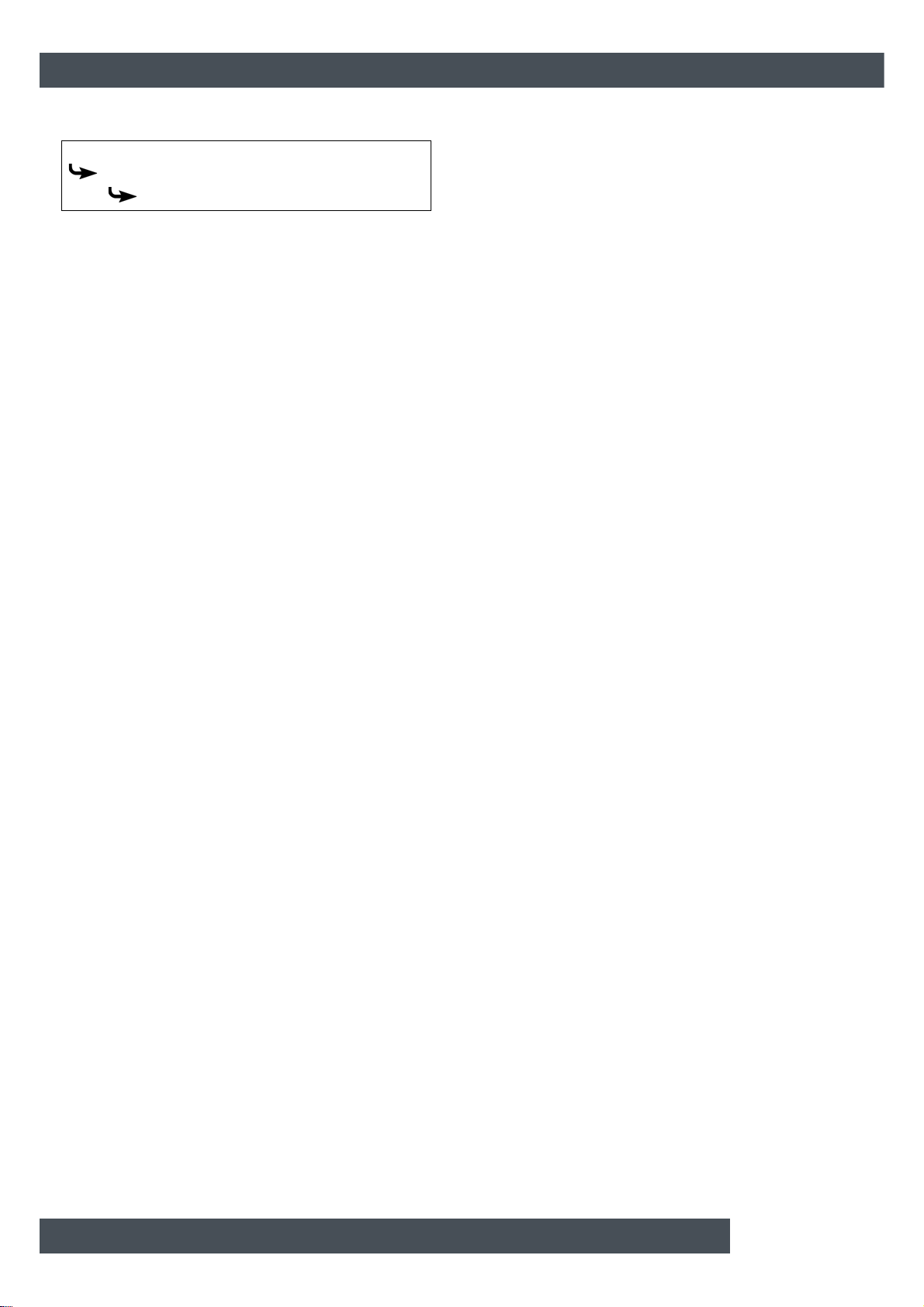
The parameter can be found under:
Hot water tank
Circulation
Enable circulation
40 www.eta.co.at
Page 41

ETAtouch controller [Buffer] function block
41
Page 42

[Hot water tank] function block ETAtouch controller
5.4 [Hot water tank] function block
Hot water tank overview screen
1 Operating condition and information.
A description of the operating conditions can be
found in the integrated Help menu by pressing the
button.
2 Producer for the hot water tank.
Currently, the hot water storage tank is charged by
the buffer with a flow temperature of 61 °C, and
from the solar system with 74 °C.
3 Temperature of the hot water tank.
The temperature in the lower area of the tank only
appears if an additional temperature sensor is
installed.
4 [Load immediately] button.
Immediate charging of the hot water, independent
of the set time slots.
5 [Settings] button.
In this menu, the time window can be set, for
example.
Within the charging times, the hot water is charged to
the set hot water temperature (for example: 60 °C).
The charge starts as soon as the current hot water
temperature is lower than the set hot water
temperature by the adjustable difference [Switch-on
diff.].
Example:
In the time window, the hot water temperature is set to
60 °C. The difference [Switch-on diff.] is 15 °C.
=> Charging starts as soon as the hot water
temperature drops to 45 °C, and it ends as soon as the
hot water has reached 60 °C.
If an additional temperatur e sensor [] is in stalled
for the lower part of the hot water tank, charging
ends as soon as this sensor has reached the configurable temperature [HW bottom off].
[Load immediately] button
This button causes the hot water to be charged
to the highest set temperature of all time slots
and days of the week if the current temperature
has dropped below [Switch-on diff.], ignoring the
current time slot. When active, the button is highlighted
in yellow .
Mode of operation
In the settings menu ( button), the time window for
charging the hot water and the desired hot water
temperature can be set. See chapter 5.4.1 "
hot water charging times".
Setting the
42 www.eta.co.at
Page 43

ETAtouch controller [Hot water tank] function block
43
5.4.1 Setting the hot water charging times
5.4.2 Text menu - Adjustable parameters
Open the overview screen of the set charging
times and temperatures
The charging times for the hot water and the set temperatures can be adjusted in the settings ( button).
To adjust, open the settings and then open the
charging times of any given day with the [Charging
times Daily plan] button. An overview screen opens.
Commonly used parameters can be found in the
settings
Commonly used parameters can be found in the
function block settings ( button). There, the
parameters are identified by the symbol and can be
adjusted by tapping. This saves you having to search
through the text menu for these parameters.
Adjustable parameters
Hot water tank
Switch-on diff.
HW bottom off
Solar heat diss.
Priority
Circulation
c
d
a
b
Circulation runtime
Circulation pause
a. Only visible with additional temperature sensor
b. Only visible for buffers with solar heating system
Fig. 5-41: Overview
1 Set time window (charging times)
2 Select day of the week
3 Add another time window
4 Graphical representation of the time window
setting
5 Overview of all time windows for the entire week
6 Delete time window
7 Adjustable hot water temperature within the time
window
8 Period of the time window
9 Set-back temperature of the hot water outside the
time window
If an additional circulation pump for hot water is
installed, the operating times of this are set in the
same way ( [Circulation times Daily plan] button).
Setting the time window and copying to other
days of the week is described in chapter 5.1.6.6
"Setting a time window".
c. Only visible for solar heating systems with switchover
between several tanks
d. Only visible with additional circulation pump
Detailed descriptions of the parameters are provided
below.
5.4.2.1 Switch-on diff.
Explanation of [Switch-on diff.]
This parameter regulates how far the current warm
water temperature can fall before the hot water tank
again demands heat from the buffer or boiler.
If the value is set to 15 °C, the current hot water
temperature may drop by 15 °C from the value
[Hot water tank target]. The hot water tank only
demands heat from the buffer or boiler when this
happens.
The parameter can be found under:
Hot water tank
Switch-on diff.
5.4.2.2 HW bottom off
Explanation of [HW bottom off]
Optional: only with additional [Hot water tank bottom]
temperature sensor
Page 44
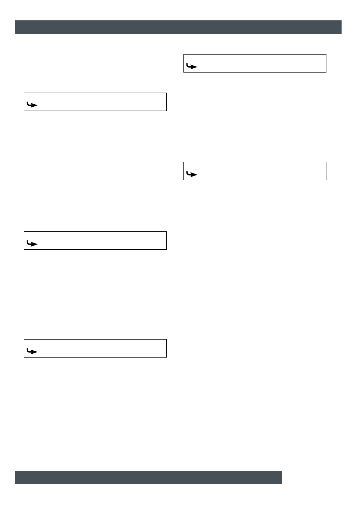
[Hot water tank] function block ETAtouch controller
This parameter defines when charging of the hot wate r
tank will end. As soon as the additional [Hot water tank
bottom] temperature sensor in the hot water tank
reaches the adjustable [HW bottom off] temperature,
charging of the hot water tank ends.
The parameter can be found under:
Hot water tank
HW bottom off
5.4.2.3 Solar heat diss.
Explanation of [Solar heat diss.]
Optional: only for accumulator tanks with solar hea ting
system
This parameter defines whether the hot water tank
may take excess solar heat from the buffer.
If this parameter is set to [Y es], the hot water tank takes
the solar excess up to the maximum temperature [Hot
water tank max.].
This parameter is factory-set to [No]. You must
check the conditions for the [Extra solar heat]
function in the text menu of the accumulator tank.
The parameter can be found under:
Hot water tank
Solar heat diss.
The parameter can be found under:
Circulation
Circulation runtime
5.4.2.6 Circulation pause
Explanation of [Circulation pause]
Optional: Only with circulation pump
This parameter sets the period (pause) after a
circulation pump operating phase. The control system
can only restart the circulation pump af ter this time has
elapsed. This pause is only valid inside the set time
slot.
The parameter can be found under:
Circulation
Circulation pause
5.4.2.4 Priority
Explanation of [Priority]
Optional: only for solar heating systems with
switchover between several tanks
This parameter sets the priority for solar charging of
the hot water tank. A high priority means that this tank
will be charged by the solar heating system first. A low
priority means that it will be charged last.
The parameter can be found under:
Hot water tank
Priority
5.4.2.5 Circulation runtime
Explanation of [Circulation runtime]
Optional: Only with circulation pump
This parameter sets the duration for operation of the
circulation pump after it has been started. This period
is only valid inside the set time slot.
After the set period has expired, the circulation
pump is switched off for the configurable duration
of the [Circulation pause] parameter.
44 www.eta.co.at
Page 45

ETAtouch controller [Hot water tank] function block
45
Page 46

[Fresh water module] function block ETAtouch controller
5.5 [Fresh water module] function block
Fresh water module overview screen
1 Operating condition and information.
A description of the operating conditions can be
found in the integrated Help menu by pressing the
button.
2 Producer for the fresh water module.
Currently , the fresh water module is charged by the
buffer at a flow temperature of 58 °C.
3 Primary side return temperature
4 Circulation pump (only displayed if it has been
installed and is in operation)
5 Hot water temperature (the tap is displayed only
when hot water is currently being drawn)
6 [Settings] button.
In this menu, the time window can be set, for
example.
Function of the fresh water module
The desired hot water temperature is set with the potentiometer on the fresh water module. If [Target value
can be set with rotary knob] has been disabled in the
configuration, different time windows and hot water
temperatures can be set. See chapter 5.5.1 "
the hot water charging times".
Inside these time windows, the upper part of the buff er
is maintained at no lower than the configured ho t water
temperature. Outside the set time windows, the hot
water is maintained at the lowest set temperature of
the time windows, provided that the accumulator tank
is sufficiently hot.
If a circulation pump is installed for the hot wate r,
it will be put into operation as "self-learning" by
default. This means that the hot water taps of the last
2 weeks are stored. The operating times of the current
day will be calculated from this and the circulation
pump is started accordingly.
When this function is switched off, the operating times
for the circulation pump can be set manually. This is
achieved by opening the settings ( button) and
pressing the [Circulation times Daily plan] button.
After commissioning, no more data is available
for the "self-learning" circulation. That is why an
operating period of about 4 weeks is required in the
beginning, so that the control system can save
sufficient data.
Setting
46 www.eta.co.at
Page 47
ETAtouch controller [Fresh water module] function block
47
5.5.1 Setting the hot water charging times
5.5.2 Text menu - Adjustable parameters
Open the overview screen of the set charging
times and temperatures
The standby times for the hot water and the set temperatures can be adjusted in the settings ( button).
T o ad just, open the settings and then open th e standby
times of any given day with the [Stand-by times
Daily plan] button. An overview screen opens.
Fig. 5-42: Overview
1 Set time windows (standby times)
2 Select day of the week
3 Add another time window
4 Graphical representation of the time window
setting
5 Overview of all time windows for the entire week
6 Delete time window
7 Adjustable hot water temperature within the time
window
8 Period of the time window
9 Set-back temperature of the hot water outside the
time window
Setting the time window and copying to other
days of the week is described in chapter 5.1.6.6
"Setting a time window".
If an additional circulation pump is installed, the
operating times of this are set in the same way.
The operating hours can b e acce ssed via th e settin gs
with the [Circulation times Daily plan] button.
Adjustable parameters
Hot water
Automatic venting
Emergency operation only with buffer pump
Circulation
Self-learning
Circulation runtime
Circulation pause
Detailed descriptions of the parameters are provided
below.
5.5.2.1 Function Automatic venting
Explanation of [Automatic venting]
This function attempts to remove introduced air from
the fresh water module automatically.
If the function is activated a nd the controller detect s air
intake, both pumps are operated at full speed for a
short period of time to remove the air from the fresh
water module. This can also take place multiple times
sequentially.
This function is activated by default. During
venting, the hot water can briefly be hotter than
the target temperature set.
The parameter can be found under:
Hot water
Automatic venting
5.5.2.2 Function Emergency operation only
with buffer pump
Explanation of the [Emergency operation only with
buffer pump] function
Emergency operation of the fresh water module can be
activated with this function if the admixing pump is
defective.
If it is activated, water heat ing is only provided by the
buffer pump. Without the admixing pump, calcification
protection of the heat exchangers is not guaranteed
Protracted emergency mode can therefore calcify the
heat exchanger.
The [Service] access level is required to perform
modifications.
The parameter can be found under:
Hot water
Emergency operation only with buffer pump
Page 48
[Fresh water module] function block ETAtouch controller
5.5.2.3 Function Self-learning
Explanation of the [Self-learning] function
With this function, the operating times of the circulation
pump of the last 2 weeks are saved. The operating
times of the current day are calculated based on this
and the circulation pump will be put into operation accordingly.
This function is set to [Yes] at the factory. When
[No] is set, the operating times for the circulation
pump can be set manually.
The parameter can be found under:
Circulation
Self-learning
5.5.2.4 Circulation runtime
Explanation of [Circulation runtime]
Optional: Only with circulation pump
This parameter sets the duration for operation of the
circulation pump after it has been started. This period
is only valid inside the set time slot.
After the set period has expired, the circulation
pump is switched off for the configurable duration
of the [Circulation pause] parameter.
The parameter can be found under:
Circulation
Circulation runtime
5.5.2.5 Circulation pause
Explanation of [Circulation pause]
Optional: Only with circulation pump
This parameter sets the period (pause) after a
circulation pump operating phase. The control system
can only restart the circulation pump after this tim e has
elapsed. This pause is only valid inside the set time
slot.
The parameter can be found under:
Circulation
Circulation pause
48 www.eta.co.at
Page 49

ETAtouch controller [Fresh water module] function block
49
Page 50

[Heating circuit] function block ETAtouch controller
5.6 [Heating circuit] function block
Overview of the heating circuit when a room
sensor is installed
Fig. 5-43: Heating circuit with room sensor
1 Operating condition and information.
A description of the operating conditions can be
found in the integrated Help menu by pressing the
button.
2 Producer for the heating circuit
3 On/Off switch for the heating circuit
= switched on
= switched off
4 Increase or decrease the room temperature
5 [Settings] button.
In this menu, the heating times and the heating
curve can be adjusted, for example.
6 Graphic display of the heating times and roo m tem-
peratures settings
7 Operating mode [Timer]
8 Operating mode [Set-back]
9 Operating mode [Heating]
Overview of the heating circuit without a room
sensor
In the overview, a temperature slider appears, rather
than the measured room temp er ature.
Fig. 5-44: Heating circuit without room sensor
1 Graphic display of the heating times settings
2 Temperature slider
Mode of operation
If the heating circuit is turned on ( ), heat is
supplied on the basis of the time windows set. The
temperature is controlled wit h the heating curve (see
chapter 5.6.3 "
sensor and the time window settings (see chapter
Setting the heating time slots").
5.6.2 "
During a time window, the heating circuit is in heating
mode. If a room sensor is installed, this regulates the
heating circuit so that the set room temperature is
achieved. If a room sensor is not installed, the heating
circuit is controlled with the heating curve for the
heating mode. Accurate temperature control is
therefore difficult.
Outside the set time slots, the heating circuit is in
reduced operation mode. This means that the room
sensor only regulates to the set reduced room
temperature [Set-back temperature outside the time
window]. Without a room sensor, the heating circuit is
controlled with the heating curve for the reduced
operation mode.
Switching between heating and reduced operation
takes place automatically when the button is used
in the user interface to select the [Timer] operating
mode.
The operating modes are also manually adjustable.
Heating mode is activated with the button, and
reduced operation mode with the button. See
chapter 5.6.1 "
The heating curve"), the optional room
Operating elements".
50 www.eta.co.at
Page 51

ETAtouch controller [Heating circuit] function block
51
5.6.1 Operating elements
5.6.2 Setting the heating time slots
[Timer] button
The heating circuit is switched to automatic
mode. This means that changing between
operating modes [Heating] (within a time
window) and [Set-back] (outside a time window) is
based on the set time window. This operating mode is
enabled by default if the heating circuit is turned of f and
then turned back on.
[Heating] button
Thus, the heating circuit is ma nually switched
to heating mode. With the additional switch
(above the symbol), the heating
circuit can be set to remain permanently in heating
mode, thus ignoring any time window, or set
temporarily until the next time window.
[Set-back] button
Thus, the heating circuit is ma nually switched
to reduced operation mode. With the addition al
switch (above the symbol), the
heating circuit can be set to remain permanently in
reduced operation mode, or set temporarily until the
next time window.
Open the overview screen of set heating times
The operating hours of the heating circuit (heating
times) can be adjusted in the s ettings ( button). To
adjust, open the settings and then open the heating
times of any given day with the [Heating times Daily
plan] button. An overview screen opens.
Temperature slider
This slider is only displayed if a room sensor is
installed for the heating circuit. The temperature
slider is used to adjust the desired room
temperature in a range of +/- 5 °C. By sliding the
switch into the blue area of the scale, the flow
temperature is lowered, and thus the room
temperature also. In the red area, the flow temperatur e
is raised.
Adjusting the required room temperature
This field is only displayed if a room sens or
is installed for the heating circuit. The arrows
are used to set the required room temperature. In heating mode, an increase of 1 °C cau ses the
room temperatures of all time slots for all days of the
week to increase by this value.
In reduced operation mode, a reduction by 1 °C
causes the reduced temperature for all days of the
week to decrease correspondingly.
Fig. 5-45: Overview
1 Set time window (heating times)
2 Select day of the week
3 Add another time window
4 Graphical representation of the time window
setting
5 Overview of all time windows for the entire week
6 Delete time window
7 Adjustable room temperature.
This is displayed only when an optional room
sensor is installed.
8 Period of the time window
9 Set-back temperature.
The room temperature may drop to this value
outside the time window.
Setting the time window and copying to other
days of the week is described in chapter 5.1.6.6
"Setting a time window".
Setting absent time (holiday function)
In each heating circuit, a time frame can be defined for
reduced operation mode. The heating circuit is then
operated with the lowest set-back temperature. This
function is also called the holiday function.
Page 52

[Heating circuit] function block ETAtouch controller
To set the holiday function, open the heating circuit
settings ( button), and press the [Vacation]
button. A settings window appears.
Fig. 5-46: Holiday function
1 Start of the period
2 End of the period
5.6.3 The heating curve
Description of the heating curve
The heating curve regulates the flow temperature for
the heating circuit. Each heating circuit has its own
heating curve, as underfloor heating requires different
settings from radiators.
The heating curve is adjusted in the settings of the
heating circuit ( button). Open this and then change
the heating curve in the menu with the [Heat curve]
button. The settings for the heating curve are
displayed.
T ap the da te field to open a calendar to select the date.
Enter the time using the arrow keys. Close the window
using the arrow on the left side.
In the above example, the heating circuit operates in
reduced operation mode from 10 November at 08:00
a.m. until 24 November at 1:00 p.m. After expiry of the
period, the heating circuit independently reverts to
automatic mode.
During the set holiday time period, the heating
circuit is operated only in reduced-temperature
mode. Therefore, you must c heck the set heating limit
for reduced-temperature mode (see chapter 5.6.3.2
"Setting the heating limits"). At settings below 0 °C,
there is a risk of freezing.
Also check the reduced room temperature outside of
the heating times (see 9 "
room temperature may drop to this value outside the
time window."). If the room temperature is set too low,
there is a danger of freezing.
Set-back temperature. The
Fig. 5-47: Heating curve settings
1 Heating curve for heating mode (red line) and
reduced operation mode (blue line)
2 Parameters for setting the heating curve and the
heating limits
3 Change settings for the heating curve in heating
mode or reduced operation mode
The two adjustable parameters [Flow at -10 °C]
and [Flow at +10 °C] are used to define the
heating curve for the heating mode (red line in the
diagram). The resulting line is the heating curve of the
heating mode (within the preset heating times).
The heating curve for reduced operation mode (blue
line in the diagram) is determined by a parallel shift of
the heating curve of the heating mode. This shif t is set
via the [Set-back difference] parameter.
52 www.eta.co.at
Page 53

ETAtouch controller [Heating circuit] function block
53
Based on the current outside temperature, the control
system uses the heating curve to calculate the
required feed temperature for the heating mode. For
example, an outside temperature of -10 °C would
result in a feed temperature of 33 °C (see diagram).
Fig. 5-48: Heating curve of underfloor heating
1 Maximum flow temperature
2 Parameter [Flow at -10 °C] is used for adjusting the
heating curve for outside temperatures below
freezing
3 Parameter [Flow at +10 °C] is used for adjusting
the heating curve for outside temperatures above
freezing
4 Heating threshold for heating mode
5 Heating limit for reduced-tempe rature mode
If an ETA room sensor is installed for the heating
circuit, the flow temperature calculated on the
basis of the heating curve is corrected. The actual flow
temperature will then differ from the calculated
temperature value.
For each heating circuit, separate heating limits are
adjustable for heating mode (within the set heating
times) and reduced operation mode (outside the set
heating times). If the current outside temperature
exceeds the configured heating temperature (for
example 18 °C), the heating circuit is switched of f. The
same applies to reduced-temperatur e mode as soon
as the outdoor temperature exceeds the set heating
limit.
The [Flow max] parameter determines the
maximum flow temperature for the heating circuit,
to protect it from overheating. The factory setting is 45
°C for underfloor heating, and 65 °C for radiators.
When should the heating curve be adjusted?
If the rooms are not warming up, you should check the
following points first before changing the heating curve
in the control system. Cold rooms are often not only
caused by an incorrectly set graph.
Rooms with radiator thermostats or room
thermostats
• Check the current setting of the radiator thermost at
or the room thermostat. If a room is n ot warm, open
the thermostat fully or increase the temperature
setting on the thermostat.
Fig. 5-49: Radiator thermostat and roomthermostat
If the room is still not warm in heating mode (within
the preset heating times), the temperature slider in
the control system must be set higher (see chapter
Operating elements") or the heating curve
5.6.1 "
needs to be adjusted (see 5.6.1 "
elements").
If the room is too warm in heating mode,
leave the radiator thermostat and room
controller open, and instead lower the temperature
slide in the control system or the heating curve.
If the rooms are too warm or cold in reduced
operation mode (outside the heating times), only
the [Set-back difference] parameter needs to be
adjusted. See chapter Fig. 5-53: "
operation mode".
• Check the adjusted heating limits in the control
system, see chapter 5.6.3.2 "
limits". Heating limits that are set too high or too
low can be the reason for rooms being too cold or
too warm.
Setting the heating
Operating
Adjust reduced
Page 54

[Heating circuit] function block ETAtouch controller
Check operating mode and target room
temperature on the ETA room sensor
• If a room is too cold, check the room sensor, or in
the control system set the operating mode and the
desired room temperature. It is possible that the
heating circuit has been switched off or the room
temperature is set too low.
Fig. 5-50: ETA room sensor
• Check the settings of the following parameters in
the text menu of the heating circuits:
–[Room effect], see chapter 5.6.4.1 "
effect"
–[Switch-on diff. room] and [Switch-off diff.
room] see chapter 5.6.4.2 "
room and Switch-off diff. room"
• If during heating mode the rooms are constantly
too cold (within the set heating times), the heating
curve must be adjusted. See chapter Fig. 5-51:
"Adjust heating curve (at outdoor temperatures
above freezing)".
If the rooms are too cold in reduced-temperature
mode (outside the heating times), only the [Setback difference] parameter needs to be adjusted .
See chapter Fig. 5-53: "
mode".
Check the heating time settings
• Check the heating time settings in the control
system, see chapter 5.6.2 "
slots".
For heating systems with buffer storage, often
heating times that are too short are the reason for
insufficiently warm rooms. Short heating times
(less than 5 hours continuous heating) are p articularly ill-advised for underfloor heating because
such systems react very slowly.
Optimal operation is enabled with low feed temperatures (=[Flow at +10 °C] and [Flow at -1 0 °C])
for the heating curve and long continuous heating
times (10-14 hours). Thus, the he at is transferred
evenly throughout the room. Therefore, it is
advisable (in heating systems with a buffer) to first
set a longer heating time and wait a few days. If the
rooms are then still too cold, the heating curve
must be adjusted. See chapter 5.6.1 "
elements".
Adjust reduced operation
Setting the heating time
Switch-on diff.
Room
Operating
If no buffer storage tank is available,
several short heating times must be set with
pauses in between. This increases the heat
absorbed by the heating circuit from the boiler in
the short heating times. Through this heating time
interruption, the screed becomes a "buffer" in case
of underfloor heating. Between the heating times,
the screed cools and then absorbs heat again. In a
well-insulated building, observe the following
guidelines:
–Radiator heating: several intervals with
3 hours of heating and 2 hours break
–Underfloor heating: several intervals with
4 hours of heating and 3 hours break
The optimum settings depend on the heat de mand
of the building and each room. Explore this in consultation with your heating contractor or ETA
customer service.
54 www.eta.co.at
Page 55

ETAtouch controller [Heating circuit] function block
55
5.6.3.1 Adjusting the heating curve
Adjusting the heating curve
The heating curve is adjusted through the settings of
the heating circuit ( button) in the heating curve
menu ( button). How the heating curve is altered
depends on whether the rooms are always too warm or
too cold at outdoor temperatures above freezing or
below freezing.
Make adjustments to the heating curve in small
increments only. For underfloor heating, never
change more than 2 °C at once, and for radiators never
more than 4 °C. You may need to adapt the heating
curve again after a couple of days, but if you, do it in
small increments, it is more precise and energy
efficient.
At outdoor temperatures below freezing, the
rooms are always too hot or too cold:
1. Only parameter [Flow at -10 °C] is adjusted.
2. Change the selector switch to the heating mode
position ( ). Use the arrow keys to
reduce parameter [Flow at -10 °C] if it is too warm,
or increase if it is too cold.
At outdoor temperatures above freezing, the
rooms are always too hot or too cold:
1. Only parameter [Flow at +10 °C] is adjusted.
2. Change the selector switch to the heating mode
position ( ). Use the arrow keys to
reduce parameter [Flow at +10 °C] if it is too warm,
or increase if it is too cold.
Fig. 5-51: Adjust heating curve (at outdoor temperatures
above freezing)
Fig. 5-52: Adjust heating curve (at outdoor temperatures
below freezing)
Outside the heating times , the rooms are always
too hot or too cold:
1. Then only the reduction is adjusted with parameter
[Set-back difference].
2. Change the selector switch to the reduced
operation mode position ( ). Use the
arrow keys to reduce parameter [Set-back
difference] if it is too cold, or increase if it is too
warm.
Fig. 5-53: Adjust reduced operation mode
With underfloor heating, reduced operation mode is
only partially noticeable because this heating system
reacts very slowly due to the high thermal mass of the
screed. Changes in parameters [Set-back difference]
are therefore often not noticeable.
Page 56

[Heating circuit] function block ETAtouch controller
5.6.3.2 Setting the heating limits
Specifying the heating limits for the heat ing circuit
For each heating circuit, separate heating limits are
adjustable for heating mode (within the set heating
times) and reduced operation mode (outside the set
heating times).
If the current outside temperature exceeds the
configured heating tem perature (for example 18 °C),
the heating circuit is switched off. The same applies to
reduced-temperature mode as soon as the outdoor
temperature exceeds the set heating limit.
If the outside temperature falls below the set
heating limit (for example: 18 °C), a hysteresis of
2 °C will be observed in order to avoid cycling the
heating circuit. Accordingly, the heating circuit will
switch on only once the outside temperature falls
below 16 °C (=18 °C - 2 °C).
The heating limits are adjusted through the settings of
the heating circuit ( button) in the heating curve
menu ( button).
Setting heating limits for heating mode
1. Change the selector switch to the heating mode
position ( ).
Use the arrow keys to reduce parameter [Heating
threshold], so that the heating circuit in heating
mode switches off at a lower outside temperature,
or increase the value.
Setting heating limits for the reduced operation
mode
1. Change the selector switch to the reduced
operation mode position ( ).
Use the arrow keys to reduce parameter [Heating
threshold], so that the heating circuit in reduced
operation mode switches off at a lower outside
temperature, or increase the value.
At settings below 0 °C, there is a risk of
freezing.
Fig. 5-55: Heating limit for reduced-temperature mode
Fig. 5-54: Heating threshold for heating mode
56 www.eta.co.at
Page 57
ETAtouch controller [Heating circuit] function block
57
5.6.4 Text menu - Adjustable parameters
5.6.4.1 Room effect
Explanation of [Room effect]
Optional: only for room sensor
The flow temperature is calcul ated on th e basis o f the
heating curve and the outside temper ature. If the room
temperature falls by 1°C, the target flow temperature is
increased by this set value. If the room temperature
rises by 1°C, the target flow temperature is decreased
by the set value.
For underfloor and wall heating with a design
temperature of 30 °C, set the room influence to 1
°C; with a design temperature of 40 °C, set it to 2 °C.
The [Service] access level is required to perform
modifications.
The parameter can be found under:
Heating circuit
Room
Room effect
5.6.4.2 Switch-on diff. room and Switch-off
diff. room
Explanation of [Switch-on diff. room] and [Switchoff diff. room]
Optional: only for room sensor
These parameters specify the allowed deviation o f the
set room temperature for switching the heating circuit
on and off.
Example:
Room temperature setting = 21 °C
[Switch-on diff. room] = 0.5 °C
[Switch-off diff. room] = 2 °C
=> The heating circuit will be switched off as soon as
the room temperature reaches 23 °C (=21 + 2 °C). If
the room temperature falls to 21.5 °C (=21+0.5 °C),
heat is supplied to the heating circuit again.
The [Service] access level is required to perform
modifications.
The parameter can be found under:
Heating circuit
Room
Switch-on diff. room
Switch-off diff. room
Page 58

[Solar] function block ETAtouch controller
5.7 [Solar] function block
Overview of the solar heating system
1 Operating condition and information.
A description of the operating conditions can be
found in the integrated Help menu by pressing the
button.
2 Collector temperature
3 Solar heating system consumer.
Currently , the hot water storage tank is loaded from
the solar heating system with a flow temperature of
74 °C. The second buffer consumer is not currently
charged.
The solar heating system control principle
The ETA control principle for solar heating systems is
defined so that an adjustable temperature difference
between the panel and the tank (or the upper and
lower buffer area in a buffer with 2 internal coils) is
complied with. This is done by adjusting the speed of
the solar pump.
Manual switching between "High Flow" (high sp eed a t
a lower collector temperature) and "Low Flow" (low
speed at a higher collector temperature) is not
necessary, because this is automatically controlled.
The ETAtouch control system is compatible with a
great many versions, for enabling the integration of a
solar heating system. The various versions are
described below.
5.7.1 Solar heating system with one tank
Solar heating system with only one tank
The solar heating system is controlled by switching the
collector pump on and off. This is switched on as soon
as the collector has exceeded the minimum
temperature [Collector min] and is warmer by the
difference [Switch-on diff.] (factory setting 7 °C) than
the tank being charged.
Fig. 5-56: Solar heating system connected to buffer
The speed of the collector pump is controlled in
such a way that the collector supplies a
temperature that is higher than the current tank
temperature by the configurable offse t [Target collector
diff.].
When the tank has reached its maximum temperature
(the factory setting of the buffer is 90 °C, and the hot
water tank 60 °C), or if the collector is only warmer by
the offset [Switch-off diff.] (factory setting 5 °C) than
the tank, the collector pump is switched off.
Example:
Buffer temperature [Buffer bottom Solar]: 45 °C
[Target collector diff.]: 10 °C
[Switch-off diff.]: 5 °C
=> The speed of the solar pump is adju sted, so that the
temperature on the collector reaches 55 °C. With the
increase in buffer temperature, the collector
temperature also increases, because the 10°
difference is adhered to.
If the collector temperature cannot be increased
(because the sun provides too little heat), the collector
pump switches off when there is only a 5 °C difference
between the collector and the buffer. Otherwise, the
buffer is charged to the maximum temperature of 90
°C.
58 www.eta.co.at
Page 59
ETAtouch controller [Solar] function block
59
5.7.2 Solar heating system with 2 tanks
Switching between several tanks
If the solar heating system charges several tanks (for
example, buffer and hot water tanks) it will switch
between tanks on the basis of the currently set
priorities. The tank with the highest priority is charged
first.
Fig. 5-57: Solar heating system for the buffer and hot water
tank
If the solar power is not sufficient for cha rgi ng the tank
with the highest priority (collector is only warmer b y the
difference [Switch-off diff.] than the tank that currently
requires charging), the tank with the next highest
priority is charged after the min imum time ha s elap sed
(factory setting 20 minutes).
If the solar power increases once more, after the
minimum time has elapsed solar charging switches
back to the tank with the higher priority. This ensures
that the tank with the highest priority is always char ged
first.
Uniform charging of tanks without consid eration
of individual priorities is also possible. The
[Service] permission is required for this. Then you can
use the [Changeover if diff. >] parameter in the solar
heating system text menu to configure the temperature
difference between the tanks.
5.7.3 Solar heating system for buffer with 2 internal coils
Switching between two internal coils
When switching between two internal coils, charging is
defined in two different areas of the buffer. The
purpose is to produce a sufficiently high temperature in
the top part of the buffer, so that the boiler does not
have to start for hot water charging.
Fig. 5-58: Solar heating system with switching between two
coils at the buffer
The solar pump starts as soon as the panel is warmer
than the current temperature in the upper buffer area
[Buffer top Solar].
An internal target temperature [Buffer target solar] is
provided to control switching. The target temperature
is determined by referencing cur rent requirements or
minimum temperatures and can be viewed in the
buffer's text menu under:
Buffer
Buffer top Solar
Buffer target solar
The conditions for solar ch arg ing in to t he up per buffer
coil are:
• The buffer is not currently charged from the boiler.
• The outside temperature is above the set minimum
temperature of 10 °C ([Min. out. temp. Solar prio.],
see chapter 5.3.4.7 "
• The temperature in the upper buffer area [Buffer
top Solar] is lower than the target temperature
[Buffer target solar]
If all conditions are met and the collector is sufficiently
warm, the upper buffer area will be charged until the
target temperature [Buffer target solar] is exceeded.
Subsequently, solar charging is switched to the lower
coil in order to charge this buffer area.
Min. out. temp. Solar prio.")
Page 60

[Solar] function block ETAtouch controller
If one of the described conditions is not met (for
example, if the buffer is currently being charged
by the boiler), there is no reason to feed the solar
charge to the upper buffer coil. Therefore, the solar
charge is directed into the lower coil in order to charge
this area. If all conditions are once ag ain met, charging
is switched to the upper coil.
The only exception to this is when solar power
increases while charging the lower buffer coil.
Then, once the minimum time (factory setting 20 min.)
passes, charging will switch to the upper coil, although
the conditions are not met.
5.7.4 Solar heating system with external heat exchanger
Solar heating system with external heat exch anger
The control principle is the same as in a solar heat ing
system with just one tank, see chapter 5.7.1 "
heating system with one tank".
The speed of the collector pump also controls the
adjustable temperature difference [Target collector
diff.] between the collector and the tank.
Solar
Fig. 5-59: Solar heating system with external heat exchanger
connected to buffer
In addition, a variable speed secondary pump is
available for the heat exchan ger. Through speed
adjustment, it attempts to adapt the temperature
difference between collector and sec ondary flow (see
chart 78 °C - 74°C = 4 °C) to the temperature
difference between the return of the solar heating
system and the tank (49 °C - 45 °C = 4 °C).
Fig. 5-60: Regulation principle
60 www.eta.co.at
Page 61

ETAtouch controller [Solar] function block
61
In solar heating systems with external heat
exchangers, experience has shown that most of the
energy from the solar heating system goes to the tank
in this control principle.
5.7.5 Solar heating system with external heat exchanger and stratified charging valve
Solar heating system with external heat exch anger
and stratified charging valve
This variation of solar heating system also aims to
produce a sufficiently high temperature in the upper
area of the buffer, so the boiler does not have to start
for hot water charging.
Fig. 5-61: Solar heating system with external heat exchanger
and stratified charging valve
The collector pump starts as soon as the collector is
warmer than the target temp erature in the upp er buf fer
area [Buffer target solar].
The control principle is identical to that of a buffer with
two internal coils. The conditions for solar charging into
the upper buffer coil are also the same. They are
described in chapter 5.7.3 "
buffer with 2 internal coils".
The speed control of the secondary pump is identical
to that of a solar heating system with an external heat
exchanger, see chapter Fig. 5-60: "
principle".
The only difference is the switching of solar
charging from the lower buff er coil to the u pper. If
the conditions for solar charging into the uppe r coil are
not met, the lower coil will be charged first. If the
secondary feed temperature rises enough that the
temperature in the upper buffer area [Buffer top Solar]
is exceeded, solar charging is immediately switched to
the upper coil. There is no minimum time for solar
charging. Once the secondary feed temperature drops
below the temperature [Buffer top Solar], the lower coil
is again charged.
The secondary flow temperature rises when the
collector temperature increases or the speed of
the secondary pump decreases.
Solar heating system for
Regulation
Page 62

[Solar] function block ETAtouch controller
5.7.6 Text menu - Adjustable parameters
5.7.6.1 Collector min
Explanation of [Collector min]
This parameter sets the minimum temperature for
starting the solar pump. The solar pump can only be
started once the solar panel has exceeded this temperature.
Do not set this temperature too high, to ensure
that it is possible for heat to supplied to pre-he at
the tank even when there is little sunlight. The optimal
range is between 30 °C and 50 °C.
The parameter can be found under:
State
Collector
Collector min
5.7.6.2 Target collector diff.
Explanation of [Target collector diff.]
This parameter sets the desired temperature
difference between the solar panel and the connected
tank (buffer or hot water tank). This temperature
difference is controlled by adjusting the speed of the
solar pump.
If the buffer is being charged by th e solar heating
system, the temperature of the solar panel
[Collector] is compared with the buffer temperature
[Buffer bottom Solar]. If the hot water tank is being
charged, the [Hot water tank bottom] temperature is
compared.
A high temperature difference results in a low
speed of the solar pump. This way, a smaller
quantity of water is conveyed through the solar panel.
The water remains in the solar panel for a longer time,
and therefore produces a higher working temperature
in the panel. Consequently, a higher hot water
temperature is achieved, but there are also more
losses from the solar panel.
A low temperature difference results in a high
speed of the solar pump. A larger quantity of
water is therefore conveyed through the solar panel.
The water remains in the solar panel for a short time,
and so also becomes less hot. The working
temperature of the solar panel is therefore lower, but
there are fewer losses via the solar panel.
The parameter can be found under:
State
Collector pump
Target collector diff.
62 www.eta.co.at
Page 63

ETAtouch controller [Solar] function block
63
Page 64

[External heat source] function block ETAtouch controller
5.8 [External heat source] function
block
Overview of external heat sources (additio nal heat
producer)
1 Operating condition and information.
A description of the operating conditions can be
found in the integrated Help menu by pressing the
button.
2 Temperature of the ETA boiler
3 Temperature of external heat source
4 External heat source consumer.
Currently , the consumer is char ged by the external
heating at a flow temperature of 54 °C.
boiler, which then supplies heat. If this temperature
is exceeded, the valve switches to the external
heat source.
• External heat source with charging pump:
The external heat source features a separate
pump and can simultaneously convey heat to the
buffer together with the boiler.
The charging pump starts up when the external
heat source has exceeded the minimum
temperature [Enable temperature]. In addition, the
temperature of the external heat source must be
higher than the temperature of the charging tank,
plus the difference [Thermostat diff.]. These
parameters are configurable, see chapter 5.8.1.3
"Enable temperature" and 5.8.1.4 "Thermostat
diff."
If the external heat source exceeds the configurable [Switch off boiler at] temperature, the ETA
boiler is switched to [Locked] mode, see chapter
5.8.1.1 "
Switch off boiler at".
How the external heat source works
"External heat source" refers to an additional nonautomatic heat producer in the heating system. This is
often a fireplace or wood chip boiler which cannot be
requested by the ETAtouch control system, but not an
oil or gas burner.
This can work in several ways, depending on how the
additional heat producer was installed:
• External heat source with diverter valve:
The boiler or the external heat source supplies
heat to the consumers. Switching between the ET A
boiler and the external heat source is achieved via
a diverter valve.
With the configurable parameter [Enable diverter
valve], you can set the minimum temperature for
switchover between the ETA boiler and the
external heat source. See chap ter 5.8.1.2 "
diverter valve".
If the temperature of the external heat source is
below this minimum temperature [Enable diverter
valve], the diverter valve switches to the ETA
Enable
64 www.eta.co.at
Page 65
ETAtouch controller [External heat source] function block
65
5.8.1 Text menu - Adjustable parameters
Adjustable parameters
Ext. heat
Switch off boiler at
Enable diverter valve
This parameter sets the minimum temperature of the
external heat source, for st arting the chargin g pump of
the external heat source.
The parameter can be found under:
Charging pump
Enable temperature
Charging pump
Enable temperature
Thermostat diff.
Detailed descriptions of the parameters are provided
below.
5.8.1.1 Switch off boiler at
Explanation of [Switch off boiler at]
This parameter determines at what temperature of the
external heat source the ETA boiler switches to
[Locked] mode.
If the temperature of the external heat source lies
below this temperature [Switch off boiler at], the ETA
boiler always supplies the heat. If this temperature is
exceeded, the ETA boiler switches to [Locked] mode.
The parameter can be found under:
Ext. heat
Switch off boiler at
5.8.1.2 Enable diverter valve
5.8.1.4 Thermostat diff.
Explanation of [Thermostat diff.]
Optional: only with charging pump
This parameter is used to set the minimum difference
between the temperature of the extern al heat source
[Ext. heat] and the tank that needs charging [Tank temperature], to start the charging pump of the external
heat source.
The parameter can be found under:
Charging pump
Thermostat diff.
Explanation of [Enable diverter valve]
Optional: Only with diverter valve
This parameter is used to set the minimum
temperature for the switchover between the ETA boiler
and the external heat source.
If the temperature of the external heat source is below
this minimum temperature, the diverter valve switches
to the ETA boiler, which then supplies the heat. If this
temperature is exceeded, the valve switches to the
external heat source, which supplies the heat.
The parameter can be found under:
Ext. heat
Enable diverter valve
5.8.1.3 Enable temperature
Explanation of [Enable temperature]
Optional: only with charging pump
Page 66

[Pellet store] function block ETAtouch controller
5.9 [Pellet store] function block
Pellet store overview screen
1 Operating condition and information.
A description of the operating conditions can be
found in the integrated Help menu by pressing the
button.
2 Current pellet stock.
This is calculated by the control system and can
therefore differ by +/- 15% from the a ctual pellet
supply
3 Consumer of the pellet store (boiler)
4 Enter new stock levels after filling
[Stock level] button
After filling the pellet store, a new supply of
pellets is fed in with this button.
Example: 1200 kg of pellets are available, and
3000 kg is refilled. The new stock will be registered as
4200 kg.
Entering a minimum level for the pellet stock
You can define a minimum level for the pellet stock so
that a warning is issued when the stock goes below
that level.
The minimum level is set with the [Warning limit for
pellet stock] parameter in the text menu of the pellet
stock.
66 www.eta.co.at
Page 67

ETAtouch controller [Pellet store] function block
67
Page 68

[Pellet store with switch unit] function block ETAtouch controller
5.10 [Pellet store with switch unit]
function block
Overview of pellet store with switching unit
Up to 4 suction heads can be controlled by one
switching unit.
1 Operating condition and information.
A description of the operating conditions can be
found in the integrated Help menu by pressing the
button.
2 Current pellet stock.
This is calculated by the control system and can
therefore differ by +/- 15% from the a ctual pellet
supply
3 Manually switch to next enabled suction probe
4 Enter new stock levels after filling
5 Suction probe enabled: pellets can be conveyed
from this suction probe.
6 Suction probe restricted: this suction probe is not
activated by the switching unit
Disabling and enabling a suction probe
This symbol represents an enabled suction
probe. This can be controlled by the switching
unit for conveying the pellets. If an enabled
suction probe is selected, then this is locked (
symbol). It will then no longer be activated by the
switching unit. By re-selecting the locked suction
probe, it is enabled again ( symbol).
Function of the switching unit
The conveying and clear modes are represented by a
green line between an enabled suction head and the
switch unit. If a suction head is no longer able to
convey pellets, the control system automatically
switches to clear mode. Here, the conveying hose now
introduces back air , in order to dislodg e any blockages
in the conveying hose or suction head.
If an enabled suction probe is selected ( symbol),
this is then locked ( symbol). It will then no longer be
activated by the switching unit. Re-selection of the
locked suction probe frees it again ( symbol).
The switch unit regularly switches between the
individual, enabled suction heads, to ensure that the
pellet store is emptied uniformly. You can adjust the
maximum number of fill-up operations by a suction
head, see 5.10.1.1 "
With the button, you can also manually ch ange
to another enabled suction probe.
Entering a minimum level for the pellet stock
You can define a minimum level for the pellet stock so
that a warning is issued when the stock goes below
that level.
The minimum level is set with the [Warning limit for
pellet stock] parameter in the text menu of the pellet
stock.
Switching at".
5.10.1 Text menu - Adjustable parameters
5.10.1.1 Switching at
[Stock level] button
After filling the pellet store, a new supply of
pellets is fed in with this button.
Example: 1200 kg of pellets are available, and
3000 kg is refilled. The new stock will be registered as
4200 kg.
Manually changing suction probes
This button manually switches to the next
enabled suction probe, in order to move the
pellets.
Explanation of [Switching at]
This parameter sets the maximum number of suction
operations of an enabled suction head. When a
suction head has reached this number, the switch unit
automatically changes to the next enabled suction
head.
The parameter can be found under:
Conveying system
Switching at
68 www.eta.co.at
Page 69
Emission measurement
69
6 Emission measurement
Why measure emissions?
It is a requirement for the carbon monoxide (CO)
emissions of every boiler to be measured periodically.
In Germany, this periodic measurement must also
include a dust measurement.
There are several aspects of this that could go wrong,
resulting in incorrect measurements even though the
boiler fully and consistently complies with these limits
when operating in accordance with the relevant
standards.
Notes on emission measurement in Germany
In accordance with the provisions of "BImSchV,"
lower limit values for the emission measurement
in Germany apply to all new heating system installations starting 1 January 2015. Notes on compliance
are found under 7 "
Clean the boiler 3 - 5 days before the emission
measurement
Thoroughly clean the boiler and flue pipe 3 - 5 days
before the emission measurement. Once this is
complete, heating can resume as usual.
This delay between cleaning and measurement
is necessary in order to allow dust disturbed
during cleaning to settle again. If the chimney sweep
measures unsettled dust, the dust reading will be
higher than normal and thus inaccurate.
Low-emission operation".
If [Combination] is selected, first the measure-
ments for full load are performed. After expiry of
the selected duration ([MeasDuration]), a message will
appear that states that the measurement for the partial
load can now be performed.
Setting the duration of the emission measurement
The duration of the emission measurement is
factory-set to 45 minutes. If necessary, this can
be increased with the [Service] access level. To do so,
switch to the text menu of the boiler . Y ou can adjust the
duration as follows:
Boiler
Flue gas
Emission measure
MeasDuration
Prepare and perform emissions measurement
1. The boiler must be switched on with the On/Off
switch. In the boiler overview, press the
[Measurement] button in order to open the
emissions measurement settings window.
CAUTION!
Under no circumstances clean the bo iler and flue
pipe on the day of the measurement!
Ensure sufficient heat consumption
Open all radiator valves and turn radiator thermostats
to maximum.
Selecting emission measurement for full load or
partial load
National regulations may stipulate emission
measurement at partial load. If this is the case, you
must set the required output range before
commencing the emission measurement.
With access level [Service] go to the text menu of the
boiler. You can adjust the output range as follows:
Boiler
Flue gas
Emission measure
Measurement type
Fig. 6-1: Settings window for emission measurement
2. Use the [Begin measurement] button to enter
the date agreed for chimney sweeping. The boiler
will then start in time to reach the permissible
operating temperature for measurement purposes.
By pressing the [Start now] button, the boiler
will immediately begin preparations for a
subsequent measurement.
In addition, the locking time of the boiler can be
adjusted ( [Lock duration] button). This relates
to the set time of the measurement. During this
period no heating operation will be started, so that
the heating system has time to cool down.
Page 70

Example: If a time of 17:00 is set for the emission
measurement and at [Lock duration] 8 h, heating
will end at 09:00 .
3. If the date has been entered, it will appear in the
boiler overview. The boiler will then start in time to
reach the permissible operating temperature for
measurement purposes.
Fig. 6-2: Set date
4. If the boiler is ready for emissions measurement, a
corresponding message will appear on the screen.
In addition, a countdown for the emissions
measurement will be displayed. The emission
measurement is to be carried out during this
period.
Emission measurement
Fig. 6-3: Countdow n
5. Switch the boiler back to normal mode after the
emission measurement. To do this, press the
[Deactivate measurement] button in the
settings window. If you do not press this button, the
boiler will automatically switch back to normal
mode after some time.
70 www.eta.co.at
Page 71

Low-emission operation
71
7 Low-emission operation
Notes on complying with limit values in Germany
after 1 January 2015
In accordance with the provisions of "BImSchV," lower
limit values for the emission measurement in Germany
apply to all new heating system installations starting
1 January 2015. In particular, compliance with the new
dust limit value of 20 mg/m³ can lead to problems in
practice.
It was determined under laboratory conditions in
testing centres that the ETA boiler complies with the
new limit values. T o be fair , howe ver, it sho uld be noted
that high-quality fuels were used and the heating
system operated under optimal conditions. Things look
different in practice. Low-quality fuels are often used,
which represents a problem for the dust limit value.
Fuels used for testing
The following fuels were used as test fuel for emission
measurements and approval of the boiler:
• Pellets according to EN ISO 17225-2 with the
designation "D06 M10 A0.5"
The ash content of the fuel is an indicator for the
dust emission
According to the current state of science, dust
emissions from complete combustion are inorganic
components in the fuel, so-called aerosol formers.
Studies by renowned research institutes have clearly
demonstrated that the aero sol formers present in the
fuel (e.g., potassium, calcium, sulphur, chlorine,
sodium, zinc, silicon, phosphorous...) are released in
relatively fixed proportions. Accordingly, the level of
dust emissions is determined by the proportions of
these aerosol formers in the fuel.
The situation is made difficult by the fact that the
percentage of aerosol formers in the wood depends on
many factors (tree species, soil condition, season…).
Even different parts of the tree (trunk, branches, core/
sapwood) can demonstrate stark fluctuations.
In practice, the ash content of the fuel has proven to be
a good indicator of the percentage of aerosolformers.
In order to operate the system with the lowest possible
dust emissions, a properly maintained condition as
well as high-quality fuels with the lowest possible ash
content (barks, impurities, leaves, needles...) are indispensable.
a chimney of a building, from a furnace or from any
fixed boiler if located in a designated smoke control
area. It is also an offence to acquire an "unauthorised
fuel" for use within a smoke control area unless it is
used in an "exempt" appliance ("exempted" from the
controls which generally apply in the smoke control
area).
In England appliances are exempted by publication o n
a list by the Secretary of State in accordance with
changes made to sections 20 and 21 of the Clean Air
Act 1993 by section 15 of the Deregulation Act 2015.
Similarly in Scotland appliances are exempted by
publication on a list by Scottish Ministers under section
50 of the Regulatory Reform (Scotland) Act 2014.
In Wales and Northern Irel and these are auth orised by
regulations made by Welsh Ministers and by the
Department of the Environment respectively.
The ETA PC 20, 25 and 32 kW boiler has been
recommended as suitable for use in smoke control
areas when burning wood pellets according to EN ISO
17225-2-A1 or EN plus class A1 with a diame ter of 6 to
8 mm and a length of 15 to 40 mm.
Further information on the requirements of the Clean
Air Act can be found here:
https://www.gov.uk/smoke-control-area-rules
Y our local authority is responsible for implementing the
Clean Air Act 1993 including designation and
supervision of smoke control areas and you can
contact them for details o f Clean Air Act r equ ire ments.
The Clean Air Act 1993 and Smoke Control Areas
Under the Clean Air Act local authorities may declare
the whole or part of the district of the authority to be a
smoke control area. It is an offence to emit smoke from
Page 72

Water hardness Heating water
8 Heating water
8.1 Water hardness
Determine permissible water hardness for the
heating water according to ÖNORM H 5195-1
Heat producer with large (> 0.3 l/
kW) water content
Specific water content in litre/kW < 20 l/kW
≤ 50 kW 16.8 °dH 11.2 °dH 5.6 °dH 11.2 °dH 5.6 °dH 0.6 °dH
> 50 kW
Total output of the heat
producer
Instructions for determination:
1. Divide water content (litres) of the heat producer by
its output in kW . If the result is larger than 0.3 l/kW ,
Table 1 applies. If the value is smaller or equal to
0.3 l/kW, Table 2 applies.
2. Divide the total heating water volume (in lit res) by
the output (in kW) of the smallest heat producer.
The result is the specific water content and this
determines the column within the previously
calculated table.
3. Read the data for the permissible water hardness
from the respective line using the total output of the
heat producer.
Example: A heating system with a 45 kW boiler and
1500 litre total water volume.
1. The ratio of water content to output is more than
0.3 l/kW (117:45=2.6) => Table 1.
2. The specific water content is 33,3 l/kW (1500÷45 =
33.3) => middle column in Table 1.
3. The total output of the boiler is 45 kW; therefore,
only the data from the first line (≤ 50 kW) are
relevant.
The permissible water hardness in this example is 1 1.2
°dH.
Softening with a salt-regeneration ion exchanger
We recommend softening water with salt-r egenera tion
ion exchangers, just as drinking water is soft ened. This
method does not remove salt from the water. It
replaces the calcium in the lime w ith sodium from the
salt, and has considerable advantages. It is cheap and
≤ 200 kW
> 200 kW
≤ 600 kW
> 600 kW 2.8 °dH 0.6 °dH 0.6 °dH 0.6 °dH 0.6 °dH 0.6 °dH
11.2 °dH 5.6 °dH 2.8 °dH 5.6 °dH 2.8 °dH 0.6 °dH
5.6 °dH 2.8 °dH 0.6 °dH 2.8 °dH 0.6 °dH 0.6 °dH
≥ 20 /kW
< 50 l/kW
Table 1
Table 2
Heat producer with small (> 0.3 l/
kW) water content
≥ 50 l/kW < 20 l/kW
chemically stable against contamination. In addition, it
produces a natural alkalinity that generally results in a
sufficiently non-corroding pH value of around 8.
pH value between 8 and 9 may require dosing with
trisodium phosphate
If the heating water's pH value has not itself changed
to more than 8 after a week of operation, increase it by
adding 10 g/m³ of trisodium phosphate (Na
25 g/m³ of trisodium phosphate dodecahydrate (Na
.12H2O). Wait another 2-4 weeks before making
PO
4
further corrections. The pH value must not exceed 9.
No hybrid installations
A disadvantage of salt-regeneration ion exchange is
the salt content with its high electrical conductivity,
which can lead to electrolytic corrosion, especially of
aluminium or galvanized steel. If only steel, brass,
gunmetal and copper are used in the heating system
and the use of stainless steel is limited to small areas,
then no corrosion problems should be expected, even
with salty water.
Galvanized and aluminium parts in a heating system
are always in danger of corrosion, especially in
combination with copper tubing. In practice, this
means no hot-galvanized fittings and no mixing of
galvanized tubing with copper tubing. There is an
illogical exception: galvanized steel tubing combined
with boilers or buffer storage tanks made of steel.
Presumably , th e uniform zinc layer d issolves uniformly
and is dispersed evenly throughout the system without
localised corrosion.
≥ 20 l/kW
< 50 l/kW
≥ 50 l/kW
) or
3PO4
-
3
72 www.eta.co.at
Page 73

Heating water Refilling
73
Complete desalination not required
If there is no aluminium (heat exchanger in the gas
boiler or aluminium radiator) in the system, th en costly
complete desalination with ion exchange cartridges or
osmosis is not required.
Lime stabilisation can be dangerous
The addition of lime stabilising agents prevents
limescale. However, we advise against doing this.
These agents increase the salt content an d result in an
undefined pH value. If the system is filled with large
amounts of water, exactly the same agent must be
used again. Mixing with other water additives or with
antifreeze can result in corrosion.
8.2 Refilling
Fill up heating water
If water refilling in the heating system is required, for
example to adjust the pressure, the same water as
used during initial filling should be used wherever
possible.
If only a small amount of water is to be replenished
(below 10% the system volume), then normal tap
water can be used. This applies, for example, when
replacing a pump or mixer.
The heating system is never to be refilled with
rainwater , as this is usually contamina ted and the
pH value is too low.
Page 74

www.eta.co.at
Page 75

Page 76

DOWNLOAD
www.eta.co.at/downloads
www.eta.co.at
 Loading...