

Page 1

QE
BENUTZERHANDBUCH
BENUTZERHANDBUCH
OWNER’S MANUAL
OWNER’S MANUAL
VERS. 1.1
XE6440-DSP
CLASS D 6-CHANNEL AMPLIFIER
WITH DSP PROCESSOR
Page 2

HIGH LEVEL
INPUT
E / F / G / H
LINE OUT
SPEAKER
OUTPUT
BAT T.
+12V
GND
XE4240-DSP
4-CHANNEL AMPLIFIER WITH
DIGITAL SOUND PROCESSOR
POW.
PRT.
REMOTE
OPTICAL
INPUT
ON
ONLY WITH HIGH LEVEL INPUT
WiFi BOX
HIGH LEVEL
INPUT
SPEAKER
OUTPUT
F-
E-
SPEAKER
OUTPUT
BAT T.
+12V
XE6440-DSP
6-CHANNEL AMPLIFIER WITH
DIGITAL SOUND PROCESSOR
PRT.
AUX
INPUT
REM
IN/OUT
AUTO TURN ON
OFF
PC CONNECT USB
LIEFERUMFANG
1 x XE6440-DSP Verstärker
1 x Fernbedienung mit LED-Display inkl. Verbindungskabel
1 x USB-Kabel, A- auf Mini-B-Stecker, 5 m
1 x System-Kabelsatz auf ISO-Stecker, 2 m
1 x Lautsprecher Ausgang-Kabelsatz (4-polig)
1 x Audio/AUX/REM-Kabelsatz (10-polig)
1 x CD-ROM mit X-CONTROL Software
1 x Bedienungsanleitung (Deutsch/Englisch)
2
Page 3

HIGH LEVEL
INPUT
E / F / G / H
LINE OUT
SPEAKER
OUTPUT
BAT T.
+12V
GND
XE4240-DSP
4-CHANNEL AMPLIFIER WITH
DIGITAL SOUND PROCESSOR
POW.
PRT.
REMOTE
OPTICAL
INPUT
ON
ONLY WITH HIGH LEVEL INPUT
WiFi BOX
HIGH LEVEL
INPUT
SPEAKER
OUTPUT
F-
E-
SPEAKER
OUTPUT
BAT T.
+12V
XE6440-DSP
6-CHANNEL AMPLIFIER WITH
DIGITAL SOUND PROCESSOR
PRT.
AUX
INPUT
REM
IN/OUT
AUTO TURN ON
OFF
PC CONNECT USB
INHALTSVERZEICHNIS
SICHERHEITSHINWEISE 4
INSTALLATIONSHINWEISE 5
Mechanische Installation ...................................................................................................................5
Elektrische Anschlüsse ...................................................................................................................... 6
FUNKTIONSHINWEISE 8
Funktionen und Bedienelemente ....................................................................................................... 8
Installation der DSP-Software .........................................................................................................10
Konguration des DSP-Verstärkers per Software ...........................................................................10
Bedienoberäche der Software .......................................................................................................12
Anschlussbeispiel ............................................................................................................................ 14
Weiteres Anschlussbeispiel .............................................................................................................17
Praxistipp: Laufzeitkorrektur ............................................................................................................ 18
ALLGEMEINE HINWEISE 19
Technische Daten ............................................................................................................................ 19
Garantiehinweis ............................................................................................................................... 19
FEHLERBEHEBUNG 20
Aufgrund fortlaufender Weiterentwicklungen ist es möglich, dass die in diesem Benutzerhandbuch enthaltenen Hinweise und Informationen nicht vollständig dem Auslieferungszustand des Geräts entsprechen.
HINWEIS
Dieses Symbol weist Sie auf wichtige Hinweise auf den folgenden Seiten hin. Bei Nichtbeachtung besteht die Gefahr das
zu installierende Gerät oder Teile des Fahrzeugs zu beschädigen. Zudem könnten schwere lebensgefährliche Verletzungen
bei Nichtbeachtung hervorgerufen werden.
BITTE BEWAHREN SIE DIE BEDIENUNGSANLEITUNG FÜR SPÄTERE ZWECKE AUF!
3
Page 4

HIGH LEVEL
INPUT
E / F / G / H
LINE OUT
SPEAKER
OUTPUT
BAT T.
+12V
GND
XE4240-DSP
4-CHANNEL AMPLIFIER WITH
DIGITAL SOUND PROCESSOR
POW.
PRT.
REMOTE
OPTICAL
INPUT
ON
ONLY WITH HIGH LEVEL INPUT
WiFi BOX
HIGH LEVEL
INPUT
SPEAKER
OUTPUT
F-
E-
SPEAKER
OUTPUT
BAT T.
+12V
XE6440-DSP
6-CHANNEL AMPLIFIER WITH
DIGITAL SOUND PROCESSOR
PRT.
AUX
INPUT
REM
IN/OUT
AUTO TURN ON
OFF
PC CONNECT USB
SICHERHEITSHINWEISE
BITTE BEACHTEN SIE DIE FOLGENDEN HINWEISE VOR INBETRIEBNAHME!
DAS VON IHNEN ERWORBENE GERÄT IST NUR FÜR DEN BETRIEB
AN EINEM 12-V-BORDNETZ EINES FAHRZEUGS AUSGELEGT. An-
dernfalls besteht Feuergefahr, die Gefahr eines elektrischen Schlages oder
anderer Verletzungen.
BITTE KEINE BEDIENUNG DES SOUNDSYSTEMS AUSFÜHREN, WELCHE VOM SICHEREN LENKEN DES FAHRZEUGS ABLENKEN KÖNNTE. Führen Sie keine Bedienungen aus, die Ihre Aufmerksamkeit längere
Zeit in Anspruch nehmen. Stoppen Sie besser das Fahrzeug an einer sicheren Stelle am Straßenrand, bevor Sie solche Bedienungen ausführen.
Andernfalls besteht Unfallgefahr.
DIE LAUTSTÄRKE NUR SO HOCH EINSTELLEN, DASS SIE WÄHREND
DER FAHRT NOCH AUSSENGERÄUSCHE WAHRNEHMEN KÖNNEN.
Hochleistungsaudiosysteme in Fahrzeugen, können den Schallpegel eines
“Live-Konzertes” erzeugen. Dauerhaft extrem lauter Musik ausgesetzt zu
sein kann den Verlust des Hörvermögens oder Hörschäden zur Folge haben. Das Hören von lauter Musik beim Autofahren kann Ihre Wahrnehmung
(Warnsignale) beeinträchtigen. Im Interesse der allgemeinen Sicherheit
empfehlen wir das Musikhören beim Autofahren mit geringer Lautstärke.
Andernfalls besteht Unfallgefahr.
LÜFTUNGSÖFFNUNGEN UND KÜHLKÖRPER NICHT ABDECKEN. Andernfalls kann es zu einem Wärmestau im Gerät kommen und es besteht
Feuergefahr.
DAS GERÄT AUF KEINEN FALL ÖFFNEN. Andernfalls besteht Unfallgefahr, Feuergefahr oder die Gefahr eines elektrischen Schlages. Das Öffnen
des Gerätes hat auch einen Garantieverlust zur Folge.
SICHERUNGEN IMMER DURCH SOLCHE MIT DER RICHTIGEN AMPEREZAHL ERSETZEN. Andernfalls besteht Feuergefahr oder die Gefahr
eines elektrischen Schlages.
DAS GERÄT NICHT WEITERBENUTZEN, WENN EINE FEHLFUNKTION
AUFTRITT, DIE NICHT VON IHNEN BEHOBEN WERDEN KANN. Beach-
ten Sie dazu den Abschnitt FEHLERBEHEBUNG. Andernfalls kann es zu
Verletzungen oder Schäden am Gerät kommen. Geben Sie das Gerät zu
Reparaturzwecken an einen autorisierten Händler oder den nächsten Kundendienst.
DAS GERÄT NICHT AN STELLEN EINBAUEN, AN DENEN ES HOHER
FEUCHTIGKEIT ODER STAUB AUSGESETZT IST. Bauen Sie das Ge-
rät so ein, dass es vor hoher Feuchtigkeit und Staub geschützt ist. Wenn
Feuchtigkeit oder Staub in das Gerät gelangen, kann es zu Betriebsstörungen kommen. Schäden am Gerät, welche durch Feuchtigkeit hervorgerufen
wurden, unter- liegen nicht der Garantie.
DAS GERÄT SOWIE ANDERE KOMPONENTEN DES SOUNDSYSTEMS
AUSREICHEND BEFESTIGEN. Andernfalls könnten sich die Geräte und
Komponenten während der Fahrt lösen und als gefährliche Geschosse im
Fahrgastraum Beschädigungen und Verletzungen hervorrufen.
BEIM BOHREN VON LÖCHERN, BESTEHENDE KOMPONENTEN, LEITUNGEN UND KABEL DES FAHRZEUGS NICHT BESCHÄDIGEN. Wenn
Sie bei der Installation Löcher in das Fahrzeugchassis bohren, achten Sie
unbedingt darauf die Kraftstofeitungen, den Benzintank, elektrische Kabel
und andere Leitungen nicht zu beschädigen, zu berühren oder zu blockieren.
AUF KORREKTE ANSCHLÜSSE ACHTEN. Bei fehlerhaften Anschlüssen
besteht Feuergefahr, Kurzschlussgefahr und es kann zu Schäden am Gerät kommen.
AUDIOKABEL UND STROMKABEL SOLLTEN NICHT ZUSAMMEN
VERLEGT WERDEN. Bei der Installation des Audiokabels zwischen dem
Cinch-Ausgang des Autoradios und dem Cinch-Eingang des Verstärkers im
Fahrzeug ist darauf zu achten, dass das Audio- und das Stromversorgungskabel möglichst nicht auf der selben Seite des Fahrzeugs verlegt werden.
Besser ist eine räumlich getrennte Installation, im rechten und linken Kabelschacht des Fahrzeugs. Damit wird das Überlagern von Störungen auf
das Audio-Signal verringert. Dieses gilt ebenfalls für das Verbindungskabel
der beiliegenden Kabel-Fernbedienung. Das Kabel sollte nicht auf der Seite
der Stromversorgungsleitung verlegt werden, sondern zusammen mit den
Audiokabeln.
SORGEN SIE DAFÜR, DASS SICH DIE KABEL NICHT IN GEGENSTÄNDEN IN DER NÄHE VERFANGEN. Verlegen Sie die Kabel wie auf den fol-
genden Seiten beschrieben, damit diese beim Fahren nicht hinderlich sind.
Kabel die sich im Bereich des Lenkrads, des Schalthebels oder im Bremspedal usw. verfangen können, führen zu äußerst gefährlichen Situationen.
DIE INSTALLATION EINES PUFFERKONDENSATORS MIT AUSREICHENDER KAPAZIÄT WIRD EMPFOHLEN. Hochleistungsverstärker
verursachen sehr hohe Spannungsabfälle und benötigen eine sehr hohe
Stromstärke bei hoher Leistung. Um das Bordnetz des Fahrzeuges nicht
übermäßig zu belasten, wird die Installation eines Pufferkondensators
(auch Pufferelko, Powercap oder Power Capacitor genannt) empfohlen,
der parallel zum Verstärker und zur Stromquelle als Puffer fungiert. Lassen
Sie sich am besten im Car Audio Fachhandel beraten.
VERKABELUNG UND EINBAU VON FACHPERSONAL AUSFÜHREN
LASSEN. Die Verkabelung und der Einbau dieses Gerätes erfordern tech-
nisches Geschick und Erfahrung. Zu Ihrer eigenen Sicherheit sollten Sie
Verkabelung und Einbau dem Händler überlassen, bei dem Sie das Gerät
erworben haben.
VOR DER INSTALLATION DAS KABEL VOM MASSEPOL DER BATTERIE ABKLEMMEN. Bevor Sie mit der Installation des Soundsystems
beginnen, trennen Sie unbedingt den Massepol der Autobatterie ab, um
Kurzschlüsse und Stromschläge zu vermeiden.
WÄHLEN SIE EINEN GEEIGNETEN EINBAUORT. Suchen Sie einen geeigneten Einbauort für das Gerät, bei dem ausreichend Raum für eine kühlende Luftzirkulation vorherrscht. Am besten geeignet sind Reserveradmulden und offene Bereiche im Kofferraum. Weniger geeignet sind Stauräume
hinter der Seitenverkleidung oder Bereiche unter den Fahrzeugsitzen.
ELEKTRISCHE KABEL NICHT SPLEISSEN. Kabel dürfen nicht abisoliert
werden, um andere Geräte mit Strom zu versorgen. Andernfalls wird die
Strombelastbarkeit des Kabels überschritten, und es besteht Feuergefahr
oder die Gefahr eines elektrischen Schlages. Verwenden Sie hierfür am
besten geeignete Verteilerblöcke.
BOLZEN UND MUTTERN DER BREMSANLAGE NICHT ALS MASSEPUNKT VERWENDEN. Verwenden Sie für den Einbau oder Massean-
schluss keine Bolzen oder Muttern der Brems- bzw. Lenkanlage oder eines
anderen sicherheitsrelevanten Systems. Andernfalls besteht Feuergefahr
oder die Fahrsicherheit ist beeinträchtigt.
DIE KABEL SO VERLEGEN, DASS SIE NICHT GEKNICKT ODER
DURCH SCHARFE KANTEN GEQUETSCHT WERDEN. Verlegen Sie die
Kabel so, dass sie sich nicht in beweglichen Teilen wie den Sitzschienen
vefangen oder an scharfen Kanten oder spitzen Ecken beschädigt werden
können. Wenn Sie ein Kabel durch eine Bohrung in einer Metallplatte führen, schützen Sie die Kabelisolierung mit einer Gummitülle vor Beschädigungen durch Metallkanten der Bohrung.
KLEINTEILE WIE SCHRAUBEN UND ANSCHLUSS-STECKER VON
KINDERN FERNHALTEN. Werden solche Gegenstände verschluckt, be-
steht die Gefahr schwerwiegender Verletzungen. Suchen Sie unverzüglich
einen Arzt auf, sollte ein Kind einen solchen Gegenstand verschluckt haben.
4
Page 5
HIGH LEVEL
INPUT
E / F / G / H
LINE OUT
SPEAKER
OUTPUT
BAT T.
+12V
GND
XE4240-DSP
4-CHANNEL AMPLIFIER WITH
DIGITAL SOUND PROCESSOR
POW.
PRT.
REMOTE
OPTICAL
INPUT
ON
ONLY WITH HIGH LEVEL INPUT
WiFi BOX
HIGH LEVEL
INPUT
SPEAKER
OUTPUT
F-
E-
SPEAKER
OUTPUT
BAT T.
+12V
XE6440-DSP
6-CHANNEL AMPLIFIER WITH
DIGITAL SOUND PROCESSOR
PRT.
AUX
INPUT
REM
IN/OUT
AUTO TURN ON
OFF
PC CONNECT USB
INSTALLATIONSHINWEISE
HINWEIS
Bevor Sie mit der Installation des Soundsystems beginnen, trennen Sie unbedingt den Massepol der Fahrzeugbatterie ab,
um Kurzschlüsse und Stromschläge zu vermeiden.
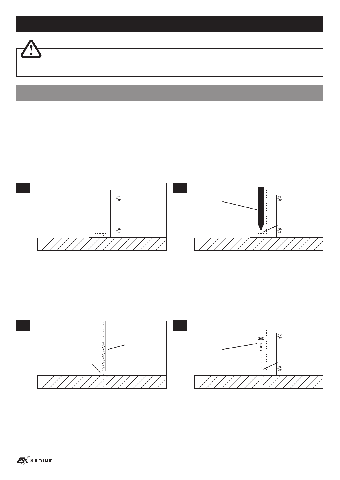
MECHANISCHE INSTALLATION
Achten Sie bei der Installation darauf, dass keine serienmäßig im KFZ vorhandenen Teile wie z.B. Kabel, Bordcomputer, Sicherheitsgurte, Tank oder ähnliche Teile beschädigt bzw.entfernt werden.
Vergewissern Sie sich, dass der Prozessor am Montageort genügend Kühlung erhält. Montieren Sie das Gerät nicht in zu kleine, abgeschlossene Gehäuse ohne Luftzirkulation, in die Nähe von wärmeabstrahlende Teilen oder elektronischen Steuerungen des Fahrzeuges.
Montieren Sie den Prozessor auf keinen Fall auf ein Bassgehäuse oder andere vibrierende Teile, dadurch können sich die Bauteile im
Prozessorinneren losvibrieren und das Gerät ernsthaft beschädigen.
Die Kabel der Stromversorgung und die Audiosignalkabel sollten bei dem Einbau so kurz als möglich gehalten werden, um Verluste und
Störungen zu vermeiden.
1
3
4 x
Suchen Sie zunächst einen geeigneten Einbauort für den
Prozessor. Achten Sie darauf, dass ausreichend Platz für
die Installation der Kabel vorhanden ist und diese nicht
geknickt werden sowie eine ausreichende Zugentlastung
gewährleistet ist.
4 x
Bohrer
2
4 x
Stift oder
Körner
Montageloch
Belassen Sie dann den Prozessor an der gewünschten
Einbaustelle im Fahrzeug. Markieren Sie die vier Bohrlöcher durch das jeweilige Montageloch an den Gussendteilen mit einem geeigneten Stift oder Körner.
4
4 x
Fixier-
Schraube
Markierung
Legen Sie dann den Prozessor beiseite und bohren dann
die Löcher für die Fixierschrauben an den zuvor markierten Punkten. Vergewissern Sie sich zuvor, dass keine Kabel, Leitungen und andere Komponenten des Fahrzeugs
beim Bohren beschädigt werden. Alternativ können Sie
auch (je nach Untergrund) selbstschneidende Gewindeschrauben verwenden.
Montageloch
Halten Sie dann den Prozessor wieder an die zuvor gewählte Position und verschrauben Sie den Prozessor mit
geeigneten Schrauben an den zuvor gebohrten Bohrlöchern mit dem Fahrzeug.
Achten Sie darauf, dass der verschraubte Prozessor fest
sitzt und sich während der Fahrt nicht losvibriert.
5
Page 6
HIGH LEVEL
INPUT
E / F / G / H
LINE OUT
SPEAKER
OUTPUT
BAT T.
+12V
GND
XE4240-DSP
4-CHANNEL AMPLIFIER WITH
DIGITAL SOUND PROCESSOR
POW.
PRT.
REMOTE
OPTICAL
INPUT
ON
ONLY WITH HIGH LEVEL INPUT
WiFi BOX
HIGH LEVEL
INPUT
SPEAKER
OUTPUT
F-
E-
SPEAKER
OUTPUT
BAT T.
+12V
XE6440-DSP
6-CHANNEL AMPLIFIER WITH
DIGITAL SOUND PROCESSOR
PRT.
AUX
INPUT
REM
IN/OUT
AUTO TURN ON
OFF
PC CONNECT USB
INSTALLATIONSHINWEISE
HIGH LEVEL
INPUT
SPEAKER
OUTPUT
BAT T.
+12V
GND
XE4240-DSP
4-CHANNEL AMPLIFIER WITH
DIGITAL SOUND PROCESSOR
POW.
PRT.
ON
ONLY WITH HIGH LEVEL INPUT
WiFi BOX
POW.
PRT.
AUX
INPUT
REM
IN/OUT
AUTO TURN ON
OFF
B
B1 Rechts Hinten +
B2 Rechts Hinten –
B3 Rechts Front +
B4 Rechts Front –
B5 Links Front +
B6 Links Front –
B7 Links Hinten +
B8 Links Hinten –
Lautsprecheranschlüsse
A1 Geschw.-Signal
A2 Tel.-Stummschalt.
A3 Ohne Verwend.
A4 +12V Dauerplus
A5 Antenne/Remote
A6 Beleuchtung
A7 +12V Schaltplus
A8 Masse
Systemanschlüsse
B1 Rechts Hinten +
B2 Rechts Hinten –
B3 Rechts Front +
B4 Rechts Front –
B5 Links Front +
B6 Links Front –
B7 Links Hinten +
B8 Links Hinten –
A
Lautsprecheranschlüsse
A1 Geschw.-Signal
A2 Tel.-Stummschalt.
A3 Ohne Verwend.
A4 +12V Dauerplus
A5 Antenne/Remote
A6 Beleuchtung
A7 +12V Schaltplus
A8 Masse
Systemanschlüsse
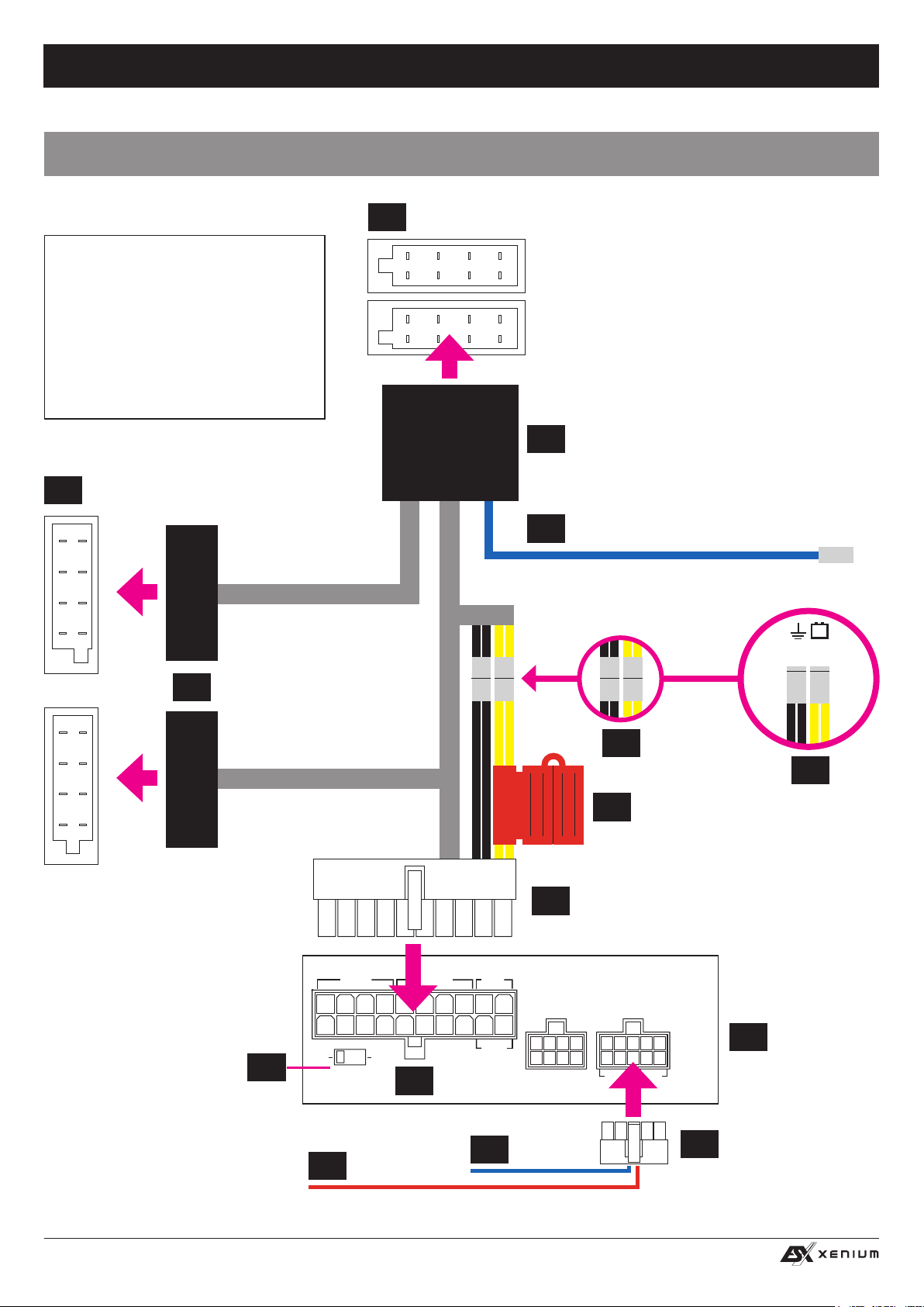
ELEKTRISCHE ANSCHLÜSSE
ISO-BELEGUNG*
Lautsprecheranschlüsse
B1 Rechts Hinten +
B2 Rechts Hinten –
B3 Rechts Front +
B4 Rechts Front –
B5 Links Front +
B6 Links Front –
B7 Links Hinten +
B8 Links Hinten –
Systemanschlüsse
A1 Geschw.-Signal
A2 Tel.-Stummschalt.
A3 Ohne Verwend.
A4 +12V Dauerplus
* Kann fahrzeugspezisch variieren, nicht alle Pins sind
wie oben beschrieben belegt.
A5 Antenne/Remote
A6 Beleuchtung
A7 +12V Schaltplus
A8 Masse
ISO-ANSCHLÜSSE
4
AUTORADIO
A
ISO-ANSCHLÜSSE
6
VOM FAHRZEUG
B
A
ISO-ANSCHLUSS
5
+12V SCHALTPLUS ZUR STROMVER-
13
SORGUNG WEITERER GERÄTE (optional)
OHNE SEPARATE
STROMVERSORGUNG
MIT SEPARATER
STROMVERSORGUNG
MASSE
FAHRZEUG
+12V
BATTERIE
B
14
8
HIGH LEVEL
INPUT
ON
AUTO TURN ON
ONLY WITH HIGH LEVEL INPUT
9
OFF
REM IN
SPEAKER
OUTPUT
2
BAT T.
+12V
11
GND
7A
GERÄTESICHERUNG 20A
FUSE
1
6-CHANNEL AMPLIFIER WITH
DIGITAL SOUND PROCESSOR
WiFi BOX
REM OUT
12
SYSTEM-KABELSATZ AUF ISO
XE6440-DSP
G/H
INPUT
LINE OUT
REM IN/OUT
AUX
3
AUDIO/AUX/REM-
10
KABELSATZ
–
7B
VERSTÄRKERBLENDE
+
6
Page 7

HIGH LEVEL
INPUT
E / F / G / H
LINE OUT
SPEAKER
OUTPUT
BAT T.
+12V
GND
XE4240-DSP
4-CHANNEL AMPLIFIER WITH
DIGITAL SOUND PROCESSOR
POW.
PRT.
REMOTE
OPTICAL
INPUT
ON
ONLY WITH HIGH LEVEL INPUT
WiFi BOX
HIGH LEVEL
INPUT
SPEAKER
OUTPUT
F-
E-
SPEAKER
OUTPUT
BAT T.
+12V
XE6440-DSP
6-CHANNEL AMPLIFIER WITH
DIGITAL SOUND PROCESSOR
PRT.
AUX
INPUT
REM
IN/OUT
AUTO TURN ON
OFF
PC CONNECT USB
INSTALLATIONSHINWEISE
VOR DEM ANSCHLIESSEN
• Bevor Sie mit der Installation des Soundsystems beginnen, trennen Sie bitte unbedingt den Massepol der Autobatterie ab, um Kurzschlüsse und Stromschläge zu vermeiden.
• Ziehen Sie vorsichtig Ihr Autoradio (Steuergerät) aus dem Radioschacht.
• Entfernen Sie die beiden ISO-Anschlüsse (#6) auf der Rückseite des Autoradios (#4).
ANSCHLUSS DES VERSTÄRKERS AN DAS AUTORADIO (STEUERGERÄT)
• Verlegen Sie den SYSTEM-KABELSATZ AUF ISO (#1) vom Verstärker zum Radioschacht,
• Stecken Sie den weißen Stecker (20-polig) in den Anschluss (#2) auf der Verstärkerblende (#3).
• Verbinden Sie die ISO-Stecker (#5) vom SYSTEM-KABELSATZ AUF ISO (#1) mit den ISO-Anschlüssen des Fahrzeugs, die Sie
zuvor vom Autoradio abgezogen haben (#6).
• Verbinden Sie die ISO-Stecker (#14) vom SYSTEM-KABELSATZ AUF ISO (#1) mit dem ISO-Anschluss des Autoradios (#4).
STROMVERSORGUNG
• Die Stromversorgung des Verstärkers über den SYSTEM-KABELSATZ AUF ISO (#1) ist nur für kleiner bis mittelgroße Soundsys-
teme geeignet. Über den Kabelsatz des Fahrzeugs stehen hier nur maximal 10 A zur Verfügung.
• Falls Sie mit dem Verstärker mehr Leistung für Ihre Lautsprecher benötigen und mit dem Verstärker zusätzlich noch einen Subwoofer betreiben möchten, muss eine separate Stromversorgung an den Verstärker angeschlossen werden.
• Lösen Sie dazu die jeweils die Steckverbindungen des schwarzen und gelben Kabels (#7A) am SYSTEM-KABELSATZ AUF ISO
(#1). Schließen Sie dann am gelben Kabel (#7B) eine +12V Leitung an, die direkt von der Fahrzeugbatterie über eine Sicherung
gespeist wird. Danach schließen Sie noch eine Verbindung von einem geeigneten Massepunkt an das schwarze Kabel (#7B) vom
SYSTEM-KABELSATZ AUF ISO (#1) an.
EINSCHALTLEITUNG (REM)
Der Verstärker kann mit der Funktion AUTO TURN ON (# 8, Automatische Einschaltfunktion) mit dem Ein- und Ausschal-
ten des Autoradios ebenfalls ein- und ausgeschaltet werden. Bringen Sie dazu den Schalter AUTO TURN ON (#8) in die Positi-
on „ON“. Das Gerät erkennt dann beim Einschalten des Steuergeräts durch einen sogenannten ”DC Offset” einen Spannungsanstieg auf 6 Volt an den angeschlossenen Hochpegel-Lautsprecherausgängen des Steuergeräts und schaltet dadurch den
Verstärker automatisch ein. Sobald das Steuergerät wieder abgeschaltet wird, schaltet sich der Verstärker wieder von selbst ab.
Hinweis: AUTO TURN ON funktioniert prinzipiell mit 90% aller Steuergeräte, da diese ”High Power”-Ausgänge besitzen. Mit einigen
wenigen älteren Autoradios kann AUTO TURN ON nicht genutzt werden. Schließen Sie dann eine geeignete +12V Einschaltleitung (z.B.
von der elektrischen Antenne) an das rote Kabel (#9, REM IN) des Steckers vom AUDIO/AUX/REM-KABELSATZ (#10) an
Tipp: Sollten Sie AUTO TURN ON verwenden, liegt am roten Kabel (#11, REM OUT) des Steckers vom AUDIO/AUX/REM-KABEL-
SATZ (#10) ein +12V Einschaltsignal an, welches Sie zum Anschalten weiterer Geräte verwenden können.
GERÄTESICHERUNG (FUSE)
Die 20A Gerätesicherung, welche das Gerät vor Kurzschlüssen und Überlastung schützt, bendet sich in dem roten Gehäuse (#12) am
SYSTEM-KABELSATZ AUF ISO (#1). Um eine defekte Sicherung auszutauschen, klemmen Sie zunächst das Gerät von der Stromver-
sorgung ab und klappen das rote Gehäuse auf. Verwenden Sie bitte nur eine gleichwertige Sicherung mit 20A.
OPTIONALES SCHALTPLUS
Sollten Sie für ein weiteres Gerät oder einen Verbraucher ein +12V Schaltplus (AAC), benötigen, können Sie hierfür das blaue Kabel
(#13) am ISO-Stecker (#5) vom SYSTEM-KABELSATZ AUF ISO (#1) verwenden. Hinweis: Das Kabel ist nicht bei allen Fahrzeugen
belegt.
VERWENDUNG EINES AUTORADIOS (STEUERGERÄTS) OHNE ISO-ANSCHLUSS
Sollte Ihr Autoradio nicht über einen herkömmlichen ISO-Anschluss verfügen, können Sie einen fahrzeugspe-
zischen ISO-Adapter passend für ihr Gerät/Fahrzeug aus dem Zubehörhandel beziehen.
Dazu müssen Sie dann lediglich diesen fahrzeugspezischen ISO-Adapter zwischen den ISO-Steckern und
ihrem Autoradio anschließen.
7
Page 8
HIGH LEVEL
INPUT
E / F / G / H
LINE OUT
SPEAKER
OUTPUT
BAT T.
+12V
GND
XE4240-DSP
4-CHANNEL AMPLIFIER WITH
DIGITAL SOUND PROCESSOR
POW.
PRT.
REMOTE
OPTICAL
INPUT
ON
ONLY WITH HIGH LEVEL INPUT
WiFi BOX
HIGH LEVEL
INPUT
SPEAKER
OUTPUT
F-
E-
SPEAKER
OUTPUT
BAT T.
+12V
XE6440-DSP
6-CHANNEL AMPLIFIER WITH
DIGITAL SOUND PROCESSOR
PRT.
AUX
INPUT
REM
IN/OUT
AUTO TURN ON
OFF
PC CONNECT USB
HIGH LEVEL
INPUT
E / F / G / H
LINE OUT
SPEAKER
OUTPUT
BAT T.
+12V
GND
XE4240-DSP
4-CHANNEL AMPLIFIER WITH
DIGITAL SOUND PROCESSOR
POW.
PRT.
REMOTE
OPTICAL
INPUT
ON
ONLY WITH HIGH LEVEL INPUT
WiFi BOX
AUX
INPUT
REM
IN/OUT
AUTO TURN ON
OFF
PC CONNECT USB
FUNKTIONSHINWEISE
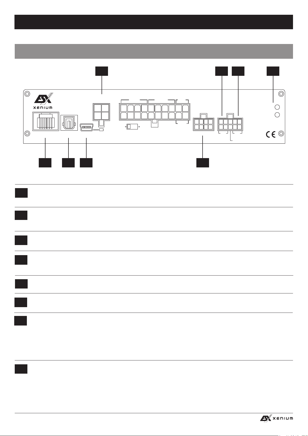
FUNKTIONEN UND BEDIENELEMENTE DES VERSTÄRKERS
1 42 3
E-
E+
HIGH LEVEL
INPUT
ON
AUTO TURN ON
ONLY WITH HIGH LEVEL INPUT
OFF
SPEAKER
OUTPUT
BAT T.
+12V
GND
XE6440-DSP
6-CHANNEL AMPLIFIER WITH
DIGITAL SOUND PROCESSOR
G/H
WiFi BOX
LINE OUT
AUX
INPUT
REM IN/OUT
REMOTE
SPEAKER
OUTPUT
F-
OPTICAL
F+
INPUT PC CONNECT USB
765 8
Anschluss für den LAUTSPRECHER AUSGANG-KABELSATZ (4-polig). An diesen können Sie zwei weitere Lautsprecher
1
mit einer Belastbarkeit von jeweils ca. 2 x 70/100 Watt RMS an 4/2 Ohm anschließen. Optional können Sie auch einen Subwoofer mit einer Belastbarkeit von ca. 200 Watt RMS/Max. an 4 Ohm gebrückt anschließen.
Anschluss für den AUDIO/AUX/REM-KABELSATZ (10-POLIG).
2
Die LINE OUT Cinchausgänge G/H dieses Kabelsatzes liefern ein lineares Vollbereichs-Audiosignal für die Ansteuerung weite-
rer Verstärker, welches mit der DSP-Software entsprechend modiziert werden kann.
Die AUX IN Cincheingänge können mit einer externen Audioquelle wie MP3-Player, Smartphones, Navigationsgeräte etc. ver-
3
bunden werden.
PRT.
POW.
POWER/PROTECT
4
Leuchtet die POWER LED, ist der Verstärker betriebsbereit.
Leuchtet die PROTECT LED, liegt eine Fehlfunktion vor. Beachten Sie dann die Hinweise im Abschnitt FEHLERBEHEBUNG.
Der Anschluss REMOTE dient zum Anschluss des Kabels der im Lieferumfang enthaltenen Fernbedienung (siehe folgende
5
Seite rechts).
Der Eingang OPTICAL INPUT dient mittels geeignetem Toslink-Kabel zum Anschluss einer externen Audioquelle, die ein
6
SPDIF-Signal (Stereo PCM) bereitstellt.
Verbinden Sie bei Bedarf den Mini-USB-Anschluss PC CONNECT mittels dem beiliegenden USB-Kabel mit Ihrem Computer,
7
auf dem die X-CONTROL Software installiert ist. Die Verbindung kann nach dem Benutzen der DSP-Software wieder gelöst
werden.
Verlängern Sie das Kabel auf keinen Fall mit einer passiven USB-Verlängerung, weil ansonsten eine einwandfreie Kommunikation zwischen dem DSP-Verstärker und dem PC nicht gewährleistet werden kann. Wenn Sie längere Distanzen zu
8
überbrücken haben, verwenden Sie bitte eine aktive USB-Verlängerung mit integriertem Repeater.
Die LED neben dem USB-Anschluss leuchtet blau auf, sobald eine Verbindung per USB-Kabel zwischen DSP-Gerät und
Computer hergestellt wurde.
Der Anschluss WIFI-BOX ist für das optional erhältliche Audio-Streaming-Modul, mit dem per W-LAN bspw. ein Smartphone
gekoppelt werden kann um ein Audiosignal an den Verstärker zu streamen.
8
Page 9
HIGH LEVEL
INPUT
E / F / G / H
LINE OUT
SPEAKER
OUTPUT
BAT T.
+12V
GND
XE4240-DSP
4-CHANNEL AMPLIFIER WITH
DIGITAL SOUND PROCESSOR
POW.
PRT.
REMOTE
OPTICAL
INPUT
ON
ONLY WITH HIGH LEVEL INPUT
WiFi BOX
HIGH LEVEL
INPUT
SPEAKER
OUTPUT
F-
E-
SPEAKER
OUTPUT
BAT T.
+12V
XE6440-DSP
6-CHANNEL AMPLIFIER WITH
DIGITAL SOUND PROCESSOR
PRT.
AUX
INPUT
REM
IN/OUT
AUTO TURN ON
OFF
PC CONNECT USB
FUNKTIONSHINWEISE
HIGH LEVEL
INPUT
E / F / G / H
LINE OUT
SPEAKER
OUTPUT
BAT T.
+12V
GND
XE4240-DSP
4-CHANNEL AMPLIFIER WITH
DIGITAL SOUND PROCESSOR
REMOTE
OPTICAL
INPUT
ON
ONLY WITH HIGH LEVEL INPUT
WiFi BOX
HIGH LEVEL
INPUT
SPEAKER
OUTPUT
F-
E-
SPEAKER
OUTPUT
BAT T.
+12V
XE6440-DSP
6-CHANNEL AMPLIFIER WITH
DIGITAL SOUND PROCESSOR
INPUT
REM
IN/OUT
AUTO TURN ON
OFF
PC CONNECT USB
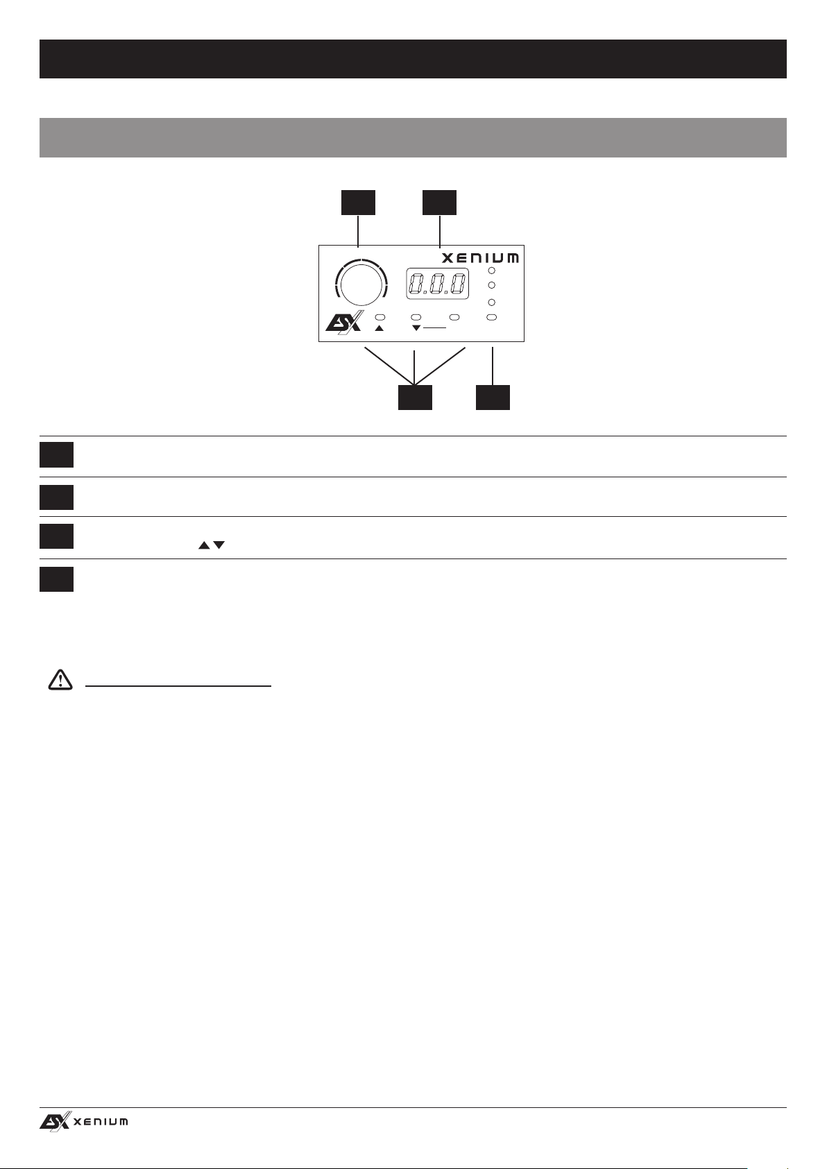
FUNKTIONEN UND BEDIENELEMENTE DER FERNBEDIENUNG
1 2
VOLUME
MAIN
AUX
–
Mit diesem Regler kann die Gesamtlautstärke des Soundsystems geregelt werden. Wenn Sie den Regler drücken und ca. 3
1
Sekunden halten kann damit auch der Basspegel von Ausgang LINE OUT (G/H) geregelt werden.
+
3 4
OPTICAL
INPUTMODE OK
2
3
4
Das LED-Display zeigt zum einen die Werte beim Drehen des Reglers (#1) oder die Nummer des gewählten Settings an.
Mit den beiden MODE-Tasten kann zwischen den im DSP gespeicherten Settings gewählt werden.
Wählen Sie mit den
Tasten das gewünschte Setting und bestätigen Sie die Auswahl mit OK (# 3).
Mit dem Taster INPUT kann zwischen den Eingängen der Audioquellen HIGH LEVEL INPUT, AUX INPUT und OPTICAL hinund her geschaltet werden.
Sollte an WiFi-BOX (siehe Seite 8, #8) das optionale Audio-Streaming-Modul angeschlossen und mit einer Audioquelle ge-
koppelt sein, wird diese automatisch als Eingangsquelle vom Verstärker erkannt und bleibt so lange aktiv, wie ein Audiosignal
abgespielt wird.
Wichtiger Bedienhinweis: Die Fernbedienung muss immer angeschlossen werden.
9
Page 10
HIGH LEVEL
INPUT
E / F / G / H
LINE OUT
SPEAKER
OUTPUT
BAT T.
+12V
GND
XE4240-DSP
4-CHANNEL AMPLIFIER WITH
DIGITAL SOUND PROCESSOR
POW.
PRT.
REMOTE
OPTICAL
INPUT
ON
ONLY WITH HIGH LEVEL INPUT
WiFi BOX
HIGH LEVEL
INPUT
SPEAKER
OUTPUT
F-
E-
SPEAKER
OUTPUT
BAT T.
+12V
XE6440-DSP
6-CHANNEL AMPLIFIER WITH
DIGITAL SOUND PROCESSOR
PRT.
AUX
INPUT
REM
IN/OUT
AUTO TURN ON
OFF
PC CONNECT USB
FUNKTIONSHINWEISE
INSTALLATION DER DSP-SOFTWARE
Die DSP Software X-CONTROL ist für alle Computer mit einem Windows™ Betriebssystem ab XP und einem USB-Anschluss geeignet.
Die Installation benötigt ca. 25 MB freien Speicherplatz. Prinzipbedingt sollte dafür ein tragbarer Laptop-Computer verwendet werden.
Legen Sie zunächst die beiliegende Software CD-ROM in das Computerlaufwerk ein oder laden Sie die DSP-Software X-CONTROL
über den Internetlink http://www.audiodesign.de/dsp herunter.
Starten Sie die setup.exe. Der Installationsassistent führt Sie durch die üblichen Schritte. Es wird empfohlen, eine Desktopverknüpfung
zu erstellen (Create a desktop icon). Nach der Installation sollte ein Neustart des Computers durchgeführt werden.
Wichtiger Hinweis zu 64 Bit Betriebssystemen: Bei 64 Bit Betriebssystem müssen Sie gegebenenfalls den 64-BIT Gerätetreiber
manuell installieren. Sie nden diesen auf der CD sowie ebenso unter http://www.audiodesign.de/dsp zum Download. Bei 32 Bit Betriebsystemen erfolgt die Treiberinstallation automatisch während der folgenden Programm-Installation.
KONFIGURATION DES PROZESSORS PER SOFTWARE
Zur Konguration des DSP-Prozessors sollte dieser nun per beiliegendem USB-Kabel mit dem Computer auf dem Sie die DSP-Software X-CONTROL installiert haben verbunden werden. Nach dem
Verbinden starten Sie das Programm auf dem Computer.
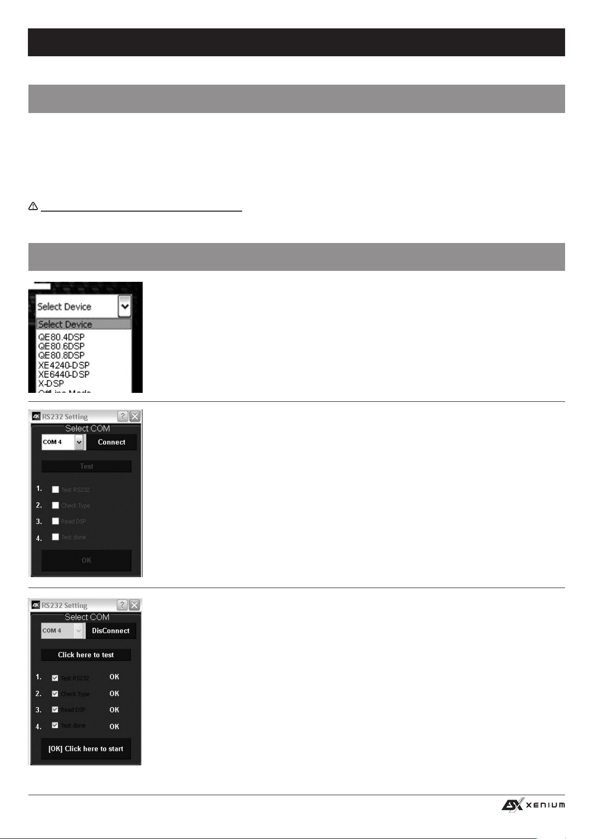
Nach dem Programmstart erscheint die Startmaske. Wählen Sie rechts unten unter Select Device Ihr
Gerät XE6440-DSP mit der Maus aus.
Demo-Modus (OffLine-Mode)
Sie können X-CONTROL auch ohne Verbindung mit dem DSP-Prozessor im Ofine-Modus starten und
sich mit den Funktionen der Software vertraut machen.
Stellen Sie im RS232 Setting die Verbindung mit dem DSP her. Die COM Schnittstelle sollte in der
Regel automatisch erkannt und ausgewählt werden, sie variiert von System zu System. Klicken Sie auf
Connect. Das Programm verbindet sich nun automatisch.
Sollte nach dem Auswählen von Connect nichts geschehen, beachten Sie die Hinweise im Kapitel
Fehlerbehebung auf Seite 20.
Hinweis: Der COM-Port wird automatisch vom Windows Betriebssystem zugewiesen. Beachten Sie,
dass der Port zwischen COM1 und COM9 liegen muss.
Klicken Sie auf Click here to test um die Verbindung zum DSP-Gerät zu prüfen
10
Page 11
HIGH LEVEL
INPUT
E / F / G / H
LINE OUT
SPEAKER
OUTPUT
BAT T.
+12V
GND
XE4240-DSP
4-CHANNEL AMPLIFIER WITH
DIGITAL SOUND PROCESSOR
POW.
PRT.
REMOTE
OPTICAL
INPUT
ON
ONLY WITH HIGH LEVEL INPUT
WiFi BOX
HIGH LEVEL
INPUT
SPEAKER
OUTPUT
F-
E-
SPEAKER
OUTPUT
BAT T.
+12V
XE6440-DSP
6-CHANNEL AMPLIFIER WITH
DIGITAL SOUND PROCESSOR
PRT.
AUX
INPUT
REM
IN/OUT
AUTO TURN ON
OFF
PC CONNECT USB
FUNKTIONSHINWEISE
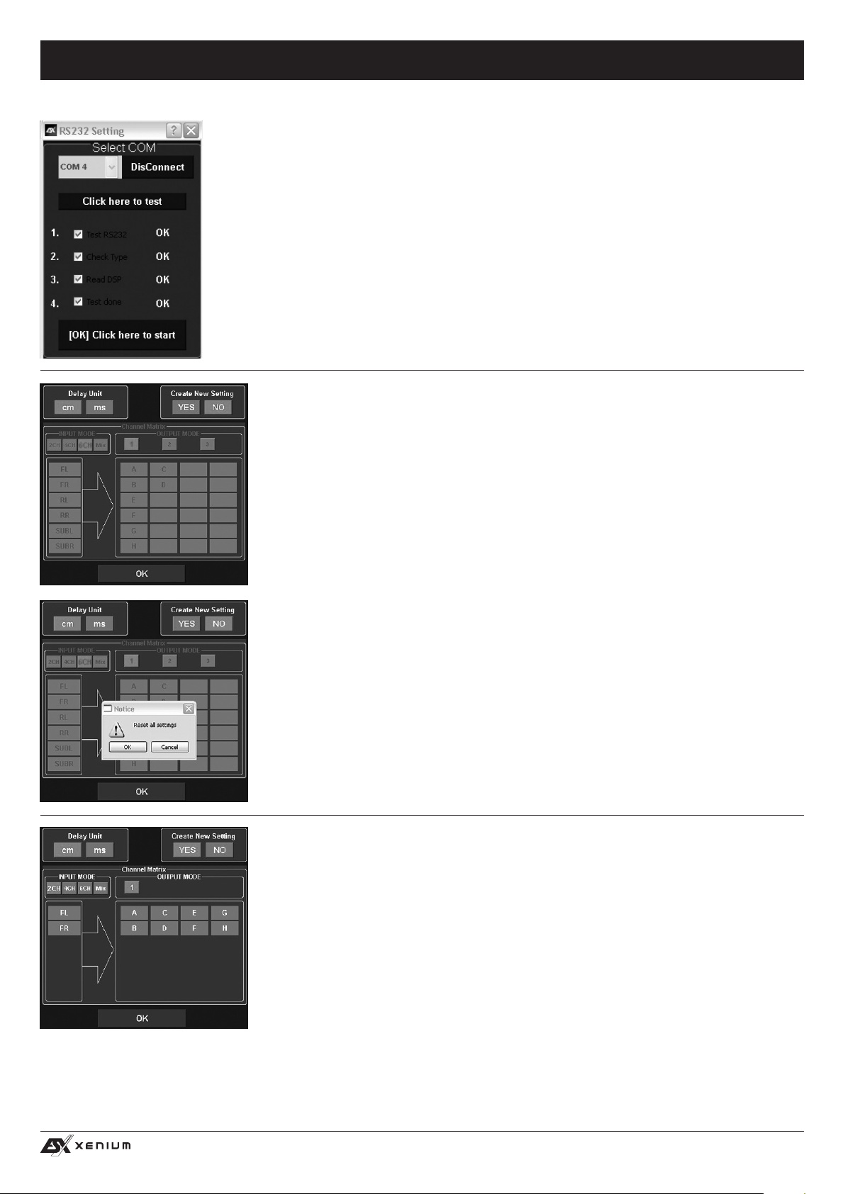
Wurde der Test erfolgreich durchgeführt erscheinen 4 Häkchen in den Checkboxen. Drücken
Sie dann auf [OK] Click here to start um fortzufahren.
Sollte eines der Häkchen bei einer Checkbox nicht erscheinen, liegt ein Problem vor welches
zu einer Fehlfunktion führen kann. Beachten Sie dazu die Angaben im Kapitel Fehlerbehe-
bung.
Als nächstes erscheint die Kongurationsmaske. Hier bestimmen Sie, wie viele Cinch/RCA
Audioeingänge Sie am DSP-Gerät belegen möchten und wie diese Signale an die jeweiligen
Cinch/RCA Audioausgängen ausgegeben werden sollen.
Wählen Sie unter Create New Setting:
- YES zum Erstellen eines neuen Settings.
Bestätigen Sie die Warnmeldung Reset all Settings mit OK.
- NO um das bestehende Setting beizubehalten.
Unter Delay Unit wählen Sie die Einheit für die Laufzeitkorrektur in Zentimeter [cm] oder in
Millisekunden [ms].
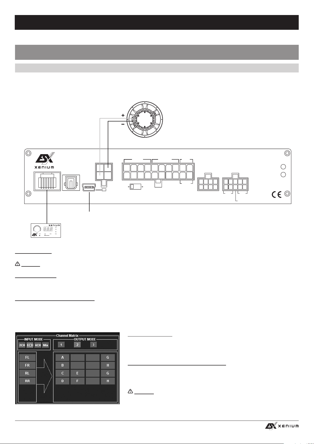
Channel Matrix
Unter INPUT MODE können Sie die Eingangskanäle des DSP-Prozessors entsprechend der
von Ihnen angeschlossenen Cinch/RCA Audioeingänge kongurieren.
Wählen Sie:
- 2CH, 4CH oder 6CH entsprechend der von Ihnen benutzten Chinchkabel
- Mix. Diese Funktion erzeugt ein Summensignal aus den LINE IN sowie
SUB IN Cinch/RCA Audioeingängen
Unter OUTPUT MODE können Sie die Eingänge den entsprechenden Ausgängen zuordnen.
Mit 1, 2 oder 3 (nur bei INPUT MODE 4CH und 6CH verfügbar) können Sie eine für Sie zutref-
fende Konguration wählen.
Klicken Sie dann auf OK um fortzufahren.
11
Page 12
HIGH LEVEL
INPUT
E / F / G / H
LINE OUT
SPEAKER
OUTPUT
BAT T.
+12V
GND
XE4240-DSP
4-CHANNEL AMPLIFIER WITH
DIGITAL SOUND PROCESSOR
POW.
PRT.
REMOTE
OPTICAL
INPUT
ON
ONLY WITH HIGH LEVEL INPUT
WiFi BOX
HIGH LEVEL
INPUT
SPEAKER
OUTPUT
F-
E-
SPEAKER
OUTPUT
BAT T.
+12V
XE6440-DSP
6-CHANNEL AMPLIFIER WITH
DIGITAL SOUND PROCESSOR
PRT.
AUX
INPUT
REM
IN/OUT
AUTO TURN ON
OFF
PC CONNECT USB
1
2
FUNKTIONSHINWEISE
BEDIENOBERFLÄCHE DER SOFTWARE
1 6
5
3
4
7
8
9
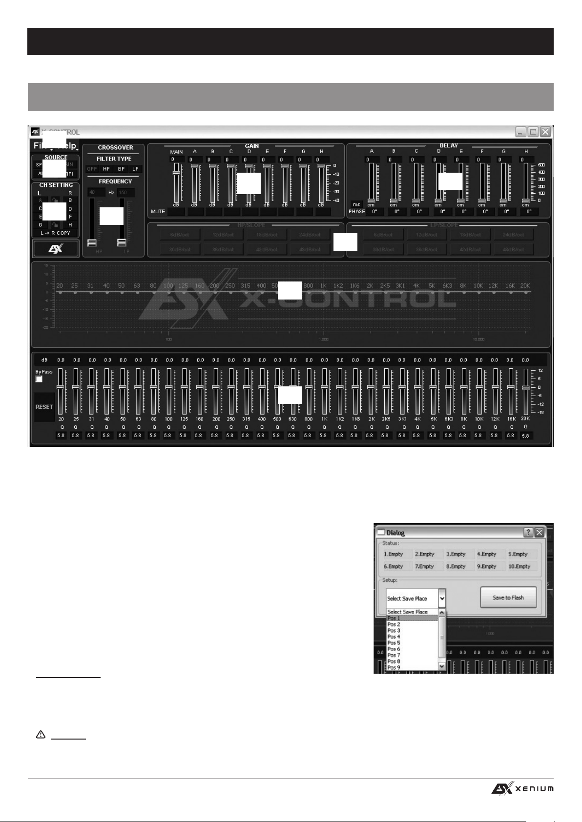
Hier können Sie unzählige Einstellungen vornehmen und an Ihr Soundsystem anpassen, welche in Echtzeit über den DSP-Prozessor so-
fort hörbar sind. Sobald Sie mit der Konguration eines Settings fertig sind, kann dieses auf den einen Speicherplatz im DSP-Prozessor
übertragen werden. Sie können bis zu 10 verschiedene Settings speichern und mit der Fernbedienung jederzeit im laufenden Betrieb
auswählen.
Im folgenden Abschnitt werden die einzelnen Funktionen der X-CONTROL Bedienoberäche erklärt.
1. File - Dropdown Menü:
• PC Contrl: Öffnet den RS232 Setting Dialog.
• Open: Öffnet ein auf dem PC zuvor gespeichertes Setting.
• Save: Speichert ein Setting in einer Datei auf dem PC mit dem aktuellen
verwendeten Dateinamen. Wurde zuvor noch kein Dateiname ausgewählt
fordert der Dialog Save File automatisch dazu auf.
• SaveAs: Speichert ein Setting unter einem bestimmten Dateinamen ab.
• Factory Setting: Setzt alle Einstellungen auf die Werkseinstellung zurück.
• Class-D AMP Setting: Ohne Funktion.
• Write To Device*: Speichert die Einstellungen im Gerät ab. Es folgt ein
Auswahlfenster, auf welchem Speicherplatz das Setting abgelegt werden soll.
• Wählen Sie unter Select Save Place einen Speicherplatz aus und bestätigen
Sie die Auswahl mit Save to Flash.
Bedienhinweis: Speichern Sie die Settings immer numerologisch (POS 1, POS 2,
POS 3,…) ab, damit diese mit der Fernbedienung aufgerufen werden können. Es dürfen keine Speicherplätze dazwischen unbelegt
bleiben, ansonsten sind die nachfolgenden Settings nicht aufrufbar. Siehe Dialog-Fenster oben.
• Read from Device*: Liest das an der Fernbedienung ausgewählte Setting aus dem DSP aus.
• Exit: Beendet X-CONTROL
*Wichtig: Dafür muss unbedingt die beiliegende Fernbedienung am DSP-Prozessor angeschlossen werden.
12
Page 13
HIGH LEVEL
INPUT
E / F / G / H
LINE OUT
SPEAKER
OUTPUT
BAT T.
+12V
GND
XE4240-DSP
4-CHANNEL AMPLIFIER WITH
DIGITAL SOUND PROCESSOR
POW.
PRT.
REMOTE
OPTICAL
INPUT
ON
ONLY WITH HIGH LEVEL INPUT
WiFi BOX
HIGH LEVEL
INPUT
SPEAKER
OUTPUT
F-
E-
SPEAKER
OUTPUT
BAT T.
+12V
XE6440-DSP
6-CHANNEL AMPLIFIER WITH
DIGITAL SOUND PROCESSOR
PRT.
AUX
INPUT
REM
IN/OUT
AUTO TURN ON
OFF
PC CONNECT USB
FUNKTIONSHINWEISE
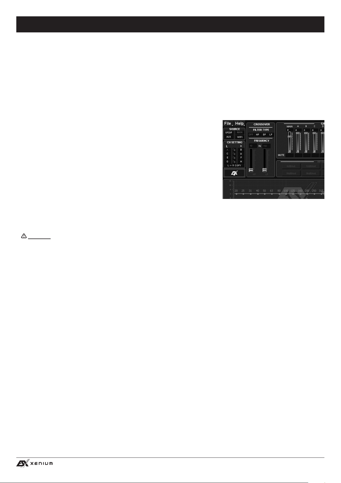
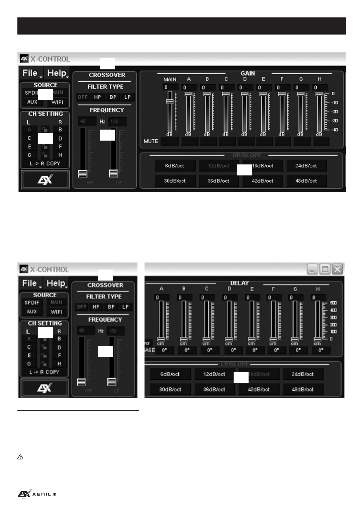
2. SOURCE:
• Hier wählen Sie zwischen den einzelnen Eingangsquellen OPTICAL (Optischer Eingang), MAIN (RCA/Cinch Audioeingänge) bzw.
HI LEVEL (Hochpegel-Audioeingänge), AUX (3,5 mm Klinke Stereoeingang) sowie WiFi (optional).
3. CH-SETTING:
• Hier wählen Sie den jeweiligen Ausgangskanal bzw. das Ausgangskanalpaar aus, bei welchem Sie die Einstellungen verändern
möchten.
Sie haben die Möglichkeit die jeweiligen Kanalpaare für L und R mit dem Schloss-Symbol in der Mitte miteinander zu verlinken um
die Einstellungen für beide Kanäle zu synchronisieren. Mit L-> R COPY können Sie zudem auch die Einstellung des zur Zeit gewählten linken Kanals auf den rechten Kanal kopieren.
4. CROSSOVER:
• Hier wählen Sie den gewünschten Filtertyp (FILTER TYPE OFF, HP, BP oder LP)
aus und bestimmen unter FREQUENCY die Trennfrequenz. Die Regler sind nur
bei aktiviertem Filter aktiv. Sobald ein Filtertyp ausgewählt wurde, wird dieser
sofort graphisch unter Punkt 8 dargestellt.
Bedienhinweis: Bei ausgewähltem Filter kann die Trennfrequenz auch direkt
unter Punkt 8 mit der Maus verändert werden. Klicken und Halten Sie hierzu
auf den roten Punkt und bewegen die Maus zur gewünschten Stelle auf
dem Frequenzband.
Tipp: Anstelle des Schiebereglers können Sie direkt die Trennfrequenz auch nach
einem Doppelklick auf die Werte unterhalb von FREQUENCY mit der Tastatur
eingeben. Bestätigen Sie die Eingabe mit ENTER.
5. GAIN:
• Hier können die Pegel der einzelnen Ausgänge A – H von 0dB bis -40dB reduziert werden. Mit den MUTE Feldern können Sie den jeweili-
gen Kanal stummschalten. Bei Bedarf können Sie MUTE unter dem Regler MAIN benutzen, um alle Ausgangskanäle stumm zu schalten.
Zudem kann unter MAIN die Gesamtlautstärke (-40dB bis +12dB) des DSP-Prozessors eingestellt werden.
Achtung: Benutzen Sie diesen Regler jedoch mit Bedacht. Ein zu lauter Pegel könnte Ihre Lautsprecher ernsthaft beschädigen.
6. DELAY:
• Hier können Sie die Laufzeitkorrektur sowie die Phasendrehung der einzelnen Ausgänge A – H einstellen. Für jeden Ausgangska-
nal kann die Laufzeitkorrektur des Signals unter DELAY individuell eingestellt werden. Oberhalb von PHASE kann die Einheit der
Verschiebung zwischen ms (Millisekunden) und cm (Zentimeter) umgeschaltet werden.
Tipp: Anstelle des Schiebereglers können Sie nach einem Doppelklick auf die Werte oberhalb der Schieberegler den gewünschten
Wert auch direkt mit der Tastatur eingeben. Bestätigen Sie die Eingabe mit ENTER.
• Unter den Schiebereglern kann rechts neben PHASE für jeden Kanal individuell die Phasedrehung von 0° auf 180° umgeschaltet
werden.
• Mit diesen beiden Funktionen können Sie das Soundsystem optimal an ihre Fahrzeugakustik anpassen und eine perfekte Feinein-
stellung der akustischen Bühne vornehmen.
7. HP SLOPE / LP SLOPE - KONFIGURATION DER FLANKENSTEILHEIT:
• Wählen Sie unter HP/SLOPE die gewünschte Flankensteilheit des Hochpasslters und unter LP/SLOPE die Flankensteilheit des
Tiefpasslters, welche von 6dB pro Oktave (sehr ach) bis 48dB pro Oktave (sehr steil) in 6dB Schritten auswählbar ist.
Bedienhinweis: Das HP/SLOPE bzw. LP/SLOPE Bedienfeld ist inaktiv (grau) wenn unter 4. CROSSOVER nicht entsprechend HP,
LP oder BP ausgewählt wurde.
8. FREQUENZBAND-VORSCHAU:
• Das Frequenzband zeigt die Hüllkurve des 31-Band Equalizers (Punkt 9.) sowie die unter Punkt 4. aktuell gewählten CROSSOVER-
Einstellungen des Ausgangskanals bzw. Ausgangskanalpaars grasch an.
9. 31-BAND EQUALIZER:
• Für jeden Ausgangskanal kann mit den Schiebereglern unten zwischen 20 Hz und 20000 Hz der gewünschte dB-Wert (-18 bis +12)
individuell eingestellt werden (ausgenommen Subwooferkanäle G & H: 11-Band Equalizer 20 Hz – 200 Hz).
Unterhalb der einzelnen Regler kann zusätzlich die Güte Q per Zahlenwert (0,5 für sehr ach bis 9 für sehr steil) eingegeben wer-
den.
Mit ByPass schalten Sie die Equalizer-Funktion ab.
Mit der Schaltäche RESET setzen Sie alle Einstellungen des Equalizers zurück (Alle anderen Einstellungen sind hiervon nicht
betroffen).
13
Page 14
HIGH LEVEL
INPUT
E / F / G / H
LINE OUT
SPEAKER
OUTPUT
BAT T.
+12V
GND
XE4240-DSP
4-CHANNEL AMPLIFIER WITH
DIGITAL SOUND PROCESSOR
POW.
PRT.
REMOTE
OPTICAL
INPUT
ON
ONLY WITH HIGH LEVEL INPUT
WiFi BOX
HIGH LEVEL
INPUT
SPEAKER
OUTPUT
F-
E-
SPEAKER
OUTPUT
BAT T.
+12V
XE6440-DSP
6-CHANNEL AMPLIFIER WITH
DIGITAL SOUND PROCESSOR
PRT.
AUX
INPUT
REM
IN/OUT
AUTO TURN ON
OFF
PC CONNECT USB
HIGH LEVEL
INPUT
E / F / G / H
LINE OUT
SPEAKER
OUTPUT
BAT T.
+12V
GND
XE4240-DSP
4-CHANNEL AMPLIFIER WITH
DIGITAL SOUND PROCESSOR
POW.
PRT.
REMOTE
OPTICAL
INPUT
ON
ONLY WITH HIGH LEVEL INPUT
WiFi BOX
AUX
INPUT
REM
IN/OUT
AUTO TURN ON
OFF
PC CONNECT USB
FUNKTIONSHINWEISE
HIGH LEVEL
INPUT
E / F / G / H
LINE OUT
SPEAKER
OUTPUT
BATT.
+12V
GND
XE4240-DSP
4-CHANNEL AMPLIFIER WITH
DIGITAL SOUND PROCESSOR
POW.
PRT.
REMOTE
OPTICAL
INPUT
ON
ONLY WITH HIGH LEVEL INPUT
WiFi BOX
HIGH LEVEL
INPUT
SPEAKER
OUTPUT
F-
E-
SPEAKER
OUTPUT
BATT.
+12V
XE6440-DSP
6-CHANNEL AMPLIFIER WITH
DIGITAL SOUND PROCESSOR
PRT.
AUX
INPUT
REM
IN/OUT
AUTO TURN ON
OFF
PC CONNECT USB
ANSCHLUSSBEISPIEL
5-Kanal-Modus: 2 x Stereo-System (Front & Rear) + 1 x Subwoofer
Subwoofer
4 – 8 Ohm
gebrückt
E-
E+
HIGH LEVEL
INPUT
ON
AUTO TURN ON
ONLY WITH HIGH LEVEL INPUT
OFF
SPEAKER
OUTPUT
BAT T.
+12V
GND
XE6440-DSP
6-CHANNEL AMPLIFIER WITH
DIGITAL SOUND PROCESSOR
G/H
WiFi BOX
LINE OUT
AUX
INPUT
REM IN/OUT
PRT.
POW.
REMOTE
SPEAKER
OUTPUT
F-
OPTICAL
F+
INPUT PC CONNECT USB
Beiliegendes USB-Kabel an
VOLUME
–
+
MAIN
AUX
Fernbedienung mit beiliegen-
OPTICAL
INPUTMODE OK
dem Kabel anschließen
den Computer anschließen
VERKABELUNG
• Schließen Sie den Subwoofer gebrückt bei F + und E – an.
Wichtig: Achten Sie darauf, dass die Gesamtimpedanz von 4 Ohm nicht unterschritten wird.
FERNBEDIENUNG
Siehe Seite 9. Die Regelung für den Basspegel bleibt weiterhin auf dem Ausgang LINE OUTPUT G/H und kann in diesem Anschlussbeispiel nicht an Ausgang E/F angewandt werden.
DSP-SOFTWARE EINSTELLUNGEN
Schließen Sie jetzt den DSP-Verstärker per beiliegendem USB-Kabel an den Computer an auf dem Sie die DSP-Software installiert haben.
Wichtig: Bis Sie alle Grundeinstellungen vorgenommen haben, sollten Sie den Volumen-Regler des Steuergeräts/Radios ganz nach
links auf die niedrigste Einstellung drehen um Schäden am Soundsystem zu vermeiden.
PROGRAMMSTART
Schalten Sie das Steuergerät (Autoradio) und damit den DSP-Verstärker ein.
Starten Sie die DSP-Software. Beachten Sie dazu auch die Angaben auf Seite
10 und 11.
KONFIGURATION DER EINGANGSKANÄLE
1. Wählen Sie unter INPUT MODE die Einstellung 4CH.
2. Wählen Sie unter OUTPUT MODE die Einstellung 2.
Hinweis: Sollten Sie keinen weiteren Verstärker mit dem Audioausgang LINE
OUTPUT G/H betreiben, müssen am Kanalpaar G/H keine Einstellungen vorgenommen werden.
14
Page 15
HIGH LEVEL
INPUT
E / F / G / H
LINE OUT
SPEAKER
OUTPUT
BAT T.
+12V
GND
XE4240-DSP
4-CHANNEL AMPLIFIER WITH
DIGITAL SOUND PROCESSOR
POW.
PRT.
REMOTE
OPTICAL
INPUT
ON
ONLY WITH HIGH LEVEL INPUT
WiFi BOX
HIGH LEVEL
INPUT
SPEAKER
OUTPUT
F-
E-
SPEAKER
OUTPUT
BAT T.
+12V
XE6440-DSP
6-CHANNEL AMPLIFIER WITH
DIGITAL SOUND PROCESSOR
PRT.
AUX
INPUT
REM
IN/OUT
AUTO TURN ON
OFF
PC CONNECT USB
FUNKTIONSHINWEISE
3
1
2
4
5
KONFIGURATION DER FRONT- & REAR-KANÄLE
1. Wählen Sie unter SOURCE die Einstellung MAIN.
2. Wählen Sie das Kanalpaar A & B (FL/FR) unter CH SETTING aus indem Sie auf das Schlosssymbol klicken.
3. Wählen Sie unter CROSSOVER > FILTER TYPE die Einstellung HP (Hochpasslter)
4. Wählen Sie unter CROSSOVER > FREQUENCY eine Trennfrequenz aus (zwischen 60Hz und 150 Hz)
5. Wählen Sie unter HP/SLOPE eine Flankensteilheit von 12dB/oct aus.
Wiederholen Sie die Punkte 2 – 5 für Kanalpaar C & D (RL/RR)
7
6
8
9
KONFIGURATION DES SUBWOOFER-KANALS
6. Wählen Sie das Kanalpaar E & F (SUB L/SUB R) unter CH SETTING aus indem Sie auf das Schlosssymbol klicken.
7. Wählen Sie unter CROSSOVER > FILTER TYPE die Einstellung BP (Bandpasslter)
8. Wählen Sie unter CROSSOVER > FREQUENCY eine Trennfrequenz für den HP zwischen 10Hz und 30 Hz und
für den LP zwischen 50Hz und 100 Hz aus.
9. Wählen Sie unter LP/SLOPE und HP/SLOPE eine Flankensteilheit von 18dB/oct aus.
Hinweis: Die angegebenen Frequenzwerte sind nur Richtwerte, die je nach Größe und Beschaffenheit der Lautsprecher und der
Akustik im Fahrzeug variieren können.
15
Page 16

HIGH LEVEL
INPUT
E / F / G / H
LINE OUT
SPEAKER
OUTPUT
BAT T.
+12V
GND
XE4240-DSP
4-CHANNEL AMPLIFIER WITH
DIGITAL SOUND PROCESSOR
POW.
PRT.
REMOTE
OPTICAL
INPUT
ON
ONLY WITH HIGH LEVEL INPUT
WiFi BOX
HIGH LEVEL
INPUT
SPEAKER
OUTPUT
F-
E-
SPEAKER
OUTPUT
BAT T.
+12V
XE6440-DSP
6-CHANNEL AMPLIFIER WITH
DIGITAL SOUND PROCESSOR
PRT.
AUX
INPUT
REM
IN/OUT
AUTO TURN ON
OFF
PC CONNECT USB
FUNKTIONSHINWEISE
ANPASSUNG DER LAUTSTÄRKEPEGEL
Passen Sie die Pegel der einzelnen Kanäle nach Ihren Wünschen passend zu den Audiokomponenten und Gegebenheiten im Fahrzeuginneren an.
Beachten Sie hierzu folgende Hinweise:
• Senken Sie die Ausgangslautstärke unter MAIN auf -10dB ab um Verzerrungen zu vermeiden.
• Spielen Sie qualitativ hochwertige Musik von ihrem Steuergerät ab. Deaktivieren Sie alle klangbeeinussenden Regler des Steuer-
gerätes wie EQ und Loudness und bringen Sie Balance und Fader in die Mittelstellung. Drehen Sie jetzt den Volumen-Regler des
Steuergerätes/Autoradios behutsam auf ca. 80-90% der maximalen Lautstärke.
• Erhöhen Sie beim Einpegeln unter MAIN schrittweise den Pegel bis leichte Verzerrungen aus den Lautsprechern zu hören sind.
Verringern Sie dann den Pegel ein wenig bis keine Verzerrungen mehr hörbar sind.
• Unter GAIN können Sie die Pegel der einzelnen Ausgangskanäle (A-H) auch separat nochmals absenken
Hinweis: Vermeiden Sie das Erhöhen des Lautstärkepegels eines einzelnen Ausgangkanals um ihn lauter zu stellen. Reduzieren
Sie stattdessen besser die Pegel der anderen Ausgänge.
Achtung: Benutzen Sie diese Regler jedoch mit Bedacht. Ein zu lauter Pegel könnte Ihre Lautsprecher ernsthaft beschädigen.
KONFIGURATION DES EQUALIZERS
Stellen Sie den Equalizer nach Ihren Wünschen und Hörgewohnheiten ein. Beachten Sie, dass Sie zuerst den gewünschten Kanal bzw.
das gewünschte Kanalpaar (Schlosssymbol) auswählen müssen und danach die Equalizer-Einstellung verändern!
KONFIGURATION DER LAUFZEITKORREKTUR UND PHASENDREHUNG
Stellen Sie die Laufzeitkorrektur (DELAY) und Phasendrehung (PHASE) nach Ihren Wünschen passend zu den Audiokomponenten und
Gegebenheiten im Fahrzeuginnern ein. Beachten Sie dazu den Praxistipp auf Seite 18.
SPEICHERN DER EINSTELLUNGEN
Speichern Sie nun bei Bedarf das Preset unter File mittels Save (Speichern) oder SaveAs (Speichern unter) auf Ihrem Computer.
ÜBERTRAGUNG DES SETTINGS ZUM DSP-VERSTÄRKER
Speichern Sie Ihr Setting auf einem der Speicherplätze im DSP wie auf Seite 10 beschrieben
MODIFIZIEREN EINES BESTEHENDEN SETTINGS
Sollten Sie ein bestehendes Setting, welches bereits auf dem DSP-Verstärker gespeichert wurde, modizieren wollen, klicken Sie unter
File auf Read From Device. Hierzu müssen Sie den auszulesenden Speicherplatz (POS 1 – POS10) vorher an der Fernbedienung
auswählen und aktivieren (siehe Seite 7 und 10).
Die Daten werden dann in die DSP-Software geladen und können entsprechend verändert werden. Danach können Sie unter File auf
Write To Device das neue Setting wieder auf den DSP-Verstärker speichern.
Wichtig: Dafür muss unbedingt die beiliegende Fernbedienung am DSP-Verstärker angeschlossen werden.
16
Page 17

HIGH LEVEL
INPUT
E / F / G / H
LINE OUT
SPEAKER
OUTPUT
BAT T.
+12V
GND
XE4240-DSP
4-CHANNEL AMPLIFIER WITH
DIGITAL SOUND PROCESSOR
POW.
PRT.
REMOTE
OPTICAL
INPUT
ON
ONLY WITH HIGH LEVEL INPUT
WiFi BOX
HIGH LEVEL
INPUT
SPEAKER
OUTPUT
F-
E-
SPEAKER
OUTPUT
BAT T.
+12V
XE6440-DSP
6-CHANNEL AMPLIFIER WITH
DIGITAL SOUND PROCESSOR
PRT.
AUX
INPUT
REM
IN/OUT
AUTO TURN ON
OFF
PC CONNECT USB
FUNKTIONSHINWEISE
WEITERES ANSCHLUSSBEISPIEL
Kanäle Beispiel
Front mit Vollbereichslautsprechern
Rear mit Kickbässen und Vollbereichslautsprechern
Separater Subwoofer-Verstärker
Input Mode 4CH
Output Mode 2
A
B
C
D
Lautsprecher (FL)
HP 60 - 150 Hz
Lautsprecher (FR)
HP 60 - 150 Hz
Lautsprecher (RL)
HP 60 - 150 Hz
Lautsprecher (RR)
HP 60 - 150 Hz
Kickbass (RL)
E
F
G
H
BP:
HP 60 Hz
LP 150 Hz
Kickbass (RR)
BP:
HP 60 Hz
LP 150 Hz
Externer Verstärker:
Subwoofer
BP:
HP 10-30 Hz
LP 50 - 100 Hz
Weiterer Verstärker benötigt
17
Page 18

HIGH LEVEL
INPUT
E / F / G / H
LINE OUT
SPEAKER
OUTPUT
BAT T.
+12V
GND
XE4240-DSP
4-CHANNEL AMPLIFIER WITH
DIGITAL SOUND PROCESSOR
POW.
PRT.
REMOTE
OPTICAL
INPUT
ON
ONLY WITH HIGH LEVEL INPUT
WiFi BOX
HIGH LEVEL
INPUT
SPEAKER
OUTPUT
F-
E-
SPEAKER
OUTPUT
BAT T.
+12V
XE6440-DSP
6-CHANNEL AMPLIFIER WITH
DIGITAL SOUND PROCESSOR
PRT.
AUX
INPUT
REM
IN/OUT
AUTO TURN ON
OFF
PC CONNECT USB
PRAXISTIPP: LAUFZEITKORREKTUR
170120 80 0 00 0
0
0
0
Wie stelle ich in der DSP-Software den richtigen Abstand der Laufzeitkorrektur ein, um alle Lautsprecher des Soundsystems aufeinander
einzustellen und der Schall gleichzeitig beim Hörer ankommt?
1. Messen Sie zuerst den Abstand der Lautsprecher zur akustischen Bühnenmitte. In diesem Fall ist diese der Fahrersitz auf
Höhe der Ohren.
2. Der virtuelle Nullwert zum Einstellen der Abstände in der DSP-Software richtet sich nach dem am weitesten entfernten
Lautsprecher. In diesem Fall ist dies der Subwoofer hinten im Fahrzeugs mit einem Abstand von 250 cm.
3. Ziehen Sie nun die gemessenen Abständen von 250 cm ab und stellen diesen Wert am jeweiligen Kanal in der DSP-Software ein (siehe graue Abmessungen unten).
FRONT L
Kanal A
180
REAR L
Kanal C
170
70 cm
180 cm
80 cm
170 cm
250 cm
130 cm
120 cm
170 cm
80 cm
FRONT R
Kanal B
120
REAR R
Kanal D
80
18
Hinweis: Sie können die
Werte auch direkt per
Tastatur in die Eingabefelder über den Schiebereglern eingeben.
SUBWOOFER
Kanal E/F
0
0
Page 19

HIGH LEVEL
INPUT
E / F / G / H
LINE OUT
SPEAKER
OUTPUT
BAT T.
+12V
GND
XE4240-DSP
4-CHANNEL AMPLIFIER WITH
DIGITAL SOUND PROCESSOR
POW.
PRT.
REMOTE
OPTICAL
INPUT
ON
ONLY WITH HIGH LEVEL INPUT
WiFi BOX
HIGH LEVEL
INPUT
SPEAKER
OUTPUT
F-
E-
SPEAKER
OUTPUT
BAT T.
+12V
XE6440-DSP
6-CHANNEL AMPLIFIER WITH
DIGITAL SOUND PROCESSOR
PRT.
AUX
INPUT
REM
IN/OUT
AUTO TURN ON
OFF
PC CONNECT USB
ALLGEMEINE HINWEISE
TECHNISCHE DATEN
MODELL
KANÄLE
SCHALTUNGSPRINZIP
KANAL A/B/C/D
AUSGANGSLEISTUNG RMS 13,8 V
Watt an 4 / 2 Ohm
AUSGANGSLEISTUNG MAX. 13,8 V
Watt an 4 / 2 Ohm
KANAL E/F
AUSGANGSLEISTUNG RMS 13,8 V
Watt an 4 / 2 Ohm
Watt an 4 Ohm gebrückt
AUSGANGSLEISTUNG MAX. 13,8 V
Watt an 4 / 2 Ohm
Watt an 4 Ohm gebrückt
Frequenzgang –3dB
Dämpfungsfaktor
Signal-Rauschabstand
Kanaltrennung
Klirrfaktor (THD&N)
Eingangsempndlichkeit
Eingangsimpedanz
DSP-Prozessor
Hochpegel-Audioeingänge per Kabelsatz
Niedrigpegel-Audioausgänge Cinch/RCA
Weitere Eingänge
XE6440-DSP
6
CLASS D Digital
4 x 40/60
4 x 80 /120
2 x 70/100
1 x 140/200
2 x 140/200
1 x 280/400
5 Hz - 20 kHz
> 100
> 90 dB
> 60 dB
0,05%
4 - 0,3 V
> 47 kOhm
Cirrus Logic Single Core 32 bit, 8-Kanal, 192 kHz
FL / FR / RL / RR
G (CH 7) / H (CH 8)
TOSLINK (HD Audio, optisch, 12 ~ 96 kHz, stereo)
AUX (Cinch/RCA, stereo)
WiFi-Box (optionales Streaming-Modul, stereo)
Automatische Einschaltfunktion (Auto Turn On)
Schaltbar, Bei Verwendung liegt ein +12V Einschaltsteuersignal an REM OUT für weitere Geräte an
für Microsoft Windows™
X-CONTROL DSP-Software
XP SP3, Vista, 7, 8, 8.1
10 Presets, Gain -40 ~ +12dB
6 x 31-Band Equalizer, 2 x 11-Band Equalizer, -18 ~ 12 dB, Güte 0,5 ~ 9
Einstellbereich 20 ~ 20.000 Hz (Ausgänge A-F), 20 ~ 200 Hz (Ausgänge G-H)
6 ~ 48 db/Okt. HP/BP/LP
Laufzeitkorrektur 0~15 ms/0~510 cm
Phasendrehung 0°/180°
Fernbedienung mit LED-Display
für Master Volume, Subwoofer Volume,
Eingangsmodus, Speicherplatzauswahl
Sicherungswert
Abmessungen (Breite x Höhe x Länge)
Technische Änderungen und Irrtümer vorbehalten!
Die Garantieleistung entspricht der gesetzlichen Regelung in Ihrem Land. Von der Garantieleistung ausgeschlossen sind Defekte und
Schäden, die durch Überlastung, unsachgemäße Behandlung oder durch Teilnahme an Wettbewerben entstanden sind. Schicken Sie
das defekte Produkt mit einem gültigen Kaufbeleg und einer detaillierten Fehlerbeschreibung an Ihren Fachhändler, bei dem Sie das
Produkt erworben haben.
1 x 20 A
120 x 40 x 216 mm
GARANTIEHINWEIS
Alle ESX Verstärker sind mit einer individuelle Seriennummer versehen, die für statistische und servicebedingte Zwecke aufgezeichnet
wird. Alle ESX Verstärker sind zudem mit einer CE-Kennzeichnung versehen. Damit sind die Geräte für den Betrieb in Fahrzeugen inner-
halb der Europäischen Union (EU) zertiziert.
19
Page 20

HIGH LEVEL
INPUT
E / F / G / H
LINE OUT
SPEAKER
OUTPUT
BAT T.
+12V
GND
XE4240-DSP
4-CHANNEL AMPLIFIER WITH
DIGITAL SOUND PROCESSOR
POW.
PRT.
REMOTE
OPTICAL
INPUT
ON
ONLY WITH HIGH LEVEL INPUT
WiFi BOX
HIGH LEVEL
INPUT
SPEAKER
OUTPUT
F-
E-
SPEAKER
OUTPUT
BAT T.
+12V
XE6440-DSP
6-CHANNEL AMPLIFIER WITH
DIGITAL SOUND PROCESSOR
PRT.
AUX
INPUT
REM
IN/OUT
AUTO TURN ON
OFF
PC CONNECT USB
FEHLERBEHEBUNG
Fehler: keine Funktion
Ursache: Lösung:
1. Die Stromversorgungskabel sind nicht korrekt angeschlossen. Erneute Überprüfung
2. Die Kabel haben keinen elektrischen und mechanischen Kontakt. Erneute Überprüfung
3. Die Remote-Steuerleitung des Steuergeräts (Autoradio) ist nicht korrekt am Verstärker angeschlossen. Erneute Überprüfung
4. Sicherungen defekt. Im Falle des Austauschs achten Sie bitte auf den korrekten Wert der Sicherungen. Sicherungen austauschen
Fehler: kein Ton aus Lautsprecher, aber Power LED leuchtet
Ursache: Lösung:
1. Die Lautsprecherkabel oder Cinchkabel sind nicht korrekt angeschlossen. Erneute Überprüfung
2. Die Lautsprecherkabel oder Cinchkabel sind defekt. Kabel ersetzen
3. Die Lautsprecher sind defekt. Lautsprecher ersetzen
4. HP Regler in Betriebsart LP/BP zu hoch eingestellt. Regler runterdrehen
5. Kein Signal vom Steuergerät (Radio) Steuergerät-Einstellungen prüfen
6. Falsche Audioquelle unter INPUT SOURCE ausgewählt, die nicht angeschlossen ist (z.B. AUX IN) Auswahl prüfen
7. In der DSP-Software ist z.B. „Mute“ für einen oder alle Kanäle aktiviert. Einstellungen prüfen
8. Lautstärke an der Fernbedienung ist zu niedrig eingestellt Volume-Regler höher drehen
Fehler: Ein bzw. mehrere Kanäle oder Regler sind ohne Funktion / fehlerhaftes Stereobild
Ursache: Lösung:
1. Der Balance- bzw. Fader-Regler am Steuergerät ist nicht in der Mittel-Position. Auf Nullwert stellen
2. Ein Kabel an Lautsprecher oder Verstärker hat sich gelöst. Erneute Überprüfung
3. Die Lautsprecher sind defekt. Lautsprecher ersetzen
4. HP Regler in Betriebsart LP/BP zu hoch eingestellt. Regler runterdrehen
5. In der DSP-Software ist z.B. „Delay“ oder „Phase“ für einen oder alle Kanäle falsch eingestellt. Einstellungen prüfen
Fehler: Verzerrungen aus Lautsprecher
Ursache: Lösung:
1. Die Lautsprecher sind überlastet. Pegel niedriger einstellen
Pegel am Steuergerät niedriger einstellen
Loudness am Steuergerät abschalten
Bass EQ am Steuergerät neu einstellen
Fehler: Keine Bässe bzw. kein Stereo-Sound
Ursache: Lösung:
1. Beim Anschluss sind an den Lautsprechern bzw. Kabeln plus (+) und minus (-) vertauscht worden. Erneuter korrekter Anschluss
2. Die Cinchkabel sind lose, falsch angeschlossen oder beschädigt/defekt. Erneuter korrekter Anschluss oder ersetzen
3. In der DSP-Software ist z.B. „Delay“ oder „Phase“ für einen oder alle Kanäle falsch eingestellt. Einstellungen prüfen
Fehler: Verstärker schaltet in den Schutz-Modus (rote Protect-LED leuchtet)
Ursache: Lösung:
1. Kurzschluss an den Lautsprechern bzw. Kabeln. Erneuter korrekter Anschluss
2. Überhitzung durch zu niedrige Impedanz der Lautsprecher. Andere höhere Impedanz wählen
Neue Lautsprecheranordnung wählen
3. Mangelnde Luftzufuhr durch ungünstigen Einbau-Ort des Verstärkers. Anderer Einbauort wählen
Für Luftzufuhr sorgen
4. Überlastung durch Strommangel (zu dünne Kabelquerschnitte bei den Stromkabeln). Größerer Kabelquerschnitt installieren
Fehler: Rauschen aus den Lautsprechern
Ursache: Lösung:
1. Die GAIN-Regler in der DSP-Software sind zu hoch eingestellt. GAIN-Regler niedriger einstellen
2. Der Hochton-Regler am Steuergerät ist voll aufgedreht. Pegel am Steuergerät niedriger einstellen
3. Die Lautsprecherkabel oder Cinchkabel sind defekt oder beschädigt. Kabel ersetzen
4. Das Rauschen kommt vom Steuergerät. Steuergerät überprüfen lassen
20
Page 21

HIGH LEVEL
INPUT
E / F / G / H
LINE OUT
SPEAKER
OUTPUT
BAT T.
+12V
GND
XE4240-DSP
4-CHANNEL AMPLIFIER WITH
DIGITAL SOUND PROCESSOR
POW.
PRT.
REMOTE
OPTICAL
INPUT
ON
ONLY WITH HIGH LEVEL INPUT
WiFi BOX
HIGH LEVEL
INPUT
SPEAKER
OUTPUT
F-
E-
SPEAKER
OUTPUT
BAT T.
+12V
XE6440-DSP
6-CHANNEL AMPLIFIER WITH
DIGITAL SOUND PROCESSOR
PRT.
AUX
INPUT
REM
IN/OUT
AUTO TURN ON
OFF
PC CONNECT USB
FEHLERBEHEBUNG
Fehler: kein Ton vom Subwoofer
Ursache: Lösung:
1. Die Lautstärke des Subwoofer-Ausgangs (Kanal G/H bzw. SUB OUT) ist an der Fernbedienung zu leise eingestellt. Regler der Fernbedienung drücken
und halten, Lautstärke erhöhen wie
auf Seite. 7 beschrieben.
Fehler: „ERROR“-Meldung bei Verbindung zwischen DSP-Gerät und Computer
Ursache: Lösung:
1. Der DSP-Verstärker ist im PROTECT-Modus (Schutzschaltung) oder nicht eingeschaltet Beheben Sie die Ursache
Hinweis: Die POWER LED sowie die USB LED müssen blau leuchten
Fehler: „The COM port could not open...“-Meldung bei Verbindung zwischen DSP-Gerät und Computer
Ursache: Lösung:
1. Im Verbindungsfenster nach dem Software-Start wurde der falsche COM Port ausgewählt oder festgelegt. Wählen Sie den richtigen Port aus.
Der Port muss zwischen COM1 und COM9 liegen. Prüfen Sie bei Bedarf den Port im
Geräte-Manager in Windows unter
„Anschlüsse (COM&LPT),
Eintrag „USB-Serial CH340“.
Fehler: Die gespeicherten Settings lassen sich nicht an der Fernbedienung per Mode-Taste abrufen
Ursache: Lösung:
1. Die Settings müssen numerologisch gespeichert werden (POS1, POS2, POS3, ...) Speichern Sie die Settings immer
numerologisch ab (Siehe Seite 10).
21
Page 22

HIGH LEVEL
INPUT
E / F / G / H
LINE OUT
SPEAKER
OUTPUT
BAT T.
+12V
GND
XE4240-DSP
4-CHANNEL AMPLIFIER WITH
DIGITAL SOUND PROCESSOR
POW.
PRT.
REMOTE
OPTICAL
INPUT
ON
ONLY WITH HIGH LEVEL INPUT
WiFi BOX
HIGH LEVEL
INPUT
SPEAKER
OUTPUT
F-
E-
SPEAKER
OUTPUT
BAT T.
+12V
XE6440-DSP
6-CHANNEL AMPLIFIER WITH
DIGITAL SOUND PROCESSOR
PRT.
AUX
INPUT
REM
IN/OUT
AUTO TURN ON
OFF
PC CONNECT USB
FEHLERBEHEBUNG
STÖRUNGEN / INTERFERENZEN
Die Ursache von Interferenzen sind meist immer die verlegten Kabel. Besonders anfällig dafür sind die Strom- und Cinchkabel des
Sound Systems. Oftmals werden Interferenzen durch Generatoren (Lichtmaschine) oder andere elektronische Steuergeräte des KFZ
(Benzinpumpe, Klimaanlage etc.) verursacht. Die meisten dieser Probleme können durch korrektes und sorgfältiges Verkabeln vermieden werden.
Hier nden Sie dazu einige Hilfestellungen:
1. Benutzen Sie nur mehrfach abgeschirmte hochwertige Cinch Audiokabel für die Anschlüsse zwischen Verstärker und
Steuergerät. Eine brauchbare Alternative sind im Zubehörhandel erhältliche Entstörmaßnahmen. Verwenden Sie möglichst
keine Entstörlter, welche die Masse am Cinch/RCA-Audiokabel auftrennen.
2. Verlegen Sie die Signal-, Lautsprecher- und Stromkabel separat mit ausreichendem Abstand zueinander und
ebenso zu jedem anderen Kabel im Fahrzeug. Benutzen Sie dazu die verschiedenen Kabelkanäle des Fahrzeugs.
Sollte diese nicht möglich sein, können Sie das Stromkabel zusammen mit den seriellen Kabeln im Fahrzeug verlegen.
Die Cinch Audiokabel sollten soweit wie möglich von diesen entfernt liegen. Das Kabel der Einschaltleitung des
Steuergeräts (Remote) kann zusammen mit dem Cinch Audiokabel verlegt werden.
3. Vermeiden Sie Masse-Schleifen indem Sie die Masse-Verbindungen aller Komponenten in einer sternförmigen
Anordnung verlegen. Den geeigneten Masse-Mittelpunkt können Sie durch Messen der Spannung direkt an der
Batterie ermitteln. Messen Sie mit einem Multi-Meter die Spannung der Fahrzeug-Batterie. Sie sollten
diese Messung bei eingeschalteter Zündung und angeschalteten Verbrauchern (z.B. Licht, Heckscheibenheizung)
durchführen. Diesen Wert müssen Sie dann mit dem von Ihnen gewählten Masse-Punkt und dem Plus-Terminal (+12V)
des Verstärkers vergleichen. Wenn die gemessenen Spannungen nur geringfügig voneinander abweichen, haben Sie
den richtigen Masse-Punkt gefunden. Andernfalls müssen Sie einen anderen Punkt wählen.
4. Benutzen Sie möglichst Kabel mit angesetzten oder verlöteten Kabelschuhen oder dergleichen. Vergoldete oder
hochwertig vernickelte Kabelschuhe sind korrosionsfrei und haben einen geringeren Kontakt-Widerstand.
SCHUTZSCHALTUNG
Im Verstärker sind verschiedene elektronische Schutzsicherungen integriert. Bei Überlastung, Überhitzung, Kurzschluss an den Lautsprechern, aber auch bei zu niederohmigen Betrieb oder mangelhafter Stromversorgung schaltet dieser ab, um größeren Schäden vorzubeugen. Liegt eine der oben genannten Störungen vor, leuchtet die PROTECT LED (rot) auf.
Prüfen Sie in diesem Fall alle Anschlüsse auf Fehler, wie. z.B. Kurzschlüsse, fehlerhafte Verbindungen oder Überhitzung. Gehen sie
dabei wie auf der nächsten Seite beschrieben vor.
Wenn die Störung (z.B. Überhitzung) beseitigt wurde, kann der Verstärker wieder in Betrieb genommen werden.
Erlischt die Störung/Protect-LED nicht, liegt ein Defekt am Verstärker vor. In diesem Fall bitten wir Sie, das Gerät mit einer detaillierten
Fehlerbeschreibung und einer Kopie des Kaufbelegs an Ihren Fachhändler zu retournieren.
ACHTUNG: Öffnen Sie keinesfalls den Verstärker und versuchen diesen selbst zu reparieren, dies hat einen Garantieverlust zur Folge.
Diese Reparaturmaßnahmen sollten nur von geschulten Technikern durchgeführt werden.
INSTALLATION IN NEUEREN FAHRZEUGEN
In Fahrzeugen neueren Baujahrs (ab ca. 2002) kommen in der Regel computergestützte Diagnose- und Kontrollsysteme zum Einsatz,
u.a. mit CAN-BUS- und MOST-BUS-Schnittstellen. Durch die Installation des Car Audio Verstärkers kommt ein weiterer Stromverbraucher
an das 12 Volt Bordnetz des Fahrzeugs, der unter Umständen durch hohe Spannungsspitzen und durch einen erhöhten Stromverbrauch
das ab Werk installierte Diagnose- und Kontrollsystem stört, bzw. Fehlermeldungen verursacht. Dadurch könnte, je nach Fahrzeugtyp
und Hersteller, die Fahrsicherheit bzw. wichtige Sicherheitssysteme wie Airbags, Stabilitätskontrolle und ähnliches gestört werden.
Sollten Sie den Verstärker in einem neueren Fahrzeug wie oben beschrieben betreiben wollen, gehen Sie bitte wie folgt vor:
1. Lassen Sie die Installation nur von einem entsprechend geschulten Einbauspezalisten durchführen, am besten von einer
Service-Werkstatt, die auf die Wartung und Reparatur Ihres Fahrzeugs spezialisiert und mit der Technik des Fahrzeugs vertraut ist.
2. Nach der Installation sollte unter allen Umständen eine computergestützte Diagnose des Fahrzeugsystems von Ihrer
Service-Werkstatt durchgeführt werden, um eventuelle Störungen und Fehlermeldungen erkennen zu können.
3. Sollte das Bordnetz bzw. die Sicherheitssysteme durch die Installation des Car Audio Verstärkers gestört werden, können mit
Hilfe von parallel geschalteten Pufferkondensatoren die etwaigen auftretenden Störungen im Bordnetz ausgeglichen werden.
Ein stabiler und sachgemäßer Betrieb des Fahrzeugs kann somit gewährleistet werden.
4. Die beste Lösung stellt jedoch die Installation eines zweiten 12 Volt Stromnetzes für das Soundsystem dar, welches unabhängig
von der Fahrzeugelektrik betrieben werden kann und über eine eigene Batterieversorgung verfügt.
SUCHEN SIE FALLS MÖGLICH IHRE SERVICE-WERKSTATT AUF UND LASSEN SIE SICH BERATEN!
22
Page 23

HIGH LEVEL
INPUT
E / F / G / H
LINE OUT
SPEAKER
OUTPUT
BAT T.
+12V
GND
XE4240-DSP
4-CHANNEL AMPLIFIER WITH
DIGITAL SOUND PROCESSOR
POW.
PRT.
REMOTE
OPTICAL
INPUT
ON
ONLY WITH HIGH LEVEL INPUT
WiFi BOX
HIGH LEVEL
INPUT
SPEAKER
OUTPUT
F-
E-
SPEAKER
OUTPUT
BAT T.
+12V
XE6440-DSP
6-CHANNEL AMPLIFIER WITH
DIGITAL SOUND PROCESSOR
PRT.
AUX
INPUT
REM
IN/OUT
AUTO TURN ON
OFF
PC CONNECT USB
NOTITZEN
23
Page 24

HIGH LEVEL
INPUT
E / F / G / H
LINE OUT
SPEAKER
OUTPUT
BAT T.
+12V
GND
XE4240-DSP
4-CHANNEL AMPLIFIER WITH
DIGITAL SOUND PROCESSOR
POW.
PRT.
REMOTE
OPTICAL
INPUT
ON
ONLY WITH HIGH LEVEL INPUT
WiFi BOX
HIGH LEVEL
INPUT
SPEAKER
OUTPUT
F-
E-
SPEAKER
OUTPUT
BAT T.
+12V
XE6440-DSP
6-CHANNEL AMPLIFIER WITH
DIGITAL SOUND PROCESSOR
PRT.
AUX
INPUT
REM
IN/OUT
AUTO TURN ON
OFF
PC CONNECT USB
SCOPE OF DELIVERY
1 x XE6440-DSP Amplier
1 x Remote Controller with LED Display, incl. Connection Cable
1 x USB Cable, A- to Mini-B Connector, 5 m
1 x System Cable-Set on ISO-Plug, 2 m
1 x Speaker Output Cable-Set (4-pin)
1 x Audio/AUX/REM Cable-Set (10-pin)
1 x CD-ROM with X-CONTROL Software
1 x Owner‘s Manual (German/English)
24
Page 25

HIGH LEVEL
INPUT
E / F / G / H
LINE OUT
SPEAKER
OUTPUT
BAT T.
+12V
GND
XE4240-DSP
4-CHANNEL AMPLIFIER WITH
DIGITAL SOUND PROCESSOR
POW.
PRT.
REMOTE
OPTICAL
INPUT
ON
ONLY WITH HIGH LEVEL INPUT
WiFi BOX
HIGH LEVEL
INPUT
SPEAKER
OUTPUT
F-
E-
SPEAKER
OUTPUT
BAT T.
+12V
XE6440-DSP
6-CHANNEL AMPLIFIER WITH
DIGITAL SOUND PROCESSOR
PRT.
AUX
INPUT
REM
IN/OUT
AUTO TURN ON
OFF
PC CONNECT USB
TABLE OF CONTENT
SAFETY INSTRUCTIONS 26
INSTALLATION INSTRUCTIONS 27
Mechanical installation ....................................................................................................................27
Electrical interconnection.................................................................................................................28
FUNCTIONAL INSTRUCTIONS 30
Features and operational controls ................................................................................................... 30
Installation of the DSP software ......................................................................................................32
Amplier conguration with the software ......................................................................................... 33
User Interface of the software .........................................................................................................34
Interconnection example .................................................................................................................36
Additional interconnection example ................................................................................................. 39
Practice hint: Time Delay .................................................................................................................40
GENERAL NOTES 41
Specications ..................................................................................................................................41
Warranty ..........................................................................................................................................41
TROUBLE SHOOTING 42
Due to the ongoing development of this device, it is possible that the information in this manual is incomplete or is not matching to the
delivery status.
NOTE
This symbol shows you important notes on the following pages. Follow these notes necessarily, otherwise damages of the
device and on the vehicle as well as serious injuries may be caused.
PLEASE KEEP THIS MANUAL FOR LATER PURPOSES!
25
Page 26

HIGH LEVEL
INPUT
E / F / G / H
LINE OUT
SPEAKER
OUTPUT
BAT T.
+12V
GND
XE4240-DSP
4-CHANNEL AMPLIFIER WITH
DIGITAL SOUND PROCESSOR
POW.
PRT.
REMOTE
OPTICAL
INPUT
ON
ONLY WITH HIGH LEVEL INPUT
WiFi BOX
HIGH LEVEL
INPUT
SPEAKER
OUTPUT
F-
E-
SPEAKER
OUTPUT
BAT T.
+12V
XE6440-DSP
6-CHANNEL AMPLIFIER WITH
DIGITAL SOUND PROCESSOR
PRT.
AUX
INPUT
REM
IN/OUT
AUTO TURN ON
OFF
PC CONNECT USB
SAFETY INSTRUCTIONS
PLEASE NOTE THE FOLLOWING ADVICE BEFORE THE FIRST OPERATION!
THE PURCHASED DEVICE IS ONLY SUITABLE FOR AN OPERATION
WITH A 12V ON-BOARD ELECTRICAL SYSTEM OF A VEHICLE. Other-
wise re hazard, risk of injury and electric shock consists.
PLEASE DO NOT MAKE ANY OPERATION OF THE SOUNDSYSTEM,
WHICH DISTRACT YOU FROM A SAFE DRIVING. Do not make any pro-
cedures, which demand a longer attention. Perform these operations not
until you have stopped the vehicle on a safe place. Otherwise the risk of
accident consists.
ADJUST THE SOUND VOLUME TO AN APPROPRIATE LEVEL, THAT
YOU ARE STILL ABLE TO HEAR EXTERIOR NOISES WHILE DRIVING.
High performance sound systems in vehicles may generate the acoustic
pressure of a live concert. The permanent listening to extreme loud music
may cause the loss of your hearing abilities. The hearing of extreme loud
music while driving may derogate your cognition of warning signals in the
trafc. In the interests of the common safeness, we suggest to drive with a
lower sound volume. Otherwise the risk of accident consists.
DO NOT COVER COOLING VENTS AND HEATSINKS. Otherwise this
may cause heat accumulation in the device and re hazard consists.
DO NOT OPEN THE DEVICE. Otherwise re hazard, risk of injury and
electric shock consists. Also this may cause a loss of the warranty.
REPLACE FUSES ONLY WITH FUSE WITH THE SAME RATING. Other-
wise re hazard and risk of electric shock consists.
DO NOT USE THE DEVICE ANY LONGER, IF A MALFUNCTION, WHICH
REMAINS UNREMEDIED. Refer in this case to the chapter TROUBLE
SHOOTING. Otherwise risk of injury and the damage of the device consists. Commit the device to an authorized retailer.
THE INSTALLATION OF A POWER CAPACITOR WITH SUFFICIENT CAPACITY IS RECOMMENDED. High performance ampliers cause high po-
tential voltage drops and need a high power consumption at a high volume
level. To relieve the vehicle’s on-board system, it is recommended to install
a power capacitor between the battery and the device which works as buffer. Consult your car audio retailer for the appropriate capacity.
INTERCONNECTION AND INSTALLATION SHOULD BE ACCOMPLISHED BY SKILLED STAFF ONLY. The interconnection and installation
of this device demands technical aptitude and experience. For your own
safeness, commit the interconnection and installation to your car audio retailer, where you have purchased the device.
DISCONNECT THE GROUND CONNECTION FROM THE VEHICLE’S
BATTERY BEFORE INSTALLATION. Before you start with the installation
of the sound system, disconnect by any means the ground supply wire from
the battery, to avoid any risk of electric shock and short circuits.
DO NOT INSTALL THE DEVICE AT LOCATIONS, WHERE IT WILL BE
EXPOSED TO HIGH HUMIDITY AND DUST. Install the device at a loca-
tion, where it will be protected from high humidity and dust. If humidity and
dust attain inside the device, malfunctions may be caused.
MOUNT THE DEVICE AND OTHER COMPONENTS OF THE SOUND
SYSTEM SUFFICIENTLY. Otherwise the device and components may get
loose and act as dangerous objects, which could cause serious harm and
damages in the passenger room.
ENSURE NOT TO DAMAGE COMPONENTS, WIRES AND CABLES OF
THE VEHICLE WHEN YOU DRILL THE MOUNTING HOLES. If you drill
the mounting holes for the installation into the vehicle’s chassis, ensure by
any means, not to damage, block or tangent the fuel pipe, the gas tank,
other wires or electrical cables.
ENSURE CORRECT CONNECTION OF ALL TERMINALS. Faulty con-
nections may could cause re hazard and lead to damages of the device.
DO NOT INSTALL AUDIO CABLES AND POWER SUPPLY WIRES TOGETHER. Ensure while installation not to lead the audio cables between
the head unit and the amplier together with the power supply wires on the
same side of the vehicle. The best is a areal separated installation in the left
and right cable channel of the vehicle. Therewith a overlap of interferences
on the audio signal will be avoided. This stands also for the equipped bassremote wire, which should be installed not together with the power supply
wires, but rather with the audio signal cables.
ENSURE THAT CABLES MAY NOT CAUGHT UP IN CLOSE-BY OBJECTS. Install all the wires and cables like described on the following pag-
es, therewith these may not hinder the driver. Cables and wires which are
installed close-by the steering wheel, gear lever or the brake pedal, may
caught up and cause highly dangerous situations.
DO NOT SPLICE ELECTRICAL WIRES. The electrical wires should not be
bared, to provide power supply to other devices. Otherwise the load capacity of the wire may get overloaded. Use therefor a appropriate distribution
block. Otherwise re hazard and risk of electric shock consists.
DO NOT USE BOLTS AND SCREW NUTS OF THE BRAKE SYSTEM
AS GROUND POINT. Never use for the installation or the ground point
bolts and screw-nuts of the brake system, steering system or other security-
relevant components. Otherwise re hazard consists or the driving safety
will be derogated.
ENSURE NOT TO BEND OR SQUEEZE CABLES AND WIRES BY
SHARP OBJECTS. Do not install cables and wires not close-by movable
objects like the seat rail or may bent or harmed by sharp and barbed edges.
If you lead a wire or cable through the hole in a metal sheet, protect the
insulation with a rubber grommet.
CHOOSE AN APPROPRIATE LOCATION FOR THE INSTALLATION OF
THE DEVICE. Look for an appropriate location for the device, which en-
sures a sufcient air circulation. The best places are spare wheel cavities,
and open spaces in the trunk area. Less suitable are storage spaces behind
the side coverings or under the car seats.
26
KEEP AWAY SMALL PARTS AND JACKS FROM CHILDREN. If objects
like these will be swallowed, the risk of serious injuries consists. Consult
immediately a medical doctor, if a child swallowed a small object.
Page 27

HIGH LEVEL
INPUT
E / F / G / H
LINE OUT
SPEAKER
OUTPUT
BAT T.
+12V
GND
XE4240-DSP
4-CHANNEL AMPLIFIER WITH
DIGITAL SOUND PROCESSOR
POW.
PRT.
REMOTE
OPTICAL
INPUT
ON
ONLY WITH HIGH LEVEL INPUT
WiFi BOX
HIGH LEVEL
INPUT
SPEAKER
OUTPUT
F-
E-
SPEAKER
OUTPUT
BAT T.
+12V
XE6440-DSP
6-CHANNEL AMPLIFIER WITH
DIGITAL SOUND PROCESSOR
PRT.
AUX
INPUT
REM
IN/OUT
AUTO TURN ON
OFF
PC CONNECT USB
INSTALLATION INSTRUCTIONS
NOTE
Before you start with the installation of the sound system, disconnect necessarily the GROUND connection wire from the
battery to avoid any risk of electric shocks and short circuits.
MECHANICAL INSTALLATION
Avoid any damages on the components of the vehicle like air bags, cables, board computer, seat belts, gas tank or the like.
Ensure that the choosen location provides a sufcient air circulation for the processor. Do not mount the device into small or sealed
spaces without air circulation near by heat dispersing parts or electrical parts of the vehicle.
Do not mount the processor on top of a subwoofer box or any other vibrating parts, whereby parts could loosen inside.
The wires and cables of power supply and the audio signal must be as short as possible to avoid any losses and interferences.
1
3
4 x
At rst you need to nd a suitable installation location for
the processor. Ensure that enough space for the installation of the cables remains and that they will not bent and
have sufcient pull relief.
4 x
Drill
2
4 x
Pen or
peening
tool
Keep the processor at the choosen mounting location in
the vehicle. Then mark the four drill holes with an appropriate pen or peening tool through the designated mounting holes at the processor.
4
4 x
Mounting
screw
Marking
Lay the processor aside and then drill the holes for the
mounting screws at the marked locations.
Please ensure not to damage any components of the vehicle while you drilling the holes. Alternatively (depends
on the material of the surface) you can also use self-tapping screws.
Then uphold the processor to the choosen position and
x the screws through the mounting holes into the drilled
screw holes.
Ensure that the mounted processor is tightly xed and
can not come loose while driving.
27
Page 28

HIGH LEVEL
INPUT
E / F / G / H
LINE OUT
SPEAKER
OUTPUT
BAT T.
+12V
GND
XE4240-DSP
4-CHANNEL AMPLIFIER WITH
DIGITAL SOUND PROCESSOR
POW.
PRT.
REMOTE
OPTICAL
INPUT
ON
ONLY WITH HIGH LEVEL INPUT
WiFi BOX
HIGH LEVEL
INPUT
SPEAKER
OUTPUT
F-
E-
SPEAKER
OUTPUT
BAT T.
+12V
XE6440-DSP
6-CHANNEL AMPLIFIER WITH
DIGITAL SOUND PROCESSOR
PRT.
AUX
INPUT
REM
IN/OUT
AUTO TURN ON
OFF
PC CONNECT USB
INSTALLATION INSTRUCTIONS
HIGH LEVEL
INPUT
SPEAKER
OUTPUT
BAT T.
+12V
GND
XE4240-DSP
4-CHANNEL AMPLIFIER WITH
DIGITAL SOUND PROCESSOR
POW.
PRT.
ON
ONLY WITH HIGH LEVEL INPUT
WiFi BOX
POW.
PRT.
AUX
INPUT
REM
IN/OUT
AUTO TURN ON
OFF
B
B1 Rechts Hinten +
B2 Rechts Hinten –
B3 Rechts Front +
B4 Rechts Front –
B5 Links Front +
B6 Links Front –
B7 Links Hinten +
B8 Links Hinten –
Lautsprecheranschlüsse
A1 Geschw.-Signal
A2 Tel.-Stummschalt.
A3 Ohne Verwend.
A4 +12V Dauerplus
A5 Antenne/Remote
A6 Beleuchtung
A7 +12V Schaltplus
A8 Masse
Systemanschlüsse
B1 Rechts Hinten +
B2 Rechts Hinten –
B3 Rechts Front +
B4 Rechts Front –
B5 Links Front +
B6 Links Front –
B7 Links Hinten +
B8 Links Hinten –
A
Lautsprecheranschlüsse
A1 Geschw.-Signal
A2 Tel.-Stummschalt.
A3 Ohne Verwend.
A4 +12V Dauerplus
A5 Antenne/Remote
A6 Beleuchtung
A7 +12V Schaltplus
A8 Masse
Systemanschlüsse
B
B1 Rechts Hinten +
B2 Rechts Hinten –
B3 Rechts Front +
B4 Rechts Front –
B5 Links Front +
B6 Links Front –
B7 Links Hinten +
B8 Links Hinten –
A
Lautsprecheranschlüsse
A1 Geschw.-Signal
A2 Tel.-Stummschalt.
A3 Ohne Verwend.
A4 +12V Dauerplus
A5 Antenne/Remote
A6 Beleuchtung
A7 +12V Schaltplus
A8 Masse
Systemanschlüsse
ELECTRICAL INTERCONNECTION
ISO-ASSIGNMENT*
Speaker Connections
B1 Right Rear +
B2 Right Rear –
B3 Right Front +
B4 Right Front –
B5 Left Front +
B6 Left Front –
B7 Left Rear +
B8 Left Rear –
System Connections
A1 Speed Signal
A2 Phone Mute
A3 Not in use
A4 +12V Battery
* Varies vehicle-specic, not all pins are occupied as
described above.
A5 Antenna/Remote
A6 Illumination
A7 +12V Switched
A8 Ground
ISO-CONNECTORS
4
CAR STEREO / HEAD UNIT
A
ISO-CONNECTORS
6
OF THE VEHICLE
B
A
ISO-CONNECTOR
5
+12V AAC FOR THE POWER SUPPLY
13
OF ADDITIONAL DEVICES (optional)
WITHOUT SEPARATE
POWER SUPPLY
WITH SEPARATE
POWER SUPPLY
VEHICLE
+12V
BATTERY
GROUND
B
28
14
8
HIGH LEVEL
INPUT
ON
AUTO TURN ON
ONLY WITH HIGH LEVEL INPUT
OFF
REM IN
9
SPEAKER
OUTPUT
2
FUSE
1
BAT T.
+12V
GND
11
XE6440-DSP
6-CHANNEL AMPLIFIER WITH
DIGITAL SOUND PROCESSOR
WiFi BOX
REM OUT
7A
FUSE OF THE DEVICE 20A
12
SYSTEM CABLE-SET ON ISO
3
AUX
G/H
INPUT
LINE OUT
REM IN/OUT
AUDIO/AUX/REM
10
CABLE-SET
–
+
7B
AMPLIFIER
PANEL
Page 29

HIGH LEVEL
INPUT
E / F / G / H
LINE OUT
SPEAKER
OUTPUT
BAT T.
+12V
GND
XE4240-DSP
4-CHANNEL AMPLIFIER WITH
DIGITAL SOUND PROCESSOR
POW.
PRT.
REMOTE
OPTICAL
INPUT
ON
ONLY WITH HIGH LEVEL INPUT
WiFi BOX
HIGH LEVEL
INPUT
SPEAKER
OUTPUT
F-
E-
SPEAKER
OUTPUT
BAT T.
+12V
XE6440-DSP
6-CHANNEL AMPLIFIER WITH
DIGITAL SOUND PROCESSOR
PRT.
AUX
INPUT
REM
IN/OUT
AUTO TURN ON
OFF
PC CONNECT USB
INSTALLATION INSTRUCTIONS
BEFORE CONNECTING
• Before you start with the installation of the sound system, disconnect necessarily the GROUND connection wire from the battery to
avoid any risk of electric shocks and short circuits.
• Carefully remove your car stereo/head unit from the radio bay.
• Unplug both ISO-Connectors (#6) on the back side of your car stereo/head unit (#4).
INTERCONNECTION OF THE CAR STEREO/HEAD UNIT TO THE AMPLIFIER
• Lay the SYSTEM CABLE-SET ON ISO (#1) from the amplier to the radio bay.
• Plug the white connector (20-pin) into the terminal (#2) on the amplier panel (#3)
• Connect the ISO-Plugs (#5) of the SYSTEM CABLE-SET ON ISO (#1) with the ISO-Connectors of the vehicle, which you have
unplugged before (#6).
• Connect the ISO-Plugs (#14) of the SYSTEM CABLE-SET ON ISO (#1) with the ISO-Connectors of the car stereo/head unit (#4).
POWER SUPPLY
• The power supply of the amplier via the SYSTEM CABLE-SET ON ISO (#1) is only suitable for smaller and midsize sound systems.
The cable-set of the vehicle delivers only a max. power supply of 10 A.
• If you need more power for your amplier and the speakers and you want to operate a subwoofer additionally, a separate power
supply must be connected to the amplier.
• Therefor, unplug the connections of the black and yellow cables (#7A) on the SYSTEM CABLE-SET ON ISO (#1). Then connect
a +12V connection to the yellow plug (#7B), which is fed directly from the vehicle battery via a fuse. After that, connect a suitable
ground connection to the black plug (#7B) of the SYSTEM CABLE-SET ON ISO (#1), which is connected with the vehicle’s chassis.
TURN-ON SIGNAL
By using the function AUTO TURN ON (# 8), the amplier can be turned on or off along with the car stereo/head unit. Therefor, set the
switch AUTO TURN ON (# 8) to position “ON”. The amplier detects now by a so called ”DC Offset” (a voltage increase up to 6 volts) on
the high level speaker outputs. Then, if the head unit is turned on the amplier turns automatically on. As soon as the head unit is turned
off, the amplier shuts down automatically.
Note: The AUTO TURN ON usually works with 90% of all head units, because they are equipped with the ”High Power” outputs.
Only with a few older head units the AUTO TURN ON function is not applicable.
Hint: If you use the AUTO TURN ON function, a +12V remote turn-on signal is routed to the blue cable (#11, REM OUT) of the AUDIO/
AUX/REM CABLE-SET, which you can use for turning on other devices.
FUSE OF THE DEVICE
The 20 A fuse, which protect the device against short circuits and overload, is located inside the red housing (#12) of the SYSTEM
CABLE-SET ON ISO (#1). To replace a defective fuse, rst clamp off the device from the power supply. Then open the red housing of the
device and replace the defective fuse with a new fuse of the same type and same rating (20 A).
OPTIONAL AAC-SIGNAL
If you require a +12V ignition signal (AAC) for additional devices, use therefor the blue cable (#13) at the ISO-Connector (#5) of the SYSTEM CABLE-SET ON ISO (#1). Note: This cable is not occupied on all vehicles.
USING A CAR STEREO / HEAD UNIT WITHOUT ISO-CONNECTORS
If your car stereo/head unit does not have a conventional ISO-Connector, you can purchase a vehicle-spe-
cic ISO-Adapter suitable for your device/vehicle from the accessories trade.
Then connect this vehicle-specic ISO-Adapter between the ISO-Connectors and your car stereo/head unit.
29
Page 30

HIGH LEVEL
INPUT
E / F / G / H
LINE OUT
SPEAKER
OUTPUT
BAT T.
+12V
GND
XE4240-DSP
4-CHANNEL AMPLIFIER WITH
DIGITAL SOUND PROCESSOR
POW.
PRT.
REMOTE
OPTICAL
INPUT
ON
ONLY WITH HIGH LEVEL INPUT
WiFi BOX
HIGH LEVEL
INPUT
SPEAKER
OUTPUT
F-
E-
SPEAKER
OUTPUT
BAT T.
+12V
XE6440-DSP
6-CHANNEL AMPLIFIER WITH
DIGITAL SOUND PROCESSOR
PRT.
AUX
INPUT
REM
IN/OUT
AUTO TURN ON
OFF
PC CONNECT USB
FUNCTIONAL INSTRUCTIONS
HIGH LEVEL
INPUT
E / F / G / H
LINE OUT
SPEAKER
OUTPUT
BAT T.
+12V
GND
XE4240-DSP
4-CHANNEL AMPLIFIER WITH
DIGITAL SOUND PROCESSOR
POW.
PRT.
REMOTE
OPTICAL
INPUT
ON
ONLY WITH HIGH LEVEL INPUT
WiFi BOX
AUX
INPUT
REM
IN/OUT
AUTO TURN ON
OFF
PC CONNECT USB
AMPLIFIER FEATURES AND OPERATIONAL CONTROLS
1 42 3
E-
E+
HIGH LEVEL
INPUT
ON
AUTO TURN ON
ONLY WITH HIGH LEVEL INPUT
OFF
SPEAKER
OUTPUT
BAT T.
+12V
GND
XE6440-DSP
6-CHANNEL AMPLIFIER WITH
DIGITAL SOUND PROCESSOR
G/H
WiFi BOX
LINE OUT
AUX
INPUT
REM IN/OUT
REMOTE
SPEAKER
OUTPUT
F-
OPTICAL
F+
INPUT PC CONNECT USB
765 8
Input for the SPEAKER OUTPUT CABLE-SET (4-pin). Use this output to operate 2 speakers with a load capacity of approx.
1
2 x 70/100 Watts RMS on 4/2 Ohms. Optionally you can operate also a subwoofer with a load capacity of approx. 200 Watts
RMS/Max. on 4 Ohms bridged.
Input for the AUDIO/AUX/REM CABLE-SET (10-PIN).
2
The LINE OUT RCA jacks G/H of this cable-set deliver a linear full range signal to operate additional ampliers or devices, which
can be modied by the DSP software.
Connect the AUX IN RCA jacks with external audio sources like MP3 player, smartphones, navigation systems and like by using
3
suitable cables.
PRT.
POW.
POWER/PROTECT
4
If the POWER LED lights up, the amplier is ready for operation.
If the PROTECT LED lights up, a malfunction is indicated. In this case refer to the chapter TROUBLE SHOOTING.
The REMOTE input is for the enclosed remote controller. Please refer to the information on the next page.
5
The OPTICAL input is suited for a Toslink cable connection with an external audio source that provides a SPDIF signal (stereo
6
PCM).
If necessary, connect the mini-USB port by using the enclosed USB cable to the computer on which the X-CONTROL soft-
7
ware is installed. The connection can be released after using the DSP software.
Do not extend the cable in any way with a passive USB extension because otherwise a awless communication between
the DSP amplier and the PC can not be ensured. If you have to bridge longer distances, use an active USB extension with
8
integrated repeater.
The LED next to the USB port lights up blue when a connection between DSP device and computer is made via the USB cable.
The WIFI BOX input is for an optional audio streaming module that allows to stream an audio signal to the amplier, if it‘s coupled
with a smart phone via WiFi.
30
Page 31

HIGH LEVEL
INPUT
E / F / G / H
LINE OUT
SPEAKER
OUTPUT
BAT T.
+12V
GND
XE4240-DSP
4-CHANNEL AMPLIFIER WITH
DIGITAL SOUND PROCESSOR
POW.
PRT.
REMOTE
OPTICAL
INPUT
ON
ONLY WITH HIGH LEVEL INPUT
WiFi BOX
HIGH LEVEL
INPUT
SPEAKER
OUTPUT
F-
E-
SPEAKER
OUTPUT
BAT T.
+12V
XE6440-DSP
6-CHANNEL AMPLIFIER WITH
DIGITAL SOUND PROCESSOR
PRT.
AUX
INPUT
REM
IN/OUT
AUTO TURN ON
OFF
PC CONNECT USB
FUNCTIONAL INSTRUCTIONS
REMOTE FEATURES AND OPERATIONAL CONTROLS
1 2
VOLUME
MAIN
AUX
–
With this knob the overall volume of the sound system can be controlled. If you press and hold the knob for 3 seconds, the bass
1
level of output SUB OUT (G / H) can also be controlled.
+
3 4
OPTICAL
INPUTMODE OK
The LED display shows the values when turning the knob (# 1) or the number of the selected settings.
2
With the two MODE buttons you can choose between the settings, which are stored in the DSP.
3
Use the buttons
With the INPUT button you are able to switch between the signal inputs of the audio sources HIGH LEVEL INPUT, AUX INPUT
4
and OPTICAL.
to select the desired setting and conrm with OK (# 3).
If you have connected the optional audio streaming module to WiFi-BOX (see page 6, #6) and paired an audio source with it,
the WiFi-BOX will be automatically recognized as an input source from the amplier and remains active as long an audio signal
is played.
Important note: The remote control must always be connected.
31
Page 32

HIGH LEVEL
INPUT
E / F / G / H
LINE OUT
SPEAKER
OUTPUT
BAT T.
+12V
GND
XE4240-DSP
4-CHANNEL AMPLIFIER WITH
DIGITAL SOUND PROCESSOR
POW.
PRT.
REMOTE
OPTICAL
INPUT
ON
ONLY WITH HIGH LEVEL INPUT
WiFi BOX
HIGH LEVEL
INPUT
SPEAKER
OUTPUT
F-
E-
SPEAKER
OUTPUT
BAT T.
+12V
XE6440-DSP
6-CHANNEL AMPLIFIER WITH
DIGITAL SOUND PROCESSOR
PRT.
AUX
INPUT
REM
IN/OUT
AUTO TURN ON
OFF
PC CONNECT USB
FUNCTIONAL INSTRUCTIONS
INSTALLATION OF THE DSP-SOFTWARE
The DSP software X-CONTROL is suitable for all computers with a Windows™ operating system newer than XP and a USB port. The
installation requires approximately 25 MB of free space. Due to the principle it should be used with a portable laptop computer.
First insert the enclosed software CD-ROM into the computer drive or download the DSP software X-CONTROL via the internet link
http://www.audiodesign.de/dsp.
Start the setup.exe. The installation wizard will guide you through the usual steps. It is recommended to create a desktop shortcut (Create
a desktop icon). After installation, restart the computer if possible.
Important note for 64 bit operating systems: For 64-bit operating system, you may need to install the 64 bit device drivers manually.
You can nd this on the CD and just under http://www.audiodesign.de/dsp to download. For 32-bit operating systems, the driver will be
installed automatically during the program installation.
PROCESSOR CONFIGURATION WITH THE SOFTWARE
Connect the computer on which you have installed the X-CONTROL software with the DSP processor
via the enclosed USB cable. After connecting the devices, start the program on the computer.
After starting the program the start screen appears. Select on the bottom right under Select Device
your device XE6440-DSP with the mouse.
Demo Mode (OffLine-Mode)
You can start X-CONTROL even without connecting to the DSP processor in an ofine mode and be-
come familiar with the features of the software.
Enable the connection with the DSP in the RS232 Setting. The COM interface should be automatically
detected and selected, it varies from system to system. Click then Connect. The program starts then
automatically the connection.
If you cannot continue after selecting Connect, follow the instructions in the chapter trouble shooting
section on page 42.
Note: The COM port is automatically assigned by the Windows operating system. Please ensure
that the port must be between COM1 and COM9.
Click on Click here to test to check the connection with the DSP device.
32
Page 33

HIGH LEVEL
INPUT
E / F / G / H
LINE OUT
SPEAKER
OUTPUT
BAT T.
+12V
GND
XE4240-DSP
4-CHANNEL AMPLIFIER WITH
DIGITAL SOUND PROCESSOR
POW.
PRT.
REMOTE
OPTICAL
INPUT
ON
ONLY WITH HIGH LEVEL INPUT
WiFi BOX
HIGH LEVEL
INPUT
SPEAKER
OUTPUT
F-
E-
SPEAKER
OUTPUT
BAT T.
+12V
XE6440-DSP
6-CHANNEL AMPLIFIER WITH
DIGITAL SOUND PROCESSOR
PRT.
AUX
INPUT
REM
IN/OUT
AUTO TURN ON
OFF
PC CONNECT USB
FUNCTIONAL INSTRUCTIONS
If the test was performed successfully 4 check marks in the check boxes appear. Then press
[OK] Click here to start to continue.
Should one of the check marks not appear, a problem occurred that can lead to a malfunction.
Please refer to the information in the Trouble Shooting section.
The conguration screen will appear next. Here you can determine how many RCA audio
inputs you want to assign to the DSP processor and how these signals should be routed to
speaker outputs.
Select under Create New Setting:
- YES to create a new setting.
Conrm the message Reset all Settings with OK.
- NO to keep the existing setting.
Under Delay Unit you can select the unit of time delay. Choose between centimeters [cm] or
milliseconds [ms].
Channel Matrix
Under INPUT MODE you can congure the input channels of the DSP processor according to
the RCA audio inputs you‘ve connected.
Please make a choice:
- 2CH, 4CH or 6CH according to the RCA cables you are using
- Mix. This function generates a sum signal of the LINE IN and
SUB IN RCA audio inputs
Under OUTPUT MODE you can assign the inputs to the corresponding outputs.
With 1, 2 or 3 (only available with INPUT MODE 4CH and 6CH) you can choose a suitable
conguration.
Then click OK to continue.
33
Page 34

HIGH LEVEL
INPUT
E / F / G / H
LINE OUT
SPEAKER
OUTPUT
BAT T.
+12V
GND
XE4240-DSP
4-CHANNEL AMPLIFIER WITH
DIGITAL SOUND PROCESSOR
POW.
PRT.
REMOTE
OPTICAL
INPUT
ON
ONLY WITH HIGH LEVEL INPUT
WiFi BOX
HIGH LEVEL
INPUT
SPEAKER
OUTPUT
F-
E-
SPEAKER
OUTPUT
BAT T.
+12V
XE6440-DSP
6-CHANNEL AMPLIFIER WITH
DIGITAL SOUND PROCESSOR
PRT.
AUX
INPUT
REM
IN/OUT
AUTO TURN ON
OFF
PC CONNECT USB
1
2
FUNCTIONAL INSTRUCTIONS
USER INTERFACE OF THE SOFTWARE
1 6
5
3
4
7
8
9
Here you are able to adjust many settings to customize your sound system, which are immediately audible in real time via the DSP pro-
cessor. Once you are done with the conguration of a setting, it can be transferred to a storage space on the DSP processor. You can
store up to 10 different settings and select them with the remote control at any time during operation.
The following section describes the functions of the X-CONTROL user interface.
1. File - Dropdown menu:
• PC Contrl: Opens the RS232 Setting dialog.
• Open: Opens a previously, on the PC saved setting.
• Save: Saves a setting in a le on the PC with the currently used
le name. If no le name has been previously choosen
the Save File dialog automatically asks for it.
• SaveAs: Saves a setting under a given le name.
• Factory Setting: Resets all settings to factory default.
• Class-D AMP Setting: Without function.
• Write To Device*: Saves the setting on the DSP device. The following
selection window shows in which storage space the setting can be stored.
• Choose under Select Save Place a storage space and conrm your
selection with Save to Flash.
Note: Save the settings always numerological (POS 1, POS 2, POS 3,…), to access
them with the remote controller. No save space must be empty in between, otherwise, these settings are not accessible. See dialog
window above.
• Read from Device*: Reads from the selected setting on the remote control from the DSP.
• Exit: Quits X-CONTROL.
*Important: The enclosed remote controller must necessarily be connected to the DSP processor.
34
Page 35

HIGH LEVEL
INPUT
E / F / G / H
LINE OUT
SPEAKER
OUTPUT
BAT T.
+12V
GND
XE4240-DSP
4-CHANNEL AMPLIFIER WITH
DIGITAL SOUND PROCESSOR
POW.
PRT.
REMOTE
OPTICAL
INPUT
ON
ONLY WITH HIGH LEVEL INPUT
WiFi BOX
HIGH LEVEL
INPUT
SPEAKER
OUTPUT
F-
E-
SPEAKER
OUTPUT
BAT T.
+12V
XE6440-DSP
6-CHANNEL AMPLIFIER WITH
DIGITAL SOUND PROCESSOR
PRT.
AUX
INPUT
REM
IN/OUT
AUTO TURN ON
OFF
PC CONNECT USB
FUNCTIONAL INSTRUCTIONS
2. SOURCE:
• Here you can choose between the different input sources SPDIF (optical input), MAIN (RCA audio inputs) or HI LEVEL, AUX (RCA
stereo input) and WiFi (optional).
3. CH-SETTING:
• Here you select the particular output channels or output channel pairs in which you want to change the settings.
You have the option to link the respective channel pairs for L and R with the lock symbol in the middle to synchronize the settings for
both channels. With L-> R COPY you can also copy the setting of the currently selected left channel to the right channel.
4. CROSSOVER:
• Here you can select the required lter type (FILTER TYPE OFF, HP, BP or LP)
and set under FREQUENCY the desired cut-off frequency. The sliders only work
when the particular lter type is activated. As soon a lter type is selected, it will be
displayed graphically under point 8.
Note: If you have selected a lter type, the cut-off frequency can also be changed
under point 8 with the mouse. Click and hold the red dot and move the cursor to
the desired location on the frequency band.
• Hint: Instead of using the slider, you can also type in the cut-off frequency directly
with the keyboard after a double click on the values below FREQUENCY.
Conrm by pressing ENTER.
5. GAIN:
• Here you can reduce the level of the individual Outputs A – H from 0dB to -40dB. With MUTE you can mute the respective channel.
If necessary, you can use MUTE under MAIN to mute all output channels.
• In addition, under MAIN, the total output level of the DSP processor (-40dB to + 12dB) can be adjusted.
Attention: Use this control with caution. Too loud level could seriously damage your speakers.
6. DELAY:
• Here you can adjust the time delay and phase shift of the individual Outputs A – H. For each output channel channel you can individ-
ually set the time delay of the signal under DELAY. Above PHASE, the unit of delay can be switched between ms (milliseconds) and
cm (centimeters).
Hint: Instead of using the slider, you can also type in the value directly with the keyboard after a double click on the values above the
sliders. Conrm by pressing ENTER.
• Below the sliders you can switch the phase from 0° to 180 ° individually for each channel.
• With these two functions you can match your sound system to the vehicle acoustics and adjust the acoustic stage perfectly.
7. HP SLOPE / LP SLOPE - CONFIGURATION OF SLOPE:
• Select under HP/SLOPE the desired slope of the high-pass lter and under LP/SLOPE the slope of the low-pass lter, which is se-
lectable in 6dB steps, starting from 6 dB per octave (very at) to 48 dB per octave (very steep).
Note: The HP/SLOPE or LP/SLOPE control panel is inactive (gray), if under 4. CROSSOVER HP, LP and BP is not selected.
8. FREQUENCY BAND PREVIEW:
• The frequency band shows graphically the envelope of the 31-band equalizer (point 9) and the currently selected settings of the
output channel or output channel pair from point 4.
9. 31-BAND EQUALIZER:
• With the sliders below you can set the desired dB value (-18 to +12) between 20 Hz to 20000 Hz for each output channel (except
subwoofer channels G & H: 11-band equalizer 20 Hz - 200 Hz).
Below the individual sliders you can enter the Q (quality) as numeric value (0.5 for very shallow to 9 for very steep).
With ByPass you can switch off the Equalizer function.
Press the RESET button to reset all Equalizer settings to default (All other settings are not affected by this).
35
Page 36

HIGH LEVEL
INPUT
E / F / G / H
LINE OUT
SPEAKER
OUTPUT
BAT T.
+12V
GND
XE4240-DSP
4-CHANNEL AMPLIFIER WITH
DIGITAL SOUND PROCESSOR
POW.
PRT.
REMOTE
OPTICAL
INPUT
ON
ONLY WITH HIGH LEVEL INPUT
WiFi BOX
HIGH LEVEL
INPUT
SPEAKER
OUTPUT
F-
E-
SPEAKER
OUTPUT
BAT T.
+12V
XE6440-DSP
6-CHANNEL AMPLIFIER WITH
DIGITAL SOUND PROCESSOR
PRT.
AUX
INPUT
REM
IN/OUT
AUTO TURN ON
OFF
PC CONNECT USB
FUNCTIONAL INSTRUCTIONS
HIGH LEVEL
INPUT
E / F / G / H
LINE OUT
SPEAKER
OUTPUT
BAT T.
+12V
GND
XE4240-DSP
4-CHANNEL AMPLIFIER WITH
DIGITAL SOUND PROCESSOR
POW.
PRT.
REMOTE
OPTICAL
INPUT
ON
ONLY WITH HIGH LEVEL INPUT
WiFi BOX
AUX
INPUT
REM
IN/OUT
AUTO TURN ON
OFF
PC CONNECT USB
HIGH LEVEL
INPUT
E / F / G / H
LINE OUT
SPEAKER
OUTPUT
BATT.
+12V
GND
XE4240-DSP
4-CHANNEL AMPLIFIER WITH
DIGITAL SOUND PROCESSOR
POW.
PRT.
REMOTE
OPTICAL
INPUT
ON
ONLY WITH HIGH LEVEL INPUT
WiFi BOX
HIGH LEVEL
INPUT
SPEAKER
OUTPUT
F-
E-
SPEAKER
OUTPUT
BATT.
+12V
XE6440-DSP
6-CHANNEL AMPLIFIER WITH
DIGITAL SOUND PROCESSOR
PRT.
AUX
INPUT
REM
IN/OUT
AUTO TURN ON
OFF
PC CONNECT USB
INTERCONNECTION EXAMPLE
5-Channel-Mode: 2 x Stereo-System (Front & Rear) + 1 x Subwoofer
Subwoofer
4 – 8 Ohms
bridged
E-
E+
HIGH LEVEL
INPUT
ON
AUTO TURN ON
ONLY WITH HIGH LEVEL INPUT
OFF
SPEAKER
OUTPUT
BAT T.
+12V
GND
XE6440-DSP
6-CHANNEL AMPLIFIER WITH
DIGITAL SOUND PROCESSOR
G/H
WiFi BOX
LINE OUT
AUX
INPUT
REM IN/OUT
PRT.
POW.
REMOTE
SPEAKER
OUTPUT
F-
OPTICAL
F+
INPUT PC CONNECT USB
Connect the USB port to the Computer
VOLUME
–
+
MAIN
AUX
Connect the Remote Controller
OPTICAL
INPUTMODE OK
with the enclosed cable
with the enclosed USB cable
INTERCONNECTION
Connect the subwoofer in bridge mode with F + and E – by using appropriate high-value cables.
Important: Ensure that the total impedance load on each channel pair is not lower than 4 ohms.
REMOTE CONTROLLER
Refer to page 31. In this interconnection example the regulation for the bass level remains on the LINE OUTPUT G/H and can not be
applied to the output E/F.
DSP-SOFTWARE SETTINGS
Now connect the DSP amplier via the included USB cable to the computer on which you installed the DSP software before.
Important: Until you have made all basic settings, turn down the volume control of the head unit all the way left to the lowest setting to
avoid damage to the sound system.
STARTING THE PROGRAM
Turn on the head unit (radio) and thus the DSP amplier. Start the DSP software.
Please also refer to the information on page 32 and 33.
CONFIGURATION OF INPUT CHANNELS
36
1. Choose under INPUT MODE the setting 4CH.
2. Choose under OUTPUT MODE the setting 2.
Note: If you do not operate an additional amplier on the audio output LINE
OUTPUT G/H, no adjustments on channel pair G/H are required.
Page 37

HIGH LEVEL
INPUT
E / F / G / H
LINE OUT
SPEAKER
OUTPUT
BAT T.
+12V
GND
XE4240-DSP
4-CHANNEL AMPLIFIER WITH
DIGITAL SOUND PROCESSOR
POW.
PRT.
REMOTE
OPTICAL
INPUT
ON
ONLY WITH HIGH LEVEL INPUT
WiFi BOX
HIGH LEVEL
INPUT
SPEAKER
OUTPUT
F-
E-
SPEAKER
OUTPUT
BAT T.
+12V
XE6440-DSP
6-CHANNEL AMPLIFIER WITH
DIGITAL SOUND PROCESSOR
PRT.
AUX
INPUT
REM
IN/OUT
AUTO TURN ON
OFF
PC CONNECT USB
FUNCTIONAL INSTRUCTIONS
3
1
2
4
5
CONFIGURATION OF THE FRONT AND REAR CHANNELS
1. Choose under SOURCE the setting MAIN.
2. Choose the channel pair A & B (FL/FR) under CH SETTING by clicking on the lock symbol.
3. Choose under CROSSOVER > FILTER TYPE the setting HP (highpass lter)
4. Set under CROSSOVER > FREQUENCY a cut-off frequency between 60Hz and 150 Hz.
5. Choose under HP/SLOPE a slope value of 12dB/oct.
Repeat the steps 2 – 5 for channel pair C & D (RL/RR)
7
6
8
9
CONFIGURATION OF THE SUBWOOFER CHANNEL
6. Choose the channel pair E & F (SUB L/SUB R) under CH SETTING by clicking on the lock symbol.
7. Choose under CROSSOVER > FILTER TYPE the setting BP (bandpass lter)
8. Set under CROSSOVER > FREQUENCY a cut-off frequency for the HP between 10Hz and 30 Hz and for the LP between
50Hz and 100 Hz.
9. Choose under LP/SLOPE and HP/SLOPE a slope value of 18dB/oct.
Note: The given frequency values are only guidelines and may vary depending on size and quality of the speakers and vehicle‘s
acoustics.
37
Page 38

HIGH LEVEL
INPUT
E / F / G / H
LINE OUT
SPEAKER
OUTPUT
BAT T.
+12V
GND
XE4240-DSP
4-CHANNEL AMPLIFIER WITH
DIGITAL SOUND PROCESSOR
POW.
PRT.
REMOTE
OPTICAL
INPUT
ON
ONLY WITH HIGH LEVEL INPUT
WiFi BOX
HIGH LEVEL
INPUT
SPEAKER
OUTPUT
F-
E-
SPEAKER
OUTPUT
BAT T.
+12V
XE6440-DSP
6-CHANNEL AMPLIFIER WITH
DIGITAL SOUND PROCESSOR
PRT.
AUX
INPUT
REM
IN/OUT
AUTO TURN ON
OFF
PC CONNECT USB
FUNCTIONAL INSTRUCTIONS
ADJUSTING THE VOLUME LEVEL
Adjust the volume level according to your needs and the audio components and characteristics of your vehicle‘s acoustic.
Please note the following information:
• Slide down the main volume under MAIN to -10dB to avoid distortions.
• Play high-quality music on your head unit. Disable all the tone controls of the head unit such as EQ and Loudness and bring balance
and fader to the center position. Now turn the volume controller of the head unit gently to about 80-90% of the maximum volume.
• Now increase the MAIN slider in DSP software gradually to a level until some distortion can be heard from the speakers. Then redu-
ce the level slightly until no distortions are audible.
• Under GAIN you can lower the level of each output channel (A-H) separately.
Note: Avoid to increase the volume of an single output channel to raise its level. Reduce instead better the level of the other output
channels.
Warning: Use this sliders with caution. Too high levels could seriously damage your speakers.
CONFIGURATION OF THE EQUALIZERS
Congure the equalizer according to your requirements and listening habits. Please note that you must rst select the desired channel or
the desired channel pair (lock symbol) and then change the equalizer setting!
CONFIGURATION OF THE TIME DELAY AND PHASE SHIFT
Adjust the time delay (DELAY) and phase shift (PHASE) according to your needs and the audio components and characteristics of your
vehicle‘s acoustic. Please refer also to the practical hint on page 40.
SAVE THE SETTINGS
Now save the setting if required by using Save or SaveAs on your computer.
TRANSFER OF THE SETTINGS TO THE DSP AMPLIFIER
Save your settings in one of the storage spaces in the DSP as described on page 28.
MODIFY AN EXISTING SETTING
If you want to modify an existing setting, which is already stored on the DSP amplier, click under File on Read From Device. For this
you need activate the desired storage space (POS 1 - POS10) before. Save your settings in one of the stoSelect the setting on the remote
controller and activate it (refer to page 25 and 28).
The data is then loaded into the DSP software and can be changed accordingly. You can then save the new setting back to the DSP
amplier under File and Read From Device.
Important: The enclosed remote controller must necessarily be connected to the DSP amplier.
38
Page 39

HIGH LEVEL
INPUT
E / F / G / H
LINE OUT
SPEAKER
OUTPUT
BAT T.
+12V
GND
XE4240-DSP
4-CHANNEL AMPLIFIER WITH
DIGITAL SOUND PROCESSOR
POW.
PRT.
REMOTE
OPTICAL
INPUT
ON
ONLY WITH HIGH LEVEL INPUT
WiFi BOX
HIGH LEVEL
INPUT
SPEAKER
OUTPUT
F-
E-
SPEAKER
OUTPUT
BAT T.
+12V
XE6440-DSP
6-CHANNEL AMPLIFIER WITH
DIGITAL SOUND PROCESSOR
PRT.
AUX
INPUT
REM
IN/OUT
AUTO TURN ON
OFF
PC CONNECT USB
FUNCTIONAL INSTRUCTIONS
ADDITIONAL INTERCONNECTION EXAMPLE
Channel Example
Front with Full Range Speakers
Rear with Kickbasses and Full Range Speakers
Separate Subwoofer-Amplier
Input Mode 4CH
Output Mode 2
A
B
C
D
E
F
G
H
Speaker (FL)
HP 60 - 150 Hz
Speaker (FR)
HP 60 - 150 Hz
Speaker (RL)
HP 60 - 150 Hz
Speaker (RR)
HP 60 - 150 Hz
Kickbass (RL)
BP:
HP 60 Hz
LP 150 Hz
Kickbass (RR)
BP:
HP 60 Hz
LP 150 Hz
External Amplier:
Subwoofer
BP:
HP 10-30 Hz
LP 50 - 100 Hz
Additional amplier required
39
Page 40

HIGH LEVEL
INPUT
E / F / G / H
LINE OUT
SPEAKER
OUTPUT
BAT T.
+12V
GND
XE4240-DSP
4-CHANNEL AMPLIFIER WITH
DIGITAL SOUND PROCESSOR
POW.
PRT.
REMOTE
OPTICAL
INPUT
ON
ONLY WITH HIGH LEVEL INPUT
WiFi BOX
HIGH LEVEL
INPUT
SPEAKER
OUTPUT
F-
E-
SPEAKER
OUTPUT
BAT T.
+12V
XE6440-DSP
6-CHANNEL AMPLIFIER WITH
DIGITAL SOUND PROCESSOR
PRT.
AUX
INPUT
REM
IN/OUT
AUTO TURN ON
OFF
PC CONNECT USB
PRACTICAL HINT: TIME DELAY
170120 80 0 00 0
0
0
0
How do I set the correct distance of the time delay function in the DSP software to adjust all speakers of the sound system to each other,
that the sound arrives at the listener at the same time?
1. First measure the distance of the speakers to the acoustic center of the stage. In this case it is the driver’s seat at the level
of the ears.
2. The virtual zero value for adjusting the distance in the DSP software is determined by the furthest distanced speaker. In this
case,it’s the subwoofer in the back of the vehicle with a distance of 250 cm.
3. Now subtract the measured values from 250 cm and enter these values for each channel in the DSP software (see grey
dimensions below).
FRONT L
Channel A
180
REAR L
Channel C
170
70 cm
180 cm
80 cm
170 cm
250 cm
130 cm
120 cm
170 cm
80 cm
FRONT R
Channel B
120
REAR R
Channel D
80
40
Note: You can also enter
the values directly by the
keyboard into the input
elds above the faders.
SUBWOOFER
Channel E/F
0
0
Page 41

HIGH LEVEL
INPUT
E / F / G / H
LINE OUT
SPEAKER
OUTPUT
BAT T.
+12V
GND
XE4240-DSP
4-CHANNEL AMPLIFIER WITH
DIGITAL SOUND PROCESSOR
POW.
PRT.
REMOTE
OPTICAL
INPUT
ON
ONLY WITH HIGH LEVEL INPUT
WiFi BOX
HIGH LEVEL
INPUT
SPEAKER
OUTPUT
F-
E-
SPEAKER
OUTPUT
BAT T.
+12V
XE6440-DSP
6-CHANNEL AMPLIFIER WITH
DIGITAL SOUND PROCESSOR
PRT.
AUX
INPUT
REM
IN/OUT
AUTO TURN ON
OFF
PC CONNECT USB
GENERAL NOTES
SPECIFICATIONS
MODEL
CHANNELS
CIRCUIT
CHANNEL A/B/C/D
OUTPUTPOWER RMS 13,8 V
Watts @ 4 / 2 Ohms
OUTPUTPOWER MAX 13,8 V
Watts @ 4 / 2 Ohms
CHANNEL E/F
OUTPUTPOWER RMS 13,8 V
Watts @ 4 / 2 Ohms
Watts @ 4 Ohms bridged
OUTPUTPOWER MAX 13,8 V
Watts @ 4 / 2 Ohms
Watts @ 4 Ohms bridged
Frequency Range –3dB
Damping Factor
Signal-to-Noise Ratio
Channel Separation
THD&N
Input Sensitivity
Input Impedance
DSP Processor
High Level Inputs via Cable-Set
Low Level Signal Outputs via RCA
Additional Inputs
XE6440-DSP
6
CLASS D Digital
4 x 40/60
4 x 80 /120
2 x 70/100
1 x 140/200
2 x 140/200
1 x 280/400
5 Hz - 20 kHz
> 100
> 90 dB
> 60 dB
0,05%
4 - 0,3 V
> 47 kOhms
Cirrus Logic Single Core 32 bit, 8-channel, 192 kHz
FL / FR / RL / RR
G (CH 7) / H (CH 8)
TOSLINK (HD Audio, optical, 12 ~ 96 kHz, stereo)
AUX (Cinch/RCA, stereo)
WiFi-Box (optional Streaming-Modul, stereo)
Auto Turn On Function
Switchable, ehile using, a + 12V turn on signal for additional devices is provided to the REM cable
for Microsoft Windows™
X-CONTROL DSP-Software
XP SP3, Vista, 7, 8, 8.1
10 Presets, Gain -40 ~ +12dB
6 x 31-Band Equalizer, 2 x 11-Band Equalizer, -18 ~ 12 dB, Q 0,5 ~ 9
Setting range 20 ~ 20.000 Hz (Outputs A-F), 20 ~ 200 Hz (Outputs G-H)
6 ~ 48 db/Oct. HP/BP/LP
Time Delay 0~15 ms/0~510 cm
Phase Shift 0°/180°
Fernbedienung mit LED-Display
for Master Volume, Subwoofer Volume,
Input Selection, Mode Selection
Fuse Rating
Dimensions (Width x Height x Length)
Technical specications are subject to change! Errors are reserved!
The warranty complies with legal regulations. Failures or damages caused by overload, improper use or by using the product for competitions are not covered by the warranty. Please return the defective product only with a valid proof of purchase and a detailed malfunction
description to your retail store, where you have purchased this product.
1 x 20 A
120 x 40 x 216 mm
WARRANTY
All ESX ampliers are labeled with a individual serial number, which will be registered for statistic and service conditional purposes.
All ESX ampliers are also labeled with a CE-Certication Mark. Thereby these devices are certied for a use inside vehicles inside
the European Union (EU).
41
Page 42

HIGH LEVEL
INPUT
E / F / G / H
LINE OUT
SPEAKER
OUTPUT
BAT T.
+12V
GND
XE4240-DSP
4-CHANNEL AMPLIFIER WITH
DIGITAL SOUND PROCESSOR
POW.
PRT.
REMOTE
OPTICAL
INPUT
ON
ONLY WITH HIGH LEVEL INPUT
WiFi BOX
HIGH LEVEL
INPUT
SPEAKER
OUTPUT
F-
E-
SPEAKER
OUTPUT
BAT T.
+12V
XE6440-DSP
6-CHANNEL AMPLIFIER WITH
DIGITAL SOUND PROCESSOR
PRT.
AUX
INPUT
REM
IN/OUT
AUTO TURN ON
OFF
PC CONNECT USB
TROUBLE SHOOTING
Malfunction: no function
Reason: Remedy:
1. The power supply connection of the device is not correct Recheck
2. The cables have no mechanical or electrical contact Recheck
3. The remote turn-on connection from the head unit to the amplier is not correct Recheck
4. Defective Fuses. In case of replacing the fuses, ensure the correct fuse rating Replace Fuses
Malfunction: no signal on loudspeakers, but power LED lights up
Reason: Remedy:
1. The connections of the speakers or the RCA audio cables are not correct Recheck
2. The speaker cables or the RCA audio cables are defective Replace cables
3. The loudspeakers are defective Replace speakers
4. HP controller in LP/BP operation is adjusted to high Turn down controller
5. No signal from the head unit Check head unit settings
6. A wrong input source under INPUT SOURCE is selected, which is not connected (e.g. AUX IN) Check selection
7. For example on one or more channels „Mute“ is activated in the DSP software. Check settings
8. The volume level on the remote controller is adjusted too low Turn up the volume level on the remote
Malfunction: one or more channels or controllers are without function / faulty stereo stage
Reason: Remedy:
1. The balance or fader controller of the head unit is not in the center-position Turn to center-position
2. The connections of the speakers are not correct Recheck
3. The loudspeakers are defective Replace speakers
4. HP controller in LP/BP operation is adjusted to high Turn down controller
5. For example on one or more channels „Delay“ or „Phase“ is incorrectly set in the DSP software. Check settings
Malfunction: distortions on the loudspeakers
Reason: Remedy:
1. The loudspeakers are overloaded Turn down the level
Turn down the level on the head unit
Switch off loudness on the head unit
Reset bass EQ on the head unit
Malfunction: no bass or stereo sound
Reason: Remedy:
1. Interchange of loudspeaker cable polarity Reconnect
2. The RCA audio cables are loose or defective Reconnect or replace the cables
3. For example on one or more channels „Delay“ or „Phase“ is incorrectly set in the DSP software. Check settings
Malfunction: amplier runs into protection mode (red protection LED lights up)
Reason: Remedy:
1. Short circuit on the loudspeakers or cables Reconnect
2. Overheated by too low speaker impedance Choose a higher impedance
Use a new speaker setup
3. Insufcient air circulation by a inappropriate mounting position of the amplier Change the mounting position
Ensure air circulation
4. Overloaded by insufcient power supply (too small prole section on the power cables) Use a bigger prole section
Malfunction: hiss or white noise on the loudspeakers
Reason: Remedy:
1. The level controllers in the DSP software are turned up to loud Turn down the level
2. The treble controller on the head unit is turned up Turn down the level on the head unit
3. The speaker cables or the RCA audio cables are defective Replacing the cables
4. The hissing is caused by the head unit Check the head unit
42
Page 43

HIGH LEVEL
INPUT
E / F / G / H
LINE OUT
SPEAKER
OUTPUT
BAT T.
+12V
GND
XE4240-DSP
4-CHANNEL AMPLIFIER WITH
DIGITAL SOUND PROCESSOR
POW.
PRT.
REMOTE
OPTICAL
INPUT
ON
ONLY WITH HIGH LEVEL INPUT
WiFi BOX
HIGH LEVEL
INPUT
SPEAKER
OUTPUT
F-
E-
SPEAKER
OUTPUT
BAT T.
+12V
XE6440-DSP
6-CHANNEL AMPLIFIER WITH
DIGITAL SOUND PROCESSOR
PRT.
AUX
INPUT
REM
IN/OUT
AUTO TURN ON
OFF
PC CONNECT USB
TROUBLE SHOOTING
Malfunction: no subwoofer sound
Reason: Remedy:
1. The volume of the subwoofer output (channel G / H and SUB OUT) is set too low on the remote control. Press the remote controller
and hold. Turn up the volume.
(Refer to page 25).
Malfunction: „ERROR“ message in connection between DSP device and your computer
Reason: Remedy:
1. The DSP amplier is in PROTECT mode (protection circuit) or turned off. Remedy the cause
Note: The POWER LED and the USB LED must light up blue.
Malfunction: „The COM port could not open...“ message in connection between DSP device and your computer
Reason: Remedy:
1. In the connection window after the software start the wrong COM port has been selected or dened. Select the correct port.
The selected port must be between COM1 and COM9. Check if necessary the port in the
Device Manager of Windows under
„Ports (COM & LPT)
„USB-Serial CH340“.
Malfunction: The stored settings can not be called up on the remote control via mode button
Reason: Remedy:
1. The settings must be saved numerological (POS1, POS2, POS3, ...) Save the settings always numerological
(Refer to page 28).
43
Page 44

HIGH LEVEL
INPUT
E / F / G / H
LINE OUT
SPEAKER
OUTPUT
BAT T.
+12V
GND
XE4240-DSP
4-CHANNEL AMPLIFIER WITH
DIGITAL SOUND PROCESSOR
POW.
PRT.
REMOTE
OPTICAL
INPUT
ON
ONLY WITH HIGH LEVEL INPUT
WiFi BOX
HIGH LEVEL
INPUT
SPEAKER
OUTPUT
F-
E-
SPEAKER
OUTPUT
BAT T.
+12V
XE6440-DSP
6-CHANNEL AMPLIFIER WITH
DIGITAL SOUND PROCESSOR
PRT.
AUX
INPUT
REM
IN/OUT
AUTO TURN ON
OFF
PC CONNECT USB
TROUBLE SHOOTING
ELECTRICAL INTERFERENCES
The reason for interferences are mostly the routed cables and wires. Especially the power and audio cables (RCA) of your sound system
are vulnerable. Often these interferences are caused by electric generators or other electrical units (fuel pump, AC etc.) of the car. The
most of these problems can be prevented by a correct and careful wiring.
Here are some courtesy notes:
1. Use only double or triple shielded audio RCA cables for the connection between the amplier and head unit. An useful alternative
are represented by anti-noise-devices or additional ancillary equipment like Balanced Line Transmitters, which you can purchase
at your car audio retailer. If possible do not use anti-noise-lters, which are splicing the ground of the RCA audio cables.
2. Do not lead the audio cables between the head unit and the amplier together with the power supply wires on the same side of
the vehicle. The best is a real separated installation on the left and right cable channel of the vehicle. Then the overlapping
of interferences on the audio signal will be avoided. This stands also for the enclosed bass-remote wire, which should not be installed
together with the power supply wires.
3. Avoid ground loops by connecting all ground connections in a starlike arrangement. The suitable ground center point is
ascertainable by measuring the voltage directly on the vehicle’s battery by a multi-meter. You should measure the voltage with
turned-on ignition (acc.) and with other turned-on power consumers (e.g. headlights, rear window defroster, etc,). Compare
the measured value with the voltage of the ground point you have choosen for the installation and the positive pole (+12V) of
the amplier. If the voltage has just a little difference, you have found a suitable ground point. Otherwise you need to choose an
other ground point.
4. Use if possible only cables with added or soldered cable sockets or the like. Gold plated or high value nickel plated cable sockets
are corrosion free and own a very low contact resistance.
PROTECTION CIRCUIT
This amplier owns a 3-way protection circuit. On overloading, overheating, shorted loudspeakers, too low impedance or insufcient
power supply, the protection circuit turns off the amplier to prevent serious damage. If one of this dysfunctions is detected, the red
PROTECT LED lights up.
In this case, check all connections to detect short-circuits, faulty connections or overheating. Refer to the notes on the next page.
If the reason for the dysfunction is eliminated, the amplier is ready for operation again.
If the red PROTECT LED does not stop to light up, the amplier is damaged. In this case return the amplier to your car audio retailer
with a detailed malfunction description and a copy of the proof of purchase.
WARNING: Never open the amplier and try to repair it by yourself. This causes a loss of warranty. The repairing service should be made
only by skilled technicians.
INSTALLATION AND OPERATION IN NEWER VEHICLES!
In vehicles with a newer year of manufacturing (since approx. 2002), normally computer controlled diagnosis- and controlling systems are
applied - like CAN-BUS or MOST-BUS interfaces. With the installation of a car audio amplier a new appliance will be added to the 12V
on-board electrical system, which may cause under several circumstances error messages or may interrupt the factory made diagnosis
system, as a result of high stress peaks and a higher power consumption. Thus, depending on model and manufacturer, the driving safety
or important security systems like air bags, ESC or others could be interrupted.
If you plan to operate the amplier in a vehicle like described above, please follow these instructions:
• Let the installation be made only by a skilled specialist or a service station, which is specialized for the maintenance of your vehicle.
• After the installation, we suggest to make a computer diagnosis of the on-board system, to detect possible malfunctions or errors.
• If the on-board system is interfered by the installation of the amplier, an additionally installed power capacitor can stabilize the electrical
on-board system to ensure a proper and stable operation.
• The best solution is the integration of an own additional 12 V electrical system for the sound system, which can be operated
independently with an own battery supply.
CONSULT YOUR CAR SPECIALIZED SERVICE STATION!
44
Page 45

HIGH LEVEL
INPUT
E / F / G / H
LINE OUT
SPEAKER
OUTPUT
BAT T.
+12V
GND
XE4240-DSP
4-CHANNEL AMPLIFIER WITH
DIGITAL SOUND PROCESSOR
POW.
PRT.
REMOTE
OPTICAL
INPUT
ON
ONLY WITH HIGH LEVEL INPUT
WiFi BOX
HIGH LEVEL
INPUT
SPEAKER
OUTPUT
F-
E-
SPEAKER
OUTPUT
BAT T.
+12V
XE6440-DSP
6-CHANNEL AMPLIFIER WITH
DIGITAL SOUND PROCESSOR
PRT.
AUX
INPUT
REM
IN/OUT
AUTO TURN ON
OFF
PC CONNECT USB
NOTES
45
Page 46

HIGH LEVEL
INPUT
E / F / G / H
LINE OUT
SPEAKER
OUTPUT
BAT T.
+12V
GND
XE4240-DSP
4-CHANNEL AMPLIFIER WITH
DIGITAL SOUND PROCESSOR
POW.
PRT.
REMOTE
OPTICAL
INPUT
ON
ONLY WITH HIGH LEVEL INPUT
WiFi BOX
HIGH LEVEL
INPUT
SPEAKER
OUTPUT
F-
E-
SPEAKER
OUTPUT
BAT T.
+12V
XE6440-DSP
6-CHANNEL AMPLIFIER WITH
DIGITAL SOUND PROCESSOR
PRT.
AUX
INPUT
REM
IN/OUT
AUTO TURN ON
OFF
PC CONNECT USB
NOTES
46
Page 47

HIGH LEVEL
INPUT
E / F / G / H
LINE OUT
SPEAKER
OUTPUT
BAT T.
+12V
GND
XE4240-DSP
4-CHANNEL AMPLIFIER WITH
DIGITAL SOUND PROCESSOR
POW.
PRT.
REMOTE
OPTICAL
INPUT
ON
ONLY WITH HIGH LEVEL INPUT
WiFi BOX
HIGH LEVEL
INPUT
SPEAKER
OUTPUT
F-
E-
SPEAKER
OUTPUT
BAT T.
+12V
XE6440-DSP
6-CHANNEL AMPLIFIER WITH
DIGITAL SOUND PROCESSOR
PRT.
AUX
INPUT
REM
IN/OUT
AUTO TURN ON
OFF
PC CONNECT USB
NOTES
47
Page 48

D E S I G N
Audio Design GmbH
Am Breilingsweg 3 · D-76709 Kronau/Germany
Tel. +49 7253 - 9465-0 · Fax +49 7253 - 946510
www.audiodesign.de
©2016 Audio Design GmbH, All Rights Reserved
 Loading...