

Page 1
V1. 1
GUIDE
INSTALLATION
EINBAUANLEITUNG
VNC720 FI-DUCATO
VN720 FI-DUCATO
Page 2

INSTALLATION NOTES / Installationshinweise
Important Notes before installation:
This is an installation guide for a proper installation of the device.
Please read the following instructions before installation:
1.) Please treat all parts of the sound system and the components of your vehicle with caution.
2.) Follow under all circumstance the regulations of the vehicle manufacturer and do not make any modifications
on the vehicle, which could interfere the driving safety.
3.) Please disconnect due to safety reasons the ground connection of the vehicle‘s battery before installation.
4.) Please ensure the correct polarity of all connections.
5.) Please do not modify or cut cables or jacks of the vehicle or the device, otherwise the warranty may be voided.
6.) Make sure that no cables are squeezed or cause a short circuit.
7.) Lead no cable before the airbags (e.g. dashboard) or in a manner that they will be impaired in their function.
Wichtige Hinweise:
Die Ihnen vorliegende Anleitung ist eine Einbauhilfe zur fachgerechten Montage des Geräts.
Beachten Sie dazu die folgenden Hinweise vor der Installation:
1.) Behandeln Sie bitte alle Teile des Soundsystems und die Komponenten Ihres Fahrzeugs grundsätzlich mit Vorsicht.
2.) Beachten Sie unter allen Umständen die Vorschriften des Fahrzeugherstellers und nehmen Sie keine Veränderungen
am Fahrzeug vor, welche die Fahrsicherheit beeinträchtigen könnten.
3.) Klemmen Sie vor der Installation aus Sicherheitsgründen den Masseanschluß der Kfz-Batterie vor der Installation ab.
4.) Bitte achten Sie stets auf die korrekte Polarität der Anschlüsse.
5.) Bitte modifizieren Sie keine Kabelsätze oder Anschlüsse des Geräts oder des Fahrzeugs, da sonst der
Garantieanspruch davon beinträchtigt werden könnte..
6.) Achten Sie unbedingt darauf, dass keine Kabel gequetscht werden oder einen Kurzschluss verursachen.
7.) Verlegen Sie keine Kabel vor den Airbags z.B. im Armaturenbrett oder in einer Art und Weise, dass diese in ihrer Funktion
beeinträchtigt werden.
Recommended tools:
Empfohlene Werkzeuge:
Unlock Device
Entriegelungsbügel
Cableties 6 x
Kabelbinder 6 x
2
Plastic mounting wedges
Kunststoff-Montagekeile
(AD Accessories Art.Nr.: 2426812)
Phillips screwdriver or bit
Kreuzschlitz-Schraubendreher oder Bit
Ø 20 mm
Plastic drill approx. 20 mm
Kunststoffbohrer ca. 20 mm
Torx T25 screwdriver or bit
Torx T25 Schraubendreher oder Bit
Page 3
INDEX / Inhaltsverzeichnis
Scope of delivery ................................................................................................................................ 4
Lieferumfang ........................................................................................................................................ 4
Connection Diagram ........................................................................................................................... 6
Anschlussdiagramm ............................................................................................................................. 6
Installation notes .............................................................................................................................. 12
Installationshinweise .......................................................................................................................... 12
FIAT DUCATO III DETHLEFFS (Type 250, 2006 ->)
Installation example ......................................................................................................................... 14
Einbaubeispiel .................................................................................................................................... 14
CITROEN JUMPER III (Type 290, 2015 ->)
Installation example with original factory radio ............................................................................. 18
Einbaubeispiel mit Original-Radio ab Werk .......................................................................................... 18
FIAT DUCATO IV (Type 290, 2015 ->)
Installation example only with radio preparation from the factory ............................................... 23
Einbaubeispiel nur mit Radiovorbereitung ab Werk .............................................................................. 23
Recommended accessories:
Empfohlenes Zubehör:
Original FIAT center console cover
Originale FIAT Mittelkonsolenblende
(FIAT Art.Nr.: 735535319)
VNA-DUC-CAN-SET
· CANBUS Adaptor OEM Fiat on ISO
· Antenna Adaptor Fakra on ISO, 50 Ohms
· USB-Adaptor “USB-A on Mini-USB-B-Jack”
- Supports original rear cam
VNA-DUC-CAN-SET
· CANBUS Adapter OEM Fiat auf ISO
· Antennenadapter Fakra auf ISO, 50 Ohm
· USB-Adapter “USB-A auf Mini-USB-B-Kupplung”
- Unterstützt originale Rückfahrkamera
3
Page 4
SCOPE OF DELIVERY / Lieferumfang
NO.
Nr.
ITEM
Artikel
1
2
3
4
5
MAIN DEVICE
Hauptgerät
STYLUS
Markierstift
MICRO SD CARD 8GB INKL:
NAVIGATION SOFTWARE
MicroSD Speicherkarte 8GB
Navigationssoftware
REMOTE CONTROL
Fernbedienung
G71-AUD0119
AUDIO / VIDEO / AV INPUTS
Audio / Video / AV-Eingänge
FIGURE
Abbildung
QUANTITY
Anzahl
1
1
1
1
1
AUDIO OUTPUTS 5.1 WITH REMOTE TURN ON
6
7
Audio-Ausgänge 5.1 mit Einschaltleitung
VAR. SYSTEM CONNECTIONS, E.G. DAB BOX
Div. System-Anschlüsse, z.B. DAB-Box
8
4
G71-MNV0010
G71-WHE0063
G71-MIC0008
EXTERNAL BT-MICROPHONE
Externes BT-Mikrofon
1
1
1
Page 5
SCOPE OF DELIVERY / Lieferumfang
NO.
Nr.
9
10
11
12
13
Y-ANTENNA ADAPTOR WITH 2,5 MM
14
Y-Antennen Adapter mit 2,5 mm Klinken-
stecker, Universal ISO Anschluss
ITEM
Artikel
G71-CCD0037
CAMERA CONNECTIONS
Kamera-Anschlüsse
G71-MNV0009
AUDIO/VIDEO OUTPUTS 1/2
Audio/Video-Ausgänge
G71-USB0055
USB PORT 1 & 2 WITH
QUICK CHARGE FUNCTION
USB-Anschluss 1 & 2
mit Schnellldadefunktion
GPS ANTENNA
GPS Antenne
TMC WIRE ANTENNA
TMC Kabelantenne
INPUT-JACK, UNIVERSAL ISO
CONNECTOR
FIGURE
Abbildung
QUANTITY
Anzahl
1
1
2
1
1
1
G71-WHE0078
15
16
ADAPTOR CANBUS / STEERING
WHEEL CONTROL
Adapter CANBUS / Lenkradfernsteuerung
MOUNTING HOLDER
Montage-Rahmen
1
2
5
Page 6
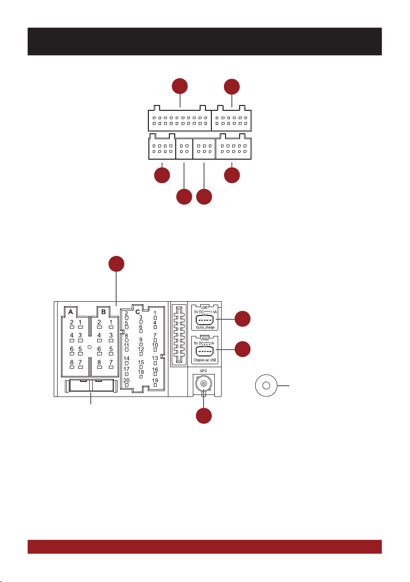
CONNECTION DIAGRAM / Anschlussdiagramm
AUDIO / VIDEO / AV INPUTS
Audio / Video / AV-Eingänge
VAR. SYSTEM CONNECTIONS, E.G. DAB BOX
Div. System-Anschlüsse, z.B. DAB-Box
EXTERNAL BT-MICROPHONE
Externes BT-Mikrofon
ISO CONNECTOR OF THE VEHICLE
I
ISO-Stecker des Fahrzeugs
5
98
AUDIO OUTPUTS 5.1 WITH REMOTE TURN ON
6
Audio-Ausgänge 5.1 mit Einschaltleitung
AUDIO/VIDEO OUTPUTS 1/2
107
Audio/Video-Ausgänge
CAMERA CONNECTIONS
Kamera-Anschlüsse
USB PORT 1 WITH QUICK CHARGE FUNCTION
11
USB-Anschluss 1 mit Schnellladefunktion
USB PORT 2 FOR OEM USB-PORT
11
USB-Anschluss 2 für OEM USB-Anschluss
AM/FM ANTENNA
AM/FM Antenne
FUSE
Gerätesicherung
6
12
GPS ANTENNA
GPS Antenne
Page 7

CONNECTION DIAGRAM / Anschlussdiagramm
ISO ASSIGNMENT
I
A4 =
A5 =
A6 =
A7 =
A8 =
B1 =
B2 =
B3 =
B4 =
B5 =
B6 =
B7 =
B8 =
C1 =
C2 =
C3 =
C7 =
C10 =
C19 =
C20 =
CONSTANT PLUS
ANTENNA
ILLUMINATION
IGNITION PLUS
GROUND
SPEAKER REAR RIGHT +
SPEAKER REAR RIGHT –
SPEAKER FRONT RIGHT +
SPEAKER FRONT RIGHT –
SPEAKER FRONT LEFT +
SPEAKER FRONT LEFT –
SPEAKER REAR LEFT +
SPEAKER REAR LEFT –
KEY1
KEY2
AUX GROUND
AUX SIGNAL R
AUX SIGNAL L
CAN LOW
CAN HIGH
ISO Belegung
A4 =
A5 =
A6 =
A7 =
A8 =
B1 =
B2 =
B3 =
B4 =
B5 =
B6 =
B7 =
B8 =
C1 =
C2 =
C3 =
C7 =
C10 =
C19 =
C20 =
Dauerplus
Antenne
Beleuchtung
Zündungsplus
Masse
Lautsprecher hinten rechts +
Lautsprecher hinten rechts Lautsprecher vorne rechts +
Lautsprecher vorne rechts Lautsprecher vorne links +
Lautsprecher vorne links Lautsprecher hinten links +
Lautsprecher hinten links Key1
Key2
AUX Masse
AUX Signal R
AUX Signal L
Can Low
Can High
7
Page 8

CONNECTION DIAGRAM / Anschlussdiagramm
ENGLISH
IMPORTANT NOTE: On vehicles with radio preparation and ISO connectors usually a „Plug and Play“ installation is possible. In this
case, it is important that the ESX Naviceiver is connected with the ignition plus (ACC, PIN 7).
ATTENTION: Never use the CANBUS together with ignition plus.
FUSE: In case of a defect, the fuse must be replaced with a fuse of the same value (10A). Eliminate the cause of the short circuit
before replacing the defective fuse.
ASSIGNMENT OF THE ACCESSORY CONNECTORS
Audio / Video / AV Inputs G71-AUD0119
5
Name Connector/Color Function
AV1-L-IN RCA white AV Audio left in AV/TV menu
AV1-R-IN RCA red AV Audio right in AV/TV menu
AV1-V-IN RCA yellow AV Video in AV/TV menu
AV2/TV-L-IN RCA white AV2 Audio left in AV/TV menu
AV2/TV-R-IN RCA red AV2 Audio right in AV/TV menu
AV2/TV-V-IN RCA yellow AV2 Video in AV/TV menu
AV3/AUX1-L-IN RCA white AV3 Audio left in AV/TV menu
AV3/AUX1-R-IN RCA red AV3 Audio right in AV/TV menu
AV3-V-IN/VIDEO RCA yellow AV3 Video in AV/TV menu
+12V OUT yellow 12V Output
Power supply for external devices such as DVB-T tuners.
Maximum current consumption 500 mA.
GND plack Ground wire to +12V OUT
TV-CONT-OUT brown Control cable for special ESX devices, please do not use.
BRAKE IN pink Connect to the parking brake signal to the device.
The cable provides ground when the parking brake is operated.
Please do not use if the CANBUS is used, CANBUS has always priority.
Audio – Outputs 5.1 with Remote Turn On G71-MNV0010
6
Name Connector/Color Function
FL-OUT RCA white Pre-amplifier output front left
FR-OUT RCA red Pre-amplifier output front right
RL-OUT RCA white Pre-amplifier output rear left
RR-OUT RCA red Pre-amplifier output rear right
SUBWOOFER-OUT RCA brown Pre-amplifier output Subwoofer (Mono)
CENTER-OUT RCA yellow Pre-amplifier output Center (Mono)
AMP-CONT-OUT green Remote Turn On output
12V output to turn on an external amplifier.
Maximum current consumption 500 mA.
Various System Connections G71-WHE0063
7
Name Connector/Color Function
Uart/+5V OUT black Reserved, please do not use!
SWC1IN red-white For an analog steering wheel signal. Please do not use!
SWC2IN green-white For an analog steering wheel signal. Please do not use!
ILL IN orange Illumination signal „ILL“ input. Same function as ILL on the ISO plug.
ANT-POWER OUT yellow 12V output for FM antenna amplifiers. Attention! The power supply is only active
while the FM function of the device is activated. Max. Current consumption 100 mA.
8
Page 9

CONNECTION DIAGRAM / Anschlussdiagramm
Camera connections G71-CCD0037
9
Name Connector/Color Function
CCD-CVBS-IN RCA yellow Video signal input from the rear camera
FRONT-CCD-IN RCA yellow Video signal input from the front camera
REVERSE IN blue Reverse gear signal input. Please don‘t use when vehicle‘s CANBUS is operated.
If CAN signal is not present, the reverse signal (12V, for example the reversing
light) can be connected here. The ESX device switches to the „CCD CVBS IN“
input as soon as „REVERSE IN“ is supplied with 12V and „CCD-Camera“
checkbox in the option menu under „DISPLAY“ is activated.
CCD-POWER OUT yellow 12V power supply output for an aftermarket rear view camera with max.
100mA. 12V will be supplied, as soon as „REVERSE-IN“ is supplied with 12V.
FRONT CCD-POWER OUT red 12V power supply output for an aftermarket rear view camera with max.
500mA. 12V will be supplied, as soon as the ESX device is turned on.
Make sure that your camera is suitable for continuous operation.
GND black Ground terminal of the power supply of an optional camera (front and rear).
Connect the reverse signal (12V when reverse gear is engaged, for example, also by reversing light) of the vehicle to „REVERSE“ (blue
cable). The „GND“ and „CCD POWER OUT“ cables must not be connected mandatory, but can be used as a power supply for the camera.
Now activate the „CCD-Camera“ checkbox under APPS -> OPTIONS -> DISPLAY at the ESX device.
Operation note:
- Special feature: Push the right rotary controller to display the rear view cam, even when the reverse gear is not engaged.
- When the reverse gear is engaged, the device does not allow any other operation, all the buttons and controllers except
volume controller are blocked for security reasons. If the device is switched off and the reverse gear is engaged, the device
does not even turn on.
Installation note with original OEM camera for type 290 Model: If the CANBUS cable set „VNA-DUC-CAN-SET“ (See page 3) is used,
only the yellow RCA plug „CCD CVBS IN“ must be connected. All other signals are taken over by the CANBUS.
FRONT VIEW CAMERA
Connect the camera via RCA to the yellow RCA connector „FRONT CCD IN“.
Switch to „Camera“ or „Front Camera“ in the menu „AV/TV“ to display your camera view.
Audio/Video Outputs G71-MNV0009
10
Name Connector/Color
AUDIO L OUT/ZONE-1 RCA white
AUDIO R OUT/ZONE-1 RCA red
V-OUT1/ZONE-1 RCA yellow
AUDIO L OUT/ZONE-2 RCA white
AUDIO R OUT/ZONE-2 RCA red
V-OUT2/ZONE-2 RCA yellow
IMPORTANT NOTE: Connection for e.g. headrest monitors or other devices such like TVs in the rear. The audio/video outputs is always
the same signal to which will be played just on the ESX device. An independent input source selection is not possible.
9
Page 10

INSTALLATION NOTES / Installationshinweise
DEUTSCH
WICHTIGER HINWEIS: Bei Fahrzeugen mit Radiovorbereitung und ISO Steckern ist in der Regel eine „Plug and Play“-Installation
möglich. In diesem Fall ist es wichtig, dass der ESX Naviceiver mit Zündungsplus (ACC, PIN 7) angeschlossen wird.
ACHTUNG: Verwenden Sie niemals den CANBUS zusammen mit Zündungsplus.
GERÄTESICHERUNG: Im Falle eines Defektes darf die Sicherung nur mit einer Sicherung des gleichen Wertes erneuert werden (10A).
Beseitigen Sie vor dem Erneuern der defekten Sicherung die Ursache des Kurzschlusses.
BELEGUNG DER ZUBEHÖR-STECKER
Audio / Video / AV Eingänge G71-AUD0119
5
Kabelname Stecker/Farbe Funktion im Gerät
AV1-L-IN RCA weiß AV Audio links im AV/TV Menü
AV1-R-IN RCA rot AV Audio rechts im AV/TV Menü
AV1-V-IN RCA gelb AV Video im AV/TV Menü
AV2/TV-L-IN RCA weiß AV2 Audio links im AV/TV Menü
AV2/TV-R-IN RCA rot AV2 Audio rechts im AV/TV Menü
AV2/TV-V-IN RCA gelb AV2 Video im AV/TV Menü
AV3/AUX1-L-IN RCA weiß AV3 Audio links im AV/TV Menü
AV3/AUX1-R-IN RCA rot AV3 Audio rechts im AV/TV Menü
AV3-V-IN/VIDEO RCA gelb AV3 Video im AV/TV Menü
+12V OUT gelb 12V Ausgang
Spannungsversorgung für externe Geräte wie z.B. DVB-T Tuner.
Maximale Stromaufnahme 500 mA.
GND schwarz Masseleitung zu +12V OUT
TV-CONT-OUT braun Steuerleitung für spez. ESX Geräte. Bitte nicht verwenden!
BRAKE IN rosa Schließen Sie hier das Handbremssignal an das Gerät an.
Das Kabel führt Masse, wenn die Handbremse betätigt ist.
Bitte nicht verwenden falls CANBUS verwendet, CANBUS hat Priorität.
Audio – Ausgänge 5.1 mit Einschaltleitung G71-MNV0010
6
Kabelname Stecker/Farbe Funktion im Gerät
FL-OUT RCA weiß Vorverstärkerausgang Vorne Links
FR-OUT RCA rot Vorverstärkerausgang Vorne Rechts
RL-OUT RCA weiß Vorverstärkerausgang Hinten Links
RR-OUT RCA rot Vorverstärkerausgang Hinten Rechts
SUBWOOFER-OUT RCA braun Vorverstärkerausgang Subwoofer (Mono)
CENTER-OUT RCA gelb Vorverstärkerausgang Center (Mono)
AMP-CONT-OUT grün Remote Ausgang
12V Ausgangsspannung zum Einschalten eines externen Verstärkers.
Maximale Stromaufnahme 500 mA.
Div. System-Anschlüsse G71-WHE0063
7
Kabelname Stecker/Farbe Funktion im Gerät
Uart/+5V OUT schwarzer Stecker Reserviert. Bitte nicht verwenden!
SWC1IN rot-weiß Für analoges Lenkradsignal. Bitte nicht verwenden!
SWC2IN grün-weiß Für analoges Lenkradsignal. Bitte nicht verwenden!
ILL IN orange Lichtsignal „ILL“ Eingang. Gleiche Funktion wie ILL am ISO Stecker.
ANT-POWER OUT gelb 12V Ausgang für UKW-Antennenverstärker. Achtung! Spannung wird nur bei
aktiver UKW-Funktion des Geräts ausgegeben. Max. Stromaufnahme 100 mA.
10
Page 11

INSTALLATION NOTES / Installationshinweise
Kamera Anschlüsse G71-CCD0037
9
Kabelname Stecker/Farbe Funktion im Gerät
CCD-CVBS-IN RCA gelb Videosignal-Eingang der Rückfahrkamera
FRONT-CCD-IN RCA gelb Videosignal-Eingang der Frontkamera
REVERSE IN blau Rückwärtsgangsignal-Eingang. Bitte nicht verwenden, wenn Fahrzeug mit
CANBUS betrieben wird. Wenn CAN Signal nicht vorhanden ist, kann hier das
Rückwärtsgangsignal (12V, z.B. Rückfahrscheinwerfer) angeschlossen werden.
Das ESX Radio schaltet auf den „CCD-CVBS-IN“ Eingang um, sobald an
„REVERSE IN“ 12V anliegen und „CCD-Kamera“ im Menü „Optionen“ unter
„Bildschirm“ eingeschaltet ist.
CCD-POWER OUT gelb 12V Ausgang für Stromversorgung einer Nachrüst-Rückfahrkamera mit
max. 100mA. 12V werden ausgegeben, sobald an „REVERSE IN“ 12V anliegen.
FRONT CCD-POWER OUT rot 12V Ausgang für Stromversorgung einer Nachrüst-Frontkamera, max. 500mA.
12V werden ausgegeben, sobald das ESX Gerät in Betrieb ist. Stellen Sie sicher,
dass Ihre Kamera für den Dauerbetrieb geeignet ist.
GND schwarz Masseanschluss der Stromversorgung einer optionalen Kamera (Front u. Rear).
Schließen Sie das Rückwärtsgang-Signal (12V sobald der Rückwärtsgang eingelegt ist, z.B. auch vom Rückfahrscheinwerfer) des Fahrzeuges an „REVERSE“ (blaues Kabel) an. Die „GND“ sowie „CCD-POWER OUT“ Kabel müssen nicht zwingend angeschlossen werden,
können aber als Stromversorgung für die Kamera verwendet werden.
Aktivieren sie abschließend den Punkt „CCD-Kamera“ unter APPS -> OPTIONEN-> „Bildschirm“.
Bedienhinweis:
- Als besondere Funktion kann die Rückfahrkamera bei diesem Gerät jederzeit durch Drücken des rechten Drehreglers aktiviert
werden, auch wenn der Rückwärtsgang nicht eingelegt ist.
- Ist der Rückwärtsgang eingelegt, lässt das Gerät keine andere Bedienung zu, alle Tasten (außer Lautstärkeregelung)
werden aus Sicherheitsgründen blockiert. Ist das Gerät ausgeschaltet und der Rückwärtsgang wird eingelegt, lässt sich deshalb das
Gerät auch nicht einschalten.
Installationshinweis mit originaler OEM Kamera am Modell Typ 290: Wenn das CANBUS Kabel „VNA-DUC-CAN-SET“ (Siehe Seite
3) verwendet wird, muss lediglich der gelbe RCA Stecker an „CCD-CVBS-IN“ angeschlossen werden. Alle weiteren Signale werden vom
Canbus übernommen.
FRONTKAMERA
Schließen sie das Videosignal Ihrer Kamera per Cinch an die gelbe Cinchbuchse „FRONT CCD IN“an.
Schalten Sie im Menü „AV/TV“ mit dem Button „“Kamera“ bzw „Front Kamera“ auf die Kamera um.
Audio/Video-Ausgänge G71-MNV0009
10
Kabelname Stecker/Kabelfarbe
AUDIO L OUT/ZONE-1 RCA weiß
AUDIO R OUT/ZONE-1 RCA rot
V-OUT1/ZONE-1 RCA gelb
AUDIO L OUT/ZONE-2 RCA weiß
AUDIO R OUT/ZONE-2 RCA rot
V-OUT2/ZONE-2 RCA gelb
WICHTIGER HINWEIS: Anschluss für z.B. Kopfstützen-Monitore im Fond bzw. weitere Wiedergabegeräte wie z.B.TV-Geräte. An den
Audio/Videoausgängen liegt immer das gleiche Signal an welches gerade am ESX-Gerät abgespielt wird. Eine unabhängige Quellenwahl ist nicht möglich.
11
Page 12

INSTALLATION NOTES / Installationshinweise
Installation hints:
Einbautipps:
12
11 13
Transportation lock:
Remove both transportation locks on top of the device before you start the
installation.
Transportsicherung:
Entfernen Sie beide Transportsicherungen auf der Oberseite des Geräts, bevor
Sie mit der Installation beginnen.
GPS antenna:
The GPS (12) antenna must be mounted horizontally in front on the dashboard
(ensure a clear view to the sky). A metalized windscreen allows no reception. If a factory GPS antenna with the same connector type (Fakra) is already
available, it can be used. Then the installation of the included GPS antenna is
not necessary.
GPS Antenne:
Die GPS Antenne (12) muss waagerecht, nach Möglichkeit vorne auf dem Armaturenbrett montiert werden (auf freie Sicht zum Himmel achten). Bei einer
metallbedampften Scheibe ist kein Empfang möglich. Falls eine werksseitige
GPS-Antenne mit dem denselben Steckertyp (Fakra) bereits vorhanden ist,
kann diese verwendet werden. Die Installation der beiliegenden GPS Antenne
entfällt.
USB Connectors:
Route the cables (11) to a desired location, such as the glove box. If necessary,
you must drill openings. One of the USB ports is needed for the TMC antenna
(13).
USB-Anschlüsse:
Verlegen Sie die Kabel (11) an den gewünschten Einbauort, wie z.B. im Handschuhfach. Gegebenenfalls müssen dafür Öffnungen gebohrt werden.
Einer der USB Anschlüsse wird für die TMC Antenne (13) benötigt.
12
BT-Microphone:
8
The device has an internal microphone. For an even better transmission quality
you can mount the supplied microphone (8) at a suitable point such as at the
A-pillar (driver‘s side) or on the roof lining at the interior lamp. Avoid laying the
cable over the steering column. In general, the cable should be long enough to
reach a desired mounting point at the A-pillar (driver‘s side) while laying the
cable over the the passenger‘s side. A possibly existing factory microphone is
not compatible with the ESX device.
BT-Mikrofon:
Das Gerät besitzt ein internes Mikrofon. Für eine noch bessere Übertragungsqualität können Sie das beiliegende Mikrofon (8) an einem geeigneten Montagepunkt wie z.B. an der A-Säule (Fahrerseite) oder am Dachhimmel bei der
Innenraumleuchte anbringen. Vermeiden Sie das Verlegen des Kabels über
die Lenksäule. In der Regel sollte das Kabel lang genug sein, um die A-Säule
(Fahrerseite) über die Beifahrerseite zu erreichen. Ein evtl. werksseitig vorhandenes Mikrofon ist nicht kompatibel mit dem ESX Gerät.
Page 13

13
14
INSTALLATION NOTES / Installationshinweise
Handbrake connection:
5
The handbrake signal needs to be connected with the included cable (5, BRAKE
IN). The signal must be connected to ground with the handbrake closed. Please contact for a correct and safe installation your automotive service center!
Accordance to legal regulations the device must only playback a DVD or video
may on the main screen only with the handbrake closed. Therefore the cable
must be permanently connected to ground. To avoid accidents through carelessness, the display is turned of while driving. The video outputs (10) are
not affected.
Note: If you have connected the CANBUS, the brake signal must not be connected.
Handbremsen-Anschluss:
Das Handbremssignal muss an das beiliegende Kabel (5, BRAKE IN) angeschlossen werden. Das Signal muss bei angezogener Handbremse auf
Masse liegen. Bitte wenden Sie sich für eine korrekte und gefahrlose Installation an Ihre KFZ-Fachwerkstatt! Gemäß den gesetzlichen Bestimmungen
darf das Gerät eine DVD bzw. Videowiedergabe auf dem Hauptbildschirm
nur bei angezogener Handbremse wiedergeben. Das Anschlusskabel darf
deshalb nicht dauerhaft auf Masse angeschlossen werden. Während der
Fahrt wird der Bildschirm zur Vermeidung von Unfällen durch Unachtsamkeit dunkel geschaltet. Die Videoausgänge (10) sind hiervon nicht betroffen.
Hinweis: Sollten Sie den CANBUS angeschlossen haben, muss das Handbremssignal nicht angeschlossen werden.
TMC cable antenna:
Connect the enclosed TMC antenna (13) with the USB port and then lay the antenna to a suitable location on the windscreen. For optimal reception it should
be fastened to the windscreen by using the suction cups, A hidden installation
e.g. under the A-pillar or the dashboard is also possible. This is only necessary if the included Y-splitter VNA-TMC-Y2 (14) is not used, as now the vehicle
antenna is used.
Installation tip:
By using the kit „VNA-DUC-CAN-SET“ and an existing OEM USB port with the
Y-splitter (14) there is no need to drill a hole.
TMC Kabelantenne:
Schließen Sie die beiliegende TMC Antenne (13) an den USB Anschluss an
und verlegen Sie dann die Wurfantenne an eine geeignete Stelle an der Frontscheibe. Für einen optimalen Empfang kann diese an der Scheibe mithilfe der
Saugnäpfe befestigt werden, auch ein verstecktes Verlegen z.B. unter der ASäule oder unter dem Armaturenbrett ist möglich. Das ist nur nötig, wenn der
mitgelieferte Y-Splitter VNA-TMC-Y2 (14) nicht verwendet wird, da hierbei die
Fahrzeugantenne verwendet wird.
Installationstipp:
Bei Verwendung des Einbaukits „VNA-DUC-CAN-SET“ bei vorhandenem OEM
USB-Anschluss mit dem Y-Splitter (14) muss kein Loch gebohrt werden.
13
Page 14

INSTALLATION EXAMPLE / Einbaubeispiel
FIAT DUCATO III DETHLEFFS (Type 250, 2006 ->)
The following installation examples shows the installation of a ESX Naviceiver
1
2
into a Fiat Ducato III model from Dethleffs. Due to many different variants of the
Fiat Ducato platform, some of the descriptions and instructions in this installation
guide may not be applicable.
Das folgende Einbaubeispiel zeigt die Installation eines ESX Naviceivers in ein Fiat
Ducato III Modell von Dethleffs. Aufgrund der vielen verschiedenen Ausstattungsvarianten der Fiat Ducato-Plattform, könnten einige Beschreibungen und Installationshinweise in dieser Einbauanleitung nicht zutreffend sein.
First, remove the radio and storage compartment in the dashboard. Use suitable
mounting wedges.
Entfernen Sie als erstes das Radio und Ablagefach im Armaturenbrett. Verwenden
Sie dazu geeignete Montagekeile.
14
3
4
5
Pull the radio bracket from the bay.
Ziehen Sie die Radiohalterung aus dem Schacht.
Remove the DIN mounting frame. To do this, loosen the two upper and two lower
screws inside the radio bay.
Entfernen Sie den DIN-Einbaurahmen. Lösen Sie dafür die beiden oberen sowie
die beiden unteren Schrauben im Innern des Radioschachts.
Loosen the DIN mounting frame. Use suitable mounting wedges. The pull the
frame from the bay.
Lösen Sie den DIN-Einbaurahmen. Verwenden Sie dazu geeignete Montagekeile.
Ziehen Sie dann die Halterung aus dem Schacht.
Page 15

INSTALLATION EXAMPLE / Einbaubeispiel
FIAT DUCATO III DETHLEFFS (Type 250, 2006 ->)
6
7
8
9
Remove the ridges inside the radio bay on both sides.
Entfernen Sie die Stege im Innern des Radioschachts auf beiden Seiten.
The upper storage compartment above the radio bay is perfect for the GPS antenna (12) installation.
Das obere Ablagefach über dem Radioschacht eignet sich perfekt, um dort die
GPS-Antenne (12) zu installieren.
Remove the lower glove box. Loosen the three screws as marked on the image.
Entfernen Sie das untere Handschuhfach. Lösen Sie die drei Schrauben wie
auf dem Bild markiert.
Loosen the fourth screw on the right.
Lösen Sie die vierte Schraube rechts.
10
Remove the cover above the right wheel well. Loosen altogether three screws. In
the picture two of them are marked.
Entfernen Sie die Abdeckung über dem rechten Radkasten. Lösen Sie insgesamt drei Schrauben. Auf dem Bild sind zwei davon markiert.
15
Page 16

11
INSTALLATION EXAMPLE / Einbaubeispiel
FIAT DUCATO III DETHLEFFS (Type 250, 2006 ->)
Open the upper glove box and unmount it on the side.
Öffnen Sie das obere Handschuhfach und hängen Sie es seitlich aus.
12
13
14
15
Loosen the screw on the left.
Lösen Sie die Schraube links.
Pull the glove box.
Ziehen Sie das Handschuhfach heraus.
Now drill a hole (approx. 20 mm in diameter) for the USB cable on the rear of
the unmounted glove box. For this, use a suitable plastic drill.
Bohren Sie nun eine Öffnung (ca. Ø 20 mm) für das USB-Kabel auf der Rückseite des ausgehängten Handschuhfachs. Verwenden Sie dafür einen geeigneten Kunststoffbohrer.
Install now the supplied ESX device holder into the radio bay. For this, use the
included screws. Now lay the cable of the new ESX device (See page 4-5) inside
the vehicle from the bay to the desired installation location.
Installieren Sie die im Lieferumfang enthaltene ESX-Einbauhalterung im Radioschacht. Verwenden Sie dafür die beiliegenden Schrauben. Verlegen Sie nun die
Anschlusskabel des neuen ESX Geräts (Siehe S. 4-5) im Fahrzeug vom Einbauschacht zum gewünschten Einbauort.
16
Page 17

16
17
18
INSTALLATION EXAMPLE / Einbaubeispiel
FIAT DUCATO III DETHLEFFS (Type 250, 2006 ->)
Now connect all connections according (Refer to page 4-5) with the sockets on
the new ESX device. Plug in also the ISO power- and speaker connector and the
antenna connector.
Note: If the vehicle has an analog steering wheel remote control, use to adapt the accessory cable (15). Refer for the programming p.40 of the owner‘s
manual.
Schließen Sie jetzt alle Kabelstecker entsprechend (Siehe S. 4-5) am neuen
ESX-Gerät an. Schließen Sie ebenfalls den ISO Strom- und Lautsprecherstecker sowie den Antennenstecker an.
Hinweis: Hat das Fahrzeug eine analoge Lenkradfernbedienung, verwenden
Sie zur Adaption das Zubehörkabel (15). Beachten Sie zur Programmierung
S.40 der Bedienungsanleitung.
Slide the ESX device carefully into the radio bay. Before you complete the installation of the new ESX device, check its function. Please note that it may take up to
15 minutes, until a GPS signal can be received (in the open).
Schieben Sie das ESX-Gerät vorsichtig in den Radioschacht. Prüfen Sie vor dem
Zusammenbau das neue ESX-Gerät auf seine Funktion. Bitte beachten Sie, dass
es bis zu 15 Minuten dauern kann, bis ein GPS Signal (unter freiem Himmel) empfangen werden kann.
After the successful check of the functions, re-assemble the new device in the
reverse order (steps no. 8 -13).
Führen Sie nach erfolgreicher Prüfung der Funktionen dann den Zusammenbau
(Nr. 8 -13) in umgekehrter Reihenfolge durch.
17
Page 18

INSTALLATION EXAMPLE / Einbaubeispiel
CITROEN JUMPER III (Type 290, 2015 ->)
Installation example with original factory radio
Einbaubeispiel mit Original-Radio ab Werk
Remove the original radio with a suitable unlocking tool.
1
2
3
Entfernen Sie das Original-Radio mit geeignetem Entriegelungswerkzeug.
Pull out the original radio and remove all connecting cables.
Ziehen Sie das Original-Radio vorsichtig heraus und entfernen Sie alle Anschlusskabel.
Remove the original radio bay by unscrewing the four screws (Torx 25) as shown
left.
Entfernen Sie den Einbauschacht des Original-Radios indem Sie die vier links
gezeigten Schrauben (Torx 25) lösen.
18
Remove the document holder by unscrewing the two screws (Torx 25) as shown
4
5
left. Pull out the holder upwards.
Entfernen Sie den Dokumentenhalter indem Sie die zwei links gezeigten
Schrauben (Torx 25) lösen. Entnehmen Sie den Halter indem Sie ihn nach
oben herausnehmen.
Remove the two vent inserts left and right with a suitable plastic tool. These are
just clipped (see markings).
Note: Eventually, you can only remove the plastic cover first. This is also only
clipped on the ventilation grille insert.
Entfernen Sie die beiden Lüftungseinsätze rechts und links mit geeignetem
Kunststoffwerkzeug. Diese sind nur geclipst (Siehe Markierungen).
Hinweis: Evtl. lässt sich zuerst nur die Plastikblende entfernen. Diese ist
ebenfalls nur auf den Lüftungsgittereinsatz eingeclipst.
Page 19

INSTALLATION EXAMPLE / Einbaubeispiel
CITROEN JUMPER III (Type 290, 2015 ->)
Installation example with original factory radio
Einbaubeispiel mit Original-Radio ab Werk
Note: The adjusting mechanism of vent inserts are greased!
6
7
8
Hinweis: Die Verstellmechanik der Lüftungseinsätze sind gefettet!
Loosen the shift boot trim. This is also just clipped, use a plastic tool and loosen
it from the top.
Lösen Sie die Schaltsackverkleidung. Diese ist ebenfalls nur geclipst, Benutzen Sie ein Kunststoffwerkzeug und lösen Sie diese von oben.
Remove the cup holder on the right inner screw (Torx 25).
Entfernen Sie im Becherhalter rechts die innenliegende Schraube (Torx 25).
10
Remove the cover of the hazard switch, cigarette lighter, including cup holders
9
unit from below with a suitable plastic tool. Then, remove all cables on the
back and put the panel aside.
Entfernen Sie die Verkleidung des Warnblinkschalters, Zigarettenanzünders
samt Becherhalter-Einheit von unten mit geeignetem Kunststoffwerkzeug.
Entfernen Sie dann die Anschlusskabel hinten und legen Sie die Verkleidung
beiseite.
Remove the two marked screws (Torx 25, the right outside and the second
from the left).
Entfernen Sie die beiden markierten Schrauben (Torx 25, rechts ganz außen
sowie die zweite von links).
19
Page 20

11
12
13
INSTALLATION EXAMPLE / Einbaubeispiel
CITROEN JUMPER III (Type 290, 2015 ->)
Installation example with original factory radio
Einbaubeispiel mit Original-Radio ab Werk
Remove the two marked screws (Torx 25) at the top, where the document
holder was.
Entfernen Sie die beiden markierten Schrauben (Torx 25) ganz oben, wo sich
der Dokumentenhalter befand.
Remove the two marked screws (Torx 25) either side of the radio bay.
Entfernen Sie die beiden markierten Schrauben (Torx 25) rechts und links des
Radioschachts.
Entfernen Sie die große Mittelkonsolenblende. Diese ist nur noch ganz oben an
zwei Punkten geclipst.
Entfernen Sie die große Mittelkonsolenblende. Diese ist nur noch ganz oben
an zwei Punkten geclipst.
20
14
15
From here the installation of ESX device starts. Start from here if your car is
equipped with the factory radio preparation.
Ab hier beginnt der Einbau des ESX-Geräts. Beginnen Sie ab hier, falls Ihr
Fahrzeug nur mit der Radiovorbereitung ab Werk ausgestattet ist.
Take the original FIAT center console panel (See page 3) to hand. Remove the
two ridges in the radio slot with a saw.
Nehmen Sie die originale FIAT Mittelkonsolenblende (Siehe Seite 3) zur Hand.
Entfernen Sie die beiden Stege im Radioschacht mit einer Säge.
Page 21

16
17
18
INSTALLATION EXAMPLE / Einbaubeispiel
CITROEN JUMPER III (Type 290, 2015 ->)
Installation example with original factory radio
Einbaubeispiel mit Original-Radio ab Werk
Insert the new the original FIAT center console cover into the dashboard. Make
sure that the upper clips snap into place. Set in the two screws at the top
(below the document holder), the two screws in the ventilation openings and
the two screws at the bottom under the air conditioning again (See steps 10,
11 and 12).
Setzen Sie die neue originale Fiat Mittelkonsolenblende in das Armaturenbrett
ein. Achten Sie darauf, dass die oberen Clipse einrasten. Setzen Sie die zwei
Schrauben oben (Unter dem Dokumentenhalter), die zwei Schrauben in den
Lüftungskanälen sowie die beiden Schrauben ganz unten unter der Klimaregelung wieder ein (Siehe Schritte 10, 11 und 12).
Now lay all necessary cables, for example the external microphone, USB, GPS,
to the desired location. Now you can also lay additional cables such as for
the rear view camera to the radio bay. Please refer to the following steps of
the installation.
Verlegen Sie nun die benötigten Kabel, für z.B. externes Mikrofon, USB, GPS,
zum gewünschten Einbauort. Zudem können nun auch weitere Verkabelungen
wie z.B. für die Rückfahrkamera zum Radioschacht verlegt werden. Berücksichtigen Sie zudem die nachfolgenden Schritte der Montage.
Now set in the removed document holder (Step 4) .
Setzen Sie nun den unter Schritt 4 entfernten Dokumentenhalter wieder ein.
19
20
Now install the two ESX installation holders (See page 5) and fasten both with
the four original screws (Torx 25) to the original mounting points.
Nehmen Sie die beiden ESX Einbauhalter (Siehe Seite 5) zur Hand und befestigen Sie beide komplett mit den vier Original-Schrauben (Torx 25) an den
ursprünglichen Befestigungspunkten.
Connect the optional VNA-DUC-CAN-SET cable (See page 3) to the original
connector of the vehicle. Also, connect the Antenna and the USB adaptor to
the OEM connectors.
Schließen Sie das optionale VNA-DUC-CAN-SET Kabel (Siehe Seite 3) an den
Original-Stecker des Fahrzeugs an. Schließen Sie zudem den Antennen- sowie
den USB Adapter an die Originalkabel an.
21
Page 22

21
22
INSTALLATION EXAMPLE / Einbaubeispiel
CITROEN JUMPER III (Type 290, 2015 ->)
Installation example with original factory radio
Einbaubeispiel mit Original-Radio ab Werk
Now connect all cables and connectors of the ESX device. Slide in the ESX
device carefully approx. 4/5ths into the radio bay and perform a functional
test of all functions.
Schließen Sie jetzt alle Kabel und Stecker an das ESX Gerät an. Schieben Sie
das ESX Gerät vorsichtig etwa 4/5tel in den Radioschacht und führen Sie eine
Funktionsprüfung aller Funktionen durch.
If all functions are ensured, push in the ESX device until it stops and clicks in. Then
perform the re-assembly (Step 5 - 14) in reverse order.
Wenn alle Funktionen gewährleistet sind, drücken Sie das ESX Gerät bis zum
Anschlag e in bis es einrastet und führen dann den Zusammenbau (Schritt 5 - 14)
in umgekehrter Reihenfolge durch.
22
Page 23

INSTALLATION EXAMPLE / Einbaubeispiel
FIAT DUCATO IV (Type 290, 2015 ->)
Installation example only with radio preparation from the factory
Einbaubeispiel nur mit Radiovorbereitung ab Werk
Even when there is no OEM radio, the CANBUS of the model type 290 can be
connected to the ESX device to display the driving data. It is also possible
to use the original steering wheel remote control and to change the vehicle
settings in the „System“ menu (Apps -> System -> Option).
Auch bei nicht vorhandenem OEM Radio kann beim Modell Typ 290 der CANBUS des Fahrzeugs an das ESX Gerät angeschlossen werden, um die Fahrdaten anzeigen zu lassen. Ebenso ist es möglich, hierdurch die originale
Lenkradfernbedienung zu benutzen sowie die Fahrzeugeinstellungen im Menü
„System“ (Apps -> Optionen -> System) zu verändern.
Connect therefore the following adapter (15).
Schließen Sie hierfür folgenden Adapter (15) an.
G71-WHE0078
ADAPTOR CANBUS / STEERING WHEEL CONTROL
Adapter CANBUS / Lenkradfernsteuerung
First refer to the installation instructions on page 13 #1 to 16 #16 and then continue here with #1
to #7. Finish the installation as described on page 16 #17.
Beachten Sie zunächst die Installationshinweise auf den Seiten 13 #1 - 16 #16 und fahren dann
hier mit #1 - #7 fort. Beenden sie die Installation wie ab Seite 16 #17 beschrieben.
1
2
Remove the cover of the fuse box (2 x Phillips PH2).
Entfernen Sie die Abdeckung des Sicherungskastens (2 x Kreutzschlitz PH2).
Locate the diagnostic connector, bottom left, labeled with MOD.
Lokalisieren Sie den Diagnosestecker links unten, beschriftet mit MOD.
23
Page 24

INSTALLATION EXAMPLE / Einbaubeispiel
FIAT DUCATO IV (Type 290, 2015 ->)
Installation example only with radio preparation from the factory
Einbaubeispiel nur mit Radiovorbereitung ab Werk
Remove the cover and unlock the connector on the left side by pressing the
3
4
5
nose and push it out to the rear.
Entfernen Sie die Abdeckung und entriegeln Sie den Stecker auf der linken
Seite durch drücken der Nase und schieben Sie ihn nach hinten raus.
The blue and white cables containing the CAN BUS. Take, before connecting
the ESX device, the adapter (15) at hand and lay the two long cable ends CANH
and CANL from the radio bay to the fuse box. WARNING: Make sure that the
cable has no contact with the steering column!
Das blaue und weiße Kabel enthält den CANBUS. Nehmen Sie, bevor Sie das
ESX Gerät anschließen, den Adapter (15) zur Hand und verlegen dessen beiden
langen Kabelenden CANH und CANL vom Radioschacht zum Sicherungskasten. ACHTUNG: Achten Sie darauf, dass das Kabel keinen Kontakt zur Lenksäule hat!
Now connect the cables as following:
CANH to the blue cable
CANL to the weiße cable
Schließen Sie die Kabel an den Stecker wie folgt an:
CANH an das blaue Kabel
CANL an das weiße Kabel
24
Set in the diagnostic connector MOD again, make sure that it fully locks into
6
7
place.
Bauen Sie den Diagnosestecker MOD wieder ein, stellen Sie sicher dass dieser
wieder vollständig einrastet.
Connect the three-part mini-ISO plug of the adapter (15) directly with the
ESX device.
Schließen Sie den dreiteiligen Mini-ISO Stecker des Adapters (15) direkt an
das ESX Gerät an.
Page 25

NOTES / Notizen
25
Page 26

NOTES / Notizen
26
Page 27

NOTES / Notizen
27
Page 28

D E S I G N
ESX Car Media Systems · Audio Design GmbH
Am Breilingsweg 3 · D-76709 Kronau/Germany
Tel. +49 7253 - 9465-0 · Fax +49 7253 - 946510
www.esxnavi.de - www.audiodesign.de
©2017 All Rights Reserved
 Loading...