

Page 1
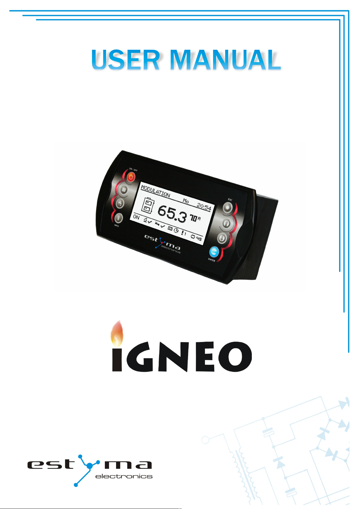
BOILER CONTROLLER
COMPACT
Page 2

page 2
PL20110629
Page 3

Index
Index
1 General information 5
1.1 Introduction 5
1.2 Features 5
1.3 Safety precautions 7
1.4 Disposal of old equipment 8
2 Connecting to the system 9
2.1 General requirements 9
2.2 Location 9
2.3 Assembly 10
2.4 Connecting 11
2.4.1 Direct connection of devices............................................................................. 11
2.4.2 Connecting using burner wire........................................................................... 13
3 Overview of the basic functions 15
3.1 Control panel 15
3.1.1 The status LED............................................................................................... 15
3.1.2 Buttons......................................................................................................... 16
3.1.3 Graphic display ............................................................................................. 17
3.2 Statuses of furnace 17
4 Handling 18
4.1 Navigation in the menu 18
4.2 Starting regulator - ON 18
4.3 Switching off the regulator - OFF 18
4.4 Time scheduling 19
4.5 Service password 20
5 Simple menu 21
5.1 Simple menu screens 21
6 Main menu 23
6.1 Heating 24
6.1.1 Selection of circuit.......................................................................................... 24
6.1.2 State............................................................................................................ 24
6.1.3 Settings........................................................................................................ 25
6.1.4 Time program................................................................................................ 25
6.1.5 Service......................................................................................................... 26
6.2 Hot water 28
estyma electronics
www.estyma.pl
page 3
PL20110629
Page 4

Index
6.2.1 Selection of circuit.......................................................................................... 28
6.2.2 State............................................................................................................ 28
6.2.3 Settings........................................................................................................ 29
6.2.4 Time program................................................................................................ 29
6.2.5 Service......................................................................................................... 30
6.3 Buffer 31
6.3.1 State............................................................................................................ 31
6.3.2 Settings........................................................................................................ 31
6.3.3 Time program................................................................................................ 32
6.3.4 Service......................................................................................................... 32
6.4 Boiler 33
6.4.1 State............................................................................................................ 33
6.4.2 Settings........................................................................................................ 33
6.4.3 Service......................................................................................................... 34
6.5 Settings 35
6.5.1 Date and time................................................................................................ 35
6.5.2 Language...................................................................................................... 35
6.5.3 General settings............................................................................................. 35
6.5.4 Service......................................................................................................... 35
6.6 Burner 38
6.6.1 State............................................................................................................ 38
6.6.2 Settings........................................................................................................ 38
6.6.3 Service......................................................................................................... 39
6.7 Alarms 40
6.7.1 Alarm codes.................................................................................................. 40
6.8 Solar 46
6.8.1 State............................................................................................................ 46
6.8.2 Settings........................................................................................................ 46
6.8.3 Service......................................................................................................... 47
6.9 Info 47
7 Expansion of the system - CAN bus 48
7.1 Sonda Lambda 51
7.2 Solars 53
8 Specification 55
page 4
PL20110629
Page 5

1 General information
1 General information
Thank you for choosing our product and congratulations on a good decision. We will be
grateful for comments concerning the unit’s performance.
ESTYMA electronics
Team
1.1 Introduction
Controller IGNEO Compact is a modern microprocessor system, which controls not only
the boiler, but also the central heating system and domestic hot water.
The device controls the burning process by providing the appropriate amount of air and
fuel. By using solid state relays the power of blower is regulated smoothly.
Thanks to the advanced algorithm and possibility to regulation of many parameters, the
system can be very flexible to adapt to the needs of the heating system.
1.2 Features
Graphic display – thanks to a large graphic display FSTN handling device is intuitive.
Large fonts and icon - to improve ease of handling equipment for elderly people.
Two types of menus - menus simple and sophisticated. During the daily operation of the
device can support is easily accessible from the simple menu.
Info button - the controller is equipped with the function of intelligent assistance. Each
parameter is described, calling the description is done by pushing the info button.
estyma electronics
www.estyma.pl
page 5
PL20110629
Page 6

1 General information
The modular construction of the CAN - using industrial CAN bus data exchange (mainly
used in the demanding automotive industry), it is possible to expansion of the system. The
maximum extension is 16 heating circuits, two circuits of hot water, energy buffers and solars.
Buffer - controlling the heating system in combination with heat storage reservoir.
Solars - the controller controls the solar system.
Powerful modern 32-bit ARM processor (ARM family is widely used in mobile phones) -
enables advanced controlling algorithm device Fuzzy Logic II generation.
The history of alarms and errors - the controller keeps a history of the last 20 errors and
alarms with a description, date of creation and the date of confirmation.
Clock with calendar - the clock allows to program in a weekly cycle required temperatures in
the rooms and hot water which contributes to a reduction in expenditure on fuel.
Statistics - in memory controller stores statistical data of the system, so it is possible to
observe the work and reduce fuel consumption. For example, monitoring temperature and
power boiler burner. Feeder operating time of the fuel.
Beep sound alarm - built-in piezoelectric loudspeaker signals the occurrence of an alarm in
the boiler, which increases operational safety of the device.
Resetting - function allows you to restore factory settings of the controller.
page 6
PL20110629
Page 7

1 General information
1.3 Safety precautions
Warning – risk of electric shock!
• Read this operation manual carefully and thoroughly before using the unit.
• Keep this operation manual and refer to it whenever you work with this unit in the
future.
• Apply all the rules and heed all the warnings included in the unit operation manual.
• Make sure that the unit is not damaged. In case of any doubts, do not use the unit and
contact the supplier.
• In case of any doubts concerning the safe operation of the unit, contact the supplier.
• Pay special attention to all warning signs on the unit casing and its package.
• Use the unit as intended.
• The unit is not a toy. Do not allow children to play with it.
• Under no circumstances children should be allowed to play with any parts of the
package of the unit.
• Access to small parts such as clamping screws or bolts should be secured against
children. Such elements may be delivered with the unit and may result in choking when
swallowed by a child.
• Do not make any mechanical or electrical changes to the unit. Such changes may cause
the unit to malfunction and fail to meet the relevant standards, leading to an adverse
impact on the performance of the unit.
• Do not insert any objects into the unit through openings (e.g. ventilation grills), as this
may cause short circuiting, electric shock, fire or damage to the unit.
• Do not allow water, humidity or dust to enter the unit, as this may cause short
circuiting, electric shock, fire or damage to the unit.
• Provide adequate ventilation of the unit, do not cover or block the ventilation grills, and
ensure that there is free flow of air around the unit.
• The unit should be installed indoors unless it is adapted for outdoor operation.
• Do not expose the unit to mechanical impacts and vibrations.
• When connecting the unit to power supply, make sure that the parameters of the supply
network are within the unit’s operating range.
• All electrical connections must be as shown in the electrical assembly drawings and
must comply with national and/or local regulations concerning electrical connections.
estyma electronics
www.estyma.pl
page 7
PL20110629
Page 8

1 General information
• This unit contains no parts that may be replaced by the user. All maintenance work
except for cleaning, fuse replacement (when the unit is de-energized), and function
setting, should be performed by an authorized service provider.
• Before doing any maintenance work, you must cut off the power supply to the unit.
• Do not clean the casing of the unit with petrol, solvents or any other chemicals that
may damage the casing of the unit. Using a soft cloth is recommended.
1.4 Disposal of old equipment
This electronic equipment is made of materials which are partly recyclable. Therefore,
when the equipment has reached the end of its service life, take it to an electrical and
electronic equipment recycling centre or to the manufacturer. The equipment must not be
disposed of with other household waste.
page 8
PL20110629
Page 9
2 Connecting to the system
2 Connecting to the system
2.1 General requirements
Read this operation manual carefully and thoroughly before you start using the unit.
The person installing the unit should have sufficient technical experience.
Copper wire connections should be designed to work in temperatures of up to +75ºC .
All connections made must be as shown in the electrical wiring assembly drawings and must be
compliant with national and/or local regulations concerning electrical connections.
WARNING !!! The device must be connected to a separate electrical circuit
equipped with an appropriately sized circuit breaker and residual current circuit breaker.
2.2 Location
The unit is intended for indoor installation only. After selecting the location, make sure
that it meets the following requirements:
1. The location must be free from excessive humidity and from flammable or corrosive
vapours.
2. The unit must not be installed near high power electrical equipment, electrical
machines or welding equipment.
3. The temperature in the location must not exceed 60ºC and should not be lower than
0ºC. Humidity should be within the range from 5% to 95%, with no vapour condensation
taking place.
estyma electronics
www.estyma.pl
page 9
PL20110629
Page 10
2 Connecting to the system
2.3 Assembly
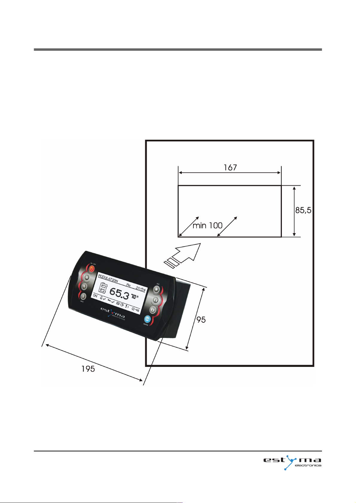
The controller is designed for mounting in a wall or plate mounting. Plate thickness
should not exceed 3mm. The minimum depth of the mounting hole is 100mm. The dimensions
of the hole and controller are indicated in the figure below.
After placing the panel in the hole, always install the mounting frame.
page 10
PL20110629
Page 11
2 Connecting to the system
2.4 Connecting
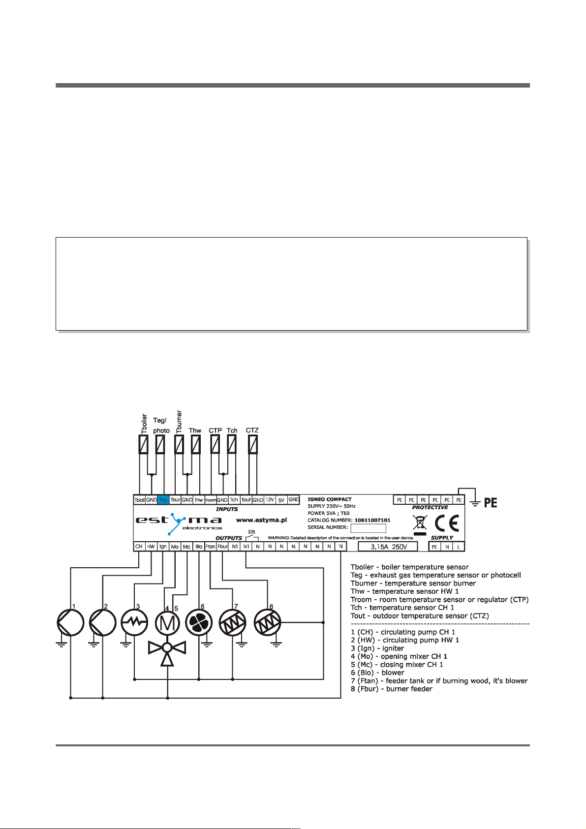
The device supply voltage is ~ 230V/50Hz. Plug the power cord to the controller in
accordance with the posted signs.
Be attached to the controller for operating the boiler sensors and actuators as needed.
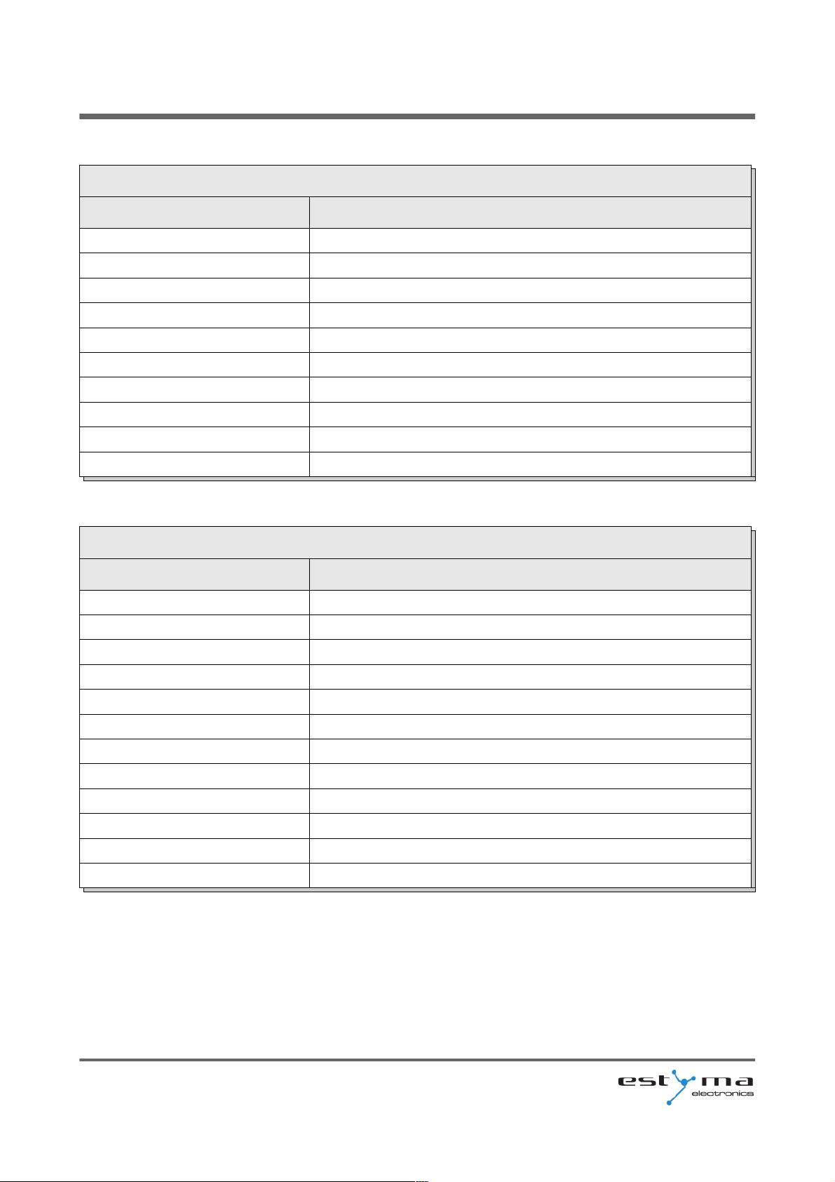
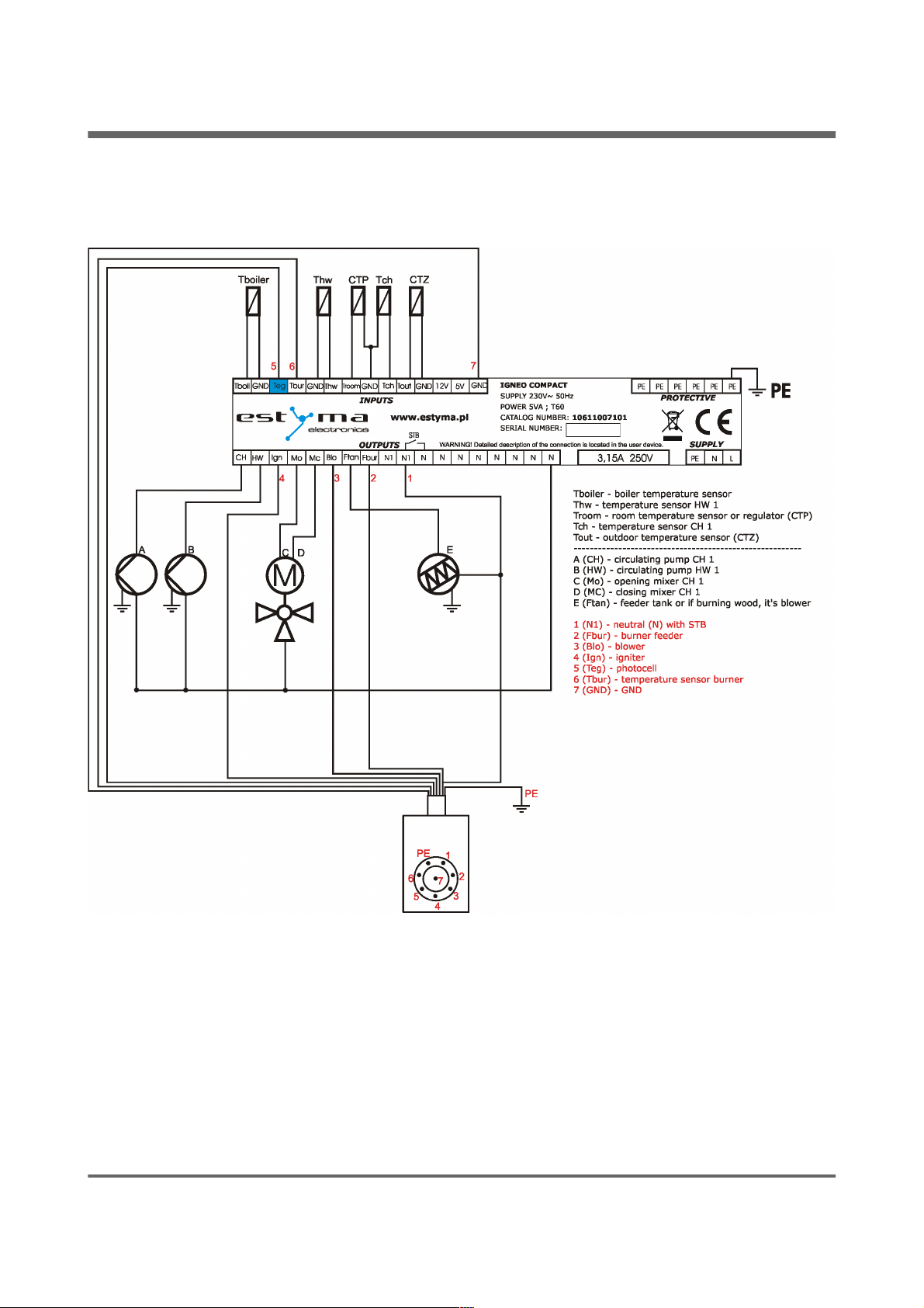
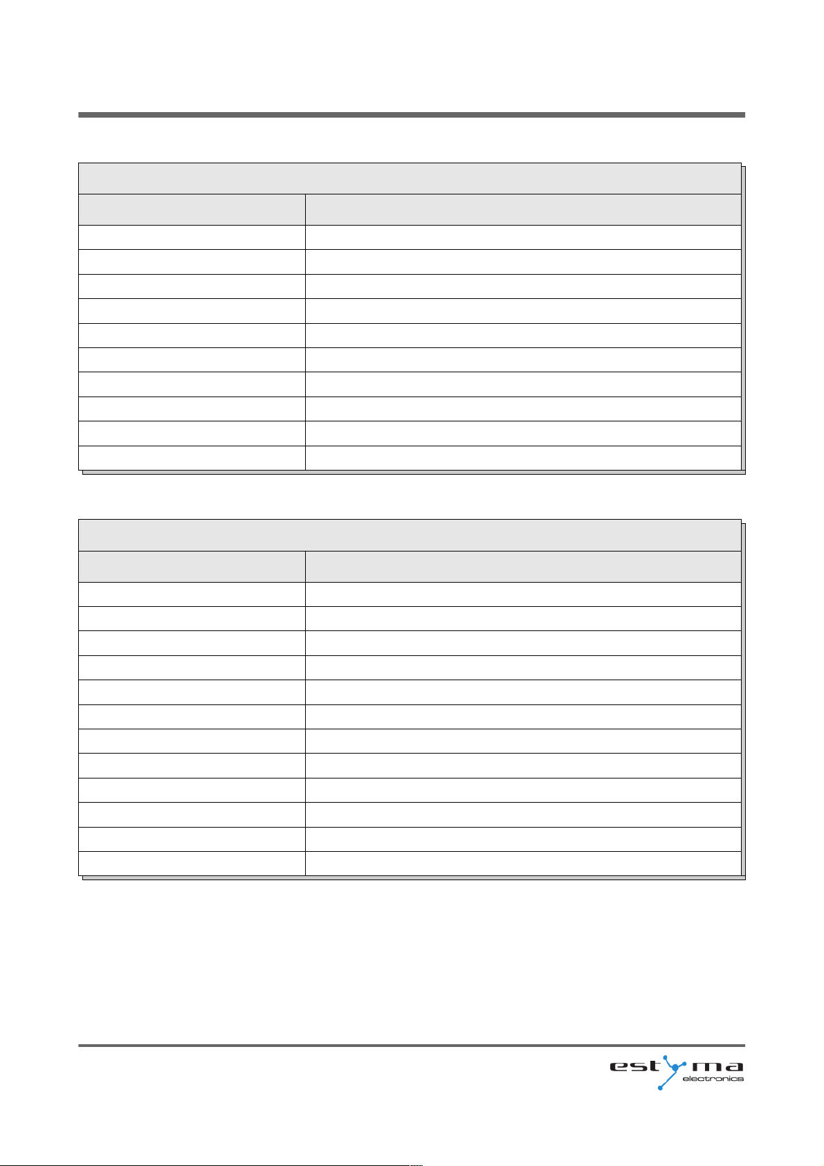
The drawings shows the connection scheme of equipment. In the tables, a description of the
inputs and outputs.
Warning !!! Under no circumstances connect the protective conductor (PE) with a
neutral (N).
Warning !!! Wiring must be done with the device disconnected from the mains.
Connections should be exercised by a person possessing adequate powers in this regard.
2.4.1 Direct connection of devices
estyma electronics
www.estyma.pl
page 11
PL20110629
Page 12
2 Connecting to the system
INPUTS
Description Explanation
Tboiler Boiler temperature sensor
Teg / photo Exhaust gas temperature sensor or photocell
Tburner The temperature sensor burner
Thw The temperature sensor hot water
Troom Room temperature sensor / regulator (CTP)
Tch The temperature sensor central heating
Tout Outdoor temperature sensor (CTZ)
12V +12V output to supply optional equipment
5V +5V output to supply optional equipment
GND Mass electric to connect sensors
OUTPUTS
Description Explanation
1 (CH) Central heating circulating pump
2 (HW) Circulating pump for hot water
3 (Ign) Burner igniter
4 (Mo) Opening the central heating mixer
5 (Mc) Closing the central heating mixer
6 (Blo) Burner blower
7 (Ftan) Feeder tank, or if burning wood, it's blower
8 (Fbur) Burner feeder
STB Protection STB
N Neutral standing
N1 Neutral separable such as by STB
PE Protective
page 12
PL20110629
Page 13
2 Connecting to the system
2.4.2 Connecting using burner wire
estyma electronics
www.estyma.pl
page 13
PL20110629
Page 14
2 Connecting to the system
INPUTS
Description Explanation
Tboiler Boiler temperature sensor
5 (Teg) Photocell
6 (Tbur) The temperature sensor burner
Thw The temperature sensor hot water
Troom Room temperature sensor / regulator (CTP)
Tch The temperature sensor central heating
Tout Outdoor temperature sensor (CTZ)
12V +12V output to supply optional equipment
5V +5V output to supply optional equipment
7 (GND) Mass electric to connect sensors
OUTPUTS
Description Explanation
A (CH) Central heating circulating pump
B (HW) Circulating pump for hot water
4 (Ign) Burner igniter
C (Mo) Opening the central heating mixer
D (Mc) Closing the central heating mixer
3 (Blo) Burner blower
E (Ftan) Feeder tank, or if burning wood, it's blower
2 (Fbur) Burner feeder
1 (N1) Neutral separable such as by STB
STB Protection STB
N Neutral standing
PE Protective
page 14
PL20110629
Page 15
3 Overview of the basic functions
3 Overview of the basic functions
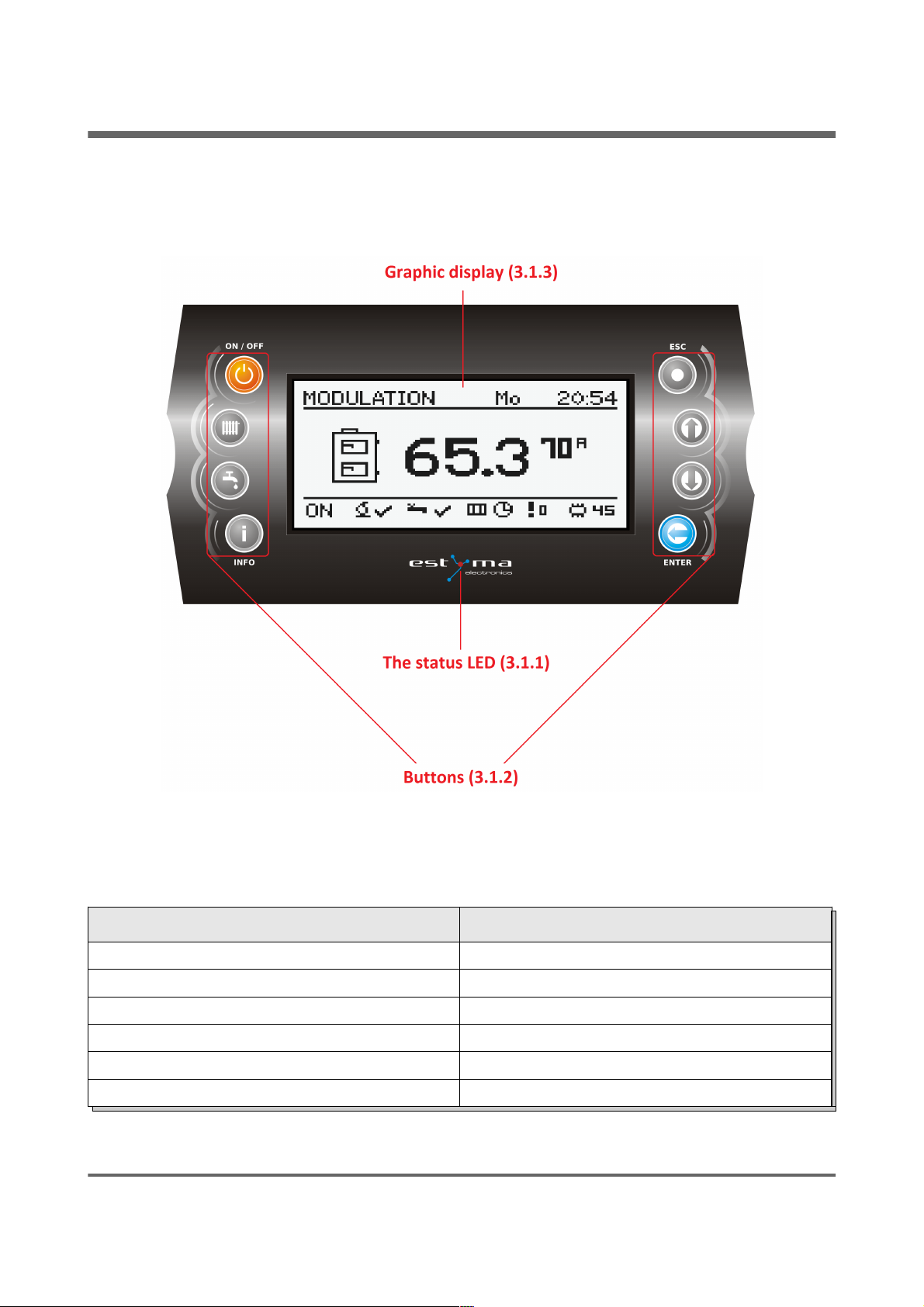
3.1 Control panel
3.1.1 The status LED
Status Importance
Green light continuously Controller OFF
Green blinks Controller enabled, burner OFF
Orange light continuously Controller enabled, burner enabled
Orange blinks Burner works
Red light continuously There is an alarm to be confirmed
Red blinks Alarm active
estyma electronics
www.estyma.pl
page 15
PL20110629
Page 16
3 Overview of the basic functions
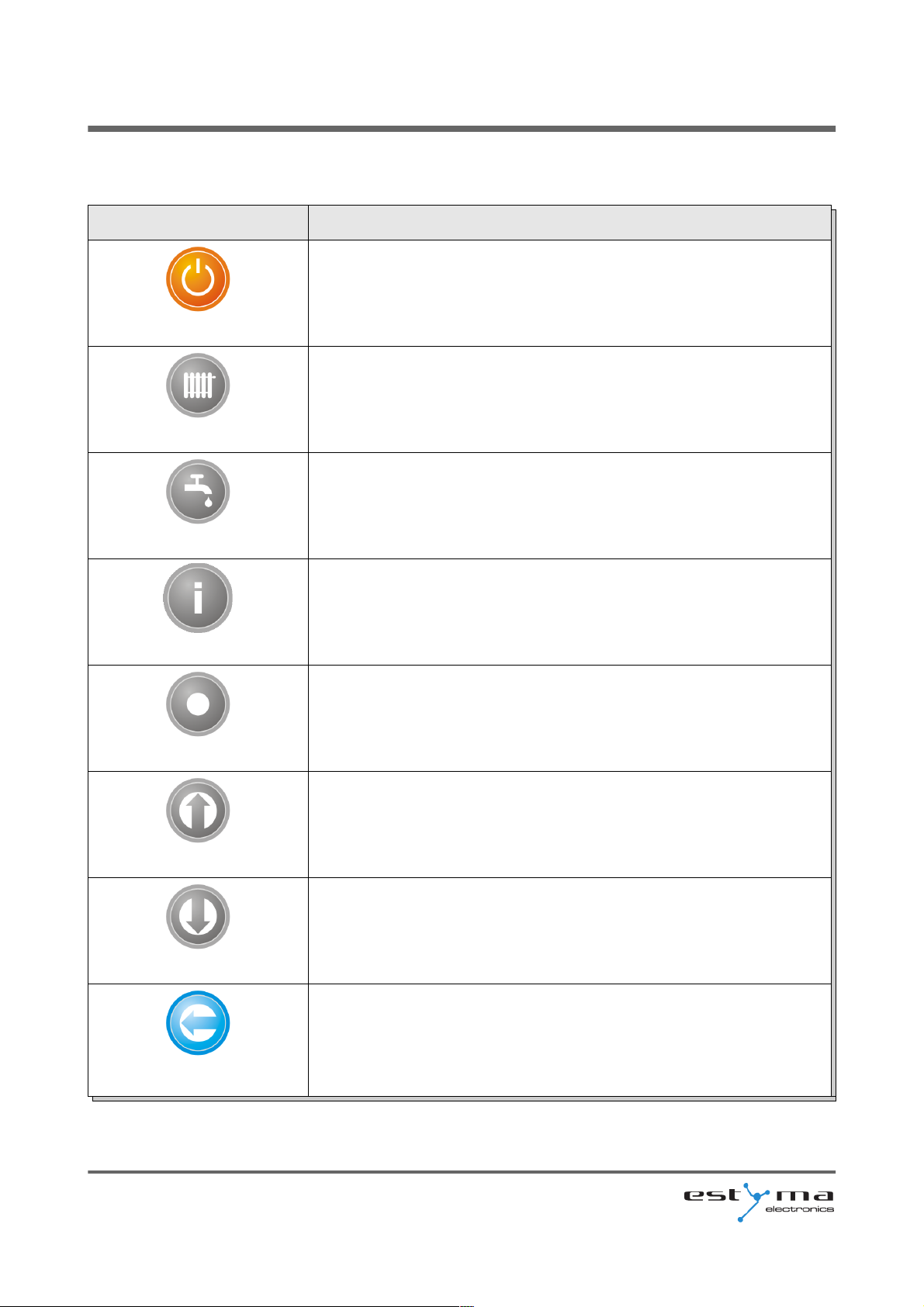
3.1.2 Buttons
Button Function
ON / OFF
Long press on the main screen (>3 seconds) changes the state
of the ON/OFF (on/off).
CH
Quick access to the full configuration settings for the central
heating.
HW
Quick access to the full configuration settings for hot water.
INFO
Shows the navigation information and descriptions of the
regulated parameters.
ESC
Back one level up in the menu, the resignation of the parameter
change.
Up arrow
Navigating through the menus, increasing the value of the
parameter being edited.
On main screen, enter the menu simple.
Down arrow
Navigating through the menus, reducing the value of the
parameter being edited.
On main screen, enter the menu simple.
ENTER
Access to the menu.
Acceptance of changes in the value of the parameter being
edited.
Confirmation of the alarm.
page 16
PL20110629
Page 17
3 Overview of the basic functions
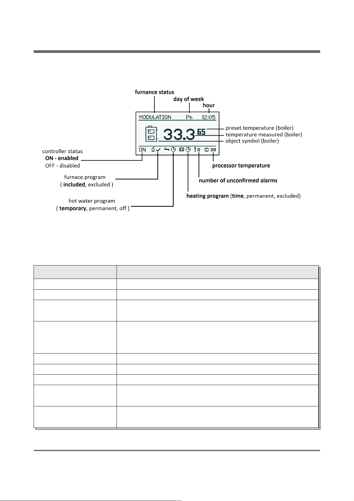
3.1.3 Graphic display
3.2 Statuses of furnace
Status Description
TURNED OFF The burner is not working. Permission to work off.
CLEANING Cleaning the burner by strong stream of air.
FIRING UP Firing up fuel.
Providing the initial dose of fuel to run igniter and blower.
INCANDESCING When the flame in phase of the firing up is discovered, starts
providing additional portions of fuel and increase the power of
blower for arcing furnace.
POWER 1 The burner works with the power first.
POWER 2 The burner works with the power of a second.
MODULATION The burner works with a modulated power.
BURNING OFF Quenching of the furnace. Work of burner and blower tray until
the complete disappearance of the flame.
STOP Burner does not work but it is to agree to his work. The required
boiler temperature is reached.
estyma electronics
www.estyma.pl
page 17
PL20110629
Page 18
4 Handling
4 Handling
4.1 Navigation in the menu
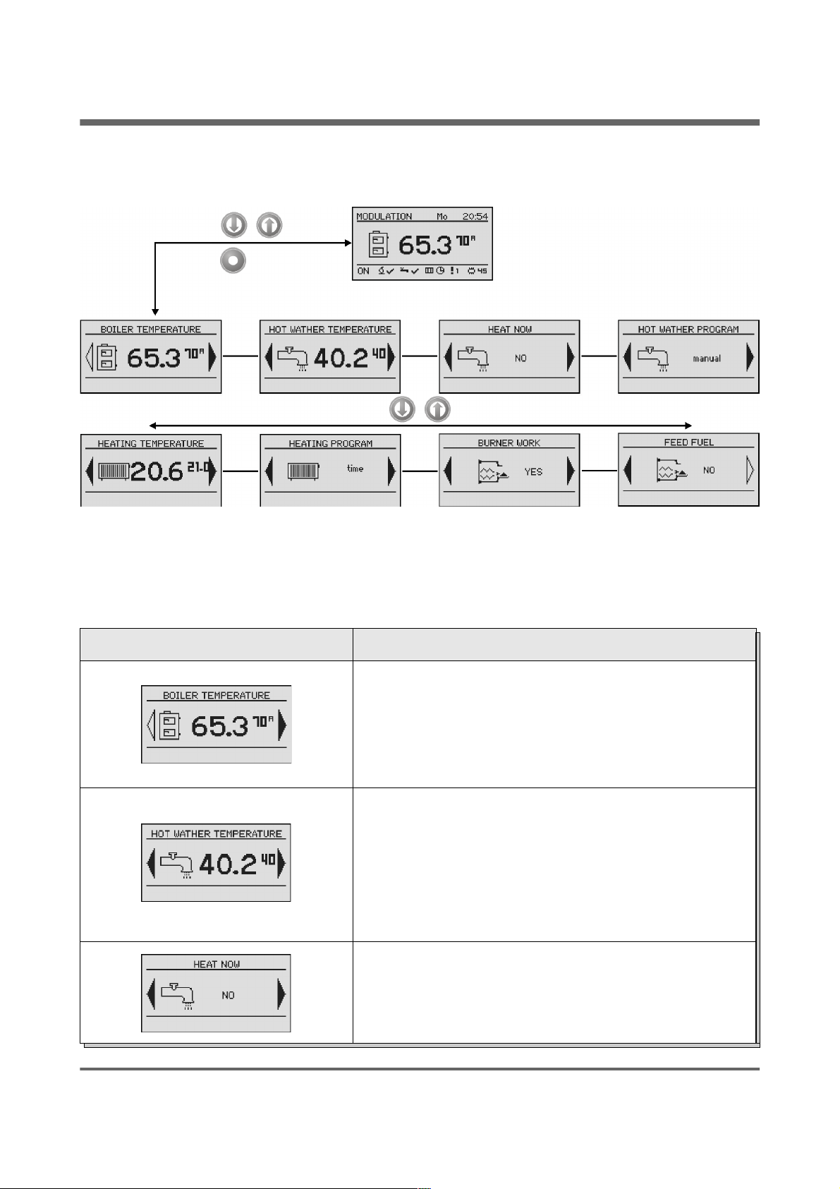
The device has two types of menus: simple and main menus.
Simple menu - allows for quick access to basic controller functions. Enter the menu is simple
by pressing the "up arrow"or "down arrow" on the main screen. Description of a simple menu
in chapter 5.
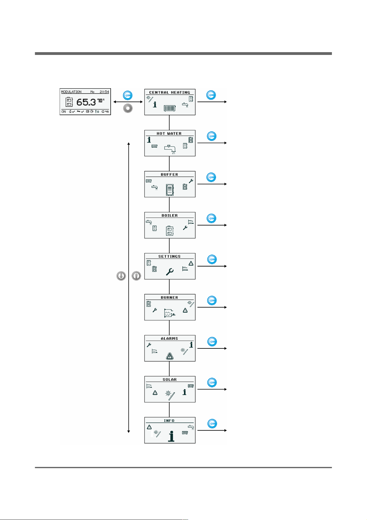
Main menu - allows you to access all the functionality of the controller (monitoring,
adjustments and service settings.) Access to the main menu is done by pressing the button
"Confirm, enter" on the main screen. Description of the main menu in Chapter 6
Back to the main screen is possible from any screen by pressing the button "Back, esc" several
times.
WARNING !!! Access the service is intended only for qualified technical personnel. The
changes may cause malfunction of the system.
4.2 Starting regulator - ON
To run the controller (ON mode) for 3 seconds to press the „ON / OFF” on the screen
when it is in the OFF mode.
4.3 Switching off the regulator - OFF
To turn off the controller (OFF mode) for 3 seconds to press the „ON / OFF” on the
screen when he is in the ON mode.
WARNING !!! When you turn off the controller, depending on the previous state, the
burner can still work (quenching), the state should not be interrupted. If the device is to be
excluded from the power supply, wait quenching process, until the status of the burner is
"off".
page 18
PL20110629
Page 19
4 Handling
4.4 Time scheduling
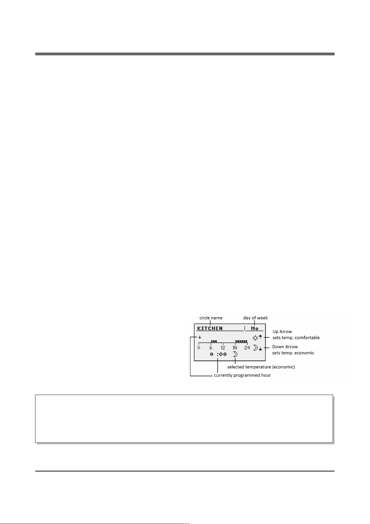
Controller is equipped with a clock and calendar. This makes it possible to program the
operation of individual circuit elements for heating depending on the time and day of week.
Date and time are not reset during a power failure, because the controller is equipped with a
battery that should be replaced every two years.
Programming takes place in the menu of the circuit (eg, hot water, heating, buffer) and
for each item carried in the same way.
Selecting the day of week. Upon entry in the "Programme Time" day of the week
flashes. Arrow buttons to select the day you want to set or just check the settings of the
program.
Programming. After selecting the day of week and approved "ENTER", indicator being
programmed hours flashes. At the same time also displays the time, and the next to it icon
that represents the currently selected setting time (the symbol of the sun means comfort
temperature, the moon is a symbol of the economic temperature.) To move to the next hour,
press the down arrow (economy temperature) or the up arrow (comfort temperature). If the
day is already programmed in accordance with our wish, press "ENTER". After approved the
changes (or cancellation) will blink day of the week.
The figure shows an example of the preset day of the week.
Temp. economy from 00:00 to 6:00
Temp. comfortable from 6:00 to 9:00
Temp. economy from 9:00 to 18:00
Temp. comfortable from 18:00 to 24:00
WARNING !!! Values of temperatures comfortable and economical are set in the
“SETTINGS” menu and may be different for each of the circuits. To make the time program
work, you must also enable a timed mode in the “SETTINGS” menu.
estyma electronics
www.estyma.pl
page 19
PL20110629
Page 20
4 Handling
4.5 Service password
Access to the service parameters are password protected. After entering the correct
password, access will be lifted. Access to the service parameters will be locked after a period of
10 minutes without pushing buttons.
Service code is a temperature of the boiler in menu BOILER / SETTINGS and
3 letters "EST".
Example: If the temperature of the boiler in menu BOILER / SETTINGS is 60 ° C,
password is “60EST”.
WARNING !!! Access the service is intended only for qualified technical personnel. The
changes may cause malfunction of the system.
page 20
PL20110629
Page 21
5 Simple menu
5 Simple menu
5.1 Simple menu screens
Screen Description
Shows the current temperature of the boiler (large
font) and the desired temperature (small font). After
pressing the "ENTER" set the desired temperature of
the boiler.
Shows the current temperature of hot water (large
font) and the desired temperature (small font). After
pressing the "ENTER" set the desired temperature of
hot water.
Menu relates to the circuit No. 1
Disposable heating hot water to a comfortable
temperature regardless of the program.
Menu relates to the circuit No. 1
estyma electronics
www.estyma.pl
page 21
PL20110629
Page 22
5 Simple menu
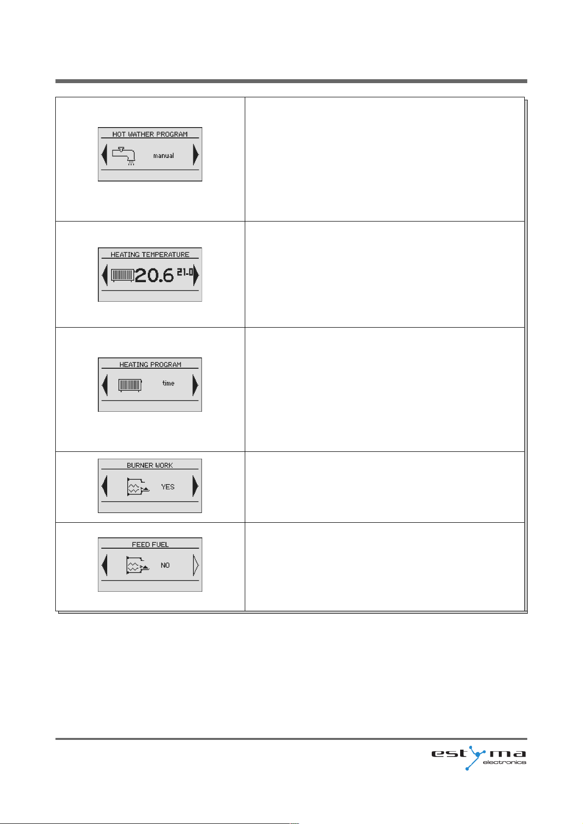
Set the mode a hot water:
a) time - according to the programmed timescales
b) constatant - regardless of the time intervals
comfortable temperature is maintained
c) disabled - off the heat
Menu relates to the circuit No. 1
Shows the current temperature in the room No 1 (large
font) and the value of the desired (small font). After
pressing the "ENTER", go to set the desired
temperature in the room.
Menu relates to the circuit No. 1
Set the mode a heating circuit:
a) time - according to preset ranges
b) constant - regardless of the time intervals
comfortable temperature is maintained
c) disabled - off the heat
Menu relates to the circuit No. 1
Allow for operation of the burner. When not consent to
the burner operation, regulator controls the heating
system, but do not attach the burner.
Manual start of the fuel feed from the tray. Useful
function after the exhaustion of fuel from the cartridge.
After refilling the fuel cartridge, run the "enter fuel"
until the fuel gets into the burner.
page 22
PL20110629
Page 23
6 Main menu
6 Main menu
6.1 Heating
page 24
6.2 Hot water
page 28
6.3 Buffer
page 31
6.4 Boiler
page 33
6.5 Settings
page 35
6.6 Burner
page 38
6.7 Alarms
page 40
6.8 Solar
page 46
6.9 Info
page 47
estyma electronics
www.estyma.pl
page 23
PL20110629
Page 24
6 Main menu
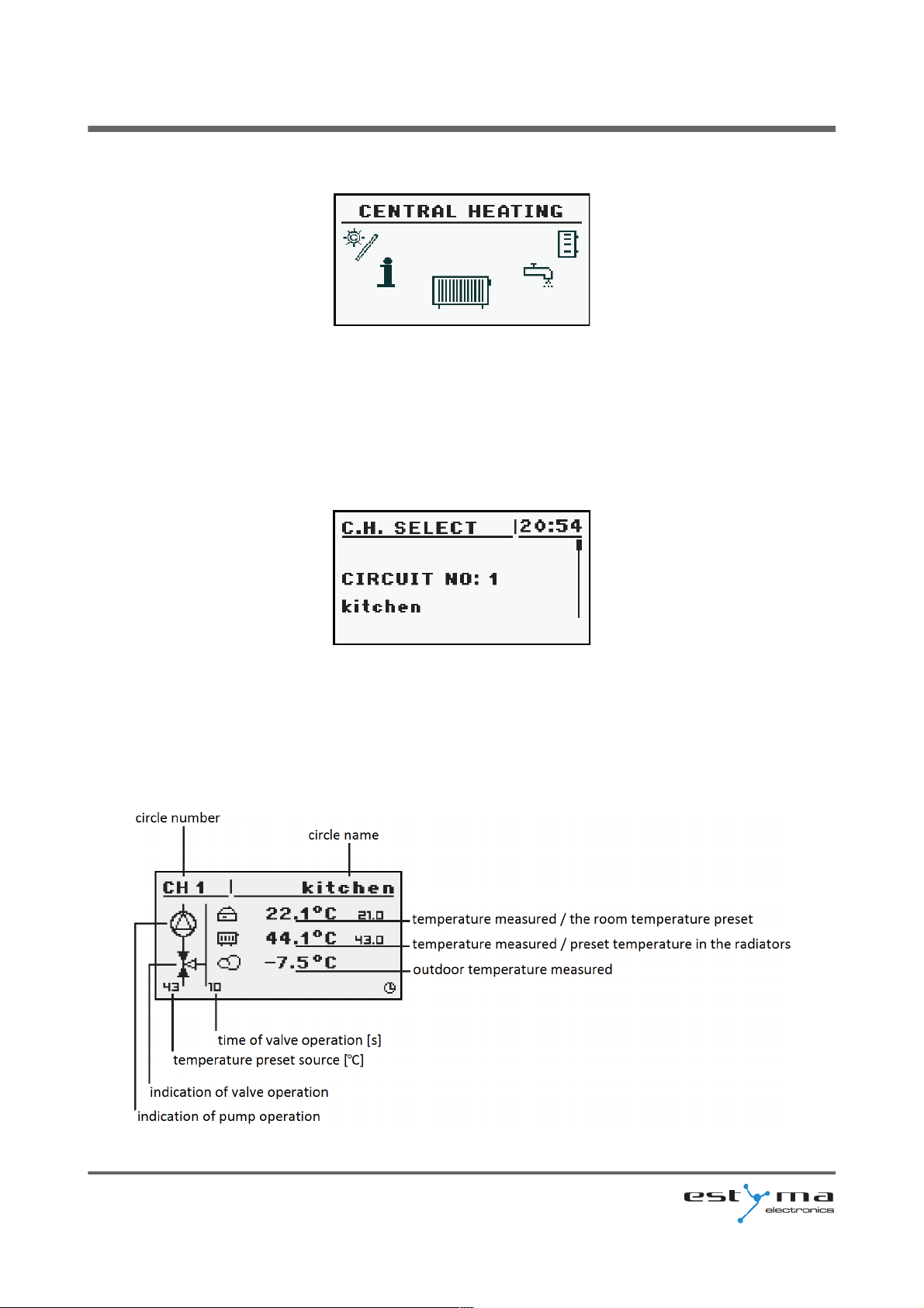
6.1 Heating
6.1.1 Selection of circuit
Allows you to select a number of central heating circuit. The selection of the circuit
make arrows.
6.1.2 State
Allows you to monitor the status of central heating system.
page 24
PL20110629
Page 25

6 Main menu
6.1.3 Settings
Settings
Function Description
Comfortable temp. Desired temperature in the room during the
heating.
Programme Programs:
a) time - according to preset intervals
b) constant - regardless of the time intervals
comfortable temperature is maintained
c) disabled - off the heat
d) economic - in the rooms temperature is
maintained the economic
Economical temp. Desired temperature in the room outside the
period of heating.
6.1.4 Time program
Used to configure the time program steering central heating.
Description of the adjustment time program refer to chapter 4.4.
estyma electronics
www.estyma.pl
page 25
PL20110629
Page 26
6 Main menu
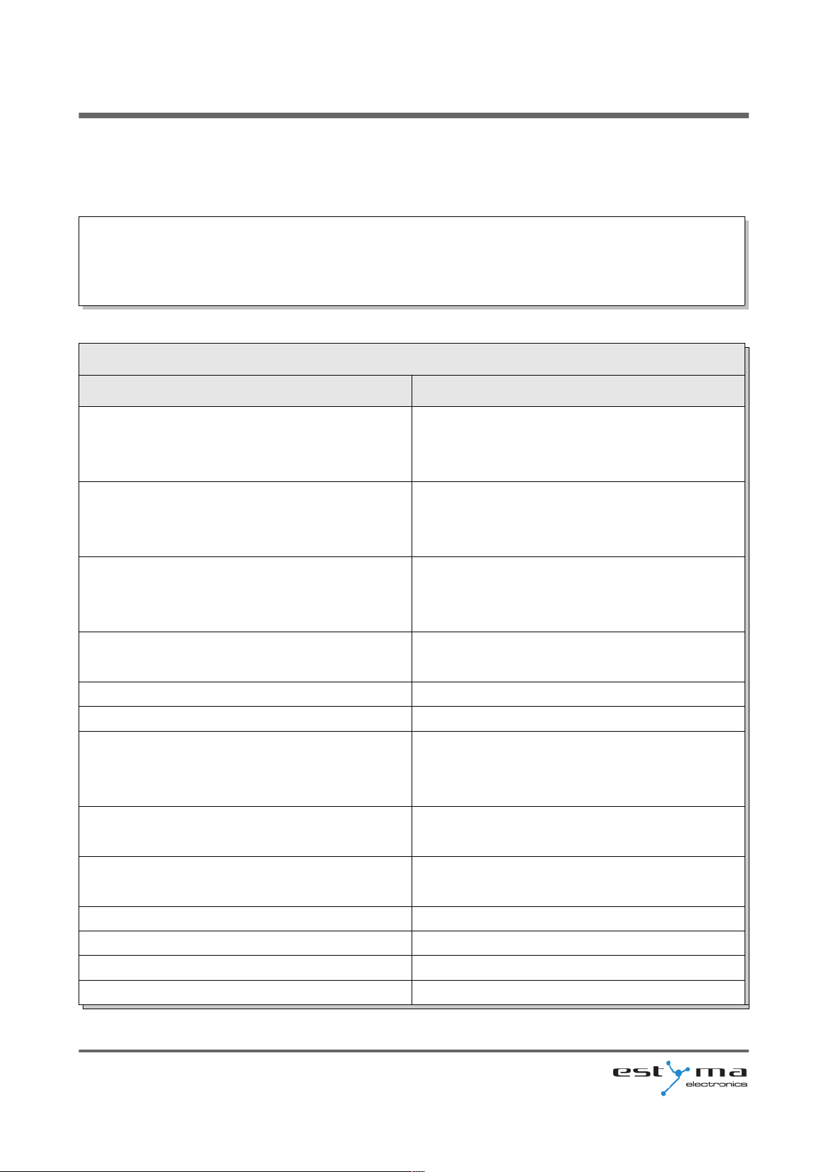
6.1.5 Service
WARNING !!! Access the service is intended only for qualified technical personnel. The
changes may cause malfunction of the system.
Service
Function Description
Comf. MAX pump temp. Maximum outdoor temperature at which the
circulating pump can work in a comfortable
range.
Econ. MAX pump temp. Maximum outdoor temperature at which the
circulating pump can work in a economic
range.
MIN Tch pump Minimum temperature calculated for central
heating at which the circulating pump can be
operated.
Source Specifies the source of energy for central
heating circuit.
Temperature MAX Maximum temperature for central heating.
Mixer time Time of full opening of the mixer.
Hot water priority Priority for hot water of the heating circuit.
During heating hot water the central heating
pump is not working.
Pump test Starts the pump regardless of other
conditions.
Mixer test Starts the mixer motor independently of the
other conditions.
Circ. name Gives name for the central heating circuit.
CH temp. for -20°C The point of the heating curve for -20 ° C.
CH temp. for 0°C The point of the heating curve for 0 ° C.
CH temp. for 10°C The point of the heating curve at 10 ° C.
page 26
PL20110629
Page 27

6 Main menu
Service
CH temp. for corr. factor Central heating temperature correction
required the desired room temperature for 1 º
C. For example, if the correction factor is set
at 6 ° C, room temperature set at 20 ° C and
measured in the room is 20.5 ° C then the
temperature calculated at will be reduced by
3 ° C.
Mode type Specifies the input mode central heating
temperature:
manual - the temperature of central heating
inflicted manually,
weather - the temperature of central heating
calculated from the heating curve.
Manual Tch The desired temperature of central heating
when the mode is set to manual.
Room temp. sensor Specifies whether the system uses a room
sensor.
CH temp. sensor Specifies whether the system uses a sensor
heating.
Permanent pump Yes - the pump runs at a given temperature
in the room, reduced the temperature for
heating (only with the use of a sensor for
central heating and room sensor),
No - after reaching the set temperature in the
room the pump is turned off.
estyma electronics
www.estyma.pl
page 27
PL20110629
Page 28
6 Main menu
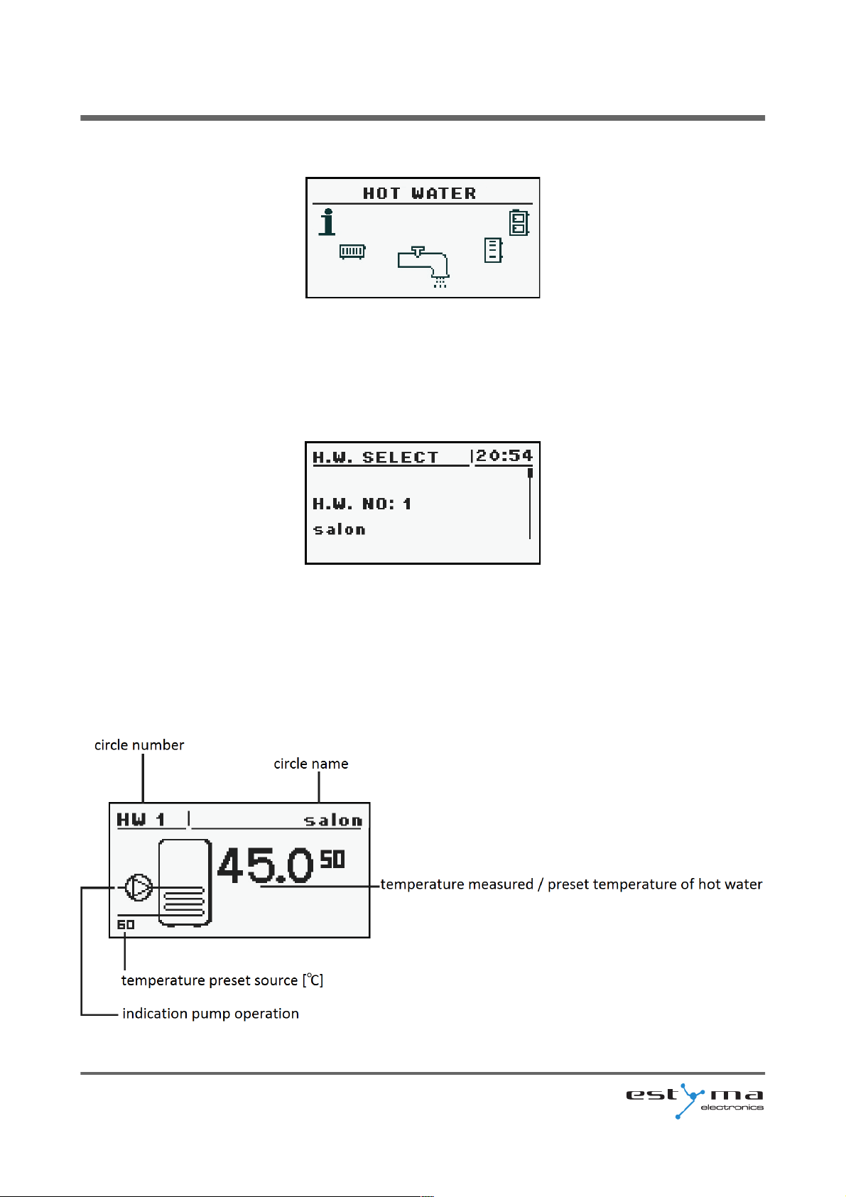
6.2 Hot water
6.2.1 Selection of circuit
Allows you to select the number of hot water circuit.
6.2.2 State
Allows you to monitor the status of hot water.
page 28
PL20110629
Page 29
6 Main menu
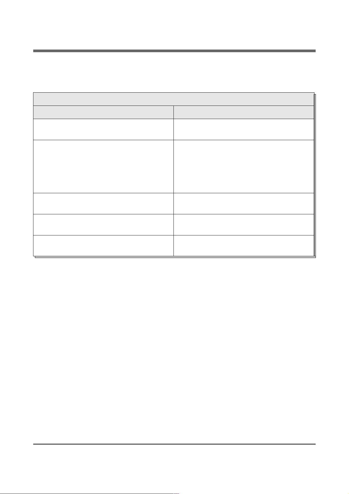
6.2.3 Settings
Settings
Function Description
Comfortable temp. Desired temperature of hot water during
heating.
Programme Set the mode a circuit:
a) time - according to preset ranges
b) constant - regardless of the time intervals
comfortable temperature is maintained
c) disabled - off the heat.
Heat now Heats hot water once to a comfortable
temperature regardless of the program.
Hysteresis The value of which can reduce the
temperature of hot water.
Economical temp. Desired temperature of hot water outside the
period of heating.
6.2.4 Time program
Used to configure the time steering hot water preparation.
Description of the adjustment time refer to chapter 4.4.
estyma electronics
www.estyma.pl
page 29
PL20110629
Page 30
6 Main menu
6.2.5 Service
WARNING !!! Access the service is intended only for qualified technical personnel. The
changes may cause malfunction of the system.
Service
Function Description
Source delta Increasing the temperature of the source of
the desired temperature of hot water during
heating.
Source Specifies the source of energy for hot water.
Temperature MAX Maximum temperature of hot water.
Delta MIN temp. The minimum temperature difference
between the source and the hot water at
which the pump can work.
Pump test Starts the pump regardless of other
conditions.
Circ. name Gives name for the hot water circuit.
page 30
PL20110629
Page 31
6 Main menu
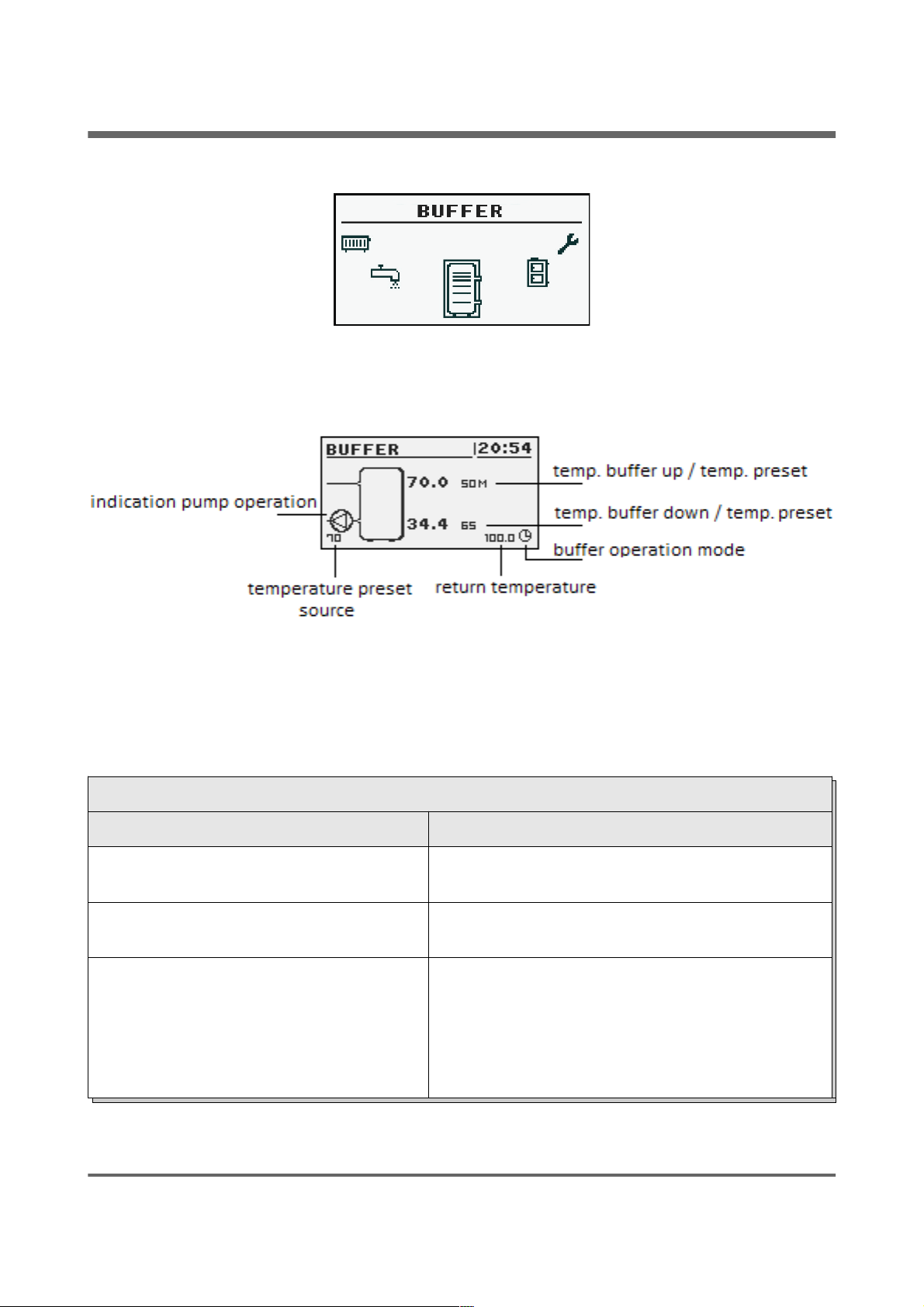
6.3 Buffer
6.3.1 State
6.3.2 Settings
Settings
Function Description
Upper set temperature Below this temperature in the upper part of the
buffer starts charging.
Lower set temperature Above this temperature at the bottom of a buffer
completes the process of charging.
Programme Constant - the buffer is charged regardless of the
time,
time - the buffer charged only at specified
intervals. Intervals are set in the "time program",
disabled - off charging buffer.
estyma electronics
www.estyma.pl
page 31
PL20110629
Page 32
6 Main menu
6.3.3 Time program
Used to configure time program to controlling charging buffer.
Description of program adjustment time refer to chapter 4.4.
6.3.4 Service
WARNING !!! Access the service is intended only for qualified technical personnel. The
changes may cause malfunction of the system.
Service
Function Description
Minimal pump temp. The minimum temperature in the upper part
of the buffer at which the circulating pump
can work for central heating.
Auto upper temp. Specifies whether the upper temperature
buffer (minimum) is requested manually or
automatically. Automatically based on the
needs of other power consumers in the buffer.
page 32
PL20110629
Page 33
6 Main menu
6.4 Boiler
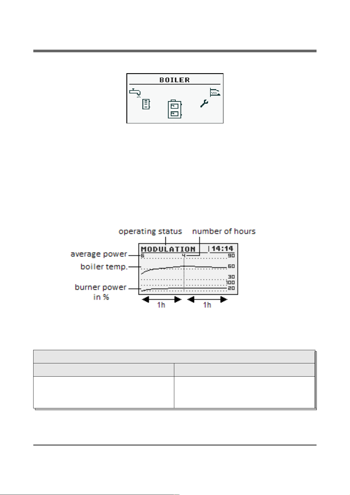
6.4.1 State
Statistics of the boiler in the past 24 hours. The graph shows the temperature of the
boiler and power of burner. "Hours" refers to how many hours ago the boiler behaved these
operating parameters. Across the screen are displayed statistics of 2 hours. Screens switching
buttons "up" and "down".
6.4.2 Settings
Settings
Function Description
Boiler temp. set Heating water temperature in the boiler which
will be maintain the controller. Menu is active
only in continuous work mode.
estyma electronics
www.estyma.pl
page 33
PL20110629
Page 34
6 Main menu
6.4.3 Service
WARNING !!! Access the service is intended only for qualified technical personnel. The
changes may cause malfunction of the system.
Service
Function Description
MIN pump temp. The temperature above which the the controller
can attach pumps.
Mode Operating mode of boiler:
a) auto - temperature calculated automatically
b) continuous - the temperature is kept constant
Hysteresis The temperature of the boiler must be reduced
by this value to launch the burner.
MIN return temp. Minimal return to boiler temperature maintain by
mixer.
Return mixer time Specifies the time of full opening of the return
mixer.
Boiler pump test Starts boiler pump regardless of other
conditions.
Return mixer test Starts actuator of the return mixer regardless of
other conditions.
page 34
PL20110629
Page 35
6 Main menu
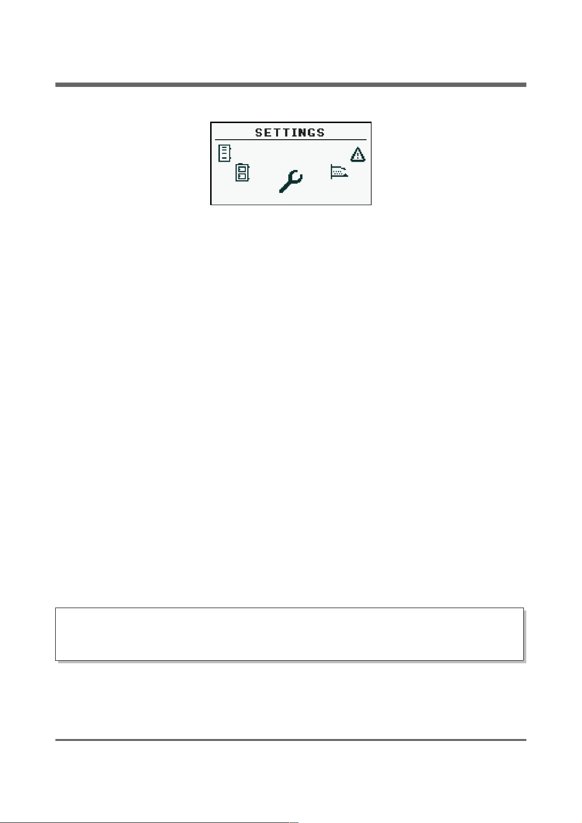
6.5 Settings
6.5.1 Date and time
Using this menu is made to set the date and time of the driver.
6.5.2 Language
Use this menu to select language of the menu.
6.5.3 General settings
6.5.3.1 Alarm buzzer
We define here, if the driver shall notify of alarms by acoustic signal.
6.5.4 Service
WARNING !!! Access the service is intended only for qualified technical personnel. The
changes may cause malfunction of the system.
estyma electronics
www.estyma.pl
page 35
PL20110629
Page 36
6 Main menu
6.5.4.1 Module configuration
Menu is used to configure the CAN network. In the menu, select the modules that are
connected to the system.
WARNING !!! A detailed description of the modules and their destination are described
in the manual of expansion modules.
SUMMARY OF THE EXPANSION MODULES
Module Description
Module no. 0 3 heating circuits of the numbers 2,3,4.
Outdoor temperature sensor.
Module no. 1 3 heating circuits of the numbers 5,6,7.
Module no. 2 3 heating circuits of the numbers 8,9,10.
Module no. 3 3 heating circuits of the numbers 11,12,13.
Module no. 4 3 heating circuits of the numbers 14,15,16.
Module no. 5 Buffer.
Solar collectors.
Hot water no. 2.
Return temperature sensor.
Module no. 6 Not used.
Module no. 7 Not used.
Module Lambda Module of the Lambda sensor.
page 36
PL20110629
Page 37
6 Main menu
6.5.4.2 System configuration
Menu is used to configure the heating system (hydraulic). The possibility of settings is
dependent of number of expansion modules connected in the system.
WARNING !!! You must first configure the modules.
SYSTEM CONFIGURATION
Function Description
Number of CH circuits Specifies the number of heating circuits in the
system.
Number of HW circuits Specifies the number of hot water circuits in
the system.
Number of buffers Specifies the number of buffors in the system.
Outside temp. sensor Specifies if in the system is installed outside
temperature sensor (module 0).
Return temp. sensor Specifies if in the system is installed return
temperature sensor (module 5).
Solars Specifies if the system is equipped with solar
collectors.
6.5.4.3 Restore to factory settings
This function allows the controller to restore the factory settings.
WARNING !!! Will be restored all factory settings, which can cause your system to
malfunction. After restoring the factory settings may be need to reconfigure the controller
settings.
estyma electronics
www.estyma.pl
page 37
PL20110629
Page 38
6 Main menu
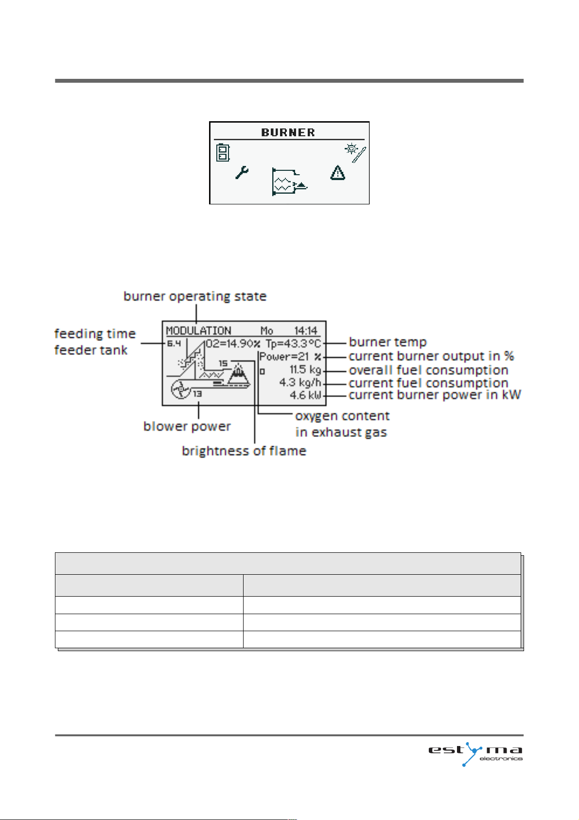
6.6 Burner
6.6.1 State
6.6.2 Settings
Settings
Function Description
Feed fuel now Starts fuel feeding screw regardless of other features.
Burner on Consent to work of the burner.
Fuel type Specifies the type of fuel.
page 38
PL20110629
Page 39
6 Main menu
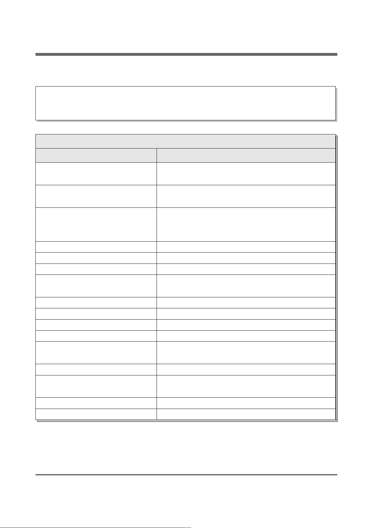
6.6.3 Service
WARNING !!! Access the service is intended only for qualified technical personnel. The
changes may cause malfunction of the system.
Service
Function Description
Air MIN (20%)
Minimum amount of air during modulation where
power of burner is 20% or power number is 1.
Air MAX (100%)
Maximum amount of air during modulation where
power of burner is 100% or power number is 2.
Feeding MAX (100%)
Maximum time during fuel feeding when power of
modulation is 100% or power number is 2 on every 20
seconds.
Power MIN (FL2) Minimal burner power during modulation.
Power MAX (FL2) Maximal burner power during modulation.
Modulation type Burner mode, power modulation or two power levels.
Photo threshold
Brightness in the the burner over which is recognized
as a fire.
Igniter test
*
Turn on igniter for testing.
Heater feeder test
*
Turn on burner feeder for testing.
Storage feeder test
*
Turn on storage feeder for testing.
Blower test
*
Turn on blower for testing.
Test fuel mass
Fuel mass obtained during continuous fuel feeder work
through 1 hour (in kg).
Fuel calorific value Fuel calorific value (in kWh/kg).
Lambda control
Determine whether regulator consider or not oxygen
concentration.
Oxygen MIN (20%) Oxygen target for minimal power.
Oxygen MAX (100%) Oxygen target for maximal power.
* testing equipment in the menu “BURNER” is only possible when the controller is in the OFF
mode.
estyma electronics
www.estyma.pl
page 39
PL20110629
Page 40
6 Main menu
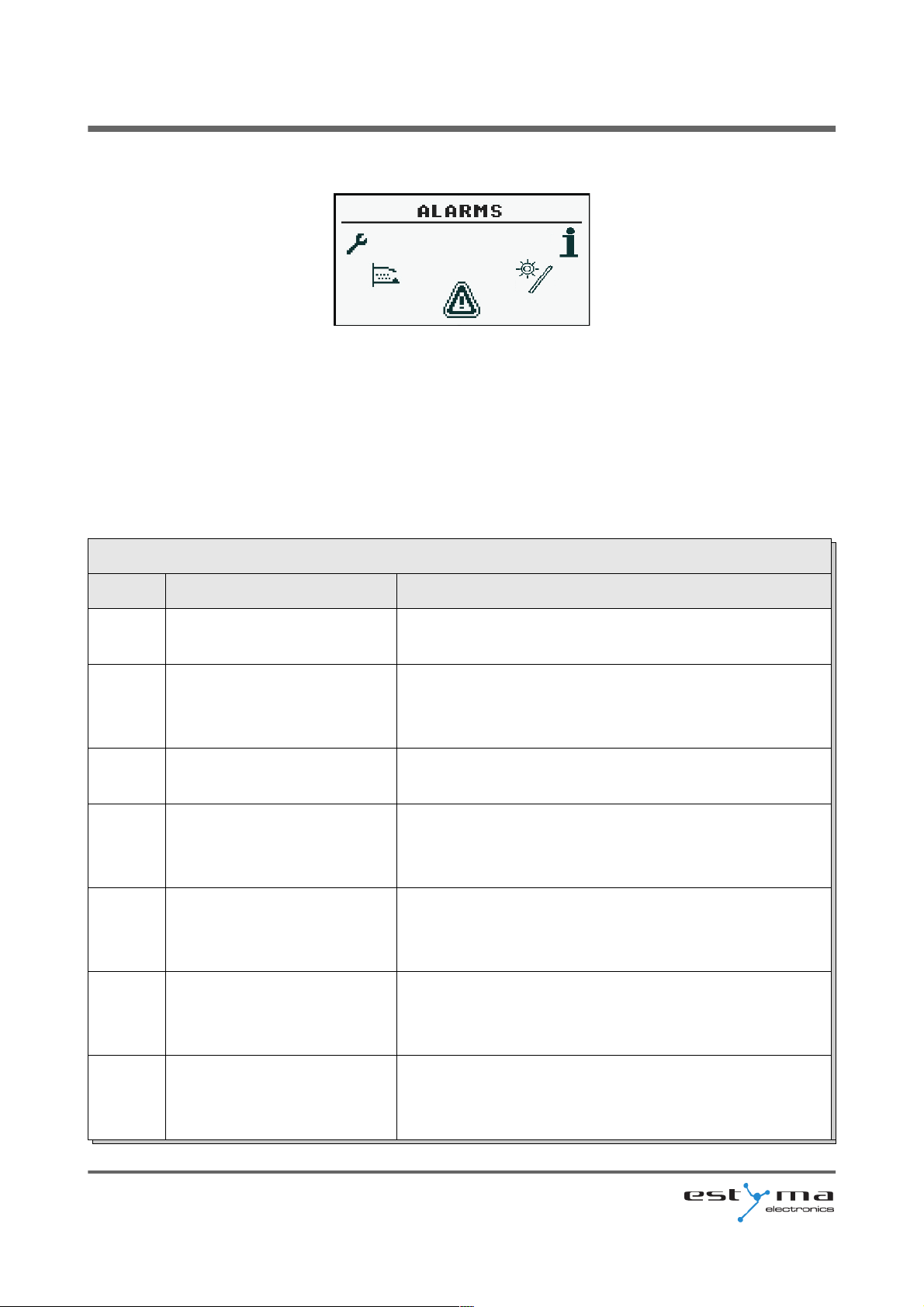
6.7 Alarms
This menu contains a history of up to 20 alarms that occurred during the controller work. The
importance of alarm codes was presented in table below.
6.7.1 Alarm codes
ALARM CODES AND THEIR SIGNIFICANCE
CODE Short description Explanation
1 Processor overheating
Procesor overheating. The reason may be improper
installation location of the controller.
2 No fire / fuel
The controller detected a lack of flame in the burner.
The reason could be the end of the fuel or the flame
goes out.
3 Burner overheating
The temperature of the burner has reached its
maximum value!
4 Boiler sensor shorted
The controller detected shorted boiler temperature
sensor. The reason may be damaged sensor or
connection cable.
5 Boiler sensor open
The controller detected open boiler temperature
sensor. The reason may be damaged sensor or
connection cable.
6 Burner sensor shorted
The controller detected shorted burner temperature
sensor. The reason may be damaged sensor or
connection cable.
7 Burner sensor open
The controller detected open burner temperature
sensor. The reason may be damaged sensor or
connection cable.
page 40
PL20110629
Page 41

6 Main menu
8 Boiler overheating Boiler temperature has exceeded the maximum value!
9 Processor reset
Probable damage the controller!
Possible to loss of power supply.
10 STB
11
Communication with module
0
12
Communication with module
1
13
Communication with module
2
14
Communication with module
3
15
Communication with module
4
16
Communication with module
5
17
Communication with module
6
18
Communication with module
7
19 HW sensor shorted
20 HW sensor open
21 Room temp. sensor shorted
22 Room temp. sensor open
23 Quenching error
24 Lambda communication
25 Solars overheating
26 Solars freezing
The codes of the modules
33 Shorted IN1 Module 0
34 Shorted IN2 Module 0
35 Shorted IN3 Module 0
36 Shorted IN4 Module 0
37 Shorted IN5 Module 0
38 Shorted IN6 Module 0
estyma electronics
www.estyma.pl
page 41
PL20110629
Page 42

6 Main menu
39 --
40 --
41 --
42 --
43 Shorted IN11 Module 0
44 --
45 Open IN1 Module 0
46 Open IN2 Module 0
47 Open IN3 Module 0
48 Open IN4 Module 0
49 Open IN5 Module 0
50 Open IN6 Module 0
51 --
52 --
53 --
54 --
55 Open IN11 Module 0
56 --
57 --
58 Overheating Module 0
65 Shorted IN1 Module 1
66 Shorted IN2 Module 1
67 Shorted IN3 Module 1
68 Shorted IN4 Module 1
69 Shorted IN5 Module 1
70 Shorted IN6 Module 1
71 --
72 --
73 --
74 --
75 --
76 --
77 Open IN1 Module 1
78 Open IN2 Module 1
79 Open IN3 Module 1
page 42
PL20110629
Page 43

6 Main menu
80 Open IN4 Module 1
81 Open IN5 Module 1
82 Open IN6 Module 1
83 --
84 --
85 --
86 --
87 --
88 --
89 --
90 Overheating Module 1
97 Shorted IN1 Module 2
98 Shorted IN2 Module 2
99 Shorted IN3 Module 2
100 Shorted IN4 Module 2
101 Shorted IN5 Module 2
102 Shorted IN6 Module 2
103 --
104 --
105 --
106 --
107 --
108 --
109 Open IN1 Module 2
110 Open IN2 Module 2
111 Open IN3 Module 2
112 Open IN4 Module 2
113 Open IN5 Module 2
114 Open IN6 Module 2
115 --
116 --
117 --
118 --
119 --
120 --
estyma electronics
www.estyma.pl
page 43
PL20110629
Page 44

6 Main menu
121 --
122 Overheating Module 2
129 Shorted IN1 Module 3
130 Shorted IN2 Module 3
131 Shorted IN3 Module 3
132 Shorted IN4 Module 3
133 Shorted IN5 Module 3
134 Shorted IN6 Module 3
135 --
136 --
137 --
138 --
139 --
140 --
141 Open IN1 Module 3
142 Open IN2 Module 3
143 Open IN3 Module 3
144 Open IN4 Module 3
145 Open IN5 Module 3
146 Open IN6 Module 3
147 --
148 --
149 --
150 --
151 --
152 --
153 --
154 Overheating Module 3
161 Shorted IN1 Module 4
162 Shorted IN2 Module 4
163 Shorted IN3 Module 4
164 Shorted IN4 Module 4
165 Shorted IN5 Module 4
166 Shorted IN6 Module 4
page 44
PL20110629
Page 45

6 Main menu
167 --
168 --
169 --
170 --
171 --
172 --
173 Open IN1 Module 4
174 Open IN2 Module 4
175 Open IN3 Module 4
176 Open IN4 Module 4
177 Open IN5 Module 4
178 Open IN6 Module 4
179 --
180 --
181 --
182 --
183 --
184 --
185 --
186 Overheating Module 4
193 Shorted IN1 Module 5
194 Shorted IN2 Module 5
195 Shorted IN3 Module 5
196 Shorted IN4 Module 5
197 --
198 Shorted IN6 Module 5
199 Shorted IN7 Module 5
200 Shorted IN8 Module 5
201 Shorted IN9 Module 5
202 --
203 --
204 --
205 --
206 Overheating Module 5
estyma electronics
www.estyma.pl
page 45
PL20110629
Page 46
6 Main menu
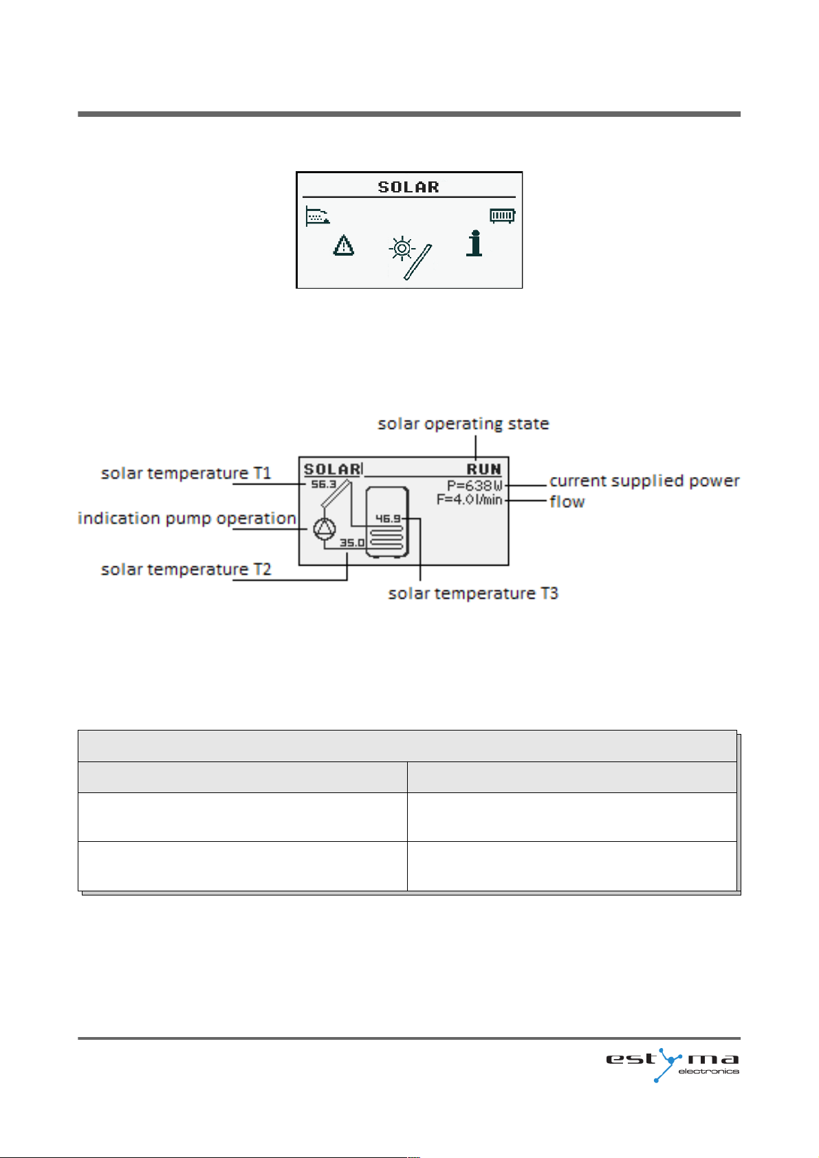
6.8 Solar
6.8.1 State
6.8.2 Settings
Settings
Function Description
Turn on delta Temp. difference between solar and
accumulator needed for solar pump turn on.
Turn off delta Temp. difference between solar and
accumulator needed for solar pump turn off.
page 46
PL20110629
Page 47
6 Main menu
6.8.3 Service
Service
Function Description
Schematic Solar system schematic.
Flow [l/min] Heating fluid flow in l/min.
Fluid specific heat Specific heat of heat-transfer fluid [kJ/
(kg*K)].
MAX HW temp. Over this hot water temp. solar pump is turn
off.
Solar alarm temp. MAX Maximal temp. of solar collector. Alarm and
damage preservation procedure are taken
over this temp.
Solar alarm temp MIN Minimal temp. of solar collector. Alarm and
antifreeze procedure are taken under this
temp.
Solar pump test Allow for solar pump testing.
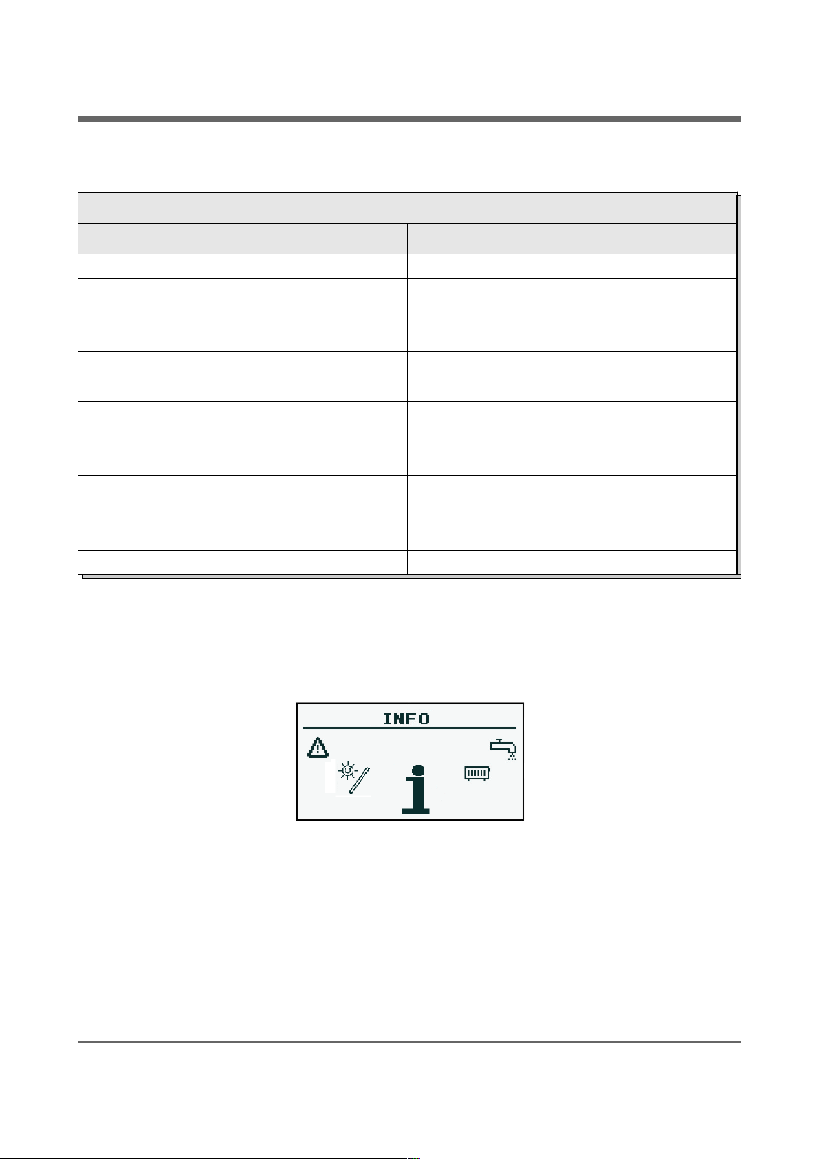
6.9 Info
There you will find useful information about the controller, including the version of software.
estyma electronics
www.estyma.pl
page 47
PL20110629
Page 48
7 Expansion of the system - CAN bus
7 Expansion of the system - CAN bus
The controller is equipped with a high bandwidth CAN bus used to communicate with
the modules. Thanks to the well-known for their reliability, widely used in automotive bus
system is expandable to the highest level.
Use of CAN bus carries several advantages. Gain above all the possibility of using
broadband Lambda oxygen sensor and the using additional of expansion modules
rozszerzeniowych I / O we can install throughout the system:
– to 16 are heating circuits,
– 2 circuits of hot water,
– heat storage tank (buffer),
– solar system (solars).
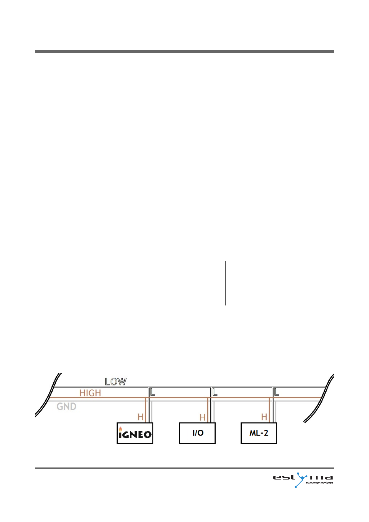
Socket CAN bus is on the left side of the device. Connecting cable must be connected
according to the following designation.
Cable connection:
L – line LOW (white)
H – line HIGH (brown)
GND – ground (grey)
For connections on the CAN bus should be only used cable LiYCY 2x0,25.
Only this type of cable gives the proper work of devices. Connections perform in a serial
manner, this represents a figure below.
page 48
PL20110629
Page 49

7 Expansion of the system - CAN bus
Plugging in expansion modules you need to remember to correctly set the terminator,
which should be attached only at the last module throughout the system, even if the module is
the only one.
After performing all the connections you must configure the module settings. Make this
by selecting the modules that are connected to the network. More about the configuration each
of expansion modules can be found in chapter 6.5.4.1 and instruction of the enlargement
module I/O.
After finishing configuration of expansion modules to do remains only a change the
system settings. Menu is used to configuration the heating system and the possibility of
settings is dependent of number of arranged expansion modules. The table describing the
functions refer to chapter 6.5.4.2.
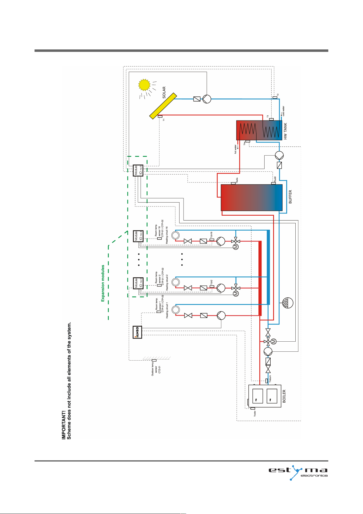
On the next page is a sample diagram of the system. Please note that this is only
overhead view, not containing all the elements of the system.
estyma electronics
www.estyma.pl
page 49
PL20110629
Page 50
7 Expansion of the system - CAN bus
page 50
PL20110629
Page 51
7 Expansion of the system - CAN bus
7.1 Sonda Lambda
Lambda sensor we can connect to the system in two ways:
– directly to the controller, if the entire system with CAN bus module will only use
Lambda oxygen sensor,
– through enlargement module I/O with the number 5, if in the system there are
other modules enlargement.
After connecting the module configure the controller yet. For this purpose, proceed as
explained below.
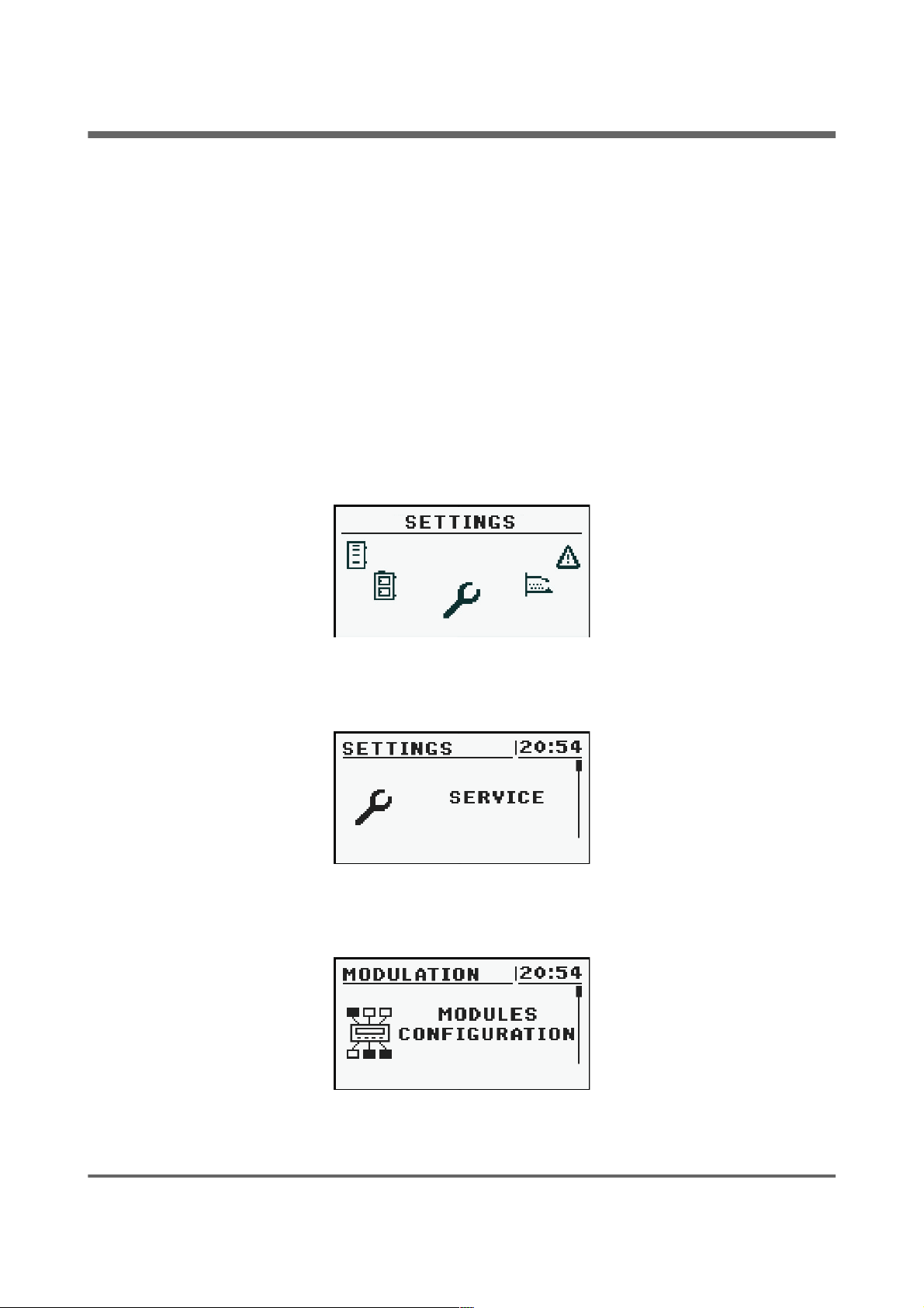
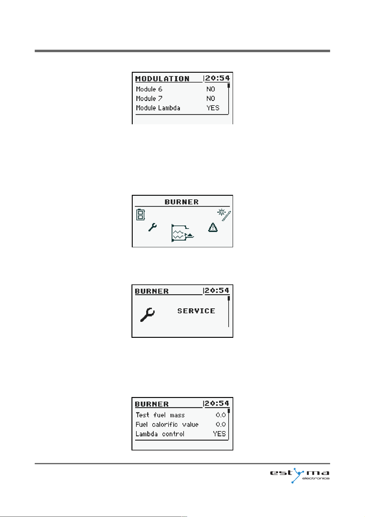
From the main menu select SETTINGS
Then in the mode SERVICE enter the access code
After inputting the correct code, run the MODULES CONFIGURATION
estyma electronics
www.estyma.pl
page 51
PL20110629
Page 52
7 Expansion of the system - CAN bus
Find Lambda Module and turn it on by changing the option to YES
At this point, turned on the module Lambda. The second step is a change the configuration
settings for the burner.
From the main menu by selecting BURNER we get to the settings
Here you can again enter the mode SERVICE and if required, enter the access code
In the list, you can locate the position Lambda control, which switches on YES.
It is also possible working with switched off Lambda control mode. Then Lambda oxygen
sensor module will be responsible only for displaying the measurements.
page 52
PL20110629
Page 53
7 Expansion of the system - CAN bus
7.2 Solars
Solar collectors are supported only by enlargement module I/O number 5th. After
performing all the connections you must configure the controller to work with collectors
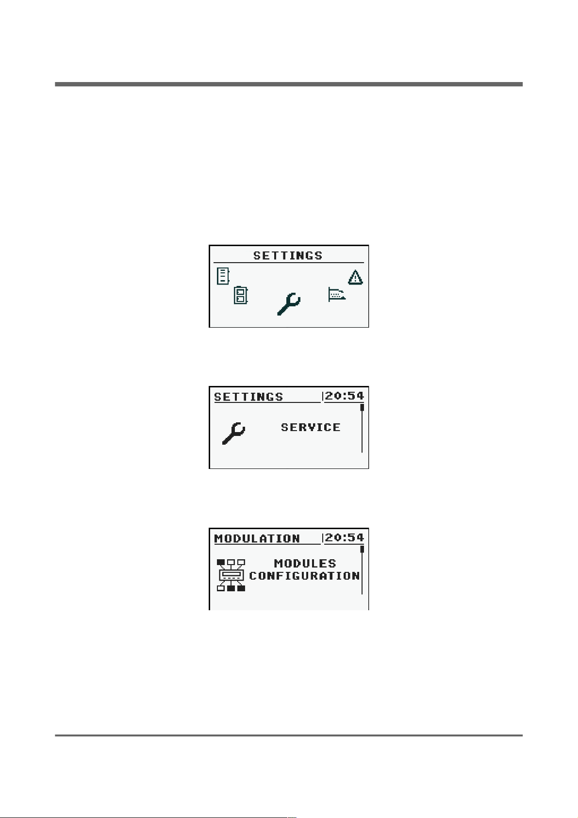
proceed as described below. The first step is to enable module number 5.
From the main menu select SETTINGS
Then in the mode SERVICE enter the access code
After inputting the correct code, run the MODULES CONFIGURATION
estyma electronics
www.estyma.pl
page 53
PL20110629
Page 54
7 Expansion of the system - CAN bus
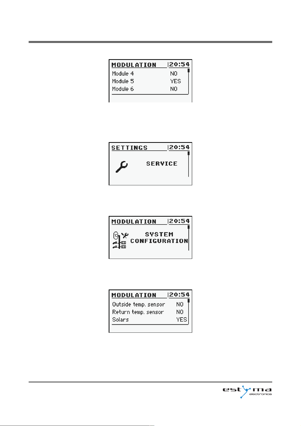
Find Module 5 and activate it by changing the settings to YES
Now enable the solar handling.
As the main menu select SETTINGS and then enter the access code in the SERVICE mode
After entering the code run SYSTEM CONFIGURATION
Find the position Solars and activate them by changing the settings to YES
After finishing configuration the controller we can start to change the adjustment and settings
for Solars. Description of the configuration these elements can be found in chapter 6.8.
page 54
PL20110629
Page 55
8 Specification
8 Specification
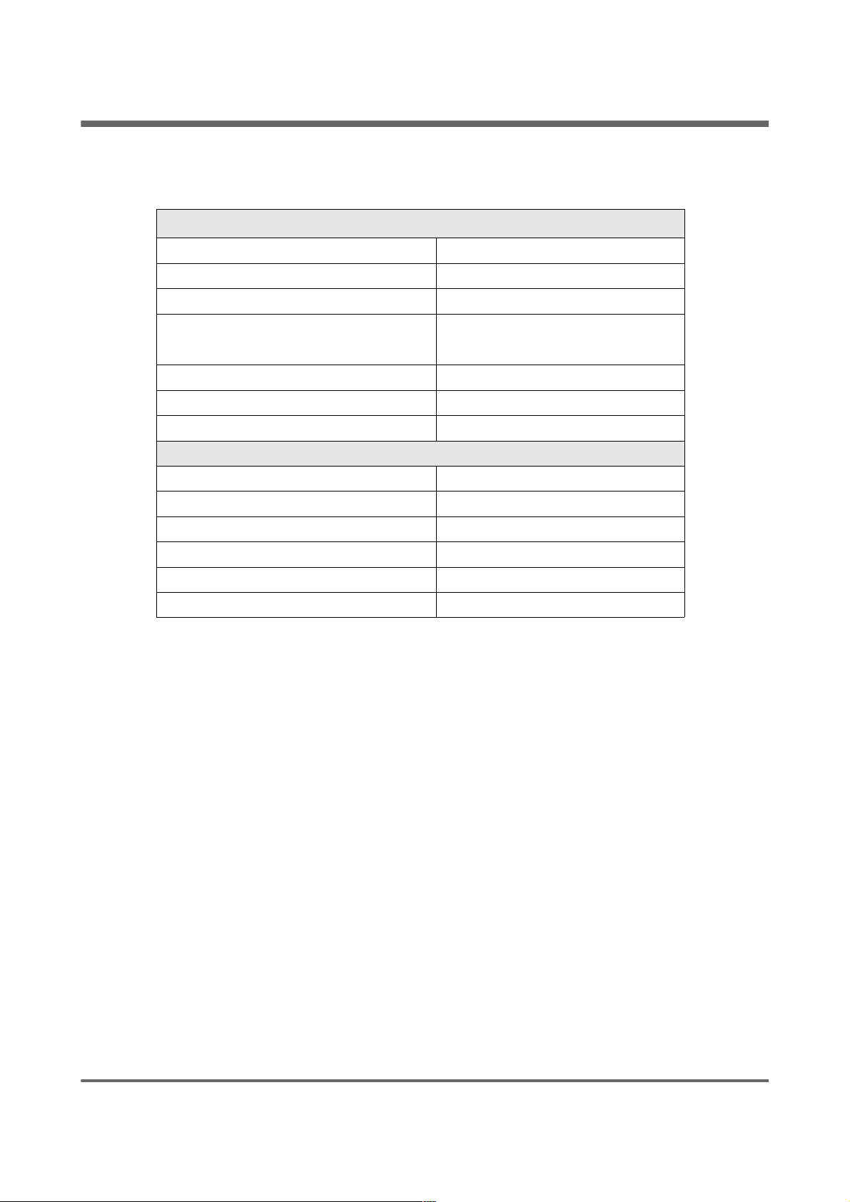
Technical data
Module supply voltage ~230V/50Hz ±10%
Power input (module) <6VA
Temperature measurement accuracy ±4ºC
Sensors NTC 10kΩ B
25/85
=3877K±0,75%
VISHAY BC components
Ambient temperature 0-60ºC
Moisture 5-95% non-condensing
Software class A
Module output load capacity
CH pump 100W
HW pump 100W
Igniter 400W
Blower 150W
Burner feeder 150W
Feeder tank 150W
estyma electronics
www.estyma.pl
page 55
PL20110629
Page 56

Manufactured by:
Estyma electronics
al. Lipowa 4
11-500 Giżycko
POLAND
tel. +48 87 429 86 75
fax +48 87 429 86 75
www.estyma.pl
page 56
PL20110629
 Loading...